1
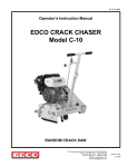
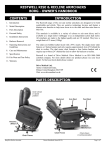
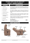
Nimbo Lightweight Posterior
Posture Walker
Assembly & Operating Instructions
with optional Forearm Platforms
with optional Pelvic Stabiliser
Please read these instructions carefully before assembling or operating this product.
Ensure you are familiar with all of the safety and operating instructions.
Contents
Technical Specification
1
Optional Accessories
3
Important Safety Information
2
Assembly
4
Care and Maintenance
2
Fitting the Optional Accessories
8
Parts
3
Warranty
Back
Introduction
The Nimbo Walking Aid is available in five different sizes. It is used as a posterior walker
and is available with a number of accessories.
The Nimbo may be used outdoors but is restricted to smooth and even terrain without
obstacles. Examples of such terrain may include paths, pavements and playgrounds.
The Nimbo should not be used on rough or uneven ground, muddy conditions or on
grass or gravel. If the user wishes to operate the Nimbo in this environment, Outdoor
Wheels are available from Drive Medical Stockists under product code KA8100.
The outdoor wheels will not work on the lowest setting of the KA4200 or KA5200.
For this position and for use on the KA1200 we recommend the KA8100S.
Specifications
Code
Handle bar
Height
Overall
Width
Width inside
Handle Grip
Depth opened
at base
Weight
Weight
Capacity
KA1200N
37-47cm
53cm
34cm
64cm
4kg
45kg
KA2200N
48-64cm
56cm
34cm
74cm
5kg
45kg
KA3200N
50-77cm
64cm
38cm
84cm
5kg
90kg
KA4200N
72-91cm
64cm
41cm
91cm
6kg
90kg
KA5200N
92 104cm
74cm
48cm
94cm
7kg
125kg
All dimensions are metric.
Drive Medical is an ISO 9001 certified company.
For more details about our products please see your local dealer.
1
Important Safety Information
Please read all of these instructions fully before assembly or operation.
• Unpack and check that you have all of the parts and attachments shown.
• To avoid risk of suffocation to children or animals, dispose of the plastic bags correctly.
• Remove all packing materials and dispose of correctly.
• Pay attention to the environment and avoid obstacles, bad flooring or carpet and other
hazards.
• Ensure that only Drive parts are used on the Nimbo. Periodically visually inspect the
walker for signs of wear.
• Please ensure that only one person uses the walker at any one time, and do not
exceed the weight limit.
• Children using the Nimbo walkers should be supervised at an adequate level
dependent upon their individual ability.
• Always consult your healthcare professionals for advice on how to use the
Nimbo safely.
• Do not use the castor and / or reverse locks without professional instruction.
Care and Maintenance
Cleaning:
• Check the smooth function of the wheel sets regularly and prevent the wheel from
getting dirty. Clean regularly by hand with a damp cloth.
• Do not use any abrasive detergents. Solvents can damage the coating and surface of
plastic parts.
• Metal and screw connections must be checked regularly and to make sure that they
are stable. If necessary retighten the screws.
• The locking buttons must be checked thoroughly. Contact your dealer immediately if
the buttons are not functioning correctly.
• The bearing and tread of each wheel will wear differently depending upon the
environment, users weight, walking style and type of use. Regularly check for wear
and replace if required. The wheel should be lubricated regularly.
• After use in heavily muddy areas, etc the wheels and associated parts should be
washed down to remove excess dirt.
2
Parts Nimbo Walker
Front Swivel Wheels (pair)
Nimbo Frame
Rear Anti-reverse Wheels (pair)
Optional Accessories
Forearm Platform
Outdoor Wheels
Pelvic Stabiliser
Handgrips (pair)
Armrests (pair)
Armrest Supports (x 2)
Outdoor Wheels (x 2)
Pelvic Stabiliser
Washers (x 2)
Fixing Bolts (x 2)
Tools Required: 10mm and
13mm spanner, 6mm Allen key.
Seat
(See separate installation sheet)
3
Assembly
a:
1
2
1
b:
2
c:
4
3
d:
‘Click’
Step 1
The Nimbo has a foldable aluminium tubular frame which is height adjustable with each
leg numbered 1-4.
To open up the Nimbo: lay the frame on the ground with the front legs (1 & 2) on top (a).
While holding the back legs (3 & 4) pull up on the front legs 1 & 2 (b). When both legs are
fully extended (c) you should hear a ‘click’ as both buttons pop into position see detail (d).
Warning: Make sure that both buttons are in position before proceeding.
4
Assembly
1
1
2
‘Click’
Step 2
Each wheel is marked with a number 1 - 4, to match the numbers on the frame.
To fit the wheels: fit the first wheel (1) by pushing into the frame at position 1.
Push in until the button pops out of one of the holes. Repeat for the other front wheel 2.
Tip: You might need to rotate the tube slightly until the button pops out.
4
‘Click’
4
3
Step 3
Repeat the same procedure with the two back wheels 3 & 4, matching the numbers on
the frame. Push in until the button pops out of one of the holes.
Tip: You might need to rotate the tube slightly until the button pops out.
5
Assembly
Step 4
Lift up the frame and position onto its wheels. The front and the back wheels have 9
height positions.
To adjust the height: press in the button (arrow) and move the wheel to the required
hole position. Make sure that the button pops into position in the frame, you should hear
a ‘click’. Repeat for the other 3 wheels making sure they go into the same height holes
and the button pops into position.
a:
Step 5
b:
c:
OPTIONAL
The front wheels can be locked in a forward position.
To lock the front wheels: adjust them to point forwards (a), pull up the Locking pin and
turn 90° in either direction (b), release the pin to lock the wheels (c). To unlock the wheels
repeat the operation.
6
Assembly
Retaining clip
Pin
Step 6
OPTIONAL
The back wheels can be locked to stop the chair from rolling backwards.
To lock the back wheels: release the metal pins from the plastic retaining clips. Let the
pins fall into position onto the teeth on the wheels. To unlock the wheels, move the pins
back into the plastic clips.
Warning: The brakes will only stop the chair from rolling backwards, the chair is
still able to move forwards.
Step 7
To fold the walker: push in the two button in the cross tube (arrowed) and push down
on the front wheels. You might need to turn the wheels slightly to close the walker fully.
7
Fitting the Forearm Platform
Hand
rail
Step 1
Removing the hand grips: the hand grips are factory fitted and are a tight fit they will
need to be cut off using a sharp knife before the forearm platform can be fitted.
Carefully using a sharp knife make a cut along the hand grip, peel back the grip and
remove from the hand rail. The hand grips cannot be reused and should be discarded.
a:
b:
Hand rail
c:
Upright
Step 2
To fit the armrest supports: remove the nut, washer, spacer, bolt and middle spacer
from the hand rail (a). Slide on the armrest support, there are four holes for adjustment (b).
Line up one of the holes in the armrest support, push the bolt through the armrest
support, slide the middle spacer and the upright onto the bolt and secure with the
spacer, washer and nut (c). Repeat for the other side making sure that you use the same
hole in the armrest support.
8
Fitting the Forearm Platform -
continued
Spacer
Knob
Lever
Step 3
Step 4
Bolt on the armrest. The armrest comes
with 2 spacers for lateral adjustment,
these should fit between the armrest and
the armrest support as required. Secure
the arm to the armrest support using the
nuts, bolts and washers supplied.
Slide in the handgrips to the required
position and tighten using the knob on
the underside. The hand grips can also be
rotated by sliding out rotating and sliding
back in, tighten the knob. The hand grips
can be angled forwards as required by
releasing the lever, adjusting the hand grip
and retighten.
Fitting the Outdoor Wheels
Step 1
Outdoor wheels replace the existing front castor wheels. They are a larger diameter
(9”) and are locked in a forward facing position so are better at negotiating rougher
terrain and small obstacles.
Remove the existing front wheels and replace with the outdoor wheels following step
2 on page 5, ensure the buttons lock into position. Ensure that the outdoor wheels
are set at an equal and comfortable height. Adjust the height of the rear wheels if
required. The height should be set so that the hand grips are near horizontal.
9
Fitting the Pelvic Stabiliser
Hand grip tube
Step 1
Washers
& fixing
bolts
Step 2
Position the pelvic stabiliser up under the
back of the hand grip tube as shown.
Line up the holes and attach from behind
using the washers and fixing bolts, only
hand tighten the fixing bolts.
a:
b:
Adjuster
knobs
Step 3
Adjuster buckles
Catch
Clip
Step 4
To adjust the pelvic stabiliser:
Loosen the two adjuster knobs shown
and position the side pads as required.
a: To release the buckle: Press in at the
two points shown and pull the clip and
catch apart.
Re-tighten the adjuster knobs.
b: To secure the harness: Insert clip into
catch.
To adjust the harness: Slide the strap
through the adjuster buckles to adjust the
length as required.
10
Warranty
Your Drive Nimbo comes with a comprehensive 24 month warranty. For warranty issues
and claims please contact your Drive Medical dealer. The warranty conditions are below:
1. Any work or replacement part installation must be carried out by an authorised Drive
Medical dealer / service agent.
2. To apply the warranty should your Drive Nimbo require attention please contact the
your Drive Medical dealer / service agent.
3. Should any part of the Drive Nimbo require repair or full or part replacement as a result
of a manufacturing or material defect within 24 months of receiving the Nimbo, parts
will be supplied free of charge. Note: The guarantee is not transferable
4. Any repaired or replaced parts will be covered by this warranty for the balance of the
warranty period on the armchair.
5. Parts replaced after the original warranty has expired will be covered by a three month
warranty.
6. Consumable items supplied will not generally be covered during the normal warranty
period unless such items require repair or replacement clearly as a direct result of a
manufacturing or material defect.
7. The above warranty conditions apply to brand new chairs. If you are unsure whether
your chair is covered, check with the service agent / dealer.
8. Under normal circumstances, no responsibility will be accepted where the Nimbo has
required assistance as a direct result of:
a. The Nimbo part not having been maintained in accordance with the manufacturer’s
recommendations.
b. Failure to use the manufacturer’s specified parts
c. The Nimbo or part having been damaged due to neglect, accident or improper use
d. The Nimbo or part having been altered from the manufacturer’s specifications or
repairs having been attempted before the service agent / dealer is notified.
e. Any unauthorized modifications carried out without approval of the manufacturer will
make the liability null and void. This includes the overstepping of the maximum loads.
In the event of your Nimbo requiring attention, please contact your service agent / dealer
and give all relevant details so they can act quickly. Please contact Drive Medical for
advice if you do not know where the Nimbo was originally purchased from.
The manufacturer reserves the right to alter without notice any weights, measurements
or other technical data shown in this manual. All figures, measurements shown in this
manual are approximate and do not constitute specifications.
Drive Medical Ltd
Ainley’s Industrial Estate, Elland, West Yorkshire HX5 9JP
Web: www.drivemedical.co.uk