1
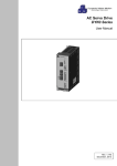
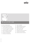
ES5200 User Manual
Contents
1.ES5200 Access Controller brief introduction .................................... 3
1.1 Summarize ........................................................................................ 3
1.2 Structure diagram .............................................................................. 3
1.3 ES5200 Parameters .......................................................................... 3
1.4 ES5200 Functions ............................................................................. 4
1.5 ES5200 Packing list .......................................................................... 6
2. ES5200 Keypad operation ............................................................................... 6
2.1 Error prompt........................................................................................................... 6
2.2 keypad instructions ................................................................................................ 7
2.3 system settings ...................................................................................................... 7
2.3.1 Edit password of the controller
控制器设置密码修改................................... 7
2.3.2 Date and Time settings .............................................................................. 8
2.3.3 network communication ............................................................................. 9
2.3.4 Controller Parameters ............................................................................. 10
2.3.5 infared monitor ........................................................................................ 10
2.3.6 control byte ............................................................................................. 11
2.4 add/delete card by keypad ................................................................................. 13
2.5 open infare by the keypad.................................................................................. 14
2.6 open door and edit password by the keypad ......................................................... 14
2.7 secondary encrypt ........................................................................................... 15
2.8 reset controller password ................................................................................... 15
3. ES5200 connection defines ........................................................................................... 16
3.1 RJ45 change-over panel functions instructions ................................................. 16
3.2 ES5200 RS485 communication ........................................................................ 17
3.3 ES5200 extend electrical control lockl .............................................................. 18
3.3.1 ES5200 extend single lock ...................................................................... 18
3.3.2 ES5200 extend double lock................................................................... 19
3.4
ES5200 extend card reader ............................................................................ 20
3.5
ES5200 extend infare ..................................................................................... 21
3.6
ES5200 extend exit button and emergency input ............................................ 21
4. installation instructions ..................................................................................................... 22
4.1 preparation before installation .............................................................................. 22
4.2 installation of the controller ................................................................................ 22
5. common problems and questions .................................................................................. 23
5.1 why using RS485 to be network, but can not communicate?................................. 23
5.2 how to extend the communication distance for RS485/422? ................................. 24
5.3 why display ERR 00 when swipe card? ................................................................ 24
5.4 card is registered the authorization by the software, why still display ERR 08 when
swipe card? ............................................................................................................... 24
5.5 what is “confirm time delay” of the invasion detection (infared) sensor? ................ 24
5.6 how to close Door Status alarm? .......................................................................... 24
5.7 how to close Infare alarem? ................................................................................. 25
5.8 Closed the infared alarm after swipe legal card, why after the delay time alarm
again? ....................................................................................................................... 25
5.9 Why press the Exit Button but no response? ........................................................ 26
1
ES5200 User Manual
5.10 Why display HALT swiping the card? .................................................................. 26
5.11 Why mistake door open happened?.................................................................... 26
5.12 Why the controller make voice “Beep” frequently? .............................................. 27
5.13 Why display ERR 02 and can not delete? ........................................................... 27
2
ES5200 User Manual
1. ES5200 Access Controller brief introduction
1.1 Summarize
ES5200 include ES5200 host controller, RJ45 connection change-over panel, DC12V/3A
power supply. Good installation, wireless connection and wiring look. With the special security
of proximity intelligent card, electric lock, infrared sensor and network communication, it
makes safety and intelligent In-Out controlling system, which also have network connected
security and monitor functions. It is widely used in Bank Access Control and Smart residential
area etc.
1.2 Structure Diagram
ES5200 is installed inside a metal box, all the extend wireless are connected with the RJ45 change-over
panel, and change to network wireless through the bottom to connect with the outside. As Figure 1.1, having
power supply, and the function settings are set already, for the device parameter settings it will be better to
make settings by the software, easy to operate and manage.
Figure 1.1 Structure Diagram
parameters
1.3 ES5200 Function
Parameters:
Size
L382mm×W200mm×H71mm
Color
Black
Display
6 characters digital LED display:
Color: red
Illuminance: >150 Lux
Keypad
17pcs conductive rubber pad:
Color: grey;
Pressure:100g-1000g; MAX=10Kg;
Times: more than 100 thousand times.
3
ES5200 User Manual
Net
Weight
2550g±3%
Power
DC:
Voltage: DC12V±5%
Current: do not read card 30-50mA
Read card drive the relay and buzzer <100mA
Ripple wave: >500mV / 1KHz
Instant absorption interference: >2000V/600W/100µS
more or less because of the different packing
Relay output:
:
MAX DC12V/2A/25Sec
Drive
Temperat
ure
Humidity
Time
DC24V/2A/25Sec
AC75V/3A/25Sec
Not use:
℃ ~ +55℃
-20℃~ +70℃
Working:
Not use:
20%--90%
5%--95%
Working:
0
Deviation: <±30 seconds per month
:
,
,
EFT ±2kV 5kHz power supply and all the input and output ports;
EMI
Noise of flexibility: ±2kV, power supply and all the input and output ports;
ESD Immunity: ±6kV contact discharge, ±8kV air discharge, all the leakage
technical parts and terminals
Commun
ication
Interface
RS485
User
Record
Registered user: 1700 ( can be extended more than 10 thousand )
Records: 6144 ( can be extended more than 10 thousand )
1.4 ES5200 Functions
1.4.1 Maximum registered different users: 1700
Card No. of the proximity card ( 5 bytes );
User ID ( 4 bytes );
Valid date of user ( Jan 1, 2000 to Dec 31, 2099 );
Personal password of the user ( 4 bytes )
Types of user ( normal user, special user VIP );
Limit of the allowed time interval;
1.4.2 Support many kinds of way to open:
Swipe the card to open the door ( single car, double cards );
Swipe card and user password ( keypad );
User ID and user password ( keypad )
Remote control;
Exit button;
1.4.3 Support network:
Working settings of the controller edit or change;
User management: authorize (add user), or cancel authorization (delete user);
4
ES5200 User Manual
Data collecting: story records loading;
Reald time monitoring: door open or close, infrared monitor, status of the
controller etc.;
Remote control;
Communication standard under the standard of YDN023-1996;
1.4.4 Time interval control:
)working days and holidays management entry time interval
1
Working days: can set 16 limited time interval list, for different user, every list can
have 6 different limited time interval;
Resting days and Holidays:
Resting days in a week: for every week, can be set none, any day or any two days
as resting days;
Legal holidays: can be set 40 groups;
For example, Jan 1, May 1 etc.
Can set one allowed time interval list, have 4 different allowed time interval.
)
2 Managing allowed time interval by week( from Monday to Sunday )
Can set 16 allowed time interval list, for different user, every list have 6 allowed time
interval.
)
3 Protection period: normally open, normally close, intrusion detection, switch monitor,
second times password confirmation.
1.4.5 Keypad operation ( standalone only ):
System control parameters settings, time clock timing;
Add user;
Delet user;
Open infrared monitor;
User ID and password to open;
1.4.6 Environment monitor, and event management:
Door open or close monitor ( install the door switch );
Monitor the detector such as IR/ID monitor, or connect with smoke sensor;
Swipe card legal or illegal records;
Controller parameters are changed;
Allowed-in user settings are changed;
Support “linkage”operation functions;
1.4.7 Support many various electrical magnetic locks
Normally open, normally close;
Relay drive time: 0.1 seconds to 25 seconds finish settings;
Open relay of waiting for in: 2 seconds to 25 seconds finish setting;
1.4.8 Record details:
All the events will real time making record, maximum records are 6144 records;
1
)Door open records:
)
Records of swiping card to open the door;
Records of using User ID and password to open the door;
Records of manually push button to open the door;
Records of using RS485 remote control;
2 Monitoring records
Records of chaging working parameters of the controller;
Records of open and close the infare monitor;
Records of registered user swipe card but do not go in, or go in but do not close
the door on time;
Invalid swiping card ( unregistered card try to swipe card and go in);
5
ES5200 User Manual
Invalid authorization ( out of valid date, or unauthorization of the limited time
interval) try to go in;
3
)Alarm records:
Infared sensor alarm ( illegal entry );
Door is open unnormally ( illegal entry );
1.4.9 Alarm Output:
ES5200 support OC door alarm output, and can set the output status in alarms.
1.4.10 6 characters LED digital display:
Real time display;
Keypad operation remind;
Swiping card operation remind;
Alarm codes remind;
1.5 ES5200 Packing List
White box: barcode tag outside;
ES5200 1pcs ( Model tag and Date of manufactured );
Fixed gel column, tapping screw abatch;
AC220V power plug wire 1pcs
User Manual ( include Wireless connection and installation map )
Guaranty card and Certification
2. ES5200 Keypad operation introductions
ES5200 have various keypad operation: system time setting, controller working
parameters setting, register card or delete by keypad, password open and “Infare
anti-intrustion” protection etc.
2.1 ERROR prompt
ERR 00: Card No. inspection error. If the controller receive the Card No. that is read
by the reader does not follow the ruled data format, controller will show
ERR 00. Reason for this error is the data maybe interfered at the data
transportation or wrong connection of WD0 and WD1;
ERR 01 after swiping card, but do not close the door. ( after open the Open-Close
status monitor functions of the door )
ERR 02 Right swiping card, controller open the door relay, but no merchanical
operation ( pulse electic magnetic lock )
ERR 03 Infared alarm ( after open the infared monitoring function of the controller),
please transfer Chapter 7.
ERR 08 unregistered card swipe;
:
:
:
:
6
ES5200 User Manual
:
:
:
ERR 09 ”out of date “ of the registered card, can not entry the previous authorized
allowed area.
ERR 10 regisgered user try to entry the protected area at thenot-allowed entry time
interval when the controller is under the allowed time interval monitoring.
ERR 11 “swipe card and password entry management”, right swiping card, user
input wrong password three times, no authorization to entry, when remind
“HALT”, must wait around 2 minutes to retry again.
2.2 Keypad instructions
Number keypad: 0, 1, 2, 3, 4, 5, 6, 7, 8, 9 for inputing the numbers;
Function keypad: F1, F2, F3, F4, F5, ESC, ENT for functions operation.
F1 entry functions setting, change password;
F2 parameter setting of the entry controller;
F3 entry user management;
F4 invasion sensor protection by keypad;
F5 input user ID and password to open the door;
ESC exit setting;
ENT confirm input or setting;
2.3 System settings
Enter the system and make settings, must have “keypad setting”
confirmation of the password: press F1, LED display “PIN---“, input 6
numbers as keypad setting password. If correct input, LED display “CAN SET”.
If wrong input, LED display “PIN ERR”, can input again, but only three times, if
all the three times are woring, LED remind “HALT”, must wait for a few while
and then can input again by the keypad. Afer the password confirmation,
controller can load the keypad settings. If the interval more than 8 seconds
and no operation, the controller will automatically close the allowed setting
authorization. Next time to make settings, must confirm the password again.
:
:
:
:
:
:
:
2.3.1 Controller settings password edit
Press F1 to edit the settings password:
After LED display “CHG PIN”, and need to input the new password, it will
remind “————”, input the six numbers of password, and ENT to confirm,
LED will remind second times confirmation “AGAIN”, it will display “————”,
input the six numbers again, the numbers must be the same to be valid,
ES5200 make the new password as the keypad password.
Attention
!!!
“keypad settings passord” is the part of the systempassword of
the controller ( 5 bytes )= software aggravating password ( 2 bytes)
7
ES5200 User Manual
+ keypad settings password (3 bytes). So using keypad to change
“ keypad settings password”, must change the device “system
password” which is saved inside the software database in the
computer.
2.3.2 Date and Time settings
After the password confirmation, controller load the keypad settings, press F2 to
display or edit the control parameters.
LED display as the following
YY number low-order of the year, such as 2000, high-order fixed 20,
low-order 00-99 can be set press ENT to edit, LED display “—”,
input the new number, press ENT again to confirm. Such as input
“3”, press ENT means the low-order is 3, it is 2003.
(
NON
:
)
number display the present “month” of the controller, such as “NON
11” means November, press ENT to edit, LED display “—”, input
the new number, press ENT again to confirm. Such as input “3”,
press ENT means the month should be 3, it is March.
DD
number display present “date” of the controller, such as “DD 18”
means 18th, press ENT to edit, LED display “-“, input the new
number, press ENT to confirm again. Such as input “16”, press
ENT, the “day” is 16, it will be 16th.
DE
number display the present “week” of the controller, such as “DE 5”
means Frida. Controller will calculate the day to display as
reference.
HH
number display the oresent ‘Time”, such as “HH 18” means 18:00,
press ENT to edit, LED display “-”, input the new number, press ENT
again. Such as input 16, press ENT means 16:00.
NIN number display the oresent ‘Time”, such as “HH 18” means 18
minutes, press ENT to edit, LED display “-”, input the new number,
press ENT again. Such as input 16, press ENT means 16 minutes.
SS
number display the oresent ‘Time”, such as “HH 18” means 18
seconds, press ENT to edit, LED display “-”, input the new number,
press ENT again. Such as input 16, press ENT means 16 seconds.
8
ES5200 User Manual
2.3.3 Network communication
ID
number display the address code #1 of the controller, limits 1—254
press ENT to edit, inpute the number and press ENT to confirm.
Such as press ENT, LED display “__”, input 114 and press ENT, it
makes RS485NET address code # 1 changed to 114. For example,
inlput wrong, re-input is requested.
grP number display the packet address ( GROUP) of the controller, range
0—15. If the connected devices are more than 254 pcs in one
RS485 system, it will make the devices as 0-15 groups (total 16
groups). So the RS485NET address ID of the controller. It is called
address code in the group. Press ENT to change, input the number
and press ENT to confirm. For example, press ENT, LED display “-“,
input new number 1 and press ENT, make the RS485NET as group,
address code change to 1. If wrong input, re-input again means
make the device as GROUP=1, CID1=114, means addess code in
group is 114.
BAUD number speed between the controller and the system, =0 means
4800BPS; =1 means9600BPS; =2 means 19200BPS; =3 means
2400BPS. Using RS485 as the communicate between controller and
the system., maximum distance is 1000m, in one net line can
connect 32 controllers at the most, but do not advice to do that,
because once the net line was cut by the accident, or the drive of the
controller have some problem, it will make troubles of all the devices
normal user, and it is also not easy to make the maintaince. Here
propose to use concentrator to do the project. It make one net line as
4 separate branch lines, the branch line can connect 32 devices at
the most. Even one branch have problems, the other branch lines
also can work well.
ES5200 use RS485 for the communication, can support the
verifications are as follows:
SPACE verification; MASK verification; ODD verification;
EVENverification; NO verification.
Default support: 1start bit, 8 data bit, 1 stop bit, no verification bit.
S.O.E number verification methods of RS485 network communication:=0 no
verification; =1ODD; =2 evenparity verification; =3 MARK 1
verification; =4 SPACE 0 verification.
default =0 1start bit; 8 data bit, 1 stop bit, no verification.
( ):
()
9
()
ES5200 User Manual
2.3.4 Controller parameters
rLY number means the operating time of the relay get the signal to open
the door, unit: 0.1 second; for example “RLY 30” means: =3
seconds. If the electic magnetic lock is power up door open (close),
power off will open (close) the door automatically, so “RLY delay” and
“OPT delay” are the same; if the electric magnetic lock is power up
door open (close), power off can not automatically open (close) the
door, so “RLY delay” and “OPT delay” are different. Maybe “RLY
delay”=0.2 seconds, but “OPT delay”=2 seconds.
(
)
OPT number means OPEN DELAY unit: 0.1 seconds , for example
“OPT 20” means “open delay”=20 X 0.1=2 seconds. Press ENT to
change, input new number (20—255 and then press ENT to confirm.
For example: press ENT, LED display“—”, input 100 and press ENT,t
the “open delay” is changed to 10 seconds. If wrong input (greater
than 255 or less than 20), request input again.
“Open delay” define:
Legal swiping card, controller is waiting for open the door, do not
open the door to entry at this time, it will make a record “swipe
card but not entry alarm record”, ouput the alarm or not, it depends
on the electic magnetic lock can close the lock when controller
close it or not. If it can be lock, no alarm; if not, the door is actually
open, need open and close these merchanical operation, using
merchanical pressuer can press the spring inside the lock back to
lock. It is for electric impulse lock.
So, “Open delay” means after swiping card, in this time interval to
inspect the door open or close, open delay finished inspect if the door
is closed, dual use.
)
2.3.5 Infared monitor
IrS. number From appear the infared alarm to be confirmed by the controller it
is the relay time of the alarm; infared alarm happens, not always
alarms, if there is legal swiping card in the delay time, it is not
alarm. And after the legal card is swiped, controller will close the
infared monitor. If in the delay time there is no legal card swiped,
the system will make it as illegal entry monitoring area to make
alarm. Unit: 0.1 seconds. For example “IrS. 50”
means:=5seconds, means the time from the legal user entry the
monitoring area, until swipe the card on the reader.
IrT. number allowed registered people using ES5200 keypad to open the
10
ES5200 User Manual
infared sensor monitoring, controller will have a delay time to let the
authorizated people to leave in case it illegal entry the monitoring
area to have alarm. Unit: 0.1 seconds, for example “IrT 50” means:
=5 seconds, meaning: legal people open the infared monitor through
the keypad, depaly 5 seconds to let him leave.
AL.d. number effective drive tim of the alarm OC output. At the alarm, when
OC output “break over” or “disconnect”, the settings are made D3 bit
in the sheet C2 second control byte ( check Chapter 2.3.7) AL.D valid
range 0-255; valid time 0.1—25.5 . AL.D=0 stop the alarm output.
秒
2.3.6 Control word
C1
number working method of the controller control the first byte
(default=0). The calculate way as follows: one byte (D7—D0
high bit , defines as follow:
)(D7
)
BIT
D7
D6
Defines
control
=0
Do not monitor the door open or close status
=1
Monitor the door open or close(through door switch), unusual alarm
(1) unusual open the door;
(2) lock which can not close door automatically, swipe card and then
close the door merchanical operation;
(3) after open delay finish, door still not close.
=0
Not use infared monitor
=1
Infared monitor, illegal entry the monitoring area and alarm, make
records. Legal swiping card to entry, or input user ID or password to
entry on the KEYPAD, RS485 remote control to open (entry), controller
will automatically close infared monitor. Using RS485 remote control to
open, or using KEYPAD to open directly.(using KEYPAD can not close,
open only; legal swiping card only can close.
=0
Electric magnetic lock close automatically after power off (or power up)
=1
Must be “open and then close” using elastic force of the
merchanical operation to be closed.
=0
Can use “open manually” short circuit signal wireless and GND wireless
to open the door; =1 forbidden.
=0
Set the door switch output level as:
Door open the two signal wireless is short circuit (connect); door close,
two wireless are open (block up).
=1
Set the door switch output level as:
Door open the two signal wireless is blocked up (open); door close, two
wireless is short circuit (connect).
)
D5
D4
D3
11
ES5200 User Manual
=0
Set the output level of the infared detector: short circuit (connect) as
alarm;as usual (no alarm), two signal wireless is short circuit (block up)
=1
Set the output level of the infared detector: alarms, signal wireless short
circuit (block up); normally (no alarm), signal short circuit (disconnect)
=0
Legal swipe card, can open the door, no more confirm password
again.
=1
Swipe card, must confirm password and then open the door.
=0
Do not allow using keypad press ENT only to open the door
manually.
=1
Allow using keypad to press ENT to open the door manually, no more
EXIT BUTTON.
D2
D1
D0
( )
( )
( )
( )
For example: open door switch monitor:
D7=1 =128
Do not use infared monitor
D6=0
Lock can not be locked automatically
D5=1 = 32
Allow to use open door manually
D4=0
Door switch open circuit when door open
D3=1 = 8
Password second confirmation
D1=1 = 2
not allowed to press ENT to open door
D0=0
Plus all 128+32+8+2 = 170 input 170 by the keypad and present
to confirm
)
C2
(
number working method of the controller control the second byte
(default=0). Calculate it as follows: one byte D7—D0 D7 high
bit , define as follows:
(
)
BIT
D7
D6
control
=0
=1
=0
=1
D5
)(
defines
Linkage input CPIN1effective electrical level
Linkage input CPIN2 effective electrical level
“linkage CPLD1,CPLD2” input, controller will give
response the ruled operations
D4
D3
=0/1
D2
=1
Swipe card and send the Wiegand signal to the computer
which is connected by RS485. =0 forbidden
=1
“emergency event” input MDIN and GND close, close
the door. Any card no response
=0
“emergency event” input MDIN and GND closed,
always open
=0
Personal input ID and password to open the door
forbidden
D1
D0
ALARM output connect =0 when it alarms; open circuit=1
12
ES5200 User Manual
=1
Allow input ID and Password to open the door personally
Remind: linkage input CPIN3, the effective electric level is fixed by the
controller as: low electrical level (-0.5V---0.3V or touch point input
means short circuit.
)
C3 number working method of the controller control second byte (default=0).
Caculate it as follows:
One byte D7—D0 D7 high bit , defines as follows:
(
BIT
D7
D6
)(
)
defines
Control
=0/1
=0
=1
=1 using usual closed time interval, in the set closed time,
usually close the door.
=1 using usual open time interval, in the set open time, open
the door (except holidays and rest days)
D5
=0/1
=0 inspect the allowed time interval of the allowed
people, =1 do not inspect
D4
=0/1
=0 inspect the valid authorized date of the allowed
people, =1 do not inspect.
D3
=0/1
=1 open intimidation alarm function; =0 close
=0/1
=1 time interval for right swiping card and personal password
open
=1
Fission swipe card head right swiping card and must
input personal password
=0
Fission swipe card head right swiping card
=1
Subject swipe card head after right swiping card must
input personal password
=0
Subject swipe card head swipe card right will be ok
D2
D1
D0
2.4 Add card or delete card on the keypad
After the password confirmation, press F3, start add or delete card operation, LED will
display as follows:
ADD CD add card
Press ENT to start, display “ID --” requests to input the User ID No. which will
hold the card ( for the details check Appendix 2), in the system, every user have one
User ID and one card, if lost the card can cancel its authorization, and issue a new
one, the User ID no need to change. User Id is comprised by four number, such as
input 0145 and press ENT, means ID No. of the new user is 0145; If the ID No. is
exist in the controller already, LED will display HAS IT, and request to input again.
LED display “UD----” means to input the authorization valid date of the user,
from the beginning issue the card to the end of the card authorization. For example,
13
ES5200 User Manual
expired date is May 23, 2004, input 040523 and press ENT. If press ENT directly
means the expired date is Dec 31, 2099, it is always valid.
After input the valid date, LED will display CARD, means Please swipe card,
the controller will automatically set this card as Allowed Entry Card. If the Card No. is
exist in the controller already, LED will display HAS IT, it is not allowed that one card
for different user by the controller. If want to change a new card, swipe the card
again.
Controller will automatically give the new user a default password (PIN): 1, 2,
3, 4. the user can set its PIN itself (check the details as follow). Controller add 1 for
the user id automatically to the new card. If the new user id is not exist in the
controller, display “-CARD-”, then swipe the next card again, and its corresponded
user id as: 0145+1=0146, repeat the same operation. Press ESC to quit. If the user
id that the controller made is exist in the controller already, controller requests to
input the user id again to start.
Attention: Doing the keypad operation on the controller can not issue the personal
password of the user or change the password to be 0, make the settings on the
computer throught the software only.
DEL CD Delet card
After press ENT, LED display “-CARD-”, swipe the cads that plan to delete one by
one, if the card which is planning to delete is not exist in the controller, it will display
“NO CD” means no card need to delete, and the corresponded user is also
canceled, means cancel the authorization.
DEL ID Delete user
After press ENT, LED display “ID -” inquires to input the user ID that want to delete.
For example, 0145 press ENT, means delete the user which ID is 0145, and its
corresponed card authorization is also canceled.
DEL ALL Delete all
Press ENT at the first time, LED display “AGAIN”, ask for second ENT to confirm,
and then make all the entry and exit records be cleaned. If do not press ENT to
confirm, can not do the Delete operation.
2.5 Open the infare on the keypad
?
Press F4. LED display “Ir ON
”, press ENT to confirm, means open the
infared monitor. The controller will close the area infared monitor after the legal
swiping card to entry the limited area. If all the people leave, need to open the
monitor by the keypad again. Press ENT to confirm to start the monitor, controller will
make a delay (for details please check Chapter 2.3.6) to wait for the people leave
the limited area. Using keypad can open the monitor only, can not close, only the
legal swiping card can close the monitor.
2.6 Password open the door and personal password edit by the keypad
Press F5, LED display “ID -”, inquires to input User ID. If the controller does
not have this user, LED display “NO USER”. Input the User ID (four numbers)
correctly and press ENT, then inquires to input “PIN -”; For example, 1, 2, 3, 4, and
press ENT. If the PIN is correct, controller open the door, if not, LED display PIN
14
ES5200 User Manual
ERR.
LED display “PASS”, press F5, LED display “CHG PIN” and press ENT to
confirm, LED display “PIN -”, inquires to input the new personal password (four
numbers, can not be 0000, ENT to confirm), then LED display “AGAIN” inquires to
repeat, input the new password again, the password should be the same, and then
the controller will save the new password and delete the old password.
Four number are all 0 of the password here make it special, it must using
the software to make the setting. People who hold the 0000 as the password,
when they use swipe card and password methong do open the door, no need
to input the password. This is just for some special people to be their
password.
2.7 second encrypt
After swiping card correctly, LED display “PIN -”, input the password on the
card reader and then open the door, controller will wait the user for 5 seconds to
input the password, and then ENT to confirm. If input the wrong number, LED display
“PIN ERR”, inquires to input again, if wrong input three times, controller will not allow
to input again. If the user forget its password, must use the system management
software to get the user information, the user password is one of the contents of the
user information. Or delete this user from the controller, and issue again, after issued,
“1,2,3,4” is as the default password, user can change it themselves.
2.8 Reset the controller password
If forget the controller password (not different with the personal password) can
not go inside the system to set. Software database broke up, lost the device
password, can not make the communicate between the device and the software.
Doing the settings as follows:
(1) Power off the controller;
(2) Opent he controller, short circuit the inside password reset jump take
“RST”;
(3) Power on, wait for the controller to display the time;
(4) Power off, push aside RST short sub jump take, and install the controller
again;
(5) Power on again, all the numbers of the system password (5 bytes) will be
0.
Means: software aggravating password (2 bytes) will be 0,0;
Keypad set password (3 bytes) will all be 0;
15
ES5200 User Manual
3. ES5200 connection defines
3.1 RJ45 change-over panel functions instructions
ES5200 make the connection easier through RJ45 change-over panel, as Picture 3.1
Picture 3.1
RJ45 Change-over connection defines
1. RJ45-RS485 defines
No.
Sign
1
2. RJ45-LOCK defines
Wireless
Orange white
2
orange
3
Green white
No.
6
7
3
8
4
GND
blue
1
5
GND
Blue white
2
green
3
6
7
485 A
Brown white
4
8
485 B
brown
5
16
Sign
1
.+
2.-
1.+
2.-
1.+
2.-
4
.NO
.C
Wireless
Orange white
orange
Green white
Blue
Blue white
Green
Door
switch--Brown
white
GND-brown
ES5200 User Manual
3. RJ45-READER defines
4. RJ45-IR/ID defeinse (infared interface)
No.
Sign
Wireless
1
WD0
2
WD1
Orange
white
Orange
3
No.
Sign
Wireless
1
+12V
Orange
white
Orange
2
Green white
Blue white
4
GND
Green
white
Blue
6
Green
5
GND
Blue white
7
Brown white
6
Green
8
Brown
7
Brown
white
Brown
4
GND
5
+12V
3
Blue
8
5. terminal blocks defines
IR/ID
No.
Sign
Wireless
No.
Sign
Wireless
1
HDIN
Exit button anode -- yellow
8
1
2
GND
Exit buttone cathode--black
9
N.C
Electric
control
lock
anode--red
Alarm output (obligate)
3
MDIN
Fire linkage anode--orange
10
COM
4
GND
Fire linkage cathode--black
11
N.O
5
4
Lock public terminal--white
12
GND
Lock door switch usual open
terminal--white
Electric
control
lock
cathode--black
13
+12V
6
7
.C
3.NO
2.-
.+
Power
supply
input
cathode--black
Power
supplyinput
anode--red
3.2 ES5200 RS485 communication
ES5200 use RS485 communication interface,, inquires the devices hand in hand
chain connection methods. Such as Picture 3.2;
Picture 3.2 ES5200 RS485 communication connection
17
ES5200 User Manual
Remark: RS485 inquires the devices to be connected hand in hand chain connection
ways, the terminals must connect with 120Ω terminal resistance.
RJ45 change-over panel provide 120Ω terminal resistance as incoming end, as
Picture 3.1 JMP1.
JMP1 485 receiving end resistance defines
Needle jumping No.
Operation
Defines
1,2 short circuit
Terminal matched resistance not switching in
2,3 short circuit
Terminal matched resistance not switching in
JMP1
3.3 ES5200 extened electric control lock
3.3.1 ES5200 extened single lock
Picture 3.3.1 ES5200 extend single lock
Remark: 1. aboved two kinds of extending single lock, its internal port is the same,
select one is ok;
2. ES5200 extend single lock, JMP3 jumping take must be set as 2,3 short
circuit (Picture 3.3.1), JMP3 make defines as follows:
JM3 single lock/double lock settings defines
Needle jumping No.
Operation
Instructions
1,2 short circuit
Connect double locks
2,3 short circuit
Connect single lock
JMP3
As picture 3.3.1, when the lock that ES5200 extended is usual open (power off lock
open), if the lock is usual closed (power off close) actually. Please check the following sheet
JMP2 kinetic energy definition:
18
ES5200 User Manual
JMP2 usual open/usual close settings define:
Needle jumping No.
Operation
1,2 short circuit
JMP2
2,3 short circuit
Instructions
接常闭锁(断电锁
Connect usual close lock (
闭)
Connect usual open lock (power off lock
open)
3. Picture3.3.1 extend usual open lock, JMP2 must be 2, 3 broke up status. For
example extend usual closed lock, JMP2 must be 1, 2 borke up status.
3.3.2 ES5200 extend double lock
Picture 3.3.2
ES5200 extend double lock
Remark:
1. Above two methods of extend single lock are the same as the internal port,
optional;
2. ES5200 extend double lock, JMP3 jumping take must set it as 1, 2 short circuit
(Picture 3.3.2), JMP3 defines check Chapter 3.3.1;
3. Picture 3.3.2 extend usual open lock, JMP2 must be 2, 3 broke up status. If
extend usual closed lock, JMP2 must be 1, 2 broke up status;
4. Extend double lock, use RJ45-LOCK to extend double lock, because of the
defines of the RJ-45 change-over panel inside connection, door switch of the
lock must set it closed, door open; the principle is as picture 3.3.2.1
19
ES5200 User Manual
Picture 3.3.2.1
Connection principle of the double lock door switch
Both ends of the door switch “4.C” and “3.NO” are closed when the door is closed, when
the door is open, it will be broke up.
3.4
ES5200
extend card reader
Picture 3.4
ES5200 extend card reader
20
ES5200 User Manual
3.5
ES5200 extend infare
Picture 3.5
3.6
ES5200 extend infared input
ES5200 extend exit button and emergency input
Picture 3.6
ES5200 extend exit button input
21
ES5200 User Manual
4. Installation instructions
Attention!
1. It must think about the maintainance and repairment
for the future to be convenience when install the controller;
2. Do not install the controller in the area that maybe high
temperature and high humidity for a long time;
3. Avoid the controller to be shining directly by the
sunshine;
4. Avoid the controller to get wet by rain;
5. Before the installation, must check the wireless
jumping take correct of the controller.
4.1 Preparation before the installation
Before install the ES5200 controller, must investigate and know the environment of
installing and using. Even the service time of the controller is set long time, but the
controller can not be used in the following environment for long tim, maybe affect the
service time:
Shining under the sunlight for long time
Working under high temperature and humidity environment
Working under sault fog environment for long time
Working under the acid gas or other corrosive gas environment for long time
So, when install the device, avoid intalling them in above environment, if must install in
that area, do some protection for the devices.
4.2
Controller installation
Even the service time of ES5200 is set very long, but any electric device can not work
forever, maybe out of use any time. The controller itself make some design to make it install
and repair expediently; when install the controller also need to think about maintainance and
repairment in the future to be convenience.
(
Installation steps: Picture 4.2
)
22
ES5200 User Manual
Picture 4.2 ES5200 installation map
Installtion steps:
1. use the key to open metal box of the controller;
2. install the metal box in the selected area that want to install;
3. make all the outside wireless import from the two round holes at the bottom of the
metal box;
4. connect all the wireless with the controller (details as Chapter 3.1 connection
defines);
5. check all the connection, test all can work well;
6. close the cover of the metal box and lock.
5. Common problems and question
5.1 why using RS485 to be network, but can not communicate?
The reasons that maybe make the communication failed:
1.
device ID repetitive ( chand ID and GRP number, details as Chapter 2.3.3), all
the device ID can not be the same when login the devices in the software
database; network device ID installed can not be repetitive either (make settings
by the device keypad);
2.
communication wireless A and B reversed, connect them correctly;
3.
signal communication wireless GND did not connect, sometimes connected,
sometimes disconnected, and lose data; connect the DND is OK.;
4.
both ends of the communication speed are different, or both ends of the
verification method are different.
23
ES5200 User Manual
5.2 how to extend the communication distance for RS485/422?
Extend the communication distance for RS485/RS422 must use the signal
enhancement devices, such as HD485HUB, CHD422HUB etc.
5.3 why display ERR 00 when swipe card?
Signal output of the reader WDO\WD1 reversed when connect with the controller,
interconvert WD0 and WD1 is ok.
Or one of the signal wireless in WD0 and WD1 short circuit with GND or the other
signal wireless.
5.4 card is registered the authorization by the software, why still display ERR 08
when swipe card?
Swipe card and display ERR08 means: can not find this card in the controller.
The controller can save the Card No. only, but there are many ways to get the Card No..
For different user have different requests, different developers also have different handlings,
so one card using different ways get different Card No.
Through the software to get card No. when register the authorization depends on
software handling and card issuer. For example, card No. is 04, B5, 13, A2, 09.
The controller has its own handling when swipe card to get the card No., if the handling
控
is the same as the software uses, it can get the same Card No.04, B5, 13, A2, 09; if they
are different, it will get different Card No. such as 00, 00, 13, A2, 09.
So, must make the handling methods be the same setting.
5.5 what is “confirm time delay” of the invasion detection (infared) sensor?
When ES5200 has connected with invasion detection sensor, and open the
invasion detection functions, once the controller receive invasion signal, start
timekeeping immediately and detect if it has swiped legal card, time should be the Ir. S
ruling time (for details Chapter 2.3.5). If it swipes legal card in the time, controller willl
judge it as registered authorization people entry, no alarm; if it does not swipe legal card
in the time, controller will judge it as illegal people invasion, make illegal invasion alarm
record inside, and ALARM of the controller make signal of alarm.
Invasion detection (infare) strike delay:
When the authorized legal people leave the limited area and try to start the
invasion detection monitoring functions of ES5200, delay time is from giving signal to
ES5200 by the keypad (press F4, details as Chapter 2.5), until ES5200 start the
functions actually, in case the authorizated people have enough time to leave the
monitored area, no mistake alarms.
5.6 how to close Door Status alarm?
Most of the time the readson maybe do not install door switch and do not make correct
24
ES5200 User Manual
settings about the Door Switch for the controller.
For the details, check Chapter 2.3.6
If two bytes manage the door switch: D7=0, whatever door is open or closed, it will
notdetect, and no alarms.
If D7=1, must set D3=0 or D3=1 correctly. Must know the character output of the door
就必
switch, and make the correct settings of D3, and no mistake alarms.
Reminds: change it from the software, and then give the commands through
RS485/RS422, both chaging the device settings and change the database of the software.
If change the device settings only, but do not change the data information in the software, it
will make wrong settings by the software next time.
Door switch motor also have a Protection Time Interval, if open it, will detect the door
switch automatically (whatever the above D7=0 or D7=1);
On the basis of the settings of D3 number, detect if the door is open illegally in the
Protection Time Interval, so it must make correct settings of D3.
If do not install door switch, cut the door switch signal wireless of the controller, and
use the eltectrical tape to be surrounded, set D7=0 and D3=0.
5.7 how to close Infare alarem?
Most of the time, the reason is that do not install Infared Device and make correct
settings of the infared device in the controller.:
For detaisl, please check Chapter 2.3.6
Two bytes manage infare: D6=0, whatever the detector is on or off, do not detect, no
alarm.
If D6=1, must make correct settings of D2 as 0 or 1. Must know the character input of
the infared detector, and can make the correct numbers of D2, and no mistake alarm.
Reminds: change it from the software, and then give the commands through
RS485/RS422, both chaging the device settings and change the database of the software.
If change the device settings only, but do not change the data information in the software, it
will make wrong settings by the software next time.
Infared monitor has a Protection Time Interval, if it is open, it will automatically detect
the infare (whatever the above D6=0 or D6=1).
On the basis of correct numbers of D2, detect if it has illegal invasion in the Protection Time
Interval, so must make correct settings of D2.
If do not install infared device, cut the infare signal wireless of the controller, use the
electrical tape to be surrounded, set D6=0 and D2=0.
5.8 Closed the infared alarm after swipe legal card, why after the delay time alarm
again?
After swipe legal card inside the limited area, the infared monitor close automatically,
but after the delay time open again, the reason should be:
(1) software run well, infared monitor start again through the network operation;
(2) If the reason is not software network operation, the reason should be the current
time is in the Protection Time Interval, detect the infare automatically (whatever
the above D6=0 or 1), on the basis of the numbers of D2, detect if it has illegal
invasion in the Protection Time Interval.
So, must make the correct settings;
25
ES5200 User Manual
)opening method of the infare;
B)rationality of the Protection Time Interval.
A
5.9 Why press the Exit Button but no response?
Reasons should be as follows:
)
2)
1
connection of the button is not well;
D4 byte of the First Control Byte (details as Chapter 2.3.6) C1 (one byte) is set by
1, close the Exit Button Door Open function.
If it is not the aboved two reasons, it should the problem of the controller, please go the
specified maintaince point or express it to the manufacture to repair.
5.10 Why display HALT swiping the card?
When the controller is under Usual Closed Protection, not allowed swipe card, swipe
card and password to open the door etc.
Display HALT means not available.
Usual Closed Protection have two types:
1
) depends on the Usual Closed Time Interval, in the Usual Closed Time Interval,
controller will usually closed, swiping card is not available. Set the Usual Closed Time Interval
by the software, for example: 20:00—23:59, 00:00—7:00;
2
) Temporary Closed Protection, it is also set by the software, the maximum time from
the command start until end the protection is 4 hours;
)
Please check:1 Usual Closed Time Interval is set to be open;
)
2 maybe set as Usual Closed by mistake operation.
Please check Chapter 2.3.6, the instructions of C3 control byte.
5.11 Why mistake door open happened?
Reasons are:
1
) Wrong connection of the Exit Button wireless, or the extended wireless is too long,
chafage, wrong connected of the electric wireless;
)
2 MDIN signal GND of the Fire Linkage selection is not good, Fire Host have two
contacts of the switch at the fire alarm output, contact 1 should connect with GND of the
power supply for the controller, contact 2 connect with MDIN.
Fire Linkage is start by the fire host, must connect with the fire host output contacts correctly.
If the selection of MDIN signal reference groud for Fire Linkage is wrong, it will make
the MDIN signal electrical level wrong for the controller. It is not a stable open contacts input,
because of the low MDIN signal, make the input optocoupler open be accepted by the
controller.
26
ES5200 User Manual
Attention: When the controller distinguish Exit Button and Fire Linkage, I will make
identify treatment for the signal width(200 milliseconds). The inteferrence pulse is less than
200ms, it will have no response by the controller.
5.12 Why the controller make voice “Beep” frequently?
Because the voltage of the power supply is not enough, or the power can not support
enough current, make the controller can not start, reset frequently, voice again and again,
controller display the Model No.
5.13 Why display ERR 02 and can not delete?
Such as pulse anode electric lock, after power up the spring bolt will retract the lock
body, after power off, spring bolt can not strech out automatically. If can not strech out
means can not close the lock, and the door is open, need the merchanical open door and
close door operation, the merchanical operation pressure can retract the sping inside the
lock body, let the spring bolt strech out and locked, it is specially used on electrical impulses
lock. ERR 02 means spring bolt retract but can not lock the door automatically to be the
alarm.
When using impulse anode electrical lock, it is power up and open the lock when
swipe the card, must open the door and close it, if not, the door will always be OPEN status,
because the spring bolt is retractile.
To judge the door open or close, must install door switch. If install the impulse anode
electronical lock but do not install the door switch, controller can not judge the door open or
closed; it will have ERR 02 all the time. Must set the D5 of the first byte C1 in the
controller:
1)
install impulse anode electrical lock and install door switch, can set D5=1, must
set D3 byte as the charater of door switch;
2)
other situation, D5=0.
27