1
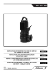
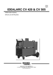
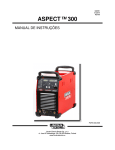
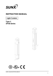
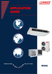
OWNER'S MANUAL
Installation
Operation
Maintenance
Contents
Welcome
1
1
2
3
3
3
4
4
5
5
Safety
6
6
6
7
7
Warranty
General Safety Rules
The Requirement of Personnel
Improper Use
Mechanical Hazards
Electrical Hazards
Bad Weather
Storage Battery
Unloading Resistance
Storage Battery
Hardware Warranty
Restrictions
Disclaimer
Limitation of Liability
8 Specification
9
Wind Driven Generator System
10
Wind Generation Controller
11
Wind Generator Inverter
12
Storage Battery
12
Wires, Joints and Switches
13
14
15
16
17
17
17
Installation
18
Installation of Blades
Installation Guidelines
Slection of Installation Sites
Installation Flow Chart
Requirement of Foundation
Two Towers Connection
Generator Connection
23
24
26
27
28
29
Connections of Rotary Table and Generator
Connections of Tail Rudder and Generator
Installation of Individual Tower Generator
Installation of Generator Controller
Off-grid System Connections
On-grid System Connections
30
Use of Phonowind
30
31
Starting & Shutdown--Off gird
Starting & Shutdown--On gird
32
32
Contents and Frequencies of Maintenance and Overhaul
33
33
Basic Problems and Solutions of Merchanical Parts
Basic Problems and Solutions of Electrical Parts
34
Appendix: A
36
Appendix: B
39
Appendix: C
40
Appendix: D
41
Appendix: E
43
After-sales Service
Maintenance
Welcome
Phonowind
Congratulations on your purchase and welcome to our family!
Dear Phonowind Owner,
Thank you for your purchase of Phonowind. You have just selected the most
technologically advanced, cost-effective renewable energy appliance available for a
home or small business. We congratulate you on your choice and are confident you will
experience years of dependable service.
Before going any further, please complete and return the enclosed Warranty
Registration Card. The conditions of your warranty are dependent upon the
proper installation of Phonowind. Furthermore, this will assure you of being
kept up-to-date with the latest developments from Phonowind. These include new
options, performance tips, updated software to maximize output and user notices. It is
important to know that we do not sell or distribute your information to any third party.
We understand your privacy is important.
If you have any questions or comments, we would like to hear from you. Please call
during working hours (Monday-Friday 09:00 - 15:00 CET).
Our phonenumber is +86 25 58638132
+86 25 58638136
Again, welcome to our family and thank you for investing in the future of wind energy
with Phonowind.
Sincerely,
Phonowind
Enter the serial and model number below
Serial Number
Model Number
Safety
WARNING: Read all instructions. Failure to follow all instructions listed below
may result in electric shock, fire and/or serious injury.
General Safety Rules
1)
SAVE THESE INSTRUCTIONS FOR FUTURE REFERENCE. This manual contains
important instructions for Phonowind that must be followed during installation and
maintenance.
2)
READ and UNDERSTAND all warnings before installation
5)
Install Phonowind in accordance with National Electric Code(NEC) and local
building codes
6)
Always obtain a building permit before construction
7)
Always Use safety equipment. Non-skid safety shoes, hard hat, work gloves and
safety glasses must be used for appropriate conditions. Ordinary eye or sun glasses
are NOT eye protection.
8)
Turn Phonowind "Stop" if ice accumulates on blades to avoid possible injury
resulting from ice blocks dropping from the blades and tail runnder
9)
This wind generator complies with international safety standards and therefore the
design or its installation must never be compromised.
a. Do not change the structure and function of the generator
b. Do not modify the control software.
c. Apply the proper torque to all fasteners.
d. Install only on a Professional Engineer (PE) certified tower.
10) Do not enter the danger area in the process of installation and maintenance.
Workers should circle the danger area with warnings and barries. The danger
area 's diameter is 20m with the tower as the center.
11) Use only proper grounding techniques as established by the NEC
12) Ensure the battery and inverter is swithed off and the generator is in the
stop status before installtion and maintenance
13) Poor Connection and damaged electric cables must be dismantled and
replaced
1
WARNING: Do not approach the generator in the weather of thunderstorm
WARNING: Do not change the battery connection wires when the generator,
controller and inverter work. Please turn off the generator, controller and inverter
before disconnect the battery connection wires.
WARNING: Unloading resistance is the important control brake and overload
unloading protection component in the system and ensure that it connects the
controller effectively. Do not change the unloading resistance connection wires when
the generator, controller and inverter work.
14) Do not insatll the generator in the bad weather or when the wind speed
is over 5m/s
15) Phonowind must be installed in accordance with this manual and local
and national building codes. Failure to comply with the manual and local
codes will affect and possibly void your warranty.
16) Phonowind uses high voltage and is potentially dangerous. Be sure to use
all safety precautions at all times.
The Requirement of Personnel
2
1)
Only the people who have full civil capacities are allowed to do the related work.
2)
Only the designated personnel who have trained by manufacturer, read and got a
good understanding about the manual, can do the installation and maintenance
work of generator.
3)
The work high above the ground can only be done by the well-trained workers
4)
There must be one experienced worker to supervise constantly if the workers who
are undergoing training want to do any operation on the generator.
5)
At least two workers do the generator installation and maintenance work
simultaneously
6)
The personnel's protection: to avoid being hit by the falling objects, the workers
must put on the safety helmets with locking belts when they are working around
the towers. And they must wear the life jackets if the generator is near to the water
sites.
Improper Use
WARNING: The generator cannot work without the controller. If there’s no
controller, make the generator short-circuited. When the controller hasn’t work,
put the Wind Turbine of controller on the place of “Stop”
• Without the manufacturer's written permission, do not change the structure and
function of the generator.
• Do not modify the control software.
• The unqualified personnel are not allowed to do the work of the generator’s
installation and maintenance.
• Phono wind will not be responsible for the losses caused by improper use.
Mechanical Hazards
WARNING: To avoid being hit by the falling objects, do not enter the danger area
in the process of installation and maintenance. Workers should circle the danger
area with warning marks and the red and white barriers. The danger area’s diameter
is 20m with the tower as the center.
• Do not approach the blade and the tail rudder when the generator works.
• In the process of the generator’s installation and maintenance, make sure that the
generator doesn’t work, its output lines are in short circuits and the blade will not
move.
Electrical Hazards
WARNING: Before starting the work of any electrical component’s installation and
maintenance, the generator must enter the "Stop" status and the controller, storage
battery and the inverter are without power. The switch cabinet must have the warning
sign of no starting. Check whether the generator is with power, grounded and in the
status of short circuits or not.
1) Poor connection and damaged electric cables must be dismantled and replaced.
2) To avoid the over load, the connections of the equipment must meet the
requirements of Appendix D.
3) Make the generator stop work if there are some network faults.
3
4) The electrical system must be in the security status. Please refer to the requirements
of Chapter Five to do the regular maintenance work.
5) Only the authorized workers can test the electrical components.
6) The off-grid controller and inverter cannot be directly used with the lines that connect
the electric network.
7) The auxiliary equipment and tools must be insulated. Do check whether there is a
problem before use.
Bad Weather
WARNING: Torrential Rain/Lightning Danger: Do not approach the generator in the
weather of thunderstorm. If it’s in the weather of thunderstorm, the personnel who
are close to the tower must leave at once.
• Before the weather of typhoon / tornado / hurricane / sand storms / earthquakes come,
user should let the generator stop work and put the tower down. The personnel who
are close to the tower must leave at once.
• Under certain climate conditions, the blades will freeze, turn the ponowind "stop", The
blades will not work unbalancedly because of the over weight. And the ice blocks may
drop from the blades
and tail rudder.
• Do not install the generator in the bad weather or when the wind speed is over 5m/s.
Please consult Phono Wind technical personnel first if you have special requests.
Battery
WARNING: Please follow the battery instructions to operate it. Do not change the
battery connection wires when the generator, controller and inverter work. Please
turn off the generator, controller and inverter before disconnect the battery
connection wires.
WARNING: Do connect the battery with the controller before starting the off-grid
generator.
4
Unloading Resistance
WARNING: Unloading resistance is the important control brake and overload unloading
protection component in the system. Ensure that it connects the controller
effectively. Do not change the unloading resistance connection wires when the
generator, controller and inverter work. Do please check whether there is a problem
before use.
Rotating Components
WARNING: Do not approach the blade and the tail rudder when the generator works
High Temperature Mark
WARNING: This mark mentions the temperature of some parts in the controller exceed
65 centigrade, take care and avoid the possibility of burns
Ventilation Mark
WARNING: This mark mentions that the controller use natural heat dissipation method,
pay attention to ventilation
High-Voltage Electric Mark
WARNING: this mark mentions that there is high AC or DC voltage in the controller, the
operator should know the proper practices of high-voltage
5
Warranty
Hardware Warranty
Phonowind will repair or replace free of charge any part or parts of the Phonowind
generator determined by Phonowind to be defective in materials and/or workmanship
under normal authorized use consistent with product instructions for a period of two
years from the date the original purchaser (“Customer”) receives the wind generator
(“Start Date”). This warranty extends only to the original purchaser. The Customer’s sole
and exclusive remedy and the entire liability of Phonowind, its suppliers and affiliates
under the warranty is, at Phonowind’s option, either (i) to replace the wind generator
with new or reconditioned wind generator, (ii) to correct the reported problem, or (iii)
to refund the purchase price of the wind generator. Repaired or replaced products are
warranted for the remainder of the original warranty period.
Restrictions
Problems with the wind generator products can be due to improper use, maintenance,
non-Phonowind additions or modifications or other problems not due to defects in
Phonowind Energy’s workmanship or materials. No warranty will apply if the wind
generator (i) has been altered or modified except by Phonowind, (ii) has not been
installed, operated, repaired, or maintained in accordance with instructions supplied
by Phonowind (iii), or (iv) has been exposed to winds exceeding 40 m/s, or has been
subjected to abnormal physical, thermal or electrical stress, misuse, negligence, or
accident. If Phonowind’s repair facility determines that the problem with the wind
generator is not due to a defect in Phonowind’s workmanship or materials, then the
party requesting warranty service will be responsible for the costs of all necessary repairs
and expenses incurred by Phonowind.
Disclaimer
EXCEPT FOR THE EXPRESSED WARRANTY SET FORTH ABOVE, PHONOWIND DISCLAIMS
ALL OTHER EXPRESSED AND IMPLIED WARRANTIES, INCLUDING THE IMPLIED
WARRANTIES OF FITNESS FOR A PATICULAR PURPOSE, MERCHANTABILITY AND NONINFRINGEMENT. NO OTHER WARRANTY, EXPRESSED OR IMPLIED, WHETHER OR NOT
SIMILAR IN NATURE TO ANY OTHER WARRANTY PROVIDED HEREIN, SHALL EXIST
WITH RESPECT TO THE PRODUCT SOLD UNDER THE PROVISIONS OF THESE TERMS
AND CONDITIONS. PHONOWIND ENERGY EXPRESSLY DISCLAIMS ALL LIABILITY FOR
BODILY INJURIES OR DEATH THAT MAY OCCUR, DIRECTLY OR INDIRECTLY, BY USE OF
THE PRODUCT BY ANY PERSON. ALL OTHER WARRANTIES ARE EXPRESSLY WAIVED BY
THE CUSTOMER.
6
Limitation of Liability
UNDER NO CIRCUMSTANCES WILL PHONOWIND ENERGY OR ITS AFFILIATES OR SUPPLIERS BE
LIABLE OR RESPONSIBLE FOR ANY LOSS OF USE,INTERRUPTION OF BUSINESS, LOST PROFITS,
LOST DATA, OR INDIRECT, SPECIAL, INCIDENTAL, OR CONSEQUENTIAL DAMAGES, OF ANY KIND
REGARDLESS OF THE FORM OF ACTION, WHETHER IN CONTRACT, TORT(INCLUDING NEGLIGENCE),
STRICT LIABILITY OR OTHERWISE, RESULTING FROM THE DEFECT, REPAIR, REPLACEMENT,
SHIPMENT OR OTHERWISE, EVEN IF PHONOWIND ENERGY OR ITS AFFILIATE OR SUPPLIER HAS BEEN
ADVISED OF THE POSSIBILITY OF SUCH DAMAGE.(Note: some states and provinces do not allow the
exclusion or limitation of incidental or consequential damages, so these limitations may not apply to
you). Neither Phonowind nor its affiliates or suppliers will be held liable or responsible for any damage
or loss to any items or products connected to, powered by or otherwise attached to the Hardware. The
total cumulative liability to Customer, from all causes of action and all theories of liability, will be limited
to and will not exceed the purchase price of the product paid by Customer. This Warranty gives the
Customer specific legal rights and the Customer may also have other legal rights that vary from state to
state or province to province.)
7
Introduction
The Phono Wind generator is made of the three-phase permanent direct driving
generator, three blades, the rotary table, the passive yawing tail rudder, rotors, the
tower, the controller and dump load. See system specification table for the specific
parameters.
R
H
Ground Level
Base
Model
8
H
R
Phono W-1.0 (PWB01-30-48)
10m
1.5m
Phono W-2.0 (PWB02-40-48)
10m
2m
Phono W-3.0 (PWA03-44-240)
10m
2.2m
Phono W-5.0 (PWA05-50-240)
10m
2.5m
Phono W-10.0 (PWA10-75-450)
10m
3.75m
Typical Phonowind system installation
On-Grid
AC
Controller
DC
Inverter
AC
Grid
Off-Grid
AC
Controller
DC
DC
DC
Inverter
AC
Grid
DC load
Battery Bank
Off-Grid wind - solar hybird system
AC
DC
Controller
DC load
DC
Battery Bank
Inverter
AC
AC load
DC
Controller
9
DC
DC
Wind Driven Generator System
The wind driven generator system includes the fairing, the rotary table, blades, three-phase permanent
direct driving generator, rotors, the trail cover, the tail rudder rod and the tail rudder.
19, 20, 21
18
14, 15, 16
8
11, 12, 13
22
10
7
9
6
5
23
17
24
25
2
3
4
No.
Item
1
Nosecone
10
Generator
19
Rudder Pole
Bolt
11
Nut
20
Nut
2
3
Item
Spring Washer 12 Spring Washer 21 Spring Washer
4
Plain Washer
13
Plain Washer
22
Plain Washer
5
Nut
14
Nut
23
Rudder Plate
6
10
Item
Spring Washer 15 Spring Washer 24
7
Nut
16
8
Wind Rotor
9
Cotter Pin
Nut
Plain Washer
25
Nut
17
Tall Cover
26
Tower
18
Rudder Plate
Wind Generator Controller
WARNING: The generator controller must match the dump load that conform to the technical data.
• The Phono generator controller changes AC of the generator's output current to DC and protects the
wind driven generator system and the inverter (the battery).
• The Phono generator controller applies only to the Phono generators of the appropriate models. The
principles of the On-grid system and the off-grid system are different.
Off-Grid Turbine
(1KW/2KW)
On-Grid Turbine
(3KW/5KW/10KW)
11
Wind Generator Inverter
• For the inverter, please refer to Appendix B or contact Phono wind for details. Our technicians
will recommend you the suitable inverters that meet the local security standards, electricity network
standards and your use standards. The MPP that the inverters need will also be offered.
• For the installation, use, maintenance and the warranty of the inverters, please refer to instructions or
user manual offered by the inverter suppliers.
Battery
• For the battery, please refer to Appendix C contact Phono for details and our technicians will
recommend you the most suitable solutions.
• For the installation, use, maintenance and the warranty of the battery, please refer to the
instructions offered by the battery suppliers.
Wires, Joints and Switches
• Please refer to Appendix D to choose the wires, power switches and joints that meet the country and
region law and regulations where the generators are used.
12
Installation
WARNING: Do the generator installation, assembly and running work after reading the
complete instructions.
WARNING: Before the installation work, please refer to the packing list to
check whether the generator components are complete.
WARNING: For the off-grid system, workers should prepare the batteries and ground
terminals while the workers should prepare the terminal boxes that connecting with the
power network as well as the terminal boxes for the On-grid system.
Installation Guidelines
13
1)
Keep this manual as the content of this manual is very important. In the process of
assembly, installation and maintenance, do please follow the content.
2)
Please read, understand and take all the warnings seriously.
3)
Do not do the installation work under the bad weather or when the wind speed is
over 5m/s.
4)
Follow the connection requirements in this manual, including the recommended
specifications. Use the wires and the joints that meet the local law and regulations
where the generators are installed.
5)
If you notice the abnormal noise or the situation of the generator, please turn off
the machine and contact the qualified service staff.
6)
When installing the wind driven generator, users must follow the related
regulations of this manual and the nation. If users don’t follow the related
regulations of this manual and the nation, it may influent the warranty of the
products you bought and make it invalidated.
7)
the rotating blades are dangerous. Do make sure that nobody will touch the blades
in the process of the installation.
8)
For the On-grid system, please choose the inverters that match the local network
and you can contact Phono Wind or local dealers to get.
9)
For the unclear problems, please contact Phono Wind or local dealers.
Slection of installation Sites
As each installation is diffrent: the heifht of surrounding structures, wire length, and available open
space, the best place to install a wind turbine is often a compromise.
In general, the wind turbine will produce more power if installed on a taller tower. However, the price of
the tower increase along with the height of tower, so it is important to balance performance to installed
cost in order to achieve the lowest cost of energy and the quickest payback.
Recommendations:
• Install Phonowind 6.5m above any surrounding object within 50m radius
• L ≥ 5D (L: Distance between two towers, D: Rotor's diameter)
TIP: Your dealer can help you to determine
the best location to install Phonowind
Wind Direction
≥ 6.5m
* L: Distance between two towers
D: Wind rotor's diameter
Optimal Phonowind Location
Recommended ambient conditions:
14
Temperature range:
-30°C to +50°C
Humidity condition:
Up to 95%
Recommended elevation value:
Below 3000m
L ≥ 5D
Installation Flow Chart
15
Requirements of Foundation
Pouring the Foundation: Trench the excavation according to the foundation drawing you will use,
blind or weld the ground anchors according to its arranged sizes and then put the ground anchors into
the excavation and start to pour the concrete after arranging the ground anchors well.
As the concrete’s compressive strength is over 32.5Mpa (ISO 679). Users can use the vibrating spear to
make the concrete dense.
After pouring the foundation, users should cover it to do the wet maintenance work and the wet
maintenance period is 200h. The foundation bolts that are above-ground should be painted with the
grease or wrapped with the plastic in case of rusting
Notice: When constructing, users can do the earth terminal work as well. And the resistance to the
ground is ≤4Ω.
Notice: The foundation construction standards should meet the local laws and regulations. Please refer
to the appendix for the foundation construction drawings.
Notice: The foundation soil is very important reference and please consult the civil engineers for the
detailed requirements. It should be in accordance with the foundation drawings and the requirements
of the construction project.
Two Towers Connection
16
1)
Following the drawing, use the crane to put the two towers together and align the middle flanges.
2)
Use the bolts to connect the two tower flanges. Please refer to Appendix A for the specifications
and the moment of force of bolts.
3)
Let the wires go through the tower and connect the cable row of the tower bottom. Let the cable
row be in the status of “On” (short-circuit condition) and prevent the blades from rotating stall.
4)
Secure the tower to good ground and the ground resistance value is ≤4Ω.
Generator Connection
17
1)
Use the crane to hoist the generator and Keep the top of the tower on the same plane.
2)
Make the lines go through the tower and the lines should 200-250mm longer than the installation
of the tower and generator. Place the lines in the lifting hook of the generator installation’s tower
inner bore.
3)
Use the crane to hoist the motor, connect the lines of the tower with the outgoing lines of the
motor and wrap them with sello tapes.
4)
Use the bolts to connect the tower’s top flange with the rotary flange.
5)
Please refer to Appendix B for the specifications and moment of force of the bolts
Installation of Blades
18
1)
Lock six bolts to the wind roulette and the side B of rear hub faces up.
2)
Let the side B of the blade root face down, install them on the blade sockets and use the hammer
to tap lightly to make the bolts close to the blade sockets. The blade side A faces the wind roulette
side A while the blade Side B faces blade socket side B. Install another two blades as this way. Use
the rubber hammer to tap the three blade roots to the wind roulette bottoms.
3)
Install the front hub on the rear hub.
4)
Screw the nuts with hands but don’t tighten them.
5)
Turn over the whole wind rotor and screw another 9 bolts.
6)
Turn over the wind rotor again, measure the distance of the blades as the common difference
should be ±3mm to make sure that the angle of the three blades is 120°.
7)
After the measurements and adjusting, install the plain washers and spring washers of the bolts
and tighten the nuts.
8)
Please refer to Appendix B for the specifications and moment of forces of the bolts.
Notice: do add the spring washer and the plain washer to each bolt, tighten them and keep the
moment of force same.
A
B
19
Step 1
B
Step 2
A
A
A
Step 3
20
Step 4
Overturn
Step 5
Overturn
Step 6
21
L1
L2
L3
L1=L2=L3±3mm
22
Connections of Rotary Table and Generator
Put the installed wind rotor to the to motor shaft, fix it with nuts, plain washer, spring washer and cotter
pin. Install the nose cone and fix it with bolts. Use three screws, connecting bolts, flat washers and
spring washers to fix the nose cone on the wind rotor. Please refer to Appendix B for the specifications
and moment of forces of the bolts.
WARNING: When installing, keep the wiring short circuit switch on, which is on the bottom of the
tower; or to avoid the accidents causing because of the wind rotor's rotating, make the three-phase
wires of generator be in short circuit status.
Wind Rotor
Nose Cone
Cotter Pin
Motor Shaft
23
Connections of Tail Rudder and Generator
24
1)
Fix the tail rudder plate to the tail rudder plate and tighten the bolts.
2)
put the tail cover through rudder pole
3)
connect the rudder pole and rudder seat with bolts, nut, spring washers and plain washers.
4)
connect tail cover and rudder flange with bolts, nut, spring washers and plain washers.
Connections of Tail Rudder and Generator
Step 1
Step 2
Step 3
Step 4
25
Installation of Individual Tower Generator
For the independent tower, it needs the 3 tons crane to lift it up, the tower rod should be placed leveled
and use the stand to support and tighten the base’s bolts after lifting. Fix the top of the tower when
lifting and workers can disassemble the ropes.
The professional crane operators lift the tower and the wind driven generator up with the crane. The
hanging strips but not the steel wire ropes can be used and in the process of lifting, the hanging strips
should be tied to below the top flange of the tower.
Pay attention to the protection of the blades.
After lifting the tower, adjust its position to make the hole under the flange be directed at the
foundation’s ground anchor and then gradually put all the ground anchors in the holes. Install the
washer and the bolt, tighten them and add some solid lubricant to protect it from corrosion. Please refer
to the Appendix B for the bolts’ specifications and moment of forces.
Do please lay down the tower under the no wind weather and prepare a support(same to the one used
in installation).
ground
anchor
Flange
Ground
base
Ground
26
Flange
The Installation of Generator Controller
The controller dimensions are as follows:
a
TYPE
a/mm b/mm c /mm
Phono
440
W-1.0, 2.0
Phono
W-3.0,
5.0, 10.0
550
570
250
650
250
b
c
The controller’s installation is as follows:
• Choose the solid wall to punch and fix the controller’s support.
• Fix the controller on the support and tighten the fixed bolt, which is in the bottom.
Cable Recommended Configuration
(from tower to controller)
2KW/5kw/10kw
1KW/3kw
UL
4X12 AWG
105° C
600V
4X10 AWG
105° C
600V
CE
4X4mm2
105° C
300/500V
4X6mm2
105° C
300/500V
Note: PHONO WIND will not provide the cable from tower to controlle
Users can purchase cable by above recommended information
27
Off-grid System Connections
AC
DC
Controller
DC
DC
AC
Inverter
Grid
DC load
Battery Bank
Read
Normal
Brake
Brake
STOP
On
Off
Normal
Wind Input
Wind Turbine
Wind Turbine
28
G
A B C
Inverter
+ -
DC>AC
Off-gird
Inverter
Battery
+ -
Battery
Dump load
+ -
GND
┻
〓
Battery
R
AC LOAD
1)
When connecting the wires, do it according to the order from right to left.
2)
When connecting the wires, make the Wind Turbine be in the status of “stop” and the Battery Onoff is in that of “Off”.
3)
Please refer to Appendix C for the inverter and battey’s allocations or contact Phono Wind.
4)
Please refer to Appendix D for the cable’s specifications.
On-grid System Connections
AC
1)
Controller
DC
Inverter
AC
Grid
When connecting the wires, do it according to the order from right to left.
2) When connecting the wires, make the Wind Turbine be in the status of “stop” and the Gird is in
that of “Off”.
29
3)
Please refer to Appendix C for the inverter allocations or contact Phono Wind.
4)
Please refer to Appendix D for the cable’s specifications.
Use of Phonowind
Starting: Off-gird
1)
Make sure finishing installation according to above procedures and any parts of
wind driven generator in good condition.
2)
Switch on controller, push up Batter on-off to ‘ON’, then the controller Display
starts to work, displaying Battery Voltage normal range should be 42-60, if not,
please check storage battery and wiring.
3)
After 30 seconds, turn BRAKE right at ‘Normal’, push up Wind turbine at ‘Normal’,
wind driven generator will start to work. If now Wind speed≥2.5m/s, system will
start to generate electricity.
Notice: When wind driven generator first starts after installation, suggests run
system at wind speed ≤5m/s
Read
Normal
Brake
Brake
STOP
On
Off
Normal
Wind Input
Wind Turbine
A B C
Inverter
+
-
Battery
+ -
Dump load
+
-
GND
┻
〓
Battery
Shut Down
When wind speed ≤10m/s, press BRAKE switch at ‘Brake’, then controller Display will
display voltage reduce to’ LOCK’, at that time, the wind wheel rotating speed slow
down obviously, then push down Wind turbine at ‘STOP’, wind driven generator will
stop working.
30
Starting Up Process
Check turbine
status
Switch on
battery
Shut Down Process
Check outside
wind speed
Turn "Brake" to
Brake status
Emergency shut Down Process
Turn "Brake" to
Brake status
Turn "Brake" to
Normal status
Press STOP
button
Press STOP
button
Starting: On-gird
1)
Make sure finishing installation according to above procedures and any parts of
wind driven generator in good condition.
2)
Switch on controller, pon power on, then the controller Display starts to work,
displaying"stop" , if not, please check Gird and wiring.
3)
After 30 seconds, turn BRAKE right at ‘Normal’, push up Wind turbine at ‘Normal’,
wind driven generator will start to work. If now Wind speed≥2.5m/s, system will
start to generate electricity.
Notice: When wind driven generator first starts after installation, suggests run
system at wind speed ≤5m/s
Shut Down
When wind speed ≤10m/s, press BRAKE switch at ‘Brake’, then controller Display will
display voltage reduce to’ LOCK’, then push up Wind turbine at ‘STOP’, wind turbine will
stop working.
31
Starting Up Process
Check turbine
status
Switch on
controller
Turn "Brake" to
Normal status
Shut Down Process
Check outside
wind speed
Turn "Brake" to
Brake status
Press STOP
button
Emergency shut Down Process
Turn "Brake" to
Brake status
Press STOP
button
Maintenance
Contents and Frequencies of Maintenance and Overhaul
32
No.
Items
Checking
method
1
Generator tail rudder
vibrate abnormal
Vision check
Tail rudder vibrate dramatically in
vertical direction
3 years
2
Generator has
abnormal noise
Ears to hear
(keep distance
10m to tower)
Abnormal noise, intermittently and
big noise
3 years
3
Yaw
Vision check
Wind speed≤8m/s yaw
Wind speed≥13m/s normal
Yaw slowly or stuck
3 years
4
Electrical wiring
Vision check
Come off, burnt
1 year
5
Controller display
panel
Vision check
Abnormal flashing, no display
1 year
6
Bearing lubrication
Vision check
Starting slow and turning slow
1 year
7
Bolt
Torque wrench
Loose or less than torque regulated
1 year
8
Fan blade
Vision check
Flaw, crack
1 year
9
Generator set
appearance
Vision check
Flaw
2 years
10
Tail rudder shaft
Vision check
Wear down
1 year
11
Tail rudder plate
Vision check
Flaw
1 year
At working time, three phrase voltage
difference is greater than voltage value
of 5% no-working time, three phrase
resistance is not equal
1 year
Breakdown phenomenon
Frequency
12
Generator output
Multimeter
13
Controller output
Multimeter
No diode characteristic
1 year
14
Unloading resistance
Multimeter
More than 20% difference with nominal
resistance
1 year
15
Resistance to earth
Multimeter
Tower, controller shell resistance to
earth is more than 10Ω
1 year
Basic Problems and Solutions of Merchanical Parts
Breakdown
Cause
Solution
Wind driven generator
shake dramatically
• Wind blade loose
• Blade deform or defect
• Tower bolt loose
• Tighten loose part and adjust
• Adjust or change blade
• Tighten loose part
Rotor speed reduces
significantly
• Generator lacks of lubrication or
maintenance.
• Generator bearing broken
• Rotor blade broken
• Lubricate
• Exchange
• Repair or exchange
Speed governing and
direction governing
ineffective
Abnormal noise
•
•
•
•
Rotary bearing lacks grease oil.
Rotary inside has sand or foreign matter.
Tower deform( upper end)
Tail shaft rudder inside has foreign matter,
wear down or lack of grease oil.
•
•
•
•
Lubricate, maintenance
Clear up, lubricate, maintain
Correct
Clear up, lubricate, maintain
•
•
•
•
Parts loose
Bearing broken
Generator stator and rotor friction
Blade frozen or broken
•
•
•
•
Tighten
Exchange
Change bearing and correct
Clean up and exchange
Basic Problems and Solutions of Electrical Parts
Breakdown
LED display panel no display
Cause
System is not at work or LED wiring loose
Solution
Reconfirm the wiring
BRAKE has no LED, or did not The BRAKE button wiring no good or BEAKE
indicate ‘STOP’
broken
Check the wiring or exchange
BRAKE button
LED has no ‘STOP’ or ‘DXXX’
indication, DUMP LOAD still
heating
Resistance is still in heat state
Ignore
Unload IGBT at short- circuit
Contact the local dealer or
Phono wind
Storage capacity is small
Exchange allocation
DC/DC mold malfunction
Contact to local dealer or
Phono wind.
Off-grid system, the storage
battery voltage is higher than
60v
Unloading IGBT at short- circuit
In corresponding wind speed,
wind driven generator rotate
slow, obviously abnormal
DC/DC mold malfunction
Contact to dealer or Phono wind.
Wind driven generator wire short-circuit
LED has Err mark
33
Now the wind driven generator output
voltage or power abnormal, in protection
alarm status
Waiting for the wind become small,
return to work.
Appendix A: Specification
System Specification
Project
Phono W - 1.0
Phono W - 2.0
Phono W - 3.0
Phono W - 5.0
Phono W - 10.0
Model No.
PWB01-30-48
PWB02-40-48
PWA03-44-250
PWA05-50-280
PWA10-75-450
Wind Rotor's Diameter
3m
4m
4.4m
5m
7.5m
Blade Quantity
3
3
3
3
3
Yaw
Mechanic
Mechanic
Mechanic
Mechanic
Mechanic
Inlet Air Way
horizontal axis,
upwind
horizontal axis,
upwind
horizontal axis,
upwind
horizontal axis,
upwind
horizontal axis,
upwind
Stop Way
Manual
Manual
Manual
Manual
Manual
Cut-in Wind Speed
3 m/s
3 m/s
3 m/s
3 m/s
3 m/s
Cut-out Wind Speed
18 m/s
18 m/s
18 m/s
18 m/s
18 VDC
Rated Wind Speed
10 m/s
10 m/s
10 m/s
11 m/s
11 m/s
Survival Wind Speed
40 m/s
40 m/s
40 m/s
40 m/s
40 m/s
Cut-in Voltage
37.5 VDC
37.5 VDC
50 VDC
50 VDC
50 VDC
Rated Output Voltage
48 VDC
48 VDC
250 VDC
280 VDC
450 VDC
Rated Power
1 Kw
2 Kw
3 Kw
5 Kw
10 Kw
Rated Speed
380 rpm
330 rpm
330 rpm
280 rpm
190 rpm
34
Appendix: A: Specification
Turbine Specification
Project
Phono W - 1.0
Phono W - 2.0
Phono W - 3.0
Phono W - 5.0
Phono W - 10.0
Model No.
PWG01-10-90
PWG02-10-90
PWG03-10-180
PWG06-16-220
PWG11-20-420
Generator Type
Three-phase
PMSM
Three-phase
PMSM
Three-phase
PMSM
Three-phase
PMSM
Three-phase
PMSM
Nominal Line Voltage
90 VAC
90 VAC
180 VAC
220 VAC
420 VAC
Nominal Line Current
6.7A
13A
10A
16A
15A
Rated Frequency
31.66
27.5
27.5
37.33
31.66
Insulation Grade
A
A
A
A
A
Protection Grade
IP54
IP54
IP54
IP54
IP54
Blade Mass (kg)
3.58
8.45
10
14.4
46
Rotor Mass (kg)
18.74
46.11
50.76
63.6
227.87
Turbine Mass (kg)
92.5
132
150
282
700
Tower Mass (kg)
320
480
480
585
870
Wind turbine controller Specification
Project
Phono W - 1.0
Phono W - 2.0
Phono W - 3.0
Phono W - 5.0
Phono W - 10.0
Model No.
PWC01-B-48
PWC02-B-48
PWC03-A-250
PWC06-A-280
PWC11-A-450
System Voltage Grade
(VDC)
48 VDC
48 VDC
250 VDC
280 VDC
450 VDC
Output Voltage Range
(VDC)
42 - 60 VDC
42 - 60 VDC
0 - 260 VDC
0 -290 VDC
0 - 450 VDC
Generator Rated Power
(KW)
1
2
3
6
11
Rectifier DC(A)
16
32
12.5
22
25
Manual Brake
YES
YES
YES
YES
YES
Automatic Unloading
YES
YES
YES
YES
YES
Protection Grade
IP54
IP54
IP54
IP54
IP54
NEMA Type
Type 3
Type 3
Type 3
Type 3
Type 3
35
Appendix: B Phono w-1.0
Wind Driven Generator Bolt Connections (Phono W - 1.0)
No.
Joint
Quantity
Specification
Grade
Force
(N•M)
Nut
Measurement
1
Rudder Pole
&
Rudder Plate
3
M10×40
8.8
25
16mm
2
Blades & Hub
15
M10×90
8.8
50
16mm
3
Motor Shaft
1
M24
/
750
36mm
4
Rudder Axis
1
Φ 25
/
150
/
5
Nose Cone,
Tail Cover
3 for each type
M8×20
8.8
15
Hexagon Wrench
6#
6
Turbine & Tower
6
M12×55
8.8
90
18mm
Connection Torque Table of Towers and Bolts (Phono W - 1.0)
No.
1
2
36
Joint
Bottom Flange
Tower Middle
Flange
Quantity
8
8
Specification
M24
M20×80
Grade
Force
(N•M)
Nut
Measurement
8.8
750
36mm
8.8
450
30mm
Appendix: B Phono w-2.0
Phono w-3.0
Wind Driven Generator Bolt Connections (Phono W - 2.0,3.0)
No.
Joint
Quantity Specification
Grade
Nut
Force
(N•M) Measurement
1
Rudder Pole
&
Rudder Plate
3
M10×60
8.8
25
18mm
2
Blades & Hub
15
M16×120
8.8
100
24mm
3
Motor Shaft
1
M24
/
750
36mm
4
Rudder Axis
1
Φ 25
/
150
/
5
Nose Cone,
Tail Cover
3 for each
type
M8×20
8.8
15
Hexagon Wrench
6#
6
Turbine & Tower
6
M16×60
8.8
220
24mm
Connection Torque Table of Towers and Bolts (Phono W - 2.0,3.0)
No.
1
2
37
Joint
Bottom Flange
Tower Middle
Flange
Quantity Specification Grade
Force
(N•M)
Nut
Measurement
8
M24
8.8
750
36mm
8
M20×80
8.8
450
30mm
Appendix: B Phono w-5.0
Wind Driven Generator Bolt Connections(Phono w-5.0)
No.
Joint
Quantity Specification
Grade
Nut
Force
(N•M) Measurement
1
Rudder Pole
&
Rudder Plate
3
M12×75
8.8
50
18mm
2
Blades & Hub
15
M16×140
8.8
100
24mm
3
Motor Shaft
1
M36
/
1600
56mm
4
Rudder Axis
1
Φ 30
/
150
5
Nose Cone,
Tail Cover
3 for each
type
M8×20
8.8
15
Hexagon Wrench
6#
Connection Torque Table of Towers and Bolts(Phono w-5.0)
No.
1
2
38
Joint
Bottom Flange
Tower Middle
Flange
Quantity Specification Grade
Force
(N•M)
Nut
Measurement
12
M30
8.8
1200
46mm
8
M20×80
8.8
450
34mm
Appendix: c
Standard Configurations of Storage Battery and the Inverter
Wind Turbine
Type
Controller
Phono W-1.0
(PWB01-30-48)
Off-gird
PWC01-B-48
Phono W-2.0
(PWB02-40-48)
Off-gird
PWC02-B-48
Input: DC42-60V,
Output: 2000W/KVA
Phono W-3.0
(PWA03-44-250)
On-gird
PWC03-A-250
PVI-3.0-OUTD-W
/
On-gird
PWC06-A-280
PVI-6.0-OUTD-W
/
On-gird
PWC11-A-450
PVI-10.0-OUTD-W
/
Phono W-5.0
(PWA05-50-280)
Phono W-10.0
(PWA10-75-450)
39
Inverter
Input: DC42-60V
Output:1000W/KVA
Battery
48V
150AH
48V
300AH
Appendix: D
Main circuit connecting cable diameters
1 Kw
2 Kw
Project
Description
Maximum
Current
Cable
Maximum
Current
Cable
Maximum
Current
Cable
Generator Output
(connection distance ≤100m)
Wind generator
input AC
8A
4mm2×4
16A
6mm²×4
12
4mm²×4
Controller Output
(connection distance ≤20M)
DC output
(+,-)
20A
6mm²×2
35A
6mm²×2
15
6mm²×2
Controller Unloading
(connection distance ≤20m)
Diversion Load
24A
6mm²×2
45A
6mm²×2
24
6mm²×2
Controller Input
(connection distance≤30m)
L,N
/
/
/
/
0.2
2mm²×2
Ground Connection
(connection distance≤50m)
Connect to ground
/
6mm²×1
/
6mm²×1
/
6mm²×1
5 Kw
40
3 Kw
10 Kw
Project
Description
Maximum
Current
Cable
Maximum
Current
Cable
Generator Output
(connection distance ≤100m)
Wind generator
input AC
20
6mm²×4
20
6mm²×4
Controller Output
(connection distance ≤20M)
DC output
(+,-)
24
6mm²×2
24
6mm²×2
Controller Unloading
(connection distance ≤20m)
Diversion Load
30
6mm²×2
29
6mm²×2
Controller Input
(connection distance≤30m)
L,N
0.2
2mm²×2
0.2
2mm²×2
Ground Connection
(connection distance≤50m)
Connect to ground
/
6mm²×1
/
6mm²×1
Appendix: E
Setting Tools
Tower Hoisting
Project
Item
Spec
Quantity
Application
Remarks
Use the 5-ton truck to
hoist
5T, ≥15M
1
Complete Machine
Hoisting
450 VDC
Hydraulic Station
15mpa, Stoke:1m
1
The installation of
Hydraulic Tower
only applied to the
Hydraulic Tower
Lifting Appliance and the Support
Project
Item
Spec
Quantity
Application
Remarks
Support
Height:1.5M, Loadbearing :2T
1
Supporting the
tower
/
Nylon Slings
2T 6M
2
Listing the wind
rotor
/
Steel Wire Ropes
φ14mm, 10M
1
Lifting
/
Tower Assembling
Project
Item
Spec
Quantity
Application
Remarks
Adjustable Spanners
The maximum
opening =46mm
2
The tower’s basic
installation
5KW
Adjustable Spanners
The maximum
opening =36mm
2
The tower’s basic
installation
1-3KW
Hammer
12 pounds
1
Adjusting the
tower
/
Remarks
Supportive Materials
Project
41
Item
Spec
Quantity
Application
Thread Locking Glue
/
1
Tightening the
bolts
Hand Painting
Galvanized: white
Galvanized:1bottle
Repair the surface
White: 1 bottle
Appendix: E
Wind Driven Generator Assembly Tools
Lifting Appliance
Project
Item
Spec
Quantity
Application
Nylon Slings
2T, 6M
2
Lifting the
Remarks
Spanners
Project
Item
Spec
Quantity
Application
Remarks
Offset Ring Spanners
16#/18#
16#: 1pcs
Tail rudder plate
/
Adjustable Spanners
12 inches
2
Connecting the
generator with the
tower
/
Torque Spanners
Sockets 16# / 18#/ 24#
16#:1pcs
18#:1pcs
24#:1pcs
blades
/
Allen Wrenches
6# 8#
2
Cowls, tail cover
/
Other Tools
Project
Item
Spec
Quantity
Application
Remarks
Crow Bars
φ25 length: 1m
1
the installation of
Tower
/
Hammers
8 pounds
1
the installation of
Tower
/
Rubber Hammers
8pounds
1
Tail rudder plate
/
Measuring Tool
Project
42
Item
Spec
Quantity
Application
Remarks
Multimeters
Universal
1
Check after installation
/
Tape Measures
10m
1
Measuring the distance
of the blade tips
/
Infrared Levels
/
1
Measuring the
verticality of the towers
/