1
User Manual
Basic Configuration
EAGLE20/30
RM GUI EAGLE20/30
Release 1.0 09/2012
Technical Support
https://hirschmann-support.belden.eu.com
The naming of copyrighted trademarks in this manual, even when not specially indicated, should
not be taken to mean that these names may be considered as free in the sense of the trademark
and tradename protection law and hence that they may be freely used by anyone.
© 2012 Hirschmann Automation and Control GmbH
Manuals and software are protected by copyright. All rights reserved. The copying, reproduction,
translation, conversion into any electronic medium or machine scannable form is not permitted,
either in whole or in part. An exception is the preparation of a backup copy of the software for
your own use. For devices with embedded software, the end-user license agreement on the
enclosed CD applies.
The performance features described here are binding only if they have been expressly agreed
when the contract was made. This document was produced by Hirschmann Automation and
Control GmbH according to the best of the company's knowledge. Hirschmann reserves the right
to change the contents of this document without prior notice. Hirschmann can give no guarantee
in respect of the correctness or accuracy of the information in this document.
Hirschmann can accept no responsibility for damages, resulting from the use of the network
components or the associated operating software. In addition, we refer to the conditions of use
specified in the license contract.
You can get the latest version of this manual on the Internet at the Hirschmann product site
(www.hirschmann.com).
Printed in Germany
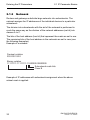
Hirschmann Automation and Control GmbH
Stuttgarter Str. 45-51
72654 Neckartenzlingen
Germany
Tel.: +49 1805 141538
Rel. 1.0 - 09/2012 – 21.9.12
Contents
Contents
About this Manual
7
Key
9
Introduction
11
1
Access to the user interfaces
13
1.1
Command Line Interface
14
1.2
Web-based Interface
17
1.3
Authentication List
1.3.1 Authentication method
1.3.2 Access Applications
20
20
20
1.4
User Management
1.4.1 Privilege Levels
1.4.2 Establishing new user accounts
1.4.3 Disabling user accounts
1.4.4 Passwords for Web access
21
21
23
24
24
1.5
RADIUS Server
1.5.1 Authentication Server
26
27
2
Entering the IP Parameters
29
2.1
IP Parameter Basics
2.1.1 IP Address (Version 4)
2.1.2 Netmask
2.1.3 Classless Inter-Domain Routing
30
30
32
36
2.2
Entering IP parameters via CLI
37
2.3
Entering the IP Parameters via HiDiscovery
40
2.4
Web-based IP Configuration
43
3
Configuration Management
45
3.1
Loading settings
3.1.1 Loading from the local non-volatile memory
3.1.2 Loading from a file
3.1.3 Resetting the configuration to the state on delivery
46
47
47
48
RM GUI EAGLE20/30
Release 1.0 09/2012
3
Contents
3.2
Saving settings
3.2.1 Saving locally
3.2.2 Saving on a PC
49
49
50
4
Loading Software Updates
51
4.1
Loading the Software via File Selection
52
4.2
Software update via SFTP/SCP
53
5
Configuring the Ports
55
6
Assistance in the Protection from Unauthorized
Access
57
6.1
Handling unauthorised accesses
58
6.2
SNMPv1/v2 Community
6.2.1 Description of SNMPv1/v2
6.2.2 Entering the SNMPv1/v2 name
59
59
60
6.3
Access to the device
6.3.1 Description of SSH Access
6.3.2 Description of HTTPS Access
61
61
62
6.4
IP Access Restriction
63
6.5
Access Control Lists
6.5.1 IPv4 Name
6.5.2 IPv4 Rule
6.5.3 MAC Name
6.5.4 MAC Rule
6.5.5 Port Assignment
6.5.6 VLAN Assignment
66
68
69
70
71
73
74
6.6
HiDiscovery Access
6.6.1 Description of the HiDiscovery Protocol
6.6.2 Enabling/disabling the HiDiscovery Function
75
75
75
6.7
Session Timeouts
6.7.1 CLI and Web session
76
76
6.8
Pre-login Banner
6.8.1 Banner Text
78
78
7
Controlling the Data Traffic
79
7.1
Packet Filter
7.1.1 Description of the Packet Filter Function
7.1.2 Application Example for Packet Filter
80
80
83
4
RM GUI EAGLE20/30
Release 1.0 09/2012
Contents
7.2
NAT – Network Address Translation
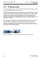
7.2.1 IP Masquerading
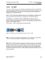
7.2.2 1:1 NAT
7.2.3 Port forwarding
7.2.4 NAT Application Examples
87
88
89
92
93
7.3
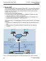
Helping protect against Denial of Service (DoS)
99
8
Synchronizing the System Time in the Network
8.1
Entering the Time
102
8.2
NTP
8.2.1
8.2.2
8.2.3
8.2.4
103
103
104
105
108
9
Network Load Control
9.1
Direct Packet Distribution
9.1.1 Store and Forward
9.1.2 Multi-Address Capability
9.1.3 Aging of Learned Addresses
9.1.4 Entering Static Addresses
112
112
113
113
114
9.2
QoS/Priority
9.2.1 Description of Prioritization
9.2.2 VLAN tagging
9.2.3 IP ToS / DiffServ
9.2.4 Management prioritization
9.2.5 Handling of Traffic Classes
9.2.6 Setting prioritization
116
116
116
119
121
122
123
9.3
Flow Control
9.3.1 Description of Flow Control
9.3.2 Setting the Flow Control
124
124
126
9.4
VLANs
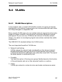
9.4.1 VLAN Description
9.4.2 Examples of VLANs
127
127
128
10
Operation Diagnosis
Description of NTP
Preparing the NTP configuration
NTP Configuration
Multicast Groups
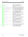
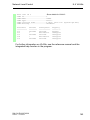
10.1 Sending Traps
10.1.1 List of SNMP traps
10.1.2 SNMP Traps when Booting
10.1.3 Configuring Traps
RM GUI EAGLE20/30
Release 1.0 09/2012
101
111
145
146
147
148
148
5
Contents
10.2 Monitoring the Device Status
10.2.1 Events which can be monitored
10.2.2 Configuring the Device Status
10.2.3 Displaying the Device Status
150
151
151
152
10.3 Out-of-band Signalling
10.3.1 Controlling the Signal Contact
10.3.2 Monitoring the Device Status via the Signal Contact
10.3.3 Displaying detected loss of connection
153
154
155
157
10.4 Port Status Indication
158
10.5 Event Counter at Port Level
10.5.1 Detecting Non-matching Duplex Modes
159
161
10.6 Displaying the SFP Status
163
10.7 Reports
164
10.8 Syslog
166
10.9 System Log
167
10.10 Selftest Dialog
168
A
Setting up the Configuration Environment
A.1
Preparing access via SSH
A.1.1 Generating a key
A.1.2 Uploading the key
A.1.3 Access through an SSH
170
170
171
172
A.2
HTTPS Certificate
A.2.1 HTTPS Certificate Management
A.2.2 Access through HTTPS
174
174
176
B
General Information
B.1
Management Information Base (MIB)
178
B.2
Abbreviations used
181
B.3
Technical Data
182
B.4
Maintenance
183
B.5
Readers’ Comments
184
C
Index
187
D
Further Support
189
6
169
177
RM GUI EAGLE20/30
Release 1.0 09/2012
About this Manual
About this Manual
The “Basic Configuration” user manual contains the information you need to
start operating the device. It takes you step by step from the first startup
operation through to the basic settings for operation in your environment.
The following thematic sequence has proven itself in practice:
Set up device access for operation by entering the IP parameters
Check the status of the software and update it if necessary
Load/store any existing configuration
Configure the ports
Set up protection from unauthorized access
Optimize the data transmission with network load control
Synchronize system time in the network
Perform an operation diagnosis
Store the newly created configuration in the non-volatile memory.
The “GUI” reference manual contains detailed information on using the
graphical interface to operate the individual functions of the device.
The “Command Line Interface” reference manual contains detailed
information on using the Command Line Interface to operate the individual
functions of the device.
The “Installation” user manual contains a device description, safety
instructions, a description of the display, and the other information that you
need to install the device.
RM GUI EAGLE20/30
Release 1.0 09/2012
7
About this Manual
The Industrial HiVision Network Management Software provides you with
additional options for smooth configuration and monitoring:
8
Simultaneous configuration of multiple devices
Graphic interface with network layout
Auto-topology discovery
Event log
Event handling
Client/server structure
Browser interface
ActiveX control for SCADA integration
SNMP/OPC gateway.
RM GUI EAGLE20/30
Release 1.0 09/2012
Key
Key
The designations used in this manual have the following meanings:
List
Work step
Subheading
Link
Note:
Cross-reference with link
A note emphasizes an important fact or draws your attention to a dependency.
Courier ASCII representation in user interface
Execution in the Graphical User Interface (Web-based Interface user interface)
Execution in the Command Line Interface user interface
Symbols used:
WLAN access point
Router with firewall
Switch with firewall
Router
Switch
RM GUI EAGLE20/30
Release 1.0 09/2012
9
Key
Bridge
Hub
A random computer
Configuration Computer
Server
PLC Programmable logic
controller
I/O Robot
10
RM GUI EAGLE20/30
Release 1.0 09/2012
Introduction
Introduction
The device has been developed for use in a harsh industrial environment.
Accordingly, the installation process has been kept simple. Thanks to the
selected default settings, you only have to enter a few settings before starting
to operate the device.
Note: The changes you make in the dialogs are copied into the volatile
memory of the device when you click on "Set".
To save the changes to the device into permanent memory, select the saving
location in the Basic Settings:Load/Save dialog box and click on "Save".
RM GUI EAGLE20/30
Release 1.0 09/2012
11
Introduction
12
RM GUI EAGLE20/30
Release 1.0 09/2012
Access to the user interfaces
1 Access to the user interfaces
The device provides you 2 user interfaces, which can be accessed through
different interfaces:
Command Line Interface (CLI) via the V.24 connection (out-of-band) and
via SSH (in-band)
Web-based interface via Ethernet (in-band).
RM GUI EAGLE20/30
Release 1.0 09/2012
13
Access to the user interfaces
1.1 Command Line Interface
1.1 Command Line Interface
The Command Line Interface enables you to use the functions of the device
via a local or remote connection.
The Command Line Interface provides IT specialists with a familiar
environment for configuring IT devices.
The script compatibility of the Command Line Interface enables you, among
other things, to feed multiple devices with the same configuration data, to
create and use partial configurations, or to compare 2 configurations using 2
script files.
You will find a detailed description of the Command Line Interface in the
“Command Line Interface” reference manual.
You can access the Command Line Interface via:
the V.24 port (out-of-band)
SSH (in-band)
Note: To facilitate making entries, the CLI gives you the option of
abbreviating keywords. Type in the beginning of a keyword. When you press
the tab key, the CLI finishes the keyword.
Opening the Command Line Interface
Connect the device via V.24:
Connect the device with a terminal or with a "COM" port of a PC
with terminal emulation based on VT100.
Press a button on the keyboard.
or
Call the Command Line Interface via SSH.
Users can access the Command Line Interface simultaneously with up
to 5 sessions.
14
RM GUI EAGLE20/30
Release 1.0 09/2012
Access to the user interfaces
1.1 Command Line Interface
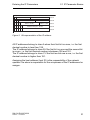
A window appears on the screen for the entry of the user name.
Copyright (c) 2011-2012 Hirschmann Automation and Control GmbH
All rights reserved
EAGLE Release HiOS-01.0.00
(Build date 2012-04-20 11:12)
System Name
Management-IP
Subnet Mask
Base-MAC
System Time
:
:
:
:
:
EAGLE-ECE5550113E0
10.0.1.105
255.255.255.0
00:80:63:4A:A7:B3
2012-04-25 06:11:23
User:
Figure 1: Logging in to the Command Line Interface program
Enter a user name. The default setting for the user name is admin .
Press the Enter key.
Enter the password. The default setting for the password is private .
Press the Enter key.
You can change the user name and the password later in the
Command Line Interface.
Please note that these entries are case-sensitive.
RM GUI EAGLE20/30
Release 1.0 09/2012
15
Access to the user interfaces
1.1 Command Line Interface
The start screen appears.
NOTE: Enter '?' for Command Help. Command help displays all options
that are valid for the particular mode.
For the syntax of a particular command form, please
consult the documentation.
(EAGLE) >
Figure 2: CLI screen after login
16
RM GUI EAGLE20/30
Release 1.0 09/2012
Access to the user interfaces
1.2 Web-based Interface
1.2 Web-based Interface
The user-friendly Web-based interface gives you the option of operating the
device from any location in the network via a standard browser such as
Mozilla Firefox or Microsoft Internet Explorer.
As a universal access tool, the Web browser uses an applet which
communicates with the device via the Simple Network Management Protocol
(SNMP).
The Web-based interface allows you to graphically configure the device.
System requirements
To open the graphical user interface, you need a Web browser, for
example Mozilla Firefox version 3.5 or later, or Microsoft Internet Explorer
version 6 or later.
Installation
Note: The graphical user interface uses Java 6 or Java 7.
Install the software from the enclosed CD-ROM. To do this, you go to
“Additional Software”, select Java Runtime Environment and click on
“Installation”.
RM GUI EAGLE20/30
Release 1.0 09/2012
17
Access to the user interfaces
1.2 Web-based Interface
Starting the graphic user interface
The prerequisite for starting the graphical user interface, first configure
the IP parameters of the device correctly. The “Basic Configuration” user
manual contains detailed information that you need to define the IP
parameters.
Start your Web browser.
Activate Java in the security settings of your Web browser.
Establish the connection by entering the IP address of the device
which you want to administer via the Web-based management in the
address field of the Web browser. Enter the address in the following
form:
https://xxx.xxx.xxx.xxx
The login window appears on the screen.
Figure 3: Login window
Select the user name and enter the password.
Select the language in which you want to use the graphic user
interface.
Click on OK.
18
RM GUI EAGLE20/30
Release 1.0 09/2012
Access to the user interfaces
1.2 Web-based Interface
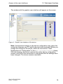
The window with the graphic user interface will appear on the screen.
Figure 4: Graphic user interface of the device
Note: Unintentional changes to the device configuration may cause the
connection between your PC and the device to be terminated. Before you
change the settings in the device, switch on the function "Undo
Modifications of Configuration" in the Basic Settings:Load/Save dialog.
With this function, the device restores the active device configuration
saved in the NVM if the connection is interrupted after the settings have
been changed. The device remains reachable.
RM GUI EAGLE20/30
Release 1.0 09/2012
19
Access to the user interfaces
1.3 Authentication List
1.3 Authentication List
Authentication lists specify one or more authentication methods to validate
access. Using the Security:Authentication List dialog you also manage
the authentication application.
1.3.1
Authentication method
There are various methods with which the device authenticates a user.
Configuring several user verification policies allows you to select every
method of authentication. If a user is unable to authenticate with the first
policy then the device uses the next policy for authentication. The device
attempts authentication using every configured possibility. Possible methods
are:
local: Locally configured user accounts are used for the authentication.
radius: A RADIUS server is used for the authentication.
1.3.2
Access Applications
The following access applications are available for accessing the device.
Assign connection applications to 1 authentication list at a time.
Console (V.24 connection)
SSH
Web Interface
20
RM GUI EAGLE20/30
Release 1.0 09/2012
Access to the user interfaces
1.4 User Management
1.4 User Management
Management access (system login) to the device, whether locally through
the V.24 port or remotely through the network, is password-protected using
a unique user ID and password combination dedicated to a specific user.
1.4.1
Privilege Levels
To allow for granular access control, a hierarchical, role-based user model is
utilized. Users at specific levels are granted use of commands at the same
or lower levels. The same privilege levels are applicable for every
management interface, i.e. CLI, Web Interface and SNMPv3. Three privilege
levels are available:
Administrator
Operator
Guest
the unauthorized privilege level is available for preparation of user
authorization or to temporarily disable a user account. The user is not
allowed access to the device at this privilege level.
Administrator
A user with this privilege level is authorized to manage local user
accounts. With these rights you can administrate this device and using the
following functions you can:
Add, change or delete local user accounts
Activate, deactivate or unlock local user accounts
Change user passwords
Configure password management
RM GUI EAGLE20/30
Release 1.0 09/2012
21
Access to the user interfaces
1.4 User Management
Set or change the system time
Load files to the device, e.g. device configurations, certificates or
software images
Reset settings to state on delivery
Reset security settings to state on delivery
Configure the RADIUS server and authentication lists
Use CLI scripts
Switch CLI logging and SNMP logging on and off
Activate and deactivate external memories
Activate and deactivate the system monitor
Activate and deactivate services for management access (e.g. SNMP)
Configure access restrictions to the user interface or the CLI on the
basis of IP addresses
Operator
A user with the privilege level operator has configuration access. This
excludes the the management functions described above. Furthermore,
the features you are authorized access to with this privilege level include:
Uploading files from the device to a host
Guest
The guest privilege level is a read-only account. At this level you are
authorized to view the status of the device.
22
RM GUI EAGLE20/30
Release 1.0 09/2012
Access to the user interfaces
1.4.2
1.4 User Management
Establishing new user accounts
Open the Security:User Management dialog.
Click the "Create" button to open new user account dialog.
In the "New Entry" frame, you enter the privilege level in the "Access
Role" field:
unauthorized - access is prohibited.
guest - access to observe status of device.
operator - limited management access to configure non-security relevant
features.
administrator - administration access
To maintain a high level of password security it is recommended that you place a
checkmark in the "Policy Check" checkbox.
enable
Switch to the privileged EXEC mode.
configure
Switch to the Configuration mode.
users add <user>
To add new user account.
users access-role <user>
Specify snmpv3 access role for a user as
operator
operator.
users password <user>
Through this dialog the administrator is able to
change the password of the new account.
users enable <user>
To activate user account.
show users
To confirm that the new user account has been
established with proper attributes.
Note: Enter a password when you create a user in the CLI. Without entering
a password for a new user, ***** appears in the "Password" column of the
web interface. Change this pseudo password so that the user has access to
the device.
RM GUI EAGLE20/30
Release 1.0 09/2012
23
Access to the user interfaces
1.4.3
1.4 User Management
Disabling user accounts
User accounts can be blocked by inserting a checkmark in the "User
locked" checkbox. Only a user with an administrator privilege
level has the authority to change this setting.
The unauthorized access role will also deny a user access to the
device. This feature is helpful in that you are able to maintain the
account information for future reactivation.
To permanently delete a user account, highlight the user to be
deleted then click "Delete".
enable
configure
users disable <user>
users access-role <user>
unauthorized
users delete <user>
show users
1.4.4
Switch to the privileged EXEC mode.
Switch to the Configuration mode.
To disable user account.
This command will change the access role of a
user to unauthorized, keeping the account
information in the buffer memory.
To permanently delete a user account.
To confirm that the new user account has been
established with proper attributes.
Passwords for Web access
Description of Password for Web Access
The passwords for local users follow a set of rules. Maintain these rules
when creating each password. You use these rules to establish the
strength of the password in the Security:User Management dialog,
"Password Policy" frame.
24
RM GUI EAGLE20/30
Release 1.0 09/2012
Access to the user interfaces
1.4 User Management
Changing the password for Web access
If you have an user account without administrative access, you will have
restricted write access to the device.
Note: Use between 5 and 32 characters for the password, since the
device does not accept shorter passwords.
Open the Security:User Management dialog.
To enter a new password double click on the password field located
in the "Password" column.
In addition, specify password attributes in the "Password Policy"
frame. When entering a new password a message will appear if the
"Policy Check" option has been activated and the attribute
conditions are not met.
You save the new password by clicking "Set".
enable
configure
users name <name> password
show users
Switch to the privileged EXEC mode.
Switch to the Configuration mode.
Through this dialog the user is able to change the
password.
To confirm that the new user account has been
established with proper attributes.
Passwords appear as ***** after saving. Therefore, document
password changes before saving. You cannot access the device without
a valid password.
RM GUI EAGLE20/30
Release 1.0 09/2012
25
Access to the user interfaces
1.5 RADIUS Server
1.5 RADIUS Server
Managing and determining the validity and privileges of users in a large
network can be significantly simplified and more secure by making use of a
single database of accessible information as provided by a RADIUS (Remote
Authentication Dial In User Service) server. The database within the RADIUS
server stores information about clients, users, passwords and access
privilege levels or roles, inlcuding the use of a shared secret.
26
RM GUI EAGLE20/30
Release 1.0 09/2012
Access to the user interfaces
1.5.1
1.5 RADIUS Server
Authentication Server
To validate users and terminals the device sends a request to a primary
authentication server. If no response is received from the primary server the
device sends a request to the secondary server if one has been configured.
The device attempts to send a request to the active servers until it receives
a response. Up to 8 Authentication servers can be configured.
Open the Security:RADIUS:Authentication Server dialog.
Click on "Create" to open the dialog window for entering the IP
address of a RADIUS server.
Confirm the entry of the IP address with "OK". Now you have created
a new line in the table for this RADIUS server.
In the "Secret" column you enter the character string which you get
as a key from the administrator of your RADIUS server.
With "Primary Server" you name this server as the first server which
the device should contact for port authentication queries. If this
server is not available, the device contacts the next server in the
table.
By clicking on "Delete" you delete the selected lines from the table.
enable
configure
show radius auth servers
radius server auth add 1 ip
10.0.1.153 name FIRSTRADIUS-svr
radius sever auth modify 1
secret
show radius auth servers
RM GUI EAGLE20/30
Release 1.0 09/2012
Switch to the privileged EXEC mode.
Switch to the Configuration mode.
Display the configured RADIUS Authentication
servers. Select the next available index.
Create a RADIUS primary authentication server
with the ip address of 10.0.1.153.
Enter the shared secret password received from
the server‘s administrator.
Display the configured RADIUS Authentication
servers.
27
Access to the user interfaces
28
1.5 RADIUS Server
RM GUI EAGLE20/30
Release 1.0 09/2012
Entering the IP Parameters
2 Entering the IP Parameters
When you install the device for the first time enter the IP parameters.
The device provides the following options for entering the IP parameters
during the first installation:
Entry using the Command Line Interface (CLI).
You choose this “out of band” method if
you preconfigure your device outside its operating environment, or
you need to restore network access (“in-band”) to the device
(see page 37 “Entering IP parameters via CLI”).
Entry using the HiDiscovery protocol.
You choose this “in-band” method if the device is already installed in the
network or if you have another Ethernet connection between your PC and
the device
(see page 40 “Entering the IP Parameters via HiDiscovery”).
Configuration via the Web-based interface.
If the device already has an IP address and can be reached via the
network, then the Web-based interface provides you with another option
for configuring the IP parameters.
RM GUI EAGLE20/30
Release 1.0 09/2012
29
Entering the IP Parameters
2.1 IP Parameter Basics
2.1 IP Parameter Basics
2.1.1
IP Address (Version 4)
The IP addresses consist of 4 bytes. These 4 bytes are written in decimal
notation, separated by a decimal point.
Since 1992, five classes of IP address have been defined in the RFC 1340.
Class
A
B
C
D
E
Table 1:
Network
address
1 byte
2 bytes
3 bytes
Host address
Address range
3 bytes
2 bytes
1 byte
0.0.0.0 to 127.255.255.255
128.0.0.0 to 191.255.255.255
192.0.0.0 to 223.255.255.255
224.0.0.0 to 239.255.255.255
240.0.0.0 to 255.255.255.255
IP address classes
The network address is the fixed part of the IP address. The worldwide
leading regulatory board for assigning network addresses is the IANA
(Internet Assigned Numbers Authority). If you require an IP address block,
contact your Internet service provider. Internet service providers should
contact their local higher-level organization:
APNIC (Asia Pacific Network Information Center) - Asia/Pacific Region
ARIN (American Registry for Internet Numbers) - Americas and SubSahara Africa
LACNIC (Regional Latin-American and Caribbean IP Address Registry) –
Latin America and some Caribbean Islands
RIPE NCC (Réseaux IP Européens) - Europe and Surrounding Regions
30
RM GUI EAGLE20/30
Release 1.0 09/2012
Entering the IP Parameters
0
Net ID - 7 bits
2.1 IP Parameter Basics
Host ID - 24 bits
Net ID - 14 bits
I
0
I
I
0
I
I
I
0
Multicast Group ID - 28 bits
Class D
I
I
I
I
reserved for future use - 28 b its
Class E
Net ID - 21 bits
Host ID - 16 bits
Class A
Host ID - 8 bit s
Class B
Class C
Figure 5: Bit representation of the IP address
All IP addresses belong to class A when their first bit is a zero, i.e. the first
decimal number is less than 128.
The IP address belongs to class B if the first bit is a one and the second bit
is a zero, i.e. the first decimal number is between 128 and 191.
The IP address belongs to class C if the first two bits are a one, i.e. the first
decimal number is higher than 191.
Assigning the host address (host ID) is the responsibility of the network
operator. He alone is responsible for the uniqueness of the IP addresses he
assigns.
RM GUI EAGLE20/30
Release 1.0 09/2012
31
Entering the IP Parameters
2.1.2
2.1 IP Parameter Basics
Netmask
Routers and gateways subdivide large networks into subnetworks. The
netmask assigns the IP addresses of the individual devices to a particular
subnetwork.
The division into subnetworks with the aid of the netmask is performed in
much the same way as the division of the network addresses (net id) into
classes A to C.
The bits of the host address (host id) that represent the mask are set to one.
The remaining bits of the host address in the netmask are set to zero (see
the following examples).
Example of a netmask:
Decimal notation
255.255.192.0
Binary notation
11111111.11111111.11000000.00000000
Subnetwork mask bits
Class B
Example of IP addresses with subnetwork assignment when the above
subnet mask is applied:
32
RM GUI EAGLE20/30
Release 1.0 09/2012
Entering the IP Parameters
2.1 IP Parameter Basics
Decimal notation
129.218.65.17
128 < 129 191 › Class B
Binary notation
10000001.11011010.01000001.00010001
Subnetwork 1
Network address
Decimal notation
129.218.129.17
128 < 129 191 › Class B
Binary notation
10000001.11011010.10000001.00010001
Subnetwork 2
Network address
RM GUI EAGLE20/30
Release 1.0 09/2012
33
Entering the IP Parameters
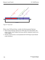
2.1 IP Parameter Basics
Example of how the network mask is used
In a large network it is possible that gateways and routers separate the
management agent from its management station. How does addressing
work in such a case?
Romeo
Juliet
Lorenzo
LAN 1
LAN 2
Figure 6: Management agent that is separated from its management station by a
router
The management station "Romeo" wants to send data to the
management agent "Juliet". Romeo knows Juliet's IP address and also
knows that the router "Lorenzo" knows the way to Juliet.
Romeo therefore puts his message in an envelope and writes Juliet's IP
address as the destination address. For the source address he writes his
own IP address on the envelope.
Romeo then places this envelope in a second one with Lorenzo's MAC
address as the destination and his own MAC address as the source. This
process is comparable to going from layer 3 to layer 2 of the ISO/OSI base
reference model.
Finally, Romeo puts the entire data packet into the mailbox. This is
comparable to going from layer 2 to layer 1, i.e. to sending the data packet
over the Ethernet.
34
RM GUI EAGLE20/30
Release 1.0 09/2012
Entering the IP Parameters
2.1 IP Parameter Basics
Lorenzo receives the letter and removes the outer envelope. From the
inner envelope he recognizes that the letter is meant for Juliet. He places
the inner envelope in a new outer envelope and searches his address list
(the ARP table) for Juliet's MAC address. He writes her MAC address on
the outer envelope as the destination address and his own MAC address
as the source address. He then places the entire data packet in the mail
box.
Juliet receives the letter and removes the outer envelope. She finds the
inner envelope with Romeo's IP address. Opening the inner envelope and
reading its contents corresponds to transferring the message to the higher
protocol layers of the SO/OSI layer model.
Juliet would now like to send a reply to Romeo. She places her reply in an
envelope with Romeo's IP address as destination and her own IP address
as source. But where is she to send the answer? For she did not receive
Romeo's MAC address. It was lost when Lorenzo replaced the outer
envelope.
In the MIB, Juliet finds Lorenzo listed under the variable
hmNetGatewayIPAddr as a means of communicating with Romeo. She
therefore puts the envelope with the IP addresses in a further envelope
with Lorenzo's MAC destination address.
The letter now travels back to Romeo via Lorenzo, the same way the first
letter traveled from Romeo to Juliet.
RM GUI EAGLE20/30
Release 1.0 09/2012
35
Entering the IP Parameters
2.1.3
2.1 IP Parameter Basics
Classless Inter-Domain Routing
Class C with a maximum of 254 addresses was too small, and class B with
a maximum of 65,534 addresses was too large for most users. This resulted
in ineffective usage of the class B addresses available.
Class D contains reserved multicast addresses. Class E is reserved for
experimental purposes. A gateway not participating in these experiments
ignores datagrams with these destination addresses.
Since 1993, RFC 1519 has been using Classless Inter-Domain Routing
(CIDR) to provide a solution. CIDR overcomes these class boundaries and
supports classless address ranges.
With CIDR, you enter the number of bits that designate the IP address range.
You represent the IP address range in binary form and count the mask bits
that designate the netmask. The netmask indicates the number of bits that
are identical to the network part for the IP addresses in a given address
range. Example:
IP address, decimal
Network mask,
decimal
IP address, binary
149.218.112.1
149.218.112.127
255.255.255.128
10010101 11011010 01110000 00000001
10010101 11011010 01110000 01111111
25 mask bits
CIDR notation: 149.218.112.0/25
Mask bits
The combination of a number of class C address ranges is known as
“supernetting”. This enables you to subdivide class B address ranges to a
very fine degree.
36
RM GUI EAGLE20/30
Release 1.0 09/2012
Entering the IP Parameters
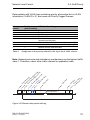
2.2 Entering IP parameters via CLI
2.2 Entering IP parameters via
CLI
Entering IP addresses
Connect the PC with terminal
program started to the RJ11 socket
Command Line Interface
starts after key press
Log in and change to the
Privileged EXEC Mode
Enter and save IP parameters
End of entering IP addresses
Figure 7: Flow chart for entering IP addresses
RM GUI EAGLE20/30
Release 1.0 09/2012
37
Entering the IP Parameters
2.2 Entering IP parameters via CLI
Note: If there is no terminal or PC with terminal emulation available in the
vicinity of the installation location, you can configure the device at your own
workstation, then take it to its final installation location.
Set up a connection to the device (see on page 14 “Command Line
Interface”).
The start screen appears.
NOTE: Enter '?' for Command Help. Command help displays all options
that are valid for the 'normal' and 'no' command forms. For
the syntax of a particular command form, please consult the
documentation.
(EAGLE) >
Enter the IP parameters.
Local IP address
On delivery, the device has the local IP address 0.0.0.0.
Netmask
If your network has been divided up into subnetworks, and if these are
identified with a netmask, then the netmask is to be entered here.
The default setting of the netmask is 0.0.0.0.
IP address of the gateway
This entry is only required if the device and the management station or
TFTP server are located in different subnetworks (see page 34
“Example of how the network mask is used”).
Enter the IP address of the gateway between the subnetwork with the
device and the path to the management station.
The default setting of the IP address is 0.0.0.0.
Save the configuration entered using
copy config running-config nvm.
38
RM GUI EAGLE20/30
Release 1.0 09/2012
Entering the IP Parameters
enable
network protocol none
network parms 10.0.1.23
255.255.255.0
copy config running-config
nvm
2.2 Entering IP parameters via CLI
Switch to the privileged EXEC mode.
Deactivate DHCP.
Assign the device the IP address 10.0.1.23 and
the netmask 255.255.255.0. You have the option
of also assigning a gateway address.
Save the current configuration to the non-volatile
memory.
After entering the IP parameters, you can easily configure the device via the
Web-based interface (see the “GUI” (Graphical User Interface / Web-based
Interface) reference manual).
RM GUI EAGLE20/30
Release 1.0 09/2012
39
Entering the IP Parameters
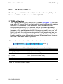
2.3 Entering the IP Parameters via
HiDiscovery
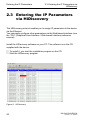
2.3 Entering the IP Parameters
via HiDiscovery
The HiDiscovery protocol enables you to assign IP parameters to the device
via the Ethernet.
You can easily configure other parameters via the Web-based interface (see
the “GUI” (Graphical User Interface / Web-based Interface) reference
manual).
Install the HiDiscovery software on your PC. The software is on the CD
supplied with the device.
To install it, you start the installation program on the CD.
Start the HiDiscovery program.
Figure 8: HiDiscovery
40
RM GUI EAGLE20/30
Release 1.0 09/2012
Entering the IP Parameters
2.3 Entering the IP Parameters via
HiDiscovery
When HiDiscovery is started, HiDiscovery automatically searches the
network for those devices which support the HiDiscovery protocol.
HiDiscovery uses the first network interface found for the PC. If your
computer has several network cards, you can select the one you desire in the
HiDiscovery toolbar.
HiDiscovery displays a line for every device that reacts to the HiDiscovery
protocol.
HiDiscovery enables you to identify the devices displayed.
Select a device line.
Click on the signal symbol in the tool bar to set the LEDs for the selected
device flashing. To switch off the flashing, click on the symbol again.
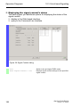
By double-clicking a line, you open a window in which you can enter the
device name and the IP parameters.
Figure 9: HiDiscovery – assigning IP parameters
Note: When the IP address is entered, the device copies the local
configuration settings (see on page 45 “Configuration Management”).
Note: For security reasons, switch off the HiDiscovery function for the device
in the Web-based interface, after you have assigned the IP parameters to the
device (see on page 43 “Web-based IP Configuration”).
RM GUI EAGLE20/30
Release 1.0 09/2012
41
Entering the IP Parameters
2.3 Entering the IP Parameters via
HiDiscovery
Note: Save the settings so that you will still have the entries after a restart
(see on page 45 “Configuration Management”).
42
RM GUI EAGLE20/30
Release 1.0 09/2012
Entering the IP Parameters
2.4 Web-based IP Configuration
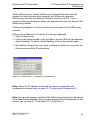
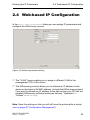
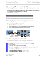
2.4 Web-based IP Configuration
In the Basic Settings:Network dialog you can assign IP parameters and
configure the HiDiscovery access.
Figure 10: Network parameters dialog
The "VLAN" frame enables you to assign a different VLAN to the
management CPU of the device.
The HiDiscovery protocol allows you to allocate an IP address to the
device on the basis of its MAC address. Activate the HiDiscovery protocol
if you want to allocate an IP address to the device from your PC with the
supplied HiDiscovery software (setting on delivery: "Operation"on,
"Access"read-write).
Note: Save the settings so that you will still have the entries after a restart
(see on page 45 “Configuration Management”).
RM GUI EAGLE20/30
Release 1.0 09/2012
43
Entering the IP Parameters
44
2.4 Web-based IP Configuration
RM GUI EAGLE20/30
Release 1.0 09/2012
Configuration Management
3 Configuration Management
The device saves settings such as the IP parameters and the port
configuration in the temporary memory. These settings are lost when you
switch off or reboot the device.
The device allows you to do the following:
Load settings from a non-volatile memory into the temporary memory
Save settings from the temporary memory in a non-volatile memory
If you change the current configuration (e.g. disable a port), after updating,
the tool bar of the graphical user interface displays the symbol
. After
saving the configuration and updating the tool bar, the symbol disappears.
RM GUI EAGLE20/30
Release 1.0 09/2012
45
Configuration Management
3.1 Loading settings
3.1 Loading settings
Note: Details of times required for a reboot:
The time required for a cold start is the time taken by the device from the
moment power is switched on until it is fully connected and its
Management-CPU is fully accessible.
Depending on the device type and the extent of the configuration settings,
a cold start takes at least about 10 seconds.
Extensive configuration settings will increase the time required for a
reboot, especially if they contain a high number of VLANs. In extreme
cases, a reboot can take up to about 200 seconds.
During operation, the device allows you to load settings from the following
sources:
the local non-volatile memory
a file in the connected network (setting on delivery)
the firmware (restoration of the configuration on delivery).
Note: When loading a configuration, hold off any accesses to the device until
it has loaded the configuration file and applied the new configuration settings.
Depending on the device type and the extent of the configuration settings,
this process can take between 10 and 200 seconds.
Note: Loading a configuration deactivates the ports while the configuration is
being set up. Afterwards, the Switch sets the port status according to the new
configuration.
46
RM GUI EAGLE20/30
Release 1.0 09/2012
Configuration Management
3.1.1
3.1 Loading settings
Loading from the local non-volatile memory
When loading the configuration data locally, the device loads the
configuration data from the local non-volatile memory.
Open the Basic Settings:Load/Save dialog.
Highlight the NVM line to be loaded.
Click "Activate" to activate the configuration.
Click "Load" to load the configuration.
enable
copy config nvm
running-config
3.1.2
Switch to the privileged EXEC mode.
The device loads the configuration data from the
local non-volatile memory.
Loading from a file
The device allows you to load the configuration data from a file in the
connected network.
Select the "Storage Type" in the "Destination" frame:
nvm for non-volatile memory
ram for volatile memory.
Enter a Profile "Name" to appear in the list.
Click "OK".
RM GUI EAGLE20/30
Release 1.0 09/2012
47
Configuration Management
3.1.3
3.1 Loading settings
Resetting the configuration to the state on
delivery
The device enables you to:
reset the current configuration to the state on delivery.
reset the device to the state on delivery. After the next restart, the IP
address is also in the state on delivery.
Click on the blue arrow in the Basic Settings:Load/Savedialog and
then click "Back to factory defaults...".
enable
clear factory
Switch to the privileged EXEC mode.
The device clears the configurations.
Resetting the device using System Monitor 1
The device is reset to the factory setting using option 4 of System
Monitor 1.
Enter the CLI global command reboot. As the device is rebooting
press 1 to enter the System Monitor.
Enter 4 (Manage configurations).
Enter 1 (Boot default configurations).
48
RM GUI EAGLE20/30
Release 1.0 09/2012
Configuration Management
3.2 Saving settings
3.2 Saving settings
When you actuate the "Save" button in Basic Settings:Load/Save dialog,
the device will save the current configurations in the following places:
on the device
On the external memory
3.2.1
Saving locally
The device allows you to save the current configuration data in the local nonvolatile memory.
Open the Basic Settings:Load/Save dialog.
Click on "Save".
The device stores the current configuration data in the local nonvolatile memory.
enable
copy config running-config
nvm
RM GUI EAGLE20/30
Release 1.0 09/2012
Switch to the privileged EXEC mode.
The device stores the current configuration data
in the local non-volatile memory.
49
Configuration Management
3.2.2
3.2 Saving settings
Saving on a PC
The device allows you to save the current configuration data in XML format
on your PC.
Highlight the configuration to be saved in the Basic Settings:Load/
Save dialog
Actuate the blue down arrow to display more file management
options.
Click on "Export...".
Enter the URL for the location where the file is to be saved. The
device allows you to enter the URL manually. Use the "..." button to
assist you in finding the location where the file is to be stored.
Click on "OK" to save the file.
50
RM GUI EAGLE20/30
Release 1.0 09/2012
Loading Software Updates
4 Loading Software Updates
Hirschmann is continually working to improve and develop our software. You
should regularly check whether there is a new version of the software that
provides you with additional benefits. You will find software information and
downloads on the product pages of the Hirschmann website.
Checking the installed Software Release
Open the Basic Settings:Software dialog.
This dialog indicates the Release Number of the software installed
in the device.
enable
show system info
Switch to the privileged EXEC mode.
Show system information.
Loading the software
The device gives you the following options for loading the software:
via a file selection dialog from your PC.
Note: The existing configuration of the device is still there after the new
software is installed.
RM GUI EAGLE20/30
Release 1.0 09/2012
51
Loading Software Updates
4.1 Loading the Software via File
Selection
4.1 Loading the Software via File
Selection
For a software update via a file selection window, the device software must
be on a data carrier that you can access from your PC.
Open the Basic Settings:Software dialog.
Click on ".." in the "Software Update" frame.
In the "Open" dialog select the file with the suffix *.bin, e.g.
HiSecOS-EAGLE-01000.bin.
Click on "Open".
Click on "Update" to transfer the software to the device.
When the file is completely transferred, the device starts updating
the device software. If the update was successful, the device
displays the message "Successfully firmware update on EAGLE20/
30".
Restart the device.
After restarting the device works with the updated software.
52
RM GUI EAGLE20/30
Release 1.0 09/2012
Loading Software Updates
4.2 Software update via SFTP/SCP
4.2 Software update via SFTP/
SCP
The device offers the possibility to upload the new software from your PC via
SFTP or SCP onto your device. Therefore you need an SFTP or SCP client,
e. g. WinSCP. In order to transfer the software, you perform the following
steps:
On your PC, open an SFTP or SCP client, e.g. WinSCP.
Use the SFTP or SCP client to open a connection to the device.
Transfer the file with the ending *.bin, e.g. HiSecOS-EAGLE-01000.bin,
to the /upload/firmware directory on the device.
When the file is completely transferred, the device starts updating the
device software. If the update was successful, the device creates an ok
file in directory /upload/firmware and deletes the file with the ending
*.bin.
Restart the device.
After restarting the device works with the updated software.
RM GUI EAGLE20/30
Release 1.0 09/2012
53
Loading Software Updates
54
4.2 Software update via SFTP/SCP
RM GUI EAGLE20/30
Release 1.0 09/2012
Configuring the Ports
5 Configuring the Ports
The following port configuration functions are available.
Switching the port on and off,
Selecting the operating mode,
Displaying detected loss of connection
Switching the port on and off
In the state on delivery, every port is switched on. For a higher level of
access security, switch off the ports for which you are not making any
connection.
Open the Basic Settings:Port Configuration dialog.
In the "Port on" column, activate the ports that are connected to
another device.
Selecting the operating mode
In the state on delivery, the ports are set to "Automatic Configuration"
operating mode.
Note: The active automatic configuration has priority over the manual
configuration.
Open the Basic Settings:Port Configuration dialog.
If the device connected to this port requires a fixed setting:
Select the operating mode (transmission rate, duplex mode) in the "Manual
Configuration" column.
Deactivate the checkbox in the "Automatic Configuration" column.
RM GUI EAGLE20/30
Release 1.0 09/2012
55
Configuring the Ports
56
RM GUI EAGLE20/30
Release 1.0 09/2012
Assistance in the Protection from
Unauthorized Access
6 Assistance in the Protection
from Unauthorized Access
The device provides the following functions to help prevent unauthorised
accesses.
Password for SNMP access
Switching off access to the device via the following services:
– SSH
– HTTPS
– SNMP
Restricted IP Access
HiDiscovery-Function can be switched off
RM GUI EAGLE20/30
Release 1.0 09/2012
57
Assistance in the Protection from
Unauthorized Access
6.1 Handling unauthorised accesses
6.1 Handling unauthorised
accesses
If you want to maximize the protection of the device against unauthorized
access in just a few steps, you can perform the following steps on the device
as required:
Deactivate SNMPv1 and SNMPv2 (per default deactivated) and select a
password for SNMPv3 access other than the standard password.
Deactivate SSH access (see on page 61 “Access to the device”).
Deactivate HiDiscovery access.
Note: Retain at least one option to access the device. Connecting to the
device via V.24 serial access is possible, since it cannot be deactivated.
58
RM GUI EAGLE20/30
Release 1.0 09/2012
Assistance in the Protection from
Unauthorized Access
6.2 SNMPv1/v2 Community
6.2 SNMPv1/v2 Community
6.2.1
Description of SNMPv1/v2
A network management station communicates with the device via the Simple
Network Management Protocol (SNMP).
Every SNMP packet contains the IP address of the sending computer and the
Community Name with which the sender of the packet wants to access the
device MIB.
The device receives the SNMP packet and compares the Community Name
of the sending computer with the entries in the device‘s MIB.
If the name has the appropriate access level then the device will allow access
for the designated permission level.
In the delivery state, the device is accessible via the password public
(Read) and private (Read and Write) from every computer.
To help protect your device from unwanted access:
First define new names with which you have viewing (Read) and
administrative (Read and Write) access to the device from your computer.
Treat these names as confidential, because everyone who knows the
name can access the device MIB.
Note: SNMPv1 and SNMPv2 are potentially unsecure, because the device
sends the community name as plain text. For this reason, SNMPv1 and
SNMPv2 are per default deactivated. Turn on this function when other
possibilities are unavailable and you are aware of the consequences.
RM GUI EAGLE20/30
Release 1.0 09/2012
59
Assistance in the Protection from
Unauthorized Access
6.2.2
6.2 SNMPv1/v2 Community
Entering the SNMPv1/v2 name
Open the Security:Management Access:SNMPv1/v2 Community
dialog.
This dialog gives you the option of changing the read and write
names for the SNMPv1/v2 Community.
In the "Name" frame, specify the desired name for reading access
and for writing access. Users with reading access should neither
know nor be able to guess the name for writing access.
To enter a new read name double click on the name located in the
"Community":"Read":"Name" field.
Enter the new read name in the "Name" field.
To enter a new read/write name double click on the "Name" field.
Enter the new read/write name in the "Name" field.
You save the new name by actuating "Set" and then "Reload".
Open the Security:Management Access:Server dialog.
In the "Configuration" frame, select the "SNMPv1 enabled" or
"SNMPv2 enabled" checkboxes.
The user accounts set up in the device use the same passwords in the webbased interface, in the Command Line Interface (CLI) and for SNMPv3.
60
RM GUI EAGLE20/30
Release 1.0 09/2012
Assistance in the Protection from
Unauthorized Access
6.3 Access to the device
6.3 Access to the device
Switching off access to the device via the following services:
SSH
HTTPS
SNMP
6.3.1
Description of SSH Access
The device's SSH server allows you to configure the device using the
Command Line Interface (in-band). You can deactivate the SSH server to
help prevent SSH access to the device.
The server is activated in its state on delivery.
After the SSH server has been deactivated, you will no longer be able to
access the device via a new SSH connection. If an SSH connection already
exists, it is retained.
In the Security:Management Access:Server dialog, open the "SSH"
tab page.
In the "Operation" frame select the Off radio button to disable the
server, refusing SSH access.
enable
configure
ssh server
no ssh server
Switch to the privileged EXEC mode.
Switch to the Configuration mode.
Enable SSH function.
Disable SSH function.
Note: If a host key is not present, the device generates a DSA and RSA key
at startup. After key generation activate the server. The server is available
after generating at least 1 key.
RM GUI EAGLE20/30
Release 1.0 09/2012
61
Assistance in the Protection from
Unauthorized Access
6.3 Access to the device
Note: The Command Line Interface (out-of-band) and the
Security:Management Access:Server dialog, "SSH" register, in the Webbased interface allows you to reactivate the SSH server.
6.3.2
Description of HTTPS Access
The web server uses HTTPS to load a Java applet for the web-based
interface onto your computer.
The server is activated in its state on delivery.
After deactivating the HTTPS server, you will no longer be able to access the
device via a new HTTPS connection. Existing HTTPS connections remain.
In the Security:Management Access:Server dialog, open the
"HTTPS" tab page.
In the "Operation" frame select the Off radio button to disable the
server, refusing HTTPS access.
enable
configure
https server
no https server
Switch to the privileged EXEC mode.
Switch to the Configuration mode.
Enable HTTPS function.
Disable HTTPS function.
Note: In order to activate the HTTPS server, a certificate must be present. If
a certificate is not present at startup the device generates it.
Note: The Command Line Interface (out-of-band) allows you to reactivate
the HTTPS server.
62
RM GUI EAGLE20/30
Release 1.0 09/2012
Assistance in the Protection from
Unauthorized Access
6.4 IP Access Restriction
6.4 IP Access Restriction
The device allows you to differentiate the management access based on IP
address ranges, and to differentiate these based on management services.
With this option you have the ablity to granularly set management access
rights.
If you only want the device, which is located in a production plant for
example, to be managed from the network of the IT department via the Web
interface but also want the administrator to be able to access it remotely via
SSH, you can achieve this with the "IP Access Restriction" function.
Configure this function using the web-based interface or the CLI. The webbased interface provides you with an easy configuration option. However, to
verify that you maintain access to the device use the CLI option with a serial
V.24 connection.
In the following example, the IT network has the address range 192.168.1.0/
24 and the remote access is from a mobile phone network with the IP
address range 109.237.176.0 - 109.237.176.255.
The device is always available for SSH access and the SSH client application
already knows the fingerprint of the host key on the device.
See “Preparing access via SSH” on page 170.
Parameter
IT network
Network address
Netmask
Desired management access
192.168.1.0
24
https, snmp
Table 2:
Mobil phone
network
109.237.176.0
24
ssh
Example parameters for the restricted management access
Open the Security:Management Access:IP Access Restriction
dialog.
Leave the existing entry unchanged and use the "Create" button to
create a new entry for the IT network.
Enter the IP Address Range192.168.1.0/24.
Deactivate the SSH service. Leave the HTTPS and SNMP services
on.
RM GUI EAGLE20/30
Release 1.0 09/2012
63
Assistance in the Protection from
Unauthorized Access
6.4 IP Access Restriction
Use the "Create" button to create a new entry for the mobile phone
network.
Enter the IP Address Range 109.237.176.0/24.
Deactivate the HTTPS and SNMP services and leave SSH
activated.
Verify that you have CLI access to the device via V.24.
Deactivate the preset entry. There are no restrictions set with this
entry and would cause your subsequent entries to have no effect.
Enable the desired port with a check in the "Active" checkbox.
Click on "Write" to temporarily save the data.
If your current management station is also located in the IT network,
you continue to have access to the Web-based interface. Otherwise
the device ignores operations via the Web-based interface, and it
also rejects a restart of the Web-based interface.
Check whether you can access the device from the IT network via
https and snmp: Open the Web-based interface of the device in a
browser, login on the start screen, and check whether you can read
data (as user “user”) or read and write data (as user “admin”).
Check whether the device rejects connections via ssh.
Check whether you can access the device from the mobile phone
network via ssh: Open an SSH client, make a connection to the
device, login, and check whether you can read or read and write
data.
Check whether the device rejects connections via https and snmp.
When you have successfully completed both tests, save the settings
in the non-volatile memory. Otherwise check your configuration. If
the device rejects access with the Web-based interface, use the CLI
of the device to initially deactivate the function via V.24.
enable
show network management
access global
show network management
access rules
network management access add
2
network mangement access
modify 2 ip 192.168.1.24
network management access
modify 2 mask 24
network management access
modify 2 ssh disable
network management access add
3
64
Switch to the privileged EXEC mode.
Display the current function status.
Display the restricted management access rules.
Create an entry for the IT network. Number of
next available index- in the example, 2.
Set the IP address of the entry for the IT network.
Set the netmask of the entry for the IT network.
Deactivate SSH for the entry of the IT network.
Create an entry for the mobile phone network. In
the example, this is given the ID 3.
RM GUI EAGLE20/30
Release 1.0 09/2012
Assistance in the Protection from
Unauthorized Access
network management access
modify 3 ip 109.237.176.24
network management access
modify 3 mask 24
network management access
modify 3 snmp disable
no network management access
status 1
network management access status 2
network management access status 3
network management access
operation
show network management
access rules
copy config running-config
nvm
RM GUI EAGLE20/30
Release 1.0 09/2012
6.4 IP Access Restriction
Set the IP address of the entry for the mobile
phone network.
Set the netmask of the entry for the mobile phone
network.
Deactivate snmp for the entry of the mobile phone
network.
Deactivate the preset entry.
Activates the entry 2.
Activates the entry 3.
Enable operation for RMA.
Display the restricted management access rules.
The device stores the current configuration data
in the local non-volatile memory.
65
Assistance in the Protection from
Unauthorized Access
6.5 Access Control Lists
6.5 Access Control Lists
In this menu you can enter the settings for the Access Control Lists (ACLs).
The device uses access control lists to filter data packets or frames coming
in at individual or multiple ports or at VLANs. In the respective ACL, you
create rules that the device uses to carry out filtering. When such a rule
applies to a packet or a frame, the device applies the actions defined in the
rule to the packet or frame. Four possible actions are available here:
Allow ("permit")
Discard ("deny")
Redirect to a certain port (through the "Redirection Port" entry)
Mirror (through the "Mirror Port" entry)
You can filter incoming data according to the following criteria:
Source or destination address of a frame (MAC)
Source or destination address of a data packet (IPv4)
Type of the transmitting protocol (MAC/IPv4)
Source or destination port of a data packet (IPv4)
Service class of a frame (MAC)
Membership of a specific VLAN (MAC)
Classification according to DSCP (IPv4)
Classification according to ToS (IPv4)
The assignment of IP ACLs and MAC ACLs to ports and VLANs results in
four different types of ACLs:
IP ACLs for VLANs
IP ACLs for ports
MAC ACLs for VLANs
MAC ACLs for ports
Within an ACL type, the device processes the rules in order, with the index
of the respective role determining the corresponding order. You can thus
define the priority of a rule using the index or sequence number when you
assign an ACL to a port or VLAN. The following generally applies: the lower
the sequence number, the higher the priority. When processing the rules, the
device processes the rule with the higher priority first.
66
RM GUI EAGLE20/30
Release 1.0 09/2012
Assistance in the Protection from
Unauthorized Access
6.5 Access Control Lists
When several ACL types contain rules that apply to a data packet, the priority
of the ACL type decides which rule the device applies first. Note that the
priority of an ACL type is independent of the index or sequence number of a
rule. It is generally true that IP ACLs have a higher priority than MAC ACLs.
The device thus gives preference to IP ACLs over MAC ACLs.
You can create up to 128 MAC ACLs and up to 128 IP ACLs. Each ACL can
contain up to 239 rules, with the device allowing a maximum number of 956
rules regardless of the ACL type. This corresponds to four completely filled
ACLs with 239 rules each.
You can assign a maximum of 239 rules to a single port, irrespectively of the
ACL tpye used.
The assignment of ACLs to single ports corresponds to the maximum
number of ACLs you can create. This means you can simultaneously assign
a maximum of 128 MAC ACLs and 128 IP ACLs to a single port.
You can assign a maximum of 176 rules to a single VLAN, reguardless of the
ACL tpye used.
Assigning ACLs to VLANs is limited to 64 VLANs. This means you can
simultaneously assign the ACLs to a maximum of 64 VLANs.
Note: You can assign a single ACL to any number of ports or VLANs.
If you have assigned one or several ACLs to a port or VLAN, the device will
process the ACLs corresponding to their priority when traffic comes in on an
interface. If none of the rules contained in the ACLs match an incoming data
packet, the default “deny” rule will apply. As a result, the device will drop all
incoming data packets.
Keep in mind that the default “deny” rule is directly implemented in the
device. You cannot edit or change this rule.
RM GUI EAGLE20/30
Release 1.0 09/2012
67
Assistance in the Protection from
Unauthorized Access
6.5 Access Control Lists
The "Access Control Lists" menu contains the following dialogs:
IPv4 Name
IPv4 Rule
MAC Name
MAC Rule
Port Assignment
VLAN Assignment
In these dialogs you can designate the rules for the various ACL types,
configure them, and provide them with the required priorities. You also take
care of the assignment of the rules to certain ports or VLANs here.
6.5.1
IPv4 Name
This dialog allows you to create, name, activate and deactivate ACLs for
filtering of IPv4 data packets.
Proceed as follows to create and save a new IP ACL:
Click the "Create" button.
This will add a new entry to the table. The device will automatically
assign a sequential index number to the newly created entry.
Click on the "Name" field and enter a meaningful name. You are
allowed to enter 1 to 31 alphanumeric characters. The default name
is default.
Click the "Active" field of this entry to activate the IP ACL.
Click "Set" to transfer the IP ACL to the volatile memory of the
device.
To permanently save the changes, choose the active device
configuration in the Basic Settings:Load/Save dialog and click
"Save".
68
RM GUI EAGLE20/30
Release 1.0 09/2012
Assistance in the Protection from
Unauthorized Access
6.5 Access Control Lists
Actuate the "Reload" button if you want to update the table with values
edited outside of the web interface (e. g. via the CLI).
In order to remove an ACL entry from the list, select the entry and click
the "Remove" button.
6.5.2
IPv4 Rule
In this dialog you can configure the individual rules for IPv4 ACLs. The rules
created here only relate to IP data packets.
Proceed as follows to create and edit a new IPv4 rule:
Click the "Create" button. Select an ACL and assign an index
number to the rule that you want to configure. Keep in mind that the
index number determines the priority of the rule.
Confirm the current selection by clicking "OK". The device will add
this selection to the table.
For each rule created, edit the individual parameters in the table.
Click the "Active" field of an entry to activate the respective rule.
Click "Set" to transfer the rule to the volatile memory of the device.
To permanently save the changes, choose the active device
configuration in the Basic Settings:Load/Save dialog and click
"Save".
Note: You can use wildcards with the "Source IP Address" and "Destination
IP Address" parameters. If you enter, for example, 192.168.?.?, the
device will admit all addresses the first two octets of which start with
192.168..
RM GUI EAGLE20/30
Release 1.0 09/2012
69
Assistance in the Protection from
Unauthorized Access
6.5 Access Control Lists
Note: Editing the "Source TCP/UDP Port" and "Destination TCP/UDP Port"
parameters requires you to set either of the values tcp or udp in the
"Protocol" field beforehand.
Note: Configuring a port with the "Redirection Port" or "Mirror Port"
parameters requires you to set the "Action" parameter to permit
beforehand.
Click the "Reload" button in order to
update the table with changes to an existing ACL name previously
made in the "IPv4 Name" dialog;
update the table with values edited outside of the web interface (e. g.
via the CLI).
In order to remove a rule from the list, select the rule and click the
"Remove" button.
6.5.3
MAC Name
This dialog allows you to create, name, activate and deactivate ACLs for
filtering MAC frames.
Proceed as follows to create and save a new MAC ACL:
Click the "Create" button.
This will add a new entry to the table. The device will automatically
assign a sequential index number to the newly created entry.
Click on the "Name" field and enter a meaningful name. You are
allowed to enter 1 to 31 alphanumeric characters. The default name
is default.
70
RM GUI EAGLE20/30
Release 1.0 09/2012
Assistance in the Protection from
Unauthorized Access
6.5 Access Control Lists
Click the "Active" field of this entry to activate the MAC ACL.
Click "Set" to temporarily save the MAC ACL in the configuration.
To permanently save the changes, choose the active device
configuration in the Basic Settings:Load/Save dialog and click
"Save".
Actuate the "Reload" button if you want to update the table with values
edited outside of the web interface (e. g. via the CLI).
In order to remove an ACL entry from the list, select the entry and click
the "Remove" button.
6.5.4
MAC Rule
In this dialog you can configure the individual rules for MAC ACLs. The rules
created here only relate to MAC frames.
Proceed as follows to create and edit a new MAC rule:
Click the "Create" button. Select an ACL and assign an index
number to the rule that you want to configure. Keep in mind that the
index number determines the priority of the rule.
Confirm the current selection by clicking "OK". The device will add
this selection to the table.
For each rule created, edit the individual parameters in the table.
Click the "Active" field of an entry to activate the respective rule.
Click "Set" to transfer the rule to the volatile memory of the device.
To permanently save the changes, choose the active device
configuration in the Basic Settings:Load/Save dialog and click
"Save".
RM GUI EAGLE20/30
Release 1.0 09/2012
71
Assistance in the Protection from
Unauthorized Access
6.5 Access Control Lists
Note: You can use wildcards with the "Source MAC Address" and
"Destination MAC Address" parameters. Both parameters allow you to enter
address filters which, e. g., may have the form FF:??:??:??:??:?? or
??:??:??:??:00:01. Be sure to use capital letters here.
Note: Configuring a port with the "Redirection Port" or "Mirror Port"
parameters requires you to set the "Action" parameter to permit
beforehand.
Click the "Reload" button in order to
update the table with changes to an existing ACL name previously
made in the "MAC Name" dialog;
update the table with values edited outside of the web interface (e. g.
via the CLI).
In order to remove a rule from the list, select the rule and click the
"Remove" button.
72
RM GUI EAGLE20/30
Release 1.0 09/2012
Assistance in the Protection from
Unauthorized Access
6.5.5
6.5 Access Control Lists
Port Assignment
With this dialog you can assign the ACLs to specific ports.
Proceed as follows to edit an assignment:
Click the "Assign" button. Select the desired port and configure the
parameters "Sequence", "Direction" and "Rule Index". Be sure to set
the "Direction "parameter to inbound .
Confirm the current selection by clicking "OK". The device will add
this selection to the table.
Click "Set" to transfer the rule to the volatile memory of the device.
To permanently save the changes, choose the active device
configuration in the Basic Settings:Load/Save dialog and click
"Save".
Actuate the "Reload" button if you want to update the table with values
edited outside of the web interface (e. g. via the CLI).
In order to remove an ACL entry from the list, select the entry and click
the "Remove" button.
RM GUI EAGLE20/30
Release 1.0 09/2012
73
Assistance in the Protection from
Unauthorized Access
6.5.6
6.5 Access Control Lists
VLAN Assignment
This dialog allows you to assign the ACLS to individual VLANs.
Proceed as follows to edit an assignment:
Click the "Assign" button. Select the desired port and configure the
parameters "Sequence", "Direction" and "Rule Index". Be sure to set
the "Direction "parameter to inbound .
Confirm the current selection by clicking "OK". The device will add
this selection to the table.
Click "Set" to transfer the rule to the volatile memory of the device.
To permanently save the changes, choose the active device
configuration in the Basic Settings:Load/Save dialog and click
"Save".
Actuate the "Reload" button if you want to update the table with values
edited outside of the web interface (e. g. via the CLI).
In order to remove an ACL entry from the list, select the entry and click
the "Remove" button.
74
RM GUI EAGLE20/30
Release 1.0 09/2012
Assistance in the Protection from
Unauthorized Access
6.6 HiDiscovery Access
6.6 HiDiscovery Access
6.6.1
Description of the HiDiscovery Protocol
The HiDiscovery protocol allows you to allocate an IP address to the device
on the basis of its MAC address (see on page 40 “Entering the IP Parameters
via HiDiscovery”). HiDiscovery is a Layer 2 protocol.
Note: Restrict the HiDiscovery function for the device or disable it after you
have assigned the IP parameters to the device.
6.6.2
Enabling/disabling the HiDiscovery Function
Open the Basic Settings:Network dialog.
In the "HiDiscovery Protocol" frame, disable the HiDiscovery
function or restrict the access to readOnly.
enable
no network hidiscovery
operation
network hidiscovery mode
read-only
network hidiscovery mode
read-write
RM GUI EAGLE20/30
Release 1.0 09/2012
Switch to the privileged EXEC mode.
Disable the HiDiscovery function.
Enable HiDiscovery function with “read-only”
access
Enable HiDiscovery function with “read-write”
access
75
Assistance in the Protection from
Unauthorized Access
6.7 Session Timeouts
6.7 Session Timeouts
The following session timeouts are available on the device. Open the
Security:Management Access dialog.
6.7.1
CLI and Web session
Use the Security Management Access:Web dialog to configure how long a
Web Interface session remains open.
Using the Security:Management Access:CLI dialog you configure what
name appears in the CLI prompt. You also configure how long a CLI session
remains open.
Use the login banner to provide a message for device users.
In the Security:Management Access:CLI dialog, open the "Global"
tab page.
Enter the name that you want to appear for a prompt in the "Login
Prompt" field in the "Configuration" frame.
Enter how long a CLI session remains open in the
"V.24 Timeout [min]" field in the "Configuration" frame.
In the Security:Management Access:CLI dialog, open the "Login
Banner" tab page.
Enable this feature in the "Operation" frame.
Enter the text you want to appear on the device.
76
RM GUI EAGLE20/30
Release 1.0 09/2012
Assistance in the Protection from
Unauthorized Access
enable
cli prompt name
cli banner operation
cli banner text
6.7 Session Timeouts
Switch to the privileged EXEC mode.
Change the system prompt.
Enable or disable the CLI banner.
Edit the text to appear in the CLI login banner.
Note: The banner appears in:
SSH Sessions, after user login,
Console(V.24) Sessions, before user login.
With the login banner feature enabled, the user configured banner text
replaces the default banner.
RM GUI EAGLE20/30
Release 1.0 09/2012
77
Assistance in the Protection from
Unauthorized Access
6.8 Pre-login Banner
6.8 Pre-login Banner
Open the Security:Pre-login Banner dialog.
6.8.1
Banner Text
Use this frame to edit text that will appear before the user logs into the device.
Open the Security:Pre-login Banner dialog.
Edit the text that you want to appear before a user logs into the
device in the "Banner Text" frame.
The device provides you with a character count down below the text
box. You use this feature to keep track of the text length. You are
allowed a total of 512 charactors.
Enable this feature in the "Operation" frame.
78
RM GUI EAGLE20/30
Release 1.0 09/2012
Controlling the Data Traffic
7 Controlling the Data Traffic
This chapter describes the main task of a firewall. A firewall checks the data
packets to be forwarded in accordance with defined rules. Data packets to
which the rules apply are either forwarded by a firewall or blocked. When
data packets do not correspond to any of the rules, the firewall blocks the
packets.
Routing ports to which no rules are assigned allow all packets to pass. As
soon as a rule is assigned, the assigned rules are processed first. After that,
the configured standard action of the firewall takes effect.
The device provides the following functions for controlling the data traffic:
Checking the contents and states of data packets (packet filter)
NAT - Network Address Translation
Service request control (Denial of Service, DoS)
The firewall observes and monitors the data traffic. The firewall takes the
results of the observation and the monitoring and combines them with the
rules for the network security to create what is known as a status table.
Based on this status table, the firewall decides whether to accept, drop or
reject data.
RM GUI EAGLE20/30
Release 1.0 09/2012
79
Controlling the Data Traffic
7.1 Packet Filter
7.1 Packet Filter
7.1.1
Description of the Packet Filter Function
The packet filter allows you filter 2 types of data traffic. The filtering naturally
includes checking and evaluation of the data traffic. The device contains a
stateful firewall. A stateful firewall tracks the state of the connections
transversing it. The firewall filters both the contents and the status of the
conveyed data packets. For each type, you have different criteria that you
compile into individual rules as required.
In case of filtering for the content of a packet, the firewall checks the following
criteria:
IP header (source address, target address, protocol)
TCP/UDP header (source port, target port)
Ethernet header (source MAC address)
You can configure the corresponding values in the table of the Packet
Filters:Rule dialog.
When filtering according to the status of a packet, the firewall checks the
criteria, which you can optionally configure in the "Parameter" field of the
Packet Filters:Rule dialog.
When you create a new rule in this dialog using the "Create" button, the
"Parameter" field initially displays the initial setting none. This causes
filtering according to the status or the Ethernet header of a packet.
In order to activate optional, status or content filter criteria, you can enter
different parameters, which each have the form key=<value>. Which keys
are valid depends in part on the protocol of the rule. The keys mac=<value>
and state=<value> apply everywhere and are independent of the
protocol. The keys type=<you> and code=<value> are permitted only for
the ICMP protocol; the key flags=<value> is only permitted for the TCP
protocol.
80
RM GUI EAGLE20/30
Release 1.0 09/2012
Controlling the Data Traffic
7.1 Packet Filter
In the table below, you will find several examples for entries in the
"Parameter" field and their effect on filtering. You have the option to enter
several keys separated by commas. You can also enter several values
separated by dashes. In addition, you can also enter different keys with
several values in each case.
Entry
mac=de:ad:de:ad:be:ef
state=new
state=est
state=new|est
type=5
flags=syn
state=new|rel,flags=rst
Table 3:
Meaning
This rule only applies to packets with the source MAC
address de:ad:de:ad:be:ef.
This rule only applies to packets coming from a new
connection.
This rule only applies to packets coming from a connection
that already exists.
This rule only applies to packets coming from a new
connection or a connection that already exists.
This rule only applies to packets with ICMP type 5.
This rule only applies to packets for which the SYN flag is
set.
This rule applies to all packets that come from new or
relative connections and that have the RST flag set.
Possible entries in the Parameter field
You can find more information on valid entries in the "Parameter" field in the
document Graphical User Interface (GUI) Reference Manual Industrial
ETHERNET Firewall (EAGLE20/30).
Since the firewall enables simultaneous filtering according to content and
status of data packets, you can compile any combinations of both types of
filtering into individual rules. The packet filter allows you to configure up to
2048 individual rules.
Upon receipt of a data packet to be routed, the device generally processes
the rules one after another until the first rule that applies to the packet. The
rules that follow are ignored.
In order to remove an individual rule, first mark it by clicking the
corresponding line and press the "Delete" button.
RM GUI EAGLE20/30
Release 1.0 09/2012
81
Controlling the Data Traffic
7.1 Packet Filter
When none of the rules configured by you applies to a data packet or if you
have not configured individual rules, the packet filter applies a standard rule.
Three possible standard rules are available here:
Rule
accept
drop
reject
Table 4:
Operation
The device forwards the data packet in accordance with the
address information.
The device deletes the data packet without informing the
sender.
The device deletes the data packet and informs the sender.
Handling filtered data packets
Note: In the state on delivery, the device applies the drop rule. You can
change this setting in the "Default Policy" field of the Packet Filters:Global
dialog.
The packet filter adheres to a two-level concept for activating newly
configured or changed rules: If you click the "Set" button on the lower edge
of the menu, the rules listed in the table are initially saved without activation
taking place. Only after the "Commit Changes" button in the Network
Security:Packet Filters:Global dialog is pressed are the rules
transferred to the device and applied.
When you have configured and activated the status-dependent filter criteria,
you can have the corresponding effects displayed in the status table. You can
find this table with the name “Firewall state (connection tracking) table” on the
bottom of the Diagnosis:Report:System Information dialog. Based on the
entries listed there, you can check which connections are currently
established or make sure that the data packets permitted by you actually
pass through the firewall, for example.
Note: To delete the status table, click the “Delete Firewall Table” button in
the Basic Settings:Restart dialog.
82
RM GUI EAGLE20/30
Release 1.0 09/2012
Controlling the Data Traffic
7.1.2
7.1 Packet Filter
Application Example for Packet Filter
The figure shows a typical application case:
A production controller wants to request data from a production robot. The
production robot is located in a production cell which a firewall keeps
separate from the company network. The firewall is to help prevent data
traffic between the production cell and the rest of the company network. Only
the data traffic between the robot and the production controller’s PC is
allowed to flow freely.
The following is known:
Parameter
IP Address Port 1
IP Address Port 4
IP Address
Gateway
Robot
10.0.1.5
10.0.1.201
Firewall
10.0.1.201
10.0.2.1
PC
10.0.2.17
10.0.2.1
Prerequisites for further configuration:
The firewall is in router mode.
The IP parameters of the Firewall router interface are configured.
The devices in the internal network have the IP address of port 1 of the
firewall as their gateway.
The gateway and the IP address of the PC and the robot are configured.
RM GUI EAGLE20/30
Release 1.0 09/2012
83
Controlling the Data Traffic
7.1 Packet Filter
10.0.1.0/24
10.0.2.0/24
10.0.1.5
Port 1
10.0.1.201
Port 4
10.0.2.1
10.0.2.17
Figure 11: Application example for packet filter
Enter the filter data for incoming IP packets.
Open the Network Security:Packet Filters:Rules dialog.
In the state of delivery, the interface assignment table is empty. The
default drop policy applies after assigning a rule to an interface. For this
reason, the device initially allows traffic to transverse the firewall
unrestricted. Creating a rule and assigning it to the relevant interface
changes this condition..
Click “Create”.
You thus add a new entry to the table.
Enter the filter data:
Source Address: 10.0.2.17 or 10.0.2.17/32
Source Port: any
Destination Address: 10.0.1.5 or 10.0.1.5/32
Destination Port: any
Protocol: any
Action: accept
Click the "Active" field of this entry to activate the entry.
Click "Set" to temporarily save the entry in the configuration.
Assign the rule to one or more interfaces for the purpose of
activation.
Open the Network Security:Packet Filters:Global dialog. There
you click the "Apply Changes" button to update the firewall and
activate the firewall rules.
84
RM GUI EAGLE20/30
Release 1.0 09/2012
Controlling the Data Traffic
7.1 Packet Filter
The device allows you to selectively check incoming IP packets for specific
ICMP traffic criteria. To activate this function for an existing or new packet
filter, you proceed as follows:
Open the Network Security:Packet Filters:Rules dialog.
As required, add a new entry to the table and enter the filter data as
described in the previous table (see section “Application Example for
Packet Filter”).
In the "Protocol" selection field, choose the entry icmp.
In the “Parameter” input field, enter the ICMP type and code:
type=3,code=1 means:
Destination unreachable (ICMP type 3)
Host unreachable (ICMP code 1)
The values behind type and code are 1- to 3-digit decimal values.
Entering an ICMP code is optional. You will find the possible values
for the ICMP types and codes in the “ICMP types and codes” table
in the “Grafische Benutzeroberfläche (GUI)” reference manual.
Click "Set" to temporarily save the entry in the configuration.
Enter the filter data for outgoing IP packets.
Open the Network Security:Packet Filters:Rules dialog.
Add a new entry to the table if required.
Select the entry.
Enter the filter data for drop everything:
Description: drop everything
Source Address: any
Source Port: any
Destination Address: any
Destination Port: any
Protocol: any
Action: drop
Log: disable
Click the "Active" field of this entry to activate the entry.
RM GUI EAGLE20/30
Release 1.0 09/2012
85
Controlling the Data Traffic
7.1 Packet Filter
Click "Create".
You thus add a new entry to the table.
Select the entry.
Enter the filter data:
Source Address: 10.0.1.5/32
Source Port: any
Destination Address: 10.0.2.17/32
Destination Port: any
Protocol: any
Action: accept
Click the "Active" field of this entry to activate the entry.
Click "Set" to temporarily save the entry in the configuration.
In the Network Security:Packet Filters:Assignment dialog, to
assign the rules to an interface click on "Assign". Select the port to
which you want these rules assigned from the "Port" drop down
menu. For the "Direction" parameter, select the value egress to
activate this rule for outgoing data traffic. Select the filter data
rule from the "Rule Index" drop down menu. Then repeat this
procedure for the drop everything rule.
In the "Priority" field of the rule named filter data enter 1.
In the "Priority" field of the rule named drop everything enter 2.
To activate this entries, click on the "Active" fields.
Save the settings in the non-volatile memory.
Open the Basic Settings:Load/Save dialog.
Click on “Save” to permanently save the data.
86
RM GUI EAGLE20/30
Release 1.0 09/2012
Controlling the Data Traffic
7.2 NAT – Network Address
Translation
7.2 NAT – Network Address
Translation
The Network Address Translation (NAT) protocol describes a procedure for
automatically and transparently changing IP address information in data
packets while still transmitting the data packets to their precise destination.
NAT is used when you do not want IP addresses of an internal network to be
visible from outside. The reasons for this can include, for example:
Keeping the structure of the internal network hidden from the outside
world.
Keeping private IP addresses hidden.
Using IP addresses multiple times – by forming identical production cells,
for example.
Depending on your reason for using NAT, it offers you various procedures for
using the IP address information. In the following sections, you will find
additional information on this process.
RM GUI EAGLE20/30
Release 1.0 09/2012
87
Controlling the Data Traffic
7.2.1
7.2 NAT – Network Address
Translation
IP Masquerading
You use IP Masquerading to hide the internal network structure from outside,
concealing it behind a mask, so to speak.
With IP Masquerading, the firewall replaces the source IP address of a data
packet from the internal network with the external IP address of the firewall.
To identify the different internal IP addresses, NAT adds the logical port
number of the connection to the address information. Adding the port
information also gave the IP Masquerading the name “Network Address Port
Translation” (NAPT).
By converting the IP addresses using port information, devices can set up
communication connections to the outside from the internal network.
However, as devices in the external network only know the external IP
address of the firewall, they are unable to set up a communication connection
to a device in the internal network.
Figure 12: Setting up a communication connection with IP Masquerading
88
RM GUI EAGLE20/30
Release 1.0 09/2012
Controlling the Data Traffic
7.2.2
7.2 NAT – Network Address
Translation
1:1 NAT
You use 1:1 NAT when you are setting up identical production cells with the
same IP addresses and want to connect them with the external network. The
firewall then allocates to the devices in the internal network a different IP
address in the external network.
With 1:1 NAT, the firewall replaces the source IP address of a data packet
from the internal network with an IP address of the external network.
Through the 1:1 conversion of the IP addresses, devices can set up
communication connections to the outside from the internal network, and
devices in the external network can set up communication connections to a
device in the internal network.
This is why 1:1 NAT is also called bi-directional NAT.
Figure 13: Setting up a communication connection with 1:1 NAT
Note: 1:1 NAT only changes IP addresses in the IP header of the packets.
For FTP, the device provides an Application Layer Gateway.
Note: With 1:1 NAT the firewall responds to ARP requests from the external
network to addresses which it maps from the internal network. This is also
the case when no device with the IP address exists in the internal network.
Therefore, in the external network, only allocate to devices IP addresses
located outside the area which 1:1 NAT maps from the internal network to the
external network.
RM GUI EAGLE20/30
Release 1.0 09/2012
89
Controlling the Data Traffic
7.2 NAT – Network Address
Translation
Double NAT
You use Double NAT, also known as Twice NAT, if you want the devices
in the internal network to communicate with the devices in the external
network as if the devices in the external network were in the internal
network, and vice versa.
In the process, the firewall allocates
to the devices in the internal network a different IP address in the
external network (1:1 NAT function) and
to the devices in the external network a different IP address in the
internal network (inverse 1:1 NAT function).
With double NAT, for a data packet from the internal network, the firewall
replaces
the source IP address with an IP address from the external network
and
the destination IP address with an IP address from the external
network.
Server
PG/EBF
Campus network
10.8.255.x/24
NAT Mapping Table:
10.8.255.27: 172.16.0.101
10.8.255.25: 172.16.1.2
10.8.225.24/24
NAT
Private Network 172.16.x.x/16
172.16.0.1/16
Source addr. 10.8.255.25 4
Target addr. 172.16.1.101
3 Source addr. 172.16.1.2
Target addr. 10.8.255.27
1
2
Source addr. 172.16.0.101
Target addr. 10.8.255.25
Source addr. 10.8.255.27
Target addr. 172.16.1.2
3
172.16.0.101
EBF
SPS
172.16.1.2
Figure 14: Exchanging external and internal IP addresses for a campus network
90
RM GUI EAGLE20/30
Release 1.0 09/2012
Controlling the Data Traffic
7.2 NAT – Network Address
Translation
This graphic makes clear how Double NAT works: It shows the addresses
through which the devices communicate with each other and which
addresses are manipulated by the router.
The computer sends a request packet to the PLC. This contains the
source address 172.16.0.101 and the destination address
10.8.255.25. The NAT router (in this case the Eagle-R) replaces both
addresses. At the PLC, the same data packet arrives with the source
address 10.8.255.27 and the destination address 172.16.1.2 . The
PLC then sends an answer packet containing the source address
172.16.1.2 and the destination address 10.8.255.27. This answer
packet in turn arrives at the computer with the source address
10.8.255.25 and the destination address 172.16.1.101.
During sending and receiving, the NAT router replaced the actual source
and destination addresses with virtual addresses in both the request
packet and the answer packet. Thus the computer and PLC have
communicated with each other without noticing that the communication
partner is in another network.
For a specific implementation of the example named above, you
would enter the following values in the Network Security:Double
NAT:Rules dialog:
Local Internal IP Address: 172.16.0.101
Local External IP Address: 10.8.255.27
Remote Internal IP Address: 172.16.1.2
Remote External IP Address: 10.8.255.25
With this sample configuration, the ingress interface would be at
172.16.0.0/24, the egress interface at 10.0.16.1/24.
RM GUI EAGLE20/30
Release 1.0 09/2012
91
Controlling the Data Traffic
7.2.3
7.2 NAT – Network Address
Translation
Port forwarding
You use port forwarding when you want to hide the internal network structure
from the outside, but want to allow a communication connection to be set up
from the outside in.
With port forwarding, one or more external devices set up a communication
connection to the internal network. In doing so, an external device addresses
data packets to a specific port with the external IP address of the firewall.
Data packets with a permitted source IP address that the firewall receives at
this port are forwarded by the firewall to the port of the internal device entered
in the NAT table. Hence the name Port Forwarding. As a dedicated
destination is addressed in this case, this procedure is also known as
Destination NAT.
By converting the IP addresses and the port information using the incoming
port addressing, devices can set up network communication connections to
the inside from the external network.
Figure 15: Setting up a communication connection with Port Forwarding
A typical application in the industrial sector is port 5631 for the remote
maintenance of a PC in a production cell.
92
RM GUI EAGLE20/30
Release 1.0 09/2012
Controlling the Data Traffic
7.2.4
7.2 NAT – Network Address
Translation
NAT Application Examples
Connecting a production cell with the company network via
1:1 NAT
You have multiple identical production cells and want to connect them
with your company network. As even the IP addresses used in the
production cells are identical, you convert the IP addresses using the 1:1
NAT function.
The following is known:
Parameter
IP Parameter Firewall 1 IP Parameter Firewall 2
Int. network (production cell, e.g. port 1) 10.0.1.193/28
10.0.2.1/28
Ext. network (company network, e.g.
10.0.1.193/28
10.0.2.17/28
port 4)
Prerequisites for further configuration:
The firewall is in router mode.
The IP parameters of the router interface are configured.
The gateway and the IP address of the devices in production cells are
configured.
The devices in the production cells use the IP address of port 1 of the
firewall as their gateway.
10.0.1.192/28
1
10.0.2.0/24
10.0.1.194
Port 1
10.0.1.193
10.0.1.192/28
Port 4
10.0.2.1
10.0.2.33
2
10.0.1.194
Port 1
10.0.1.193
Port 4
10.0.2.17
Figure 16: Connecting one of multiple identical production cells with the company
network via 1:1 NAT
RM GUI EAGLE20/30
Release 1.0 09/2012
93
Controlling the Data Traffic
7.2 NAT – Network Address
Translation
First you configure firewall number 1.
Enter the parameters for converting the IP addresses.
Open the Network Security:1:1NAT:Rules dialog.
Click "Create".
You thus add a new entry to the table.
Enter the parameters for converting the IP addresses.
Destination Address: 10.0.1.193
New Destination Address: 10.0.1.192/28
For the parameter "Ingress Interface" and "Egress Interface", select
the ports previously defined under
Routing:Interfaces:Configuration to which you want to assign
this rule. Under Routing:Interfaces:Configuration, make sure
that you place a checkmark next to "Proxy ARP" for the "Ingress
Interface".
Note: In accordance with the example above, the "Ingress Interface"
is at 10.0.2.0/24 and the "Egress Interface" at 10.0.1.192/28.
Click "Set and Back" to temporarily save the entry in the
configuration.
Click the "Active" field of this entry to activate the entry.
Save the settings in the non-volatile memory.
Open the Basic Settings:Load/Save dialog.
Click on “Save” to permanently save the data.
To configure firewall 2, follow the same steps as for the configuration
of firewall 1. Under "Destination Address", enter the value
10.0.2.16/28. Otherwise use the same values as for firewall 1.
94
RM GUI EAGLE20/30
Release 1.0 09/2012
Controlling the Data Traffic
7.2 NAT – Network Address
Translation
Connecting 2 Devices via Double NAT
For test purposes, you want to connect a work station in your company
network with a robot in a production cell. As the test set-up requires the
two devices to be logically located in the same network, you convert the
IP addresses using the double NAT function.
The following is known:
Parameter
IP address in the production network
(internal)
IP address in the company network
(external)
Table 5:
Robot
10.0.1.194
Work station
10.0.1.195a
10.0.2.194a
10.0.2.195
the IP addresses of the test devices
a: This IP address is created using NAT
Prerequisites for further configuration:
The firewall is in router mode.
The IP parameters of the router interface are configured.
The IP addresses of the devices are configured.
10.0.1.192/28
10.0.2.0/24
10.0.1.194
Port 1
10.0.1.193
Port 4
10.0.2.1
10.0.2.195
Figure 17: Connecting 2 Devices via Double NAT
Enter the parameters for converting the IP addresses.
Open the Network Security:Double NAT:Rules dialog.
Click "Create".
You thus add a new entry to the table.
Enter the parameters for converting the IP address of the robot:
Local Internal IP Address: 10.0.1.194
Local External IP Address: 10.0.2.194
Remote Internal IP Address: 10.0.2.195
Remote External IP Address: 10.0.1.195
RM GUI EAGLE20/30
Release 1.0 09/2012
95
Controlling the Data Traffic
7.2 NAT – Network Address
Translation
Click "Set and Back" to temporarily save the entry in the
configuration.
Click the "Active" field of this entry to activate the entry.
Click "Set" to temporarily save the entries in the configuration.
In the Network Security:Double NAT:Assignment dialog, click the
"Assign" button.
In the window that now appears, select the port to which you want to
assign this rule. For "Direction", select the value both to activate this
rule for incoming and outgoing data traffic.
Save the settings in the non-volatile memory.
Open the Basic Settings:Load/Save dialog.
Click on "Save" to permanently save the data.
Managing a switch in a production cell from a PC outside
the production cell (port forwarding)
You have used a firewall to connect with your company network a
production cell with its own IP addresses which should not be visible in
the company network. You configure the port forwarding function so that
an administrator in the company network can manage a switch within the
production cell.
The following is known:
Parameter
IP Address Port 1
IP Address Port 4
IP Address
Gateway
Switch
10.0.1.193
10.0.1.201
Firewall
10.0.1.201
10.0.2.1
PC
10.0.2.17
10.0.2.1
Prerequisites for further configuration:
The firewall is in router mode.
The IP parameters of the router interface are configured.
The gateway and the IP address of the devices in production cells are
configured.
The devices in the production cells use the IP address of port 1 of the
firewall as their gateway.
96
RM GUI EAGLE20/30
Release 1.0 09/2012
Controlling the Data Traffic
7.2 NAT – Network Address
Translation
10.0.1.192/28
10.0.2.0/24
10.0.1.193
Port 1
10.0.1.201
Port 4
10.0.2.1
10.0.2.17
Figure 18: Managing a switch within the production cell from outside
Configure the firewall.
Enter the parameters for converting the IP addresses.
Open the Network Security:Destination NAT:Rules dialog.
Click "Create".
You thus add a new entry to the table.
Enter the parameters for the http transmission:
Destination Address: 10.0.2.1
Destination Port: 8080
You can freely assign port numbers higher than 1024.
New Destination Address: 10.0.1.193
New Destination Port: 80, Web server of the device.
Protocol: tcp.
Click "Set and Back" to temporarily save the entry in the
configuration.
Click the "Active" field of this entry to activate the entry.
Click "Set" to temporarily save the entry in the configuration.
Click “Create” again.
You thus add an additional entry to the table.
Enter the parameters for the SNMP transmission:
Destination Address: 10.0.2.1
Destination Port: 8081
You can freely allocate port numbers higher than 1024.
New Destination Address: 10.0.1.193
New Destination Port: 161, for the communication of the applet with
the website of the device.
Protocol: udp.
Click "Set and Back" again to temporarily save the entry in the
configuration.
Click the "Active" field of the additional entry to activate it.
RM GUI EAGLE20/30
Release 1.0 09/2012
97
Controlling the Data Traffic
7.2 NAT – Network Address
Translation
Click "Set" to temporarily save the entries in the configuration.
In the Network Security:Destination NAT:Assignment dialog, click
the "Assign" button.
In the window that now appears, select the port to which you want to
assign this rule. For the "Direction" parameter, the value ingress
is initially set.
Save the settings in the non-volatile memory.
Open the Basic Settings:Load/Save dialog.
Click on “Save” to permanently save the data.
98
RM GUI EAGLE20/30
Release 1.0 09/2012
Controlling the Data Traffic
7.3 Helping protect against Denial of
Service (DoS)
7.3 Helping protect against
Denial of Service (DoS)
With this function, the device supports you in protecting against invalid or
falsified data traffic targeted at causing the failure of certain services or
devices. You have the option of setting individual or multiple filters in order to
restrict data traffic for protection against denial-of-service attacks. The
activated filters check incoming data packets and discard them as soon as a
match with the filter criteria is found.
The DoS:Global dialog contains three frames in which you can activate
different filters. To activate them, place a checkmark in the corresponding
box.
In the "TCP" frame, you can activate up to four filters that only influence TCP
packets. Using this filter, you can deactivate what are known as port scans,
which attackers could use to try to recognize devices and services offered.
The filters operate as follows:
Filter
Null Scan Filter
Xmas Filter
SYN/FIN Filter
Minimal Header Filter
Table 6:
Action
The device detects and discards TCP packets for which no
TCP flags are set.
The device detects and discards TCP packets for which the
TCP flags FIN, URG and PUSH are simultaneously set.
The device detects and discards TCP packets for which the
TCP flags SYN and FIN are simultaneously set.
The device detects and discards TCP packets for which the
TCP header is too short.
DoS filters for TCP packets
In the "IP" frame, you can set a filter against what are known as land attacks.
For these attacks, the underlying tool exploits a vulnerability in the TCP/IP
implementation and sends data packets whose source and destination
addresses are identical with those of the recipient. When you activate this
filter, the device detects such data packets and discards them.
RM GUI EAGLE20/30
Release 1.0 09/2012
99
Controlling the Data Traffic
7.3 Helping protect against Denial of
Service (DoS)
The "ICMP" frame offers you two filter options for ICMP packets.
Fragmentation of incoming ICMP packets is a sign of an attack. When you
activate this filter, the device detects fragmented ICMP packets and discards
them. Using the "Allowed Size" parameter, you can also define the maximum
permissible size of the payload of the ICMP packets. The device discards
data packets that exceed this byte specification.
Note: You can combine the filters in any way in the DoS:Global dialog. When
several filters are selected, a logical Or applies: The device discards a data
packet if the first or second (or the third, etc.) filter applies to it.
You can find more information on how the filters work and are used in the
document Graphical User Interface (GUI) Reference Manual Industrial
ETHERNET Firewall (EAGLE20/30).
100
RM GUI EAGLE20/30
Release 1.0 09/2012
Synchronizing the System Time in the 7.3 Helping protect against Denial of
Network
Service (DoS)
8 Synchronizing the System
Time in the Network
The actual meaning of the term “real time” depends on the time requirements
of the application.
The Network Time Protocol (NTP) is accurate to the order of submilliseconds.
Examples of application areas include:
log entries
time stamping of production data
production control, etc.
RM GUI EAGLE20/30
Release 1.0 09/2012
101
Synchronizing the System Time in the
Network
8.1 Entering the Time
8.1 Entering the Time
If no reference clock is available, you have the option of entering the system
time in a device and then using it like a reference clock.
The device contains a Real Time Clock (RTC), or Hardware Clock. The main
function of the RTC is to keep the time after removing power from the device.
At start-up, the device initializes the System Time to the time taken from the
RTC. The device maintains the configured time for 3 hours after charging for
5 min.
The device allows you to set the time in UTC (Coordinated Universal Time).
Local time of the device is given by setting an offset in minutes from UTC.
Configure the offset, -780 to 840, in minutes.
Open the Time:Basic Settings dialog.
System Time (UTC) displays the time received using NTP.
The time displayed is the same worldwide. Local time differences
are not taken into account.
The "System Time" uses "System Time (UTC)", allowing for the local
time difference from "System Time (UTC)".
System Time = "System Time (UTC)" + "Local Offset".
Time Source displays the source of the "System Time (UTC)". The
device automatically selects the available source with the greatest
accuracy.
The following sources are possible:
–
–
The source is initially local. This is the system clock of the device.
If you have activated the NTP client and if the client has synchronized itself, the
device sets its time source to ntp.
With "Set Time from PC", the device takes the PC time as the
system time and calculates the "System Time (UTC)" using the local
time difference.
System Time (UTC) = "System Time" - "Local Offset"
The "Local Offset" is for displaying/entering the time difference
between the local time and the "System Time (UTC)".
enable
configure
clock set <YYYY-MM-DD>
<HH:MM:SS>
clock timezone offset <-780
to 840>
102
Switch to the privileged EXEC mode.
Switch to the Configuration mode.
Set the system time of the device.
Enter the time difference between the local time
and the received time in minutes.
RM GUI EAGLE20/30
Release 1.0 09/2012
Synchronizing the System Time in the
Network
8.2 NTP
8.2.1
Description of NTP
The Network Time Protocol (NTP) enables you to synchronize the system
time in your network. The device supports the NTP client and the NTP server
function.
NTP uses levels, or hierarchies, of clock sources called stratum layers.
Stratum layers define the distance from the reference clock. The layers start
with zero as the top layer. The stratum zero layer consists of clock devices
such as radio clocks, atomic clocks, or GPS clocks. The device operates at
stratum layers 1 through 16.
Furthermore, a NTP device operates as a primary server, secondary server,
or client. Synchronize the primary NTP-Server directly to the stratum zero
layer.
A secondary NTP-Server synchronizes to one or more servers and provides
a synchronization signal for one or more servers or clients. When configured
as a client-server, the device sends requests to the active NTP-Servers listed
in the Time:NTP:Server table. As a client-server the device also answers
requests sent from dependant servers and clients.
A NTP-Client synchronizes to one or more upstream NTP-Servers. In order
to synchronize to the NTP-Server, configure the client devices to send
unicast requests or listen for broadcasts.
Note: To obtain as accurate a system time distribution as possible, use
multiple NTP servers for an NTP client.
RM GUI EAGLE20/30
Release 1.0 09/2012
103
Synchronizing the System Time in the
Network
8.2.2
8.2 NTP
Preparing the NTP configuration
To get an overview of how the time is passed on, draw a network plan with
the devices participating in NTP. When planning, bear in mind that the
accuracy of the time depends on the signal runtime.
GPS
PLC
Client
Server
10.115.43.17
Client
Switch 1
Client
Switch 2
Server Client
192.168.1.2
Switch 3
Server Client
192.168.1.3
Server
192.168.1.4
Figure 19: NTP cascading
Enable the NTP function on the devices whose time you want to set using
NTP. The NTP server of the device responds to received Unicast
requests and sends Broadcast requests as soon as it is configured and
enabled.
If no reference clock is available, specify a device as the reference clock
and set its system time as accurately as possible.
104
RM GUI EAGLE20/30
Release 1.0 09/2012
Synchronizing the System Time in the
Network
8.2.3
8.2 NTP
NTP Configuration
Open the Time:NTP:Global dialog.
In the "Client only" frame:
–
–
Client - Enable/disable the function.
Mode - In unicast mode the device sends a request to a designated unicast
server and expects a reply from that server. In broadcast mode, it sends no
request and waits for a broadcast from one or more broadcast servers.
In the "Client and Server" frame:
–
–
–
Server - Enable/disable the function
Mode - Set the connection parameters
Stratum - (Default setting 12.) This setting prevents other clients from using the
device as a reference time source.
Configuration of NTP client
Open the Time:NTP:Global dialog.
In the "Client only" frame, enable the NTP client of the device.
Before you activate the client, deactivate the "Server" function in the "Client and
Server" frame.
In the "Mode" field, select the value unicast.
Open the Time:NTP:Server dialog.
Click on "Create" to add a time server to the table.
In switch 2, for example, you enter the IP address 192.168.1.2.
Select the checkbox in the "Active" column to activate the table entry.
Configuration of NTP client server
Open the Time:NTP:Global dialog.
Activate the Client and Server function of the device using "Server".
In the "Mode" field, select the value client-server.
Open the Time:NTP:Server dialog.
Click on "Create" to add a time server to the table.
In switches 1 and 3, for example, you enter the IP address 10.115.43.17.
Select the checkbox in the "Active" column to activate the table entry.
IP destination address
0.0.0.0
Multicast address (224.0.0.0 - 239.255.255.254),
especially 224.0.1.1 (NTP address)
255.255.255.255
Table 7:
Send NTP-Packet to
Nobody
Multicast address
Broadcast address
Destination address classes for SNTP and NTP packets
RM GUI EAGLE20/30
Release 1.0 09/2012
105
Synchronizing the System Time in the
Network
8.2 NTP
Figure 20: NTP Global dialog
Figure 21: NTP Server dialog
106
RM GUI EAGLE20/30
Release 1.0 09/2012
Synchronizing the System Time in the
Network
8.2 NTP
Figure 22: NTP Multicast Groups dialog
RM GUI EAGLE20/30
Release 1.0 09/2012
107
Synchronizing the System Time in the
Network
Device
Client only frame
Operation
Mode
Client and Server frame
Operation
Mode
Server Address
Table 8:
8.2 NTP
192.168.1.2
192.168.1.3
192.168.1.4
Off
On
unicast
Off
On
client-server
10.115.43.17
Off
On
client-server
10.115.43.17
192.168.1.2
Settings for the example
8.2.4
Multicast Groups
The device also processes Multicast synchronization.
Configuration of NTP Multicast groups
Open the Time:NTP:Global dialog.
In the "Client only" frame, activate the NTP client of the device.
Before you activate the client, deactivate the "Server" function in the "Client and
Server" frame.
In the "Mode" field, select the value broadcast.
108
Open the Time:NTP:Multicast Groups dialog.
Click on "Create" to add a multicast to the table.
Enter the IP address 224.0.1.1 and the UDP port 123.
Select the checkbox in the "Active" column to activate the table entry.
RM GUI EAGLE20/30
Release 1.0 09/2012
Synchronizing the System Time in the
Network
8.2 NTP
Figure 23: NTP Multicast Groups dialog
RM GUI EAGLE20/30
Release 1.0 09/2012
109
Synchronizing the System Time in the
Network
110
8.2 NTP
RM GUI EAGLE20/30
Release 1.0 09/2012
Network Load Control
8.2 NTP
9 Network Load Control
To optimize the data transmission, the device provides you with the following
functions for controlling the network load.
Settings for direct packet distribution (MAC address filter)
Prioritization - QoS
Flow control
Virtual LANs (VLANs)
RM GUI EAGLE20/30
Release 1.0 09/2012
111
Network Load Control
9.1 Direct Packet Distribution
9.1 Direct Packet Distribution
With direct packet distribution, you help protect the device from unnecessary
network loads. The device provides you with the following functions for direct
packet distribution:
Store-and-forward
Multi-address capability
Aging of learned addresses
Static address entries
Disabling the direct packet distribution
9.1.1
Store and Forward
All data received by the device is stored, and its validity is checked. Invalid
and defective data packets (> 1522 bytes or CRC errors) as well as
fragments (> 64 bytes) are rejected. Valid data packets are forwarded by the
device.
112
RM GUI EAGLE20/30
Release 1.0 09/2012
Network Load Control
9.1.2
Multi-Address Capability
The device learns source addresses for a port from packets with
unknown destination addresses,
destination addresses for this device,
multicast/broadcast destination addresses
in the destination address field that are received on this port. The device
enters learned source addresses in its filter table.
The device can learn up to 16,000 addresses. This is necessary if more than
one terminal device is connected to one or more ports. It is thus possible to
connect several independent subnetworks to the device.
9.1.3
Aging of Learned Addresses
The device monitors the age of the learned addresses. Address entries
which exceed a particular age - the aging time - are deleted by the device
from its address table. Minimum configurable time is 10 seconds.
Data packets with an unknown destination address are flooded by the
device.
Data packets with known destination addresses are selectively transmitted
by the device.
Note: A reboot deletes the learned address entries.
Open the Switching:Global dialog.
Enter the aging time for every dynamic entry in the range from 10 to
500,000 seconds (unit: 1 second; default setting: 30).
RM GUI EAGLE20/30
Release 1.0 09/2012
113
Network Load Control
9.1.4
9.1 Direct Packet Distribution
Entering Static Addresses
The filter function selects data packets according to defined patterns, known
as filters. These patterns are assigned distribution rules. This means that a
data packet received by a device on a port is compared with the patterns. If
there is a pattern that matches the data packet, the device then sends or
blocks this data packet according to the distribution rules for the relevant
ports.
The following are valid filter criteria:
Destination address
Broadcast address
Multicast address
VLAN membership
The individual filters are stored in the filter table (Forwarding Database,
FDB). The FDB consists of the following parts:
A table that contains information about unicast entries for which the
device has forwarding and/or filtering information.
(dot1qTpFdbTable).
A table containing filtering information for VLANs configured into the
bridge by (local or network) management, or learnt dynamically. This
table specifies a set of ports to which frames received on a VLAN for this
FDB and containing a specific Group destination address are allowed to
be forwarded.
(dot1qTpGroupTable)
An address entered statically cannot be overwritten through learning.
Note: This filter table allows you to create up to 100 filter entries for static
Unicast/Multicast addresses.
114
RM GUI EAGLE20/30
Release 1.0 09/2012
Network Load Control
9.1 Direct Packet Distribution
Open the Switching:Filter for MAC addresses dialog.
Each row of the filter table represents one filter. Filters specify the way
in which data packets are sent. They are either created automatically by
the device (learned status) or manually. Data packets whose
destination address is entered in the table are sent from the receiving
port to the ports marked in the table. Data packets whose destination
address is not in the table are sent from the receiving port to every port.
You click on "Create" to create new filters. The following status settings
are possible:
learned: The filter was created automatically by the device.
permanent: The filter is stored permanently in the device or on the
URL (see on page 49 “Saving settings”)
invalid: With this status you delete a manually created filter.
mgmt: This is the MAC Address of the managing device.
Click on the "Status" cell of a learned filter allows you to change the
category to permanent or invalid.
To delete entries with the learned status from the filter table, select the
Basic Settings:Restart dialog and click on "Reset MAC address
table".
RM GUI EAGLE20/30
Release 1.0 09/2012
115
Network Load Control
9.2 QoS/Priority
9.2 QoS/Priority
9.2.1
Description of Prioritization
This function helps prevent time-critical data traffic such as language/video
or real-time data from being disrupted by less time-critical data traffic during
periods of heavy traffic. By assigning high traffic classes for time-critical data
and low traffic classes for less time-critical data, this provides optimal data
flow for time-critical data traffic.
The device supports 8 priority queues (IEEE 802.1D standard traffic
classes). The received data packets are assigned to these classes by:
Data packets can contain prioritizing/QoS information:
VLAN priority based on IEEE 802.1Q/ 802.1D (Layer 2)
Type of Service (ToS) or DiffServ (DSCP) for VLAN Management IP
packets (Layer 3)
9.2.2
VLAN tagging
The VLAN tag is integrated into the MAC data frame for the VLAN and
Prioritization functions in accordance with the IEEE 802.1Q standard. The
VLAN tag consists of 4 bytes. It is inserted between the source address field
and the type field.
For data packets with a VLAN tag, the device evaluates:
the priority information,
the VLAN information if VLANs have been set.
116
RM GUI EAGLE20/30
Release 1.0 09/2012
Network Load Control
9.2 QoS/Priority
Data packets with VLAN tags containing priority information but no VLAN
information (VLAN ID = 0), are known as Priority Tagged Frames.
Priority
entered
0
1
2
3
4
Traffic class
(default setting)
2
0
1
3
4
5
6
7
5
6
7
Table 9:
IEEE 802.1D traffic type
Best effort (default)
Background
Standard
Excellent effort
Controlled load
(streaming multimedia)
Video, less than 100 milliseconds of latency and jitter
Voice, less than 10 milliseconds of latency and jitter
Network control reserved traffic
Assignment of the priority entered in the tag to the 8 traffic classes
Note: Network protocols and redundancy mechanisms use the highest traffic
class 7. Therefore, select other traffic classes for application data.
ld
ie ield
F
r F
ld
ite ess
ie
F
m
r
ld
i
ie
ss
d Del dd
l
F
e
A
e
r
e
Fi e n
dd d
yp
e am tio
ld
l
A
T
l h/
b Fr na
ie
e
e
i
F
t
c
m t ti
ur g F ng
ta
ea ar s
Pr St De
So Ta Le
Da
7
1
6
6
4 2
42-1500 Octets
d
el
D
a
at
Fi
k
ec ield
h
C F
Fi me nce
d
a e
Pa Fr equ
S
d
el
4
t
min. 64, max. 1522 Octets
Figure 24: Ethernet data packet with tag
RM GUI EAGLE20/30
Release 1.0 09/2012
117
Network Load Control
9.2 QoS/Priority
r
ie
r
ie
if
nt
if
nt
de
I
ol
oc
ot
r
P it
g B
a
T x8
2
t
Bi
de
I
at
r
e
, 3 rm
ifi
t
ir ty l Fo
en
rio nica
Id
P
o
r
AN it
se an it
L
U C B
V B
1
12
t
4 Octets
Figure 25: Tag format
When using VLAN prioritizing, consider the following special features:
End-to-end prioritizing requires the VLAN tags to be transmitted to the
entire network, which means that every network component needs to be
VLAN-capable.
Routers cannot receive or send packets with VLAN tags via port-based
router interfaces.
118
RM GUI EAGLE20/30
Release 1.0 09/2012
Network Load Control
9.2.3
9.2 QoS/Priority
IP ToS / DiffServ
The Management VLAN has the ability to handle traffic using IP Type of
Service and Differential Services Code Point (DHCP).
TYPE of Service
The Type of Service (ToS) field in the IP header (see table 10) has been
part of the IP protocol from the start, and it is used to differentiate various
services in IP networks. Even back then, there were ideas about
differentiated treatment of IP packets, due to the limited bandwidth
available and the unreliable connection paths. Because of the continuous
increase in the available bandwidth, there was no need to use the ToS
field. Only with the real-time requirements of today's networks has the
ToS field become significant again. Selecting the ToS byte of the IP
header enables you to differentiate between different services. However,
this field is not widely used in practice.
Bits
0
1
2
Precedence
Bits (0-2): IP Precedence Defined
111 - Network Control
110 - Internetwork Control
101 - CRITIC / ECP
100 - Flash Override
011 - Flash
010 - Immediate
001 - Priority
000 - Routine
3
4
5
Type of Service
6
7
MBZ
Bits (3-6): Type of Service Defined Bit (7)
0000 - [all normal]
0 - Must be zero
1000 - [minimize delay]
0100 - [maximize throughput]
0010 - [maximize reliability]
0001 - [minimize monetary cost]
Table 10: ToS field in the IP header
RM GUI EAGLE20/30
Release 1.0 09/2012
119
Network Load Control
9.2 QoS/Priority
Differentiated Services
The “Differentiated Services” field in the IP header, newly defined in RFC
2474 - often known as the DiffServ code point or DSCP - replaces the ToS
field and is used to tag the individual packets with a DSCP. Here the
packets are divided into different quality classes. The first 3 bits of the
DSCP are used to divide the packets into classes. The next 3 bits are
used to further divide the classes on the basis of different criteria. In
contrast to the ToS byte, DiffServ uses 6 bits for the division into classes.
This results in up to 64 different service classes.
Bits
0
1
2
3
4
5
Differentiated Services Codepoint
(DSCP) RFC 2474
Class Selector
Codepoints
6
7
Currently
Unused
(CU)
Figure 26: Differentiated Services field in the IP header
The different DSCP values get the device to employ a different forwarding
behavior, namely Per-Hop Behavior (PHB). PHB classes:
Class Selector (CS0-CS7): For reasons of compatibility to TOS/IP
Precedence
Expedited Forwarding (EF): Premium service.
Reduced delay, jitter + packet loss (RFC 2598)
Assured Forwarding (AF): Provides a differentiated schema for
handling different data traffic (RFC 2597).
Default Forwarding/Best Effort: No particular prioritizing.
120
RM GUI EAGLE20/30
Release 1.0 09/2012
Network Load Control
9.2 QoS/Priority
The PHB class selector assigns the 7 possible IP precedence values from
the old ToS field to specific DSCP values, for downward compatibility.
ToS Meaning
Network Control
Internetwork Control
Critical
Flash Override
Flash
Immediate
Priority
Routine
Precedence Value
111
110
101
100
011
010
001
000
Assigned DSCP
CS7 (111000)
CS6 (110000)
CS5 (101000)
CS4 (100000)
CS3 (011000)
CS2 (010000)
CS1 (001000)
CS0 (000000)
Table 11: Assigning the IP precedence values to the DSCP value
9.2.4
Management prioritization
To have full access to the management of the device, even in situations of
high network load, the device enables you to prioritize management packets.
In prioritizing management packets (SNMP, Telnet, etc.), the device sends
the management packets with priority information.
On Layer 2 the device modifies the VLAN priority in the VLAN tag.
For this function to be useful, the configuration of the corresponding ports
must permit the sending of packets with a VLAN tag.
On Layer 3 the device modifies the IP-DSCP value.
RM GUI EAGLE20/30
Release 1.0 09/2012
121
Network Load Control
9.2.5
9.2 QoS/Priority
Handling of Traffic Classes
For the handling of traffic classes, the device provides:
Strict Priority
Description of Strict Priority
With the Strict Priority setting, the device first transmits every data packet
that has a higher traffic class (higher priority) before transmitting a data
packet with the next traffic class. The device transmits a data packet with
the lowest traffic class (lowest priority) only when there are no other data
packets remaining in the queue. In worse-case situations, the device
never sends packets with lower priority when a high volume of higherpriority traffic is queued up for transmission on this port.
In applications that are time- or latency-critical, such as VoIP or video,
Strict Priority enables high-priority data to be sent immediately.
122
RM GUI EAGLE20/30
Release 1.0 09/2012
Network Load Control
9.2.6
9.2 QoS/Priority
Setting prioritization
Configuring Layer 2 management priority
Configure the VLAN ports to which the device sends management
packets as a member of the VLAN that sends data packets with a tag
(see on page 128 “Examples of VLANs”).
Open the QoS/Priority:Global dialog.
In the "VLAN Priority for Management packets" field, you enter the
value of the VLAN priority.
enable
network management priority
dot1p 7
exit
show network parms
Switch to the privileged EXEC mode.
Assign the value 7 to the management priority so
that management packets with the highest priority
are sent.
Switch to the privileged EXEC mode.
Displays the management VLAN priority.
Local IP Address.............................. 10.0.1.116
Subnetmask.................................... 255.255.255.0
Gateway Address............................... 10.0.1.200
Protocol...................................... none
Management VLAN ID............................ 1
Management VLAN priority...................... 7
Management IP-DSCP value....................... 0
Configuring Layer 3 management priority
Open the QoS/Priority:Global dialog.
In the "IP DSCP Value for Management packets" field, you enter the
IP DSCP value with which the device sends management packets.
enable
network management
priority ip-dscp 56
show network parms
Switch to the privileged EXEC mode.
Assign the value 56 to the management priority so
that management packets with the highest priority
are handled.
Displays the management VLAN priority.
Local IP Address.............................. 10.0.1.116
Subnetmask.................................... 255.255.255.0
Gateway Address............................... 10.0.1.200
Protocol...................................... none
Management VLAN ID............................. 1
Management VLAN Priority....................... 7
Management IP-DSCP Value....................... 56
RM GUI EAGLE20/30
Release 1.0 09/2012
123
Network Load Control
9.3 Flow Control
9.3 Flow Control
9.3.1
Description of Flow Control
Flow control is a mechanism which acts as an overload protection for the
device. During periods of heavy traffic, it holds off additional traffic from the
network.
The example (see fig. 27) shows a graphic illustration of how the flow control
works. Workstations 1, 2 and 3 want to simultaneously transmit a large
amount of data to Workstation 4. The combined bandwidth of Workstations
1, 2 and 3 is greater than the bandwidth of Workstation 4. This leads to an
overflow of the receive queue of port 4. The funnel on the left symbolizes this
status.
If the flow control function on ports 1, 2 and 3 of the device is turned on. The
device reacts before the funnel overflows. The funnel on the right illustrates
ports 1, 2 and 3 sending a message to the transmitting devices to control the
transmition speed. This results in the receiving port no longer being
overwhelmed and is able to process the incoming traffic.
124
RM GUI EAGLE20/30
Release 1.0 09/2012
Network Load Control
9.3 Flow Control
IP: 10.0.1.11/24
IP: 10.0.1.13/24
C
Port 1
Port 3
B
IP: 10.0.1.158/24
IP: 10.0.1.159/24
Port 2
D
Port 4
A
Figure 27: Example of flow control
Flow Control with a full duplex link
In the example above there is a full duplex link between Workstation 2 and
the device. Before the send queue of port 2 overflows, the device sends
a request to Workstation 2 to include a small break in the sending
transmission.
Flow Control with a half duplex link
In the example above there is a half duplex link between Workstation 2
and the device. Before the send queue of port 2 overflows, the device
sends data back so that Workstation 2 detects a collision and interrupts
the sending process.
RM GUI EAGLE20/30
Release 1.0 09/2012
125
Network Load Control
9.3.2
9.3 Flow Control
Setting the Flow Control
Open the Basic Settings:Port Configuration dialog.
In the "Flow Control" column, you tick the checkbox of the
corresponding port to activate the flow control. For this, you also
activate the global "Activate Flow Control" switch in the
Switching:Global dialog.
Open the Switching:Global dialog.
With this dialog you can:
switch off the flow control for every port or
switch on the flow control for those ports on which the flow control is selected in
the port configuration table.
Note: When you are using a redundancy function, you deactivate the flow
control on the participating ports. Default setting: flow control deactivated
globally and activated on every port.
If the flow control and the redundancy function are active at the same time,
the redundancy may not work as intended.
126
RM GUI EAGLE20/30
Release 1.0 09/2012
Network Load Control
9.4 VLANs
9.4 VLANs
9.4.1
VLAN Description
In the simplest case, a virtual LAN (VLAN) consists of a group of network
participants in one network segment who can communicate with each other
as if they belonged to a separate LAN.
More complex VLANs span out over multiple network segments and are also
based on logical (instead of only physical) connections between network
participants. As you can see, VLANs are an element of flexible network
design. It is easier to reconfiguring logical connections centrally than cable
connections.
The IEEE 802.1Q standard defines the VLAN function.
The most important benefits of VLANs are:
Network load limiting
VLANs reduce the network load considerably as the devices transmit
Broadcast/Multicast data packets and Unicast packets with unknown
(unlearned) destination addresses only within the virtual LAN. The rest of
the data network is unaffected by this.
Flexibility
You have the option of forming user groups flexibly based on the function
of the participants and not on their physical location or medium.
Clarity
VLANs give networks a clear structure and make maintenance easier.
RM GUI EAGLE20/30
Release 1.0 09/2012
127
Network Load Control
9.4.2
9.4 VLANs
Examples of VLANs
The following practical examples provide a quick introduction to the structure
of a VLAN.
Note: When configuring VLANs you use an interface for management that
will not be changed. For this example, you use either interface 1/6 or the V.24
serial connection to configure the VLANs.
Example 1
VLAN
2
A
1
D
2
3
B
C
4
5
VLAN
3
Figure 28: Example of a simple port-based VLAN
The example shows a minimal VLAN configuration (port-based VLAN).
An administrator has connected multiple terminal devices to a
transmission device and assigned them to 2 VLANs. This effectively
prohibits any data transmission between the VLANs, whose members
communicate only within their own VLANs.
When setting up the VLANs, you create communication rules for every
port, which you enter in incoming (ingress) and outgoing (egress) tables.
The ingress table specifies which VLAN ID a port assigns to the incoming
data packets. Hereby, you use the port address of the terminal device to
assign it to a VLAN.
128
RM GUI EAGLE20/30
Release 1.0 09/2012
Network Load Control
9.4 VLANs
The egress table specifies at which ports the device may send the frames
from this VLAN. Your entry also defines whether the device tags the
Ethernet frames sent from this port.
T = with tag field (T = tagged, marked)
U = without tag field (U = untagged, not marked)
For the above example, the status of the TAG field of the data packets is
not relevant, so you can generally set it to "U“.
Terminal
Port
A
B
C
D
1
2
3
4
5
Port VLAN
identifier (PVID)
2
3
3
2
1
Table 12: Ingress table
VLANID
1
2
3
Port
1
2
3
U
4
5
U
U
U
U
Table 13: Egress table
RM GUI EAGLE20/30
Release 1.0 09/2012
129
Network Load Control
9.4 VLANs
Proceed as follows to perform the example configuration:
Configure VLAN
Open the Switching:VLAN:Static dialog.
Figure 29: Creating and naming new VLANs
Click on "Create" to open the window for entering the VLAN ID.
Assign VLAN ID 2 to the VLAN.
Click "OK".
You give this VLAN the name VLAN2 by clicking on the field and
entering the name. Also change the name for VLAN 1 from Default
to VLAN1.
Repeat the previous steps and create another VLAN with the VLAN
ID 3 and the name VLAN3.
enable
vlan database
vlan add 2
name 2 VLAN2
vlan add 3
name 3 VLAN3
name 1 VLAN1
130
Switch to the privileged EXEC mode.
Switch to the VLAN configuration mode.
Create a new VLAN with the VLAN ID 2.
Give the VLAN with the VLAN ID 2 the name
VLAN2.
Create a new VLAN with the VLAN ID 3.
Give the VLAN with the VLAN ID 3 the name
VLAN3.
Give the VLAN with the VLAN ID 1 the name
VLAN1.
RM GUI EAGLE20/30
Release 1.0 09/2012
Network Load Control
9.4 VLANs
exit
Leave the VLAN configuration mode.
show vlan brief
Display the current VLAN configuration.
Max. VLAN ID................................... 4042
Max. supported VLANs........................... 64
Number of currently configured VLANs........... 3
VLAN ID VLAN Name
---- -------------------------------1
VLAN1
2
VLAN2
3
VLAN3
RM GUI EAGLE20/30
Release 1.0 09/2012
VLAN Type VLAN Creation Time
--------- -----------------default
0 days, 00:00:05
static
0 days, 02:44:29
static
0 days, 02:52:26
131
Network Load Control
9.4 VLANs
Configuring the ports
Figure 30: Defining the VLAN membership of the ports.
Assign the ports of the device to the corresponding VLANs by
clicking on the related table cell to open the selection menu and
define the status. The selection options are:
- = currently not a member of this VLAN (GVRP allowed)
T = member of VLAN; send data packets with tag
U = Member of the VLAN; send data packets without tag
F = not a member of the VLAN (also disabled for GVRP)
Because terminal devices usually do not interpret data packets with
a tag, you select the U setting here.
Click on "Set" to temporarily save the entry in the configuration.
Open the Switching:VLAN:Port dialog.
Assign the Port VLAN ID of the related VLANs (2 or 3) to the
individual ports - see table.
132
RM GUI EAGLE20/30
Release 1.0 09/2012
Network Load Control
9.4 VLANs
Figure 31: Assigning and saving "Port VLAN ID", "Acceptable Frame Types"
and "Ingress Filtering"
Because terminal devices usually do not send data packets with a
tag, you select the "admitAll" setting for the Acceptable Frame
Types.
The setting for "Ingress Filtering" does not affect how this example
functions.
Click on "Set" to temporarily save the entry in the configuration.
Open the Basic Settings:External Memory dialog.
Make sure that the "Auto-save config on envm" checkbox is
activated. To save the configuration permanently on the external
memory, click on "Set".
Switch to the privileged EXEC mode.
Switch to the Configuration mode.
Switch to the Interface Configuration mode of
interface 1/1.
vlan participation include 2 Port 1/1 becomes member untagged in VLAN 2.
vlan pvid 2
Port 1/1 is assigned the port VLAN ID 2.
exit
Switch to the Configuration mode.
interface 1/2
Switch to the interface configuration mode for
interface 1/2.
vlan participation include 3 Port 1/2 becomes member untagged in VLAN 3.
vlan pvid 3
Port 1/2 is assigned the port VLAN ID 3.
exit
Switch to the Configuration mode.
enable
configure
interface 1/1
RM GUI EAGLE20/30
Release 1.0 09/2012
133
Network Load Control
9.4 VLANs
Switch to the Interface Configuration mode of
Interface 1/3.
vlan participation include 3 Port 1/3 becomes member untagged in VLAN 3.
vlan pvid 3
Port 1/3 is assigned the port VLAN ID 3.
exit
Switch to the Configuration mode.
interface 1/4
Switch to the interface configuration mode of
interface 1/4.
vlan participation include 2 Port 1/4 becomes member untagged in VLAN 2.
vlan pvid 2
Port 1/4 is assigned the port VLAN ID 2.
exit
Switch to the Configuration mode.
exit
Switch to the privileged EXEC mode.
show vlan id 3
Show details for VLAN 3.
VLAN ID
: 3
VLAN Name
: VLAN3
VLAN Type
: Static
VLAN Creation Time: 0 days, 02:52:26 (System Uptime)
Interface
Current
Configured
Tagging
---------- -------- ----------- -------1/1
Autodetect
Tagged
1/2
Include
Include
Untagged
1/3
Include
Include
Untagged
1/4
Autodetect
Tagged
1/5
Autodetect
Tagged
interface 1/3
134
RM GUI EAGLE20/30
Release 1.0 09/2012
Network Load Control
9.4 VLANs
Example 2
1
VLAN
2
D
A
2
3
4
5
Management
Station (optional)
G
E
1
2
3
4
5
VLAN 1
B
C
VLAN
3
F
H
Figure 32: Example of a more complex VLAN configuration
The second example shows a more complex configuration with 3 VLANs
(1 to 3). Along with the Switch from example 1, you use a 2nd Switch (on
the right in the example).
The terminal devices of the individual VLANs (A to H) are spread over 2
transmission devices (Switches). Such VLANs are therefore known as
distributed VLANs. An optional Management Station is also shown, which
enables access to the network components if the VLAN is configured
correctly.
Note: In this case, VLAN 1 has no significance for the terminal device
communication, but it is required for the administration of the transmission
devices via what is known as the Management VLAN.
As in the previous example, uniquely assign the ports with their connected
terminal devices to a VLAN. With the direct connection between the two
transmission devices (uplink), the ports transport packets for both VLANs.
To differentiate these you use “VLAN tagging”, which handles the frames
accordingly (see on page 116 “VLAN tagging”). The assignment to the
respective VLANs is thus maintained.
Proceed as follows to perform the example configuration:
Add Uplink Port 5 to the ingress and egress tables from example 1.
Create new ingress and egress tables for the right switch, as described in
the first example.
RM GUI EAGLE20/30
Release 1.0 09/2012
135
Network Load Control
9.4 VLANs
The egress table specifies at which ports the Firewall may send the
frames from this VLAN. Your entry also defines whether the device tags
the Ethernet frames sent from this port.
T = with tag field (T = tagged, marked)
U = without tag field (U = untagged, not marked)
In this example, tagged frames are used in the communication between
the transmission devices (uplink), as frames for different VLANs are
differentiated at these ports.
Terminal
Port
A
B
C
D
Uplink
1
2
3
4
5
Port VLAN
identifier (PVID)
2
3
3
2
1
Table 14: Ingress table for device on left
Terminal
Port
Uplink
E
F
G
H
1
2
3
4
5
Port VLAN
identifier (PVID)
1
2
3
2
3
Table 15: Ingress table for device on right
VLAN ID
1
2
3
Port
1
2
3
U
4
U
U
U
5
U
T
T
Table 16: Egress table for device on left
VLAN ID
1
2
3
Port
1
2
U
T
U
T
3
4
5
U
U
U
Table 17: Egress table for device on right
136
RM GUI EAGLE20/30
Release 1.0 09/2012
Network Load Control
9.4 VLANs
The communication relationships here are as follows: terminal devices on
ports 1 and 4 of the left device and terminal devices on ports 2 and 4 of
the right device are members of VLAN 2 and can thus communicate with
each other. The behavior is the same for the terminal devices at ports 2
and 3 of the left device and the terminal devices at ports 3 and 5 of the
right device. These belong to VLAN 3.
The terminal devices “see” their respective part of the network.
Participants outside this VLAN cannot be reached. Broadcast and
Multicast data packets, and Unicast packets with unknown (unlearned)
destination addresses, are also only sent within a VLAN.
Here, VLAN tagging (IEEE 801.1Q) is used within the VLAN with the ID 1
(Uplink). You can see this from the letter T in the egress table of the ports.
The configuration of the example is the same for the device on the right.
Proceed in the same way, using the ingress and egress tables created
above to adapt the previously configured left device to the new
environment.
RM GUI EAGLE20/30
Release 1.0 09/2012
137
Network Load Control
9.4 VLANs
Proceed as follows to perform the example configuration:
Configure VLAN
Open the Switching:VLAN:Static dialog.
Figure 33: Creating and naming new VLANs
Click on "Create" to open the window for entering the VLAN ID.
Assign VLAN ID 2 to the VLAN.
You give this VLAN the name VLAN2 by clicking on the field and
entering the name. Also change the name for VLAN 1 from Default
to VLAN1.
Repeat the previous steps and create another VLAN with the VLAN
ID 3 and the name VLAN3.
enable
vlan database
vlan add 2
name 2 VLAN2
vlan add 3
name 3 VLAN3
name 1 VLAN1
exit
138
Switch to the privileged EXEC mode.
Switch to the VLAN configuration mode.
Create a new VLAN with the VLAN ID 2.
Give the VLAN with the VLAN ID 2 the name
VLAN2.
Create a new VLAN with the VLAN ID 3.
Give the VLAN with the VLAN ID 3 the name
VLAN3.
Give the VLAN with the VLAN ID 1 the name
VLAN1.
Switch to the privileged EXEC mode.
RM GUI EAGLE20/30
Release 1.0 09/2012
Network Load Control
9.4 VLANs
show vlan brief
Display the current VLAN configuration.
Max. VLAN ID................................... 4042
Max. supported VLANs........................... 64
Number of currently configured VLANs........... 3
VLAN ID VLAN Name
---- -------------------------------1
VLAN1
2
VLAN2
3
VLAN3
RM GUI EAGLE20/30
Release 1.0 09/2012
VLAN Type VLAN Creation Time
--------- -----------------default
0 days, 00:00:05
static
0 days, 02:44:29
static
0 days, 02:52:26
139
Network Load Control
9.4 VLANs
Configuring the ports
Figure 34: Defining the VLAN membership of the ports.
Assign the ports of the device to the corresponding VLANs by
clicking on the related table cell to open the selection menu and
define the status. The selection options are:
- = currently not a member of this VLAN (GVRP allowed)
T = member of VLAN; send data packets with tag
U = Member of the VLAN; send data packets without tag
F = not a member of the VLAN (also disabled for GVRP)
Because terminal devices usually do not interpret data packets with
a tag, you select the U setting. You only select the MT setting at the
uplink port at which the VLANs communicate with each other.
Click on "Set" to temporarily save the entry in the configuration.
Open the Switching:VLAN:Port dialog.
Assign the ID of the related VLANs (1 to 3) to the individual ports.
140
RM GUI EAGLE20/30
Release 1.0 09/2012
Network Load Control
9.4 VLANs
Figure 35: Assigning and saving "Port VLAN ID", "Acceptable Frame Types"
and "Ingress Filtering"
Because terminal devices usually do not send data packets with a
tag, you select the admitAll setting for the terminal device ports.
Configure the uplink port with admit only VLAN tags.
Activate "Ingress Filtering" at the uplink port so that the VLAN tag is
evaluated at this port.
Click on "Set" to temporarily save the entry in the configuration.
Open the Basic Settings:External Memory dialog.
Make sure that the "Auto-save config on envm" checkbox is
activated. To save the configuration permanently on the external
memory, click on "Set".
RM GUI EAGLE20/30
Release 1.0 09/2012
141
Network Load Control
enable
configure
interface 1/1
vlan participation include 1
vlan participation include 2
vlan tagging 2 enable
vlan participation include 3
vlan tagging 3 enable
vlan pvid 1
vlan ingressfilter
vlan acceptframe vlanonly
exit
interface 1/2
vlan participation include 2
vlan pvid 2
exit
interface 1/3
vlan participation include 3
vlan pvid 3
exit
interface 1/4
vlan participation include 2
vlan pvid 2
exit
interface 1/5
vlan participation include 3
vlan pvid 3
exit
exit
142
9.4 VLANs
Switch to the privileged EXEC mode.
Switch to the Configuration mode.
Switch to the Interface Configuration mode of
interface 1/1.
Port 1/1 becomes member untagged in VLAN 1.
Port 1/1 becomes member untagged in VLAN 2.
Port 1/1 becomes member tagged in VLAN 2.
Port 1/1 becomes member untagged in VLAN 3.
Port 1/1 becomes member tagged in VLAN 3.
Port 1/1 is assigned the port VLAN ID 1.
Port 1/1 ingress filtering is activated.
Port 1/1 only forwards frames with a VLAN tag.
Switch to the Configuration mode.
Switch to the interface configuration mode for
interface 1/2.
Port 1/2 becomes member untagged in VLAN 2.
Port 1/2 is assigned the port VLAN ID 2.
Switch to the Configuration mode.
Switch to the Interface Configuration mode of
Interface 1/3.
Port 1/3 becomes member untagged in VLAN 3.
Port 1/3 is assigned the port VLAN ID 3.
Switch to the Configuration mode.
Switch to the interface configuration mode of
interface 1/4.
Port 1/4 becomes member untagged in VLAN 2.
Port 1/4 is assigned the port VLAN ID 2.
Switch to the Configuration mode.
Switch to the interface configuration mode for port
1.5.
Port 1/5 becomes member untagged in VLAN 3.
Port 1/5 is assigned the port VLAN ID 3.
Switch to the Configuration mode.
Switch to the privileged EXEC mode.
RM GUI EAGLE20/30
Release 1.0 09/2012
Network Load Control
show
VLAN
VLAN
VLAN
VLAN
VLAN
9.4 VLANs
vlan id 3
Show details for VLAN 3.
ID......................3
Name....................VLAN3
Type....................Static
Creation Time...........0 days, 00:07:47 (System Uptime)
Routing.................disabled
Interface
---------1/1
1/2
1/3
1/4
1/5
Current
-------Include
Include
Include
Configured
----------Include
Autodetect
Include
Autodetect
Include
Tagging
-------Tagged
Untagged
Untagged
Untagged
Untagged
For further information on VLANs, see the reference manual and the
integrated help function in the program.
RM GUI EAGLE20/30
Release 1.0 09/2012
143
Network Load Control
144
9.4 VLANs
RM GUI EAGLE20/30
Release 1.0 09/2012
Operation Diagnosis
9.4 VLANs
10 Operation Diagnosis
The device provides you with the following diagnostic tools:
Sending traps
Monitoring the device status
Out-of-band signaling via signal contact
Port status indication
Event counter at port level
Detecting non-matching duplex modes
SFP status display
Reports
Syslog
Event log
Selftest Dialog
RM GUI EAGLE20/30
Release 1.0 09/2012
145
Operation Diagnosis
10.1 Sending Traps
10.1 Sending Traps
If unusual events occur during normal operation of the device, they are
reported immediately to the management station. This is done by means of
what are called traps - alarm messages - that bypass the polling procedure
("Polling" means querying the data stations at regular intervals). Traps make
it possible to react quickly to unusual events.
Examples of such events are:
a hardware reset
changes to the configuration
segmentation of a port
…
Traps can be sent to various hosts to increase the transmission reliability for
the messages. A trap message consists of a packet that is not
acknowledged.
The device sends traps to those hosts that are entered in the trap destination
table. The trap destination table can be configured with the management
station via SNMP.
146
RM GUI EAGLE20/30
Release 1.0 09/2012
Operation Diagnosis
10.1.1 List of SNMP traps
The following table shows a list of possible traps that can be sent by the
device.
Trap name
authenticationFailure
coldStart
linkUp
linkDown
hm2DevMonSenseExt
NvmRemoval
hm2DevMonSense
Temperature
hm2DevMonSense
PSState
hm2SigConStateChange
Meaning
This is sent if a station attempts to access an agent without
authorisation.
This is sent during the boot phase for both cold starts, after
successful initialisation of the network management.
This is sent when connection is established to a port.
This is sent if the connection to a port is interrupted.
This is sent when the AutoConfiguration Adapter has been
removed.
This is sent if the temperature exceeds the set threshold limits.
This is sent if the power supply status changes.
This is sent if the status of the signal contact changes in the
operation monitoring.
hm2SigConChange
This is sent if the status of the signal contact changes in the
operation monitoring.
alarmRisingThreshold
This is sent if the RMON input exceeds its upper threshold.
alarmFallingThreshold
This is sent if the RMON input goes below its lower threshold.
hm2SfpChangeTrap
This is sent when a supported or unsupported SFP device is
inserted or removed.
hm2DiagSelftestAction
This trap is sent if a selftest action is performed as configured for
Trap
the four categories task, resource, software, and hardware.
hm2DiagIfaceUtilization
This is sent if the interface threshold exceds the configured upper
Trap
or lower limits.
hm2LogAuditStartNext
This is sent when the audittrail has filled one sector and starts a
Sector
new one.
hm2ConfigurationSaved
This is sent after the device has successfully saved its
Trap
configuration locally.
hm2ConfigurationChanged This is sent if you change the configuration of the device after
Trap
saving locally for the first time.
Table 18: Possible traps
RM GUI EAGLE20/30
Release 1.0 09/2012
147
Operation Diagnosis
10.1 Sending Traps
10.1.2 SNMP Traps when Booting
The device sends the ColdStart trap during every booting.
10.1.3 Configuring Traps
Open the Diagnostics:Alarms (Traps) dialog.
This dialog allows you to define to whom these traps are to be sent.
Click on "Create".
In the "Name" column you enter the name that the device uses to
identify itself as the source of the trap.
In the "Address" column you enter the IP address of the
management station to which the traps are to be sent.
In the "Active" column you select the entries that the device should
take into account when it sends traps.
The device generates traps for the changes selected in the
Diagnostics:Device Status dialogs. The prerequisite is that you
generate at least one SNMP manager in the Diagnostics:Alarms
(Traps) dialog.
Note: You need read-write access for this dialog.
148
RM GUI EAGLE20/30
Release 1.0 09/2012
Operation Diagnosis
10.1 Sending Traps
Figure 36: Alarms dialog
RM GUI EAGLE20/30
Release 1.0 09/2012
149
Operation Diagnosis
10.2 Monitoring the Device Status
10.2 Monitoring the Device Status
The device status provides an overview of the overall condition of the device.
Many process visualization systems record the device status for a device in
order to present its condition in graphic form.
The device displays its current status as "Error" or "OK" in the "Device
Status" frame. The device determines this status from the individual
monitoring results.
The device enables you to:
signal the out-of-band device status via a signal contact
(see on page 155 “Monitoring the Device Status via the Signal Contact”)
signal the device status by sending a trap when the device status changes
detect the device status in the Web-based interface on the system side.
query the device status in the Command Line Interface.
The device status of the device includes:
Incorrect supply voltage
- at least one of the 2 supply voltages is not operating,
- the internal supply voltage is not operating.
The temperature threshold has been exceeded or has not been reached.
The removal of the external memory.
The configuration on the external memory does not match that in the
device. This feature is disabled on delivery.
The interruption of link connection(s). You must configure at least one port
for this feature. In the "Propagate Connection Error" frame of the
Diagnostics: Device Status dialog, you define which ports the device
signals if the connection is down . On delivery, the link monitoring is
disabled.
(see on page 157 “Displaying detected loss of connection”)
Select the corresponding entries to decide which events the device status
includes.
150
RM GUI EAGLE20/30
Release 1.0 09/2012
Operation Diagnosis
10.2 Monitoring the Device Status
10.2.1 Events which can be monitored
Name
Temperature
Connection error
ENVM removal
ENVM not in Sync
Power Supply
Meaning
If the temperature exceeds or falls below the value specified.
The device sends a trap for every port link event in which the
"Propagate Connection Error" checkbox is active.
A trap is send if the ENVM is removed.
The device monitors sychronization between the device
configuration and the configuration stored on the ENVM.
Mark the control box for power supply monitoring.
Table 19: "Device Status" events
10.2.2 Configuring the Device Status
Open the Diagnostics:Device Status dialog.
In the "Monitoring" field, you select the events you want to monitor.
To monitor the temperature, you also set the temperature thresholds
in the Basic Settings:System dialog at the end of the system data.
Select the checkbox in the "Trap Configuration" frame.
Configure at least one SNMP manager in the Diagnostics: Alarms
(Traps) dialog.
enable
configure
device-status monitor
envm-not-in-sync
device-status
envm-removal
device-status
link-failure
device-status
power-supply
device-status
temperature
device-status
RM GUI EAGLE20/30
Release 1.0 09/2012
monitor
monitor
Switch to the privileged EXEC mode.
Switch to the Configuration mode.
Sets the monitoring of whether the external nonvolatile memory and the current configuration
match.
Sets the monitoring of the external non-volatile
memory device removal.
Sets the monitoring of the network connection
monitor
1
monitor
Sets the monitoring of the power supply unit(s)
trap
Enable a trap to be sent if the device status
changes.
Sets the monitoring of the device temperature
151
Operation Diagnosis
10.2 Monitoring the Device Status
Enable the port connection monitoring using the following CLI commands for
each individual port.
enable
configure
interface 1/1
device-status link-alarm
Switch to the privileged EXEC mode.
Switch to the Configuration mode.
Select interface 1 port 1.
Enables the monitoring of the port link.
Note: The above CLI commands activate the monitoring and the trapping for
the supported components. If you want to activate or deactivate monitoring
only for individual components, you will find the corresponding syntax in the
CLI manual or in the help of the CLI console. (Enter a question mark ? for the
CLI prompt.)
10.2.3 Displaying the Device Status
Open the Basic Settings:System dialog.
1
2 3
Figure 37: Device status and alarm display
1 - The symbol displays the device status
2 - Cause of the oldest existing alarm
3 - Start of the oldest existing alarm
show device-status all
152
In the EXEC Privilege mode, display the device
status and the setting for the device status
determination.
RM GUI EAGLE20/30
Release 1.0 09/2012
Operation Diagnosis
10.3 Out-of-band Signalling
10.3 Out-of-band Signalling
The signal contact is used to control external devices and monitor the
operation of the device. Function monitoring enables you to perform remote
diagnostics.
The device reports the operating status via a break in the potential-free signal
contact (relay contact, closed circuit):
The temperature threshold has been exceeded or has not been reached.
The interruption of link connection(s). You must configure at least one port
for this feature. In the "Propagate Connection Error" frame, you define
which ports the device signals if the connection is down . On delivery,
there is no link monitoring.
The removal of the external memory.
The configuration on the external memory does not match that in the
device.
Incorrect supply voltage
- at least one of the 2 supply voltages is not operating,
- the internal supply voltage is not operating.
Select the corresponding entries to decide which events the device status
includes.
Note: With a non-redundant voltage supply, the device reports the absence
of a supply voltage. If you do not want this message to be displayed, feed the
supply voltage over both inputs or switch off the monitoring (see on page 155
“Monitoring the Device Status via the Signal Contact”).
RM GUI EAGLE20/30
Release 1.0 09/2012
153
Operation Diagnosis
10.3 Out-of-band Signalling
10.3.1 Controlling the Signal Contact
With this mode you can control this signal contact remotely.
Application options:
Simulation of an error detected during SPS error monitoring.
Remote control of a device via SNMP, such as switching on a camera.
Open the Diagnostics:Signal Contact dialog.
To activate the signal contact manually, you select the "Manual
Setting" option in the Signal Contact Mode frame.
To open the signal contact, you select the "Opened" option in the
Manual Setting frame.
To close the signal contact, you select the "Closed" option in the
Manual Setting frame.
enable
Switch to the privileged EXEC mode.
configure
Switch to the Configuration mode.
signal-contact 1 mode manual Select the manual setting mode for signal contact
1.
signal-contact 1 state open
Open signal contact 1.
signal-contact 1 state close Close signal contact 1.
154
RM GUI EAGLE20/30
Release 1.0 09/2012
Operation Diagnosis
10.3 Out-of-band Signalling
10.3.2 Monitoring the Device Status via the Signal
Contact
The "Device Status" option enables you, like in the function monitoring, to
monitor the device status via the signal contact.
(see on page 150 “Monitoring the Device Status”)
Configuring the operation monitoring
Open the Diagnostics:Signal Contact dialog.
Select the Monitoring Correct Operation option in the
"Signal Contact Mode" frame to use the signal contact to monitor the
device functions.
Select the Monitoring option in the "Monitoring Correct
Operation" frame for the events to be monitored.
You define the temperature thresholds for the temperature
monitoring in the Basics Settings:System dialog.
Select the checkbox in the "Trap Configuration" frame.
Configure at least one SNMP manager in the Diagnostics: Alarms
(Traps) dialog.
1 monitor
Switch to the privileged EXEC mode.
Switch to the Configuration mode.
Sets the monitoring of synchronization between
the external non-volatile memory and the current
configuration.
Sets the monitoring of the external non-volatile
memory device removal.
Sets the monitoring of the network connection
1 monitor
Sets the monitoring of the power supply
1 monitor
Sets the monitoring of the device temperature
1 trap
Enables a trap to be sent if the status of the
operation monitoring changes.
Disables a trap messaging.
enable
configure
signal-contact 1 monitor
envm-not-in-sync
signal-contact
envm-removal
signal-contact
link-failure
signal-contact
power-supply
signal-contact
temperature
signal-contact
1 monitor
no signal-contact 1 trap
RM GUI EAGLE20/30
Release 1.0 09/2012
155
Operation Diagnosis
10.3 Out-of-band Signalling
Displaying the signal contact’s status
The device gives you additional options for displaying the status of the
signal contact:
display in the Web-based interface,
query in the Command Line Interface.
Figure 38: Signal Contact dialog
exit
show signal-contact 1 all
156
Switch to the privileged EXEC mode.
Displays signal contact settings for the specified
signal contact.
RM GUI EAGLE20/30
Release 1.0 09/2012
Operation Diagnosis
10.3 Out-of-band Signalling
10.3.3 Displaying detected loss of connection
In the delivery state, the device displays a detected loss of connection via the
signal contact and the LED display. For signal contact operation, apply the
procedure listed below to the Diagnostics:Signal Contact dialog. The
device allows you to suppress this display. This prevents a switched off
device from being interpreted as an interrupted connection, for example.
You can configure the device to send a trap for a detected loss of connection.
The device allows you to suppress this trap, because you could misinterpret
a switched off device as an interrupted connection, for example.
Open the Diagnostics:Device Status dialog.
In the "Propagate connection error" column, select the ports for
which you want to have link monitoring.
In the "Trap Configuration" frame, check the control box to send a
trap to the managing station.
Note: At least one management station is configured.
Enable the port connection monitoring using the following CLI commands for
each individual port.
enable
configure
interface 1/1
device-status link-alarm
RM GUI EAGLE20/30
Release 1.0 09/2012
Switch to the privileged EXEC mode.
Switch to the Configuration mode.
Select interface 1 port 1.
Enables the monitoring of the port link.
157
Operation Diagnosis
10.4 Port Status Indication
10.4 Port Status Indication
Open the Basic Settings:System dialog.
The following symbols represent the status of the individual device ports. In
some situations, some of these symbols interfere with one another. You get
a full description of the port status when you position the mouse pointer over
the port symbol.
Criterion
Bandwidth of the
device port
Symbol
10 Mbit/s
Port activated, connection okay, full-duplex mode
100 Mbit/s
Port activated, connection okay, full-duplex mode
Operating mode
Autonegotiation
AdminLink
1000 Mbit/s
Port activated, connection okay, full-duplex mode
Half-duplex mode activated
See the Basic Settings:Port Configuration dialog, "Automatic
Configuration" checkbox.
Autonegotiation activated
See the Basic Settings:Port Configuration dialog, "Automatic
Configuration" checkbox.
Port is deactivated, connection okay
Port is deactivated, no connection set up
See Basic Settings:Port Configuration dialog, "Port on"
checkbox and "Link/Current Settings" field.
Table 20: Symbols identifying the status of the device ports
158
RM GUI EAGLE20/30
Release 1.0 09/2012
Operation Diagnosis
10.5 Event Counter at Port Level
10.5 Event Counter at Port Level
The port statistics table enables experienced network administrators to
identify possible detected problems in the network.
This table shows you the contents of various event counters. In the Basic
Settings:Restart dialog, you can reset the event counters to zero using
"Cold start" or "Reset port counters".
The packet counters add up the events sent and the events received.
Counter
Received fragments
Detected CRC errors
Detected collisions
Indication of known possible weakness
Non-functioning controller of the connected device.
Electromagnetic interference in the transmission medium
Non-functioning controller of the connected device.
Electromagnetic interference in the transmission medium
Defective component in the network
Non-functioning controller of the connected device.
Network range/line length too large
Collision of a disturbance with a data packet
Table 21: Examples indicating known weaknesses
The event counters may be obseverd by selecting the
Diagnostics:Ports:Statistics Table dialog.
To reset the counters, click on "Reset port counters" in the Basic
Settings:Restart dialog.
To monitor the current status of the event counters, open the
Diagnostics:Ports:Statistics Table dialog and click the "Reload"
button.
RM GUI EAGLE20/30
Release 1.0 09/2012
159
Operation Diagnosis
10.5 Event Counter at Port Level
Figure 39: Port Statistics dialog
160
RM GUI EAGLE20/30
Release 1.0 09/2012
Operation Diagnosis
10.5 Event Counter at Port Level
10.5.1 Detecting Non-matching Duplex Modes
If the duplex modes of 2 ports directly connected to each other do not match,
this can cause problems that are difficult to track down. The automatic
detection and reporting of this situation has the benefit of recognizing it
before problems occur.
This situation can arise from an incorrect configuration, e.g. if you deactivate
the automatic configuration on the remote port.
A typical effect of this non-matching is that at a low data rate, the connection
seems to be functioning, but at a higher bi-directional traffic level the local
device records a lot of CRC errors, and the connection falls significantly
below its nominal capacity.
The device allows you to detect this situation and report it to the network
management station. In the process, the device evaluates the error counters
of the port in the context of the port settings.
Possible causes of port error events
The following table lists the duplex operating modes for TX ports, with the
possible fault events. The meanings of terms used in the table are as
follows:
Collisions: In half-duplex mode, collisions mean normal operation.
Duplex problem: Duplex modes do not match.
EMI: Electromagnetic interference.
Network extension: The network extension is too great, or too many
hubs are cascaded.
Collisions, late collisions: In full-duplex mode, the port does not count
collisions or late collisions.
CRC error: The device only evaluates these errors as non-matching
duplex modes in the manual full duplex mode.
RM GUI EAGLE20/30
Release 1.0 09/2012
161
Operation Diagnosis
No. Automatic
configuration
10.5 Event Counter at Port Level
1
2
3
On
On
On
Current
duplex
mode
Half duplex
Half duplex
Half duplex
Detected error
events (≥ 10
after link up)
None
Collisions
Late collisions
4
5
6
7
8
9
10
11
On
On
On
On
On
Off
Off
Off
Half duplex
Full duplex
Full duplex
Full duplex
Full duplex
Half duplex
Half duplex
Half duplex
CRC error
None
Collisions
Late collisions
CRC error
None
Collisions
Late collisions
12
13
14
15
16
Off
Off
Off
Off
Off
Half duplex
Full duplex
Full duplex
Full duplex
Full duplex
CRC error
None
Collisions
Late collisions
CRC error
Duplex modes Possible causes
OK
OK
Duplex problem
detected
OK
OK
OK
OK
OK
OK
OK
Duplex problem
detected
OK
OK
OK
OK
Duplex problem
detected
Duplex problem, EMI,
network extension
EMI
EMI
EMI
EMI
Duplex problem, EMI,
network extension
EMI
EMI
EMI
Duplex problem, EMI
Table 22: Evaluation of non-matching of the duplex mode
162
RM GUI EAGLE20/30
Release 1.0 09/2012
Operation Diagnosis
10.6 Displaying the SFP Status
10.6 Displaying the SFP Status
The SFP status display allows you to look at the current SFP module
connections and their properties. The properties include:
module type
serial number of media module
temperature in º C
transmission power in mW
receive power in mW
Open the Diagnostics:Ports:SFP dialog.
RM GUI EAGLE20/30
Release 1.0 09/2012
163
Operation Diagnosis
10.7 Reports
10.7 Reports
The following reports and buttons are available for the diagnostics:
Global.
Using this dialog you enable or disable where reports are sent e.g.
Console, Syslog Server, or CLI connection. You also set at which severity
level events are written into the reports.
System Log file.
The log file is an HTML file in which the device writes every important
device-internal events.
Persistent Logging.
The device saves log entries in a file on the external memory, when
installed. These files are available after power down. The maximum size,
maximum number of files to be retained and the severity of events to be
logged are configurable. The device archives the files once the file size is
obtained and a new file is started. The device deletes the oldest file and
renames the other files to maintain the configured number of files. It is
posible to review these files using the CLI or copy them to an external
server for future reference.
System information.
The system information is an HTML file containing the system-relevant
data.
Download Support Information.
This button allows you to download system information as files in a ZIP
archive.
In service situations, these reports provide the technician with the necessary
information.
164
RM GUI EAGLE20/30
Release 1.0 09/2012
Operation Diagnosis
10.7 Reports
The following button is available as an alternative for operating the Webbased interface:
Download JAR file.
This button allows you to download the applet of the Web-based interface
as a JAR file. Then you have the option to start the applet outside of a
browser.
This facilitates the device administration even when you have disabled its
web server for security reasons.
Open the Diagnostics:Report:Global dialog.
Click on "Download Support Information".
Select the directory in which you want to save the support
information.
Click on "Save".
The device creates the file name of the support information
automatically in the format <IP address>_<system name>.zip.
Click on "Download JAR-File".
Select the directory in which you want to save the applet.
Click on "Save".
The device creates the file name of the applet automatically in the format
<device type><software version)>_<software revision of applet>.jar.
RM GUI EAGLE20/30
Release 1.0 09/2012
165
Operation Diagnosis
10.8 Syslog
10.8 Syslog
The device enables you to send messages about important device-internal
events to one or more syslog servers (up to 8). Additionally, you can also
include SNMP requests to the device as events in the syslog.
Note: You will find the actual events that the device logged in the
Diagnostics:System Log dialog (see page 167 “System Log”) and in the
system log file (see on page 164 “Reports”) as an HTML page.
Open the Diagnostics:Report:Syslog dialog.
Activate the syslog function in the "Operation" frame.
Click on "Create".
In the "IP Address" column, enter the IP address of the syslog server
to which the log entries are to be sent.
In the "Port" column, enter the UDP port of the syslog server at which
the syslog receives log entries. The default setting is 514.
In the "Minimum Severity" column, you enter the minimum severity
an event must attain for the device to send a log entry to this syslog
server.
In the "Active" column, you select the syslog servers to which the
device sends the logs.
enable
configure
logging host add 1 addr
10.0.1.159 severity 3
logging syslog operation
exit
show logging host
No.
Server IP
Port
----- -------------- ----1
10.0.1.159
514
166
Switch to the privileged EXEC mode.
Switch to the Configuration mode.
Add a new recipient of the log messages . The “3”
indicates the seriousness of the message sent by
the device. “3” means “error”.
Enable the Syslog function.
Switch to the privileged EXEC mode.
Display the syslog host settings.
Max. Severity
Type
Status
-------------- ---------- ------error
systemlog
active
RM GUI EAGLE20/30
Release 1.0 09/2012
Operation Diagnosis
10.9 System Log
10.9 System Log
The device allows you to call up a log of the system events. The table of the
Diagnostics:System Log dialog lists the logged events.
Click on "Reload" to update the content of the log.
Click on "Search" to search the content of the log for a key word.
Click on "Save" to archive the content of the log as an html file.
Note: You have the option to also send the logged events to one or more
syslog servers
(see page 166 “Syslog”).
RM GUI EAGLE20/30
Release 1.0 09/2012
167
Operation Diagnosis
10.10 Selftest Dialog
10.10Selftest Dialog
Disabling these functions lets you decrease the time required to reboot the
device after a cold start. You can find these options in the
Diagnostics:Selftest dialog, located in the "Configuration" frame.
"Activate SysMon1" - to enable or disable the System Monitor function
during a cold start.
"Reload default config on error" - to enable or disable the reloading of the
standard device configuration if no readable configuration is available
during a restart.
Note: Device access is in jeopardy when you disable the System Monitor 1,
for example, misplacement or misconfiguration of the administrator
password.
168
RM GUI EAGLE20/30
Release 1.0 09/2012
Setting up the Configuration
Environment
10.10 Selftest Dialog
A Setting up the Configuration
Environment
RM GUI EAGLE20/30
Release 1.0 09/2012
169
Setting up the Configuration
Environment
A.1 Preparing access via SSH
A.1 Preparing access via SSH
To access the device through an SSH, follow the steps below:
Generate a key (SSH Host Key).
Install the key on the device.
Enable access through an SSH on the device.
Install a program that runs the SSH protocol (SSH client) on your
computer.
A.1.1
Generating a key
OpenSSH gives experienced network administrators the option of generating
the key. To generate the key, enter the following command:
genrsa -des3 -out privkey.pem 2048
dsaparam -out dsaparam.pem 1024
Creating a SSH Key using the Web Interface
You also have the option to generate the certificate directly on the device.
You can generate a new DSA or RSA certificate using the "Create"
button. You will find the corresponding function in the "Signature"
frame, "SSH" tab, in the Security:Management Access:Server
dialog.
After generating the key, click on "Set". To activate the key, click on
"Reload".
enable
configure
ssh key dsa generate
170
Switch to the privileged EXEC mode.
Switch to the Configuration mode.
Generate a new DSA key.
RM GUI EAGLE20/30
Release 1.0 09/2012
Setting up the Configuration
Environment
A.1.2
Uploading the key
The Web-based interface and the Command Line Interface enable you to
upload the SSH key to the device.
Save the key file on your PC.
Select the "SSH" register in the Security:Management
access:Server dialog. In the "Key Import" frame enter the URL path
to the SSH Key. Enter the path in the text box either manually, or use
the "…" button.
After you enter the path in the text box, click "Import" to upload the
SSH key to the device.
After uploading the key, click on "Set". Click on "Reload" to activate
the key.
After generating the SSH key, copy it to a memory device. With the
memory device properly installed, use the following commands to copy
the SSH key.
enable
Switch to the privileged EXEC mode.
configure
Switch to the Configuration mode.
copy sshkey envm <file name> Copy SSH key from external non-volatile memory
device.
RM GUI EAGLE20/30
Release 1.0 09/2012
171
Setting up the Configuration
Environment
A.1.3
A.1 Preparing access via SSH
Access through an SSH
One way of accessing your device through an SSH is by using the PuTTY
program. This program is provided on the product-CD.
Start the program by double-clicking on it.
Enter the IP address of your device.
Select "SSH".
Click on "Open" to set up the connection to your device.
Depending on the device, and the time at which the SSH was configured,
it may take up to a minute to establish the connection.
Just before the connection is established, the PuTTY program displays a
security alarm message and gives you the option of checking the key
fingerprint.
Figure 40: Security alert prompt for the fingerprint
Check the fingerprint of the key to ensure that you have actually
connected to the desired device.
If the fingerprint matches your key, click on "Yes".
PuTTY also displays another security alarm message at the defined warning
threshold.
For experienced network administrators, another way of accessing your
device through an SSH is by using the OpenSSH Suite. To open the
connection, enter the following command:
172
RM GUI EAGLE20/30
Release 1.0 09/2012
Setting up the Configuration
Environment
A.1 Preparing access via SSH
ssh [email protected]
admin for the user name.
10.0.112.53 for the IP address of your device.
RM GUI EAGLE20/30
Release 1.0 09/2012
173
Setting up the Configuration
Environment
A.2 HTTPS Certificate
A.2 HTTPS Certificate
The web server uses HTTPS to load a Java applet for the web-based
interface onto your computer. This applet then communicates with the device
by SNMP (Simple Network Management Protocol). If you have enabled the
Security:Management Access:Server:HTTPS function, the Java applet
establishes an HTTPS connection to the device. The device creates an
HTTPS tunnel through the SNMP. You can upload HTTPS certificates to the
device.
HTTPS Certificate Management.
Access through HTTPS.
A.2.1
HTTPS Certificate Management
An X.509/PEM Standard certificate (Public Key Infrastructure) is required for
the encryption. In the delivery state, a self-generated certificate is already
present on the device.
Open the Security:Management Access:Server dialog, "HTTPS"
tab page.
You generate a new X509/PEM certificate using the "Create" button
in the "Certificate" frame.
After generating the key, click on "Set".
Restart the HTTPS server to activate the key. Restart the server via
the Command Line Interface (CLI).
enable
configure
https certificate generate
no https server
https server
174
Switch to the privileged EXEC mode.
Switch to the Configuration mode.
Generate a https X.509/PEM Certificate.
Disable HTTPS function.
Enable HTTPS function.
RM GUI EAGLE20/30
Release 1.0 09/2012
Setting up the Configuration
Environment
A.2 HTTPS Certificate
You can also upload an externally generated X.509/PEM
Standard certificate to the divice:
In the Security:Management Access:Server dialog, open the
"HTTPS" tab page.
Enter the URL for the certificate in the "Certificate Import" frame,
either manually or using the "..." browser button.
Click on the "Import" button to copy the certificate to the device.
You save the new certificate by actuating "Set" and then "Reload".
enable
copy httpscert envm <file
name>
configure
no https server
https server
Switch to the privileged EXEC mode.
Copy HTTPS certificate from external nonvolatile memory device.
Switch to the Configuration mode.
Disable HTTPS function.
Enable HTTPS function.
Note: If you upload or create a new certificate, be sure to reboot the
device or the HTTPS server in order to activate the certificate. Restart the
server via the Command Line Interface (CLI).
RM GUI EAGLE20/30
Release 1.0 09/2012
175
Setting up the Configuration
Environment
A.2.2
A.2 HTTPS Certificate
Access through HTTPS
Note: The standard port for HTTPS connection is TCP port 443. If you
change the number of the HTTPS port, reboot the device or the HTTPS
server in order to make the change effective.
In the Security:Management Access:Server dialog, open the
"HTTPS" tab page.
In the "Operation" frame, select the option On.
To access the device by HTTPS, enter HTTPS instead of HTTP in
your browser, followed by the IP address of the device.
enable
configure
https port 443
https server
show https
Switch to the privileged EXEC mode.
Switch to the Configuration mode.
Set the HTTPS port number for a secure HTTP
connection.
- As-delivered state: 443.
- Value range: 1-65535
Enable HTTPS function.
Show the status of the HTTPS server and HTTPS
port number.
If you make changes to the HTTPS port number, switch the HTTPS server
off and then on again in order to make the changes effective.
The device uses HTTPS protocol and establishes a new connection. When
the session is ended and the user logs out, the device terminates the
connection.
176
RM GUI EAGLE20/30
Release 1.0 09/2012
General Information
A.2 HTTPS Certificate
B General Information
RM GUI EAGLE20/30
Release 1.0 09/2012
177
General Information
B.1 Management Information Base
(MIB)
B.1 Management Information
Base (MIB)
The Management Information Base (MIB) is designed in the form of an
abstract tree structure.
The branching points are the object classes. The "leaves" of the MIB are
called generic object classes.
If this is required for unique identification, the generic object classes are
instantiated, i.e. the abstract structure is mapped onto reality, by specifying
the port or the source address.
Values (integers, time ticks, counters or octet strings) are assigned to these
instances; these values can be read and, in some cases, modified. The
object description or object ID (OID) identifies the object class. The
subidentifier (SID) is used to instantiate them.
Example:
The generic object class
hm2PSState (OID = 1.3.6.1.4.1.248.11.11.1.1.1.1.2)
is the description of the abstract information "power supply status". However,
it is not possible to read any information from this, as the system does not
know which power supply is meant.
Specifying the subidentifier (2) maps this abstract information onto reality
(instantiates it), thus indicating the operating status of power supply 2. A
value is assigned to this instance and can then be read. The instance "get
1.3.6.1.4.1.248.11.11.1.1.1.1.2.1“ returns the response "1",
which means that the power supply is ready for operation.
178
RM GUI EAGLE20/30
Release 1.0 09/2012
General Information
Definition of the syntax terms used:
Integer
An integer in the range -231 - 231-1
IP Address
xxx.xxx.xxx.xxx
(xxx = integer in the range 0-255)
MAC Address
12-digit hexadecimal number in accordance with ISO/IEC 8802-3
Object identifier
x.x.x.x… (e.g. 1.3.6.1.1.4.1.248…)
Octet string
ASCII character string
PSID
Power supply identifier
(number of the power supply unit)
TimeTicks
Stopwatch,
Elapsed time (in seconds) = numerical value / 100
Numerical value = integer in range 0-232-1
Timeout
Time value in hundredths of a second
Time value = integer in range 0-232-1
Type field
4-digit hexadecimal number in accordance with ISO/IEC 8802-3
Counter
Integer (0-232-1), whose value is increased by 1 when certain events occur.
RM GUI EAGLE20/30
Release 1.0 09/2012
179
General Information
B.1 Management Information Base
(MIB)
1 iso
3 org
6 dod
1 internet
1 system
2 mgmt
4 private
6 snmp V2
1 mib-2
1 enterprises
3 modules
248 hirschmann
10 Framework
2 interfaces
11 hm2Configuration
11 mpd
3 at
12 hm2Platform5
12 Target
4 ip
13 Notification
5 icmp
15 usm
6 tcp
16 vacm
7 udp
11 snmp
16 rmon
17 dot1dBridge
26 snmpDot3MauMGT
Figure 41: Tree structure of the Hirschmann MIB
A description of the MIB can be found on the product CD provided with the
device.
180
RM GUI EAGLE20/30
Release 1.0 09/2012
General Information
B.2 Abbreviations used
B.2 Abbreviations used
ACA31
ACL
BOOTP
CLI
DHCP
FDB
HTTP
ICMP
IGMP
IP
LED
LLDP
F/O
MAC
MSTP
NTP
PC
PTP
QoS
RFC
RM
RS
RSTP
SFP
SFTP
SNMP
SNTP
TCP
TFTP
TP
UDP
URL
UTC
VLAN
AutoConfiguration Adapter
Access Control List
Bootstrap Protocol
Command Line Interface
Dynamic Host Configuration Protocol
Forwarding Database
Hypertext Transfer Protocol
Internet Control Message Protocol
Internet Group Management Protocol
Internet Protocoll
Light Emitting Diode
Link Layer Discovery Protocol
Optical Fiber
Media Access Control
Multiple Spanning Tree Protocol
Network Time Protocol
Personal Computer
Precision Time Protocol
Quality of Service
Request For Comment
Redundancy Manager
Rail Switch
Rapid Spanning Tree Protocol
Small Form-factor Pluggable
SSH File Transfer Protocol
Simple Network Management Protocol
Simple Network Time Protocol
Transmission Control Protocol
Trivial File Transfer Protocol
Twisted Pair
User Datagramm Protocol
Uniform Resource Locator
Coordinated Universal Time
Virtual Local Area Network
RM GUI EAGLE20/30
Release 1.0 09/2012
181
General Information
B.3 Technical Data
B.3 Technical Data
You will find the technical data in the document “GUI Reference Manual”.
182
RM GUI EAGLE20/30
Release 1.0 09/2012
General Information
B.4 Maintenance
B.4 Maintenance
Hirschmann is continually working to improve and develop our software. You
should regularly check whether there is a new version of the software that
provides you with additional benefits. You will find software information and
downloads on the product pages of the Hirschmann website.
RM GUI EAGLE20/30
Release 1.0 09/2012
183
General Information
B.5 Readers’ Comments
B.5 Readers’ Comments
What is your opinion of this manual? We are constantly striving to provide as
comprehensive a description of our product as possible, as well as important
information to assist you in the operation of this product. Your comments and
suggestions help us to further improve the quality of our documentation.
Your assessment of this manual:
Precise description
Readability
Understandability
Examples
Structure
Comprehensive
Graphics
Drawings
Tables
Very
Good
O
O
O
O
O
O
O
O
O
Good Satisfactory
Mediocre
Poor
O
O
O
O
O
O
O
O
O
O
O
O
O
O
O
O
O
O
O
O
O
O
O
O
O
O
O
O
O
O
O
O
O
O
O
O
Did you discover any errors in this manual?
If so, on what page?
184
RM GUI EAGLE20/30
Release 1.0 09/2012
General Information
B.5 Readers’ Comments
Suggestions for improvement and additional information:
General comments:
Sender:
Company / Department:
Name / Telephone number:
Street:
Zip code / City:
E-mail:
Date / Signature:
Dear User,
Please fill out and return this page
as a fax to the number +49 (0)7127/14-1600 or
per mail to
Hirschmann Automation and Control GmbH
Department 01RD-NT
Stuttgarter Str. 45-51
72654 Neckartenzlingen
RM GUI EAGLE20/30
Release 1.0 09/2012
185
General Information
186
B.5 Readers’ Comments
RM GUI EAGLE20/30
Release 1.0 09/2012
Index
C Index
1
1 to 1 NAT
A
AF
APNIC
ARIN
ARP
Access rights
Access security
Address table
Aging time
Alarm
Alarm messages
Assured Forwarding
Automatic Configuration
B
Bandwidth
Bi-directional NAT
Broadcast
Browser
C
CIDR
Class Selector
Classless Inter-Domain Routing
Closed circuit
Command Line Interface
Configuration changes
Connection error
D
DSCP
Data traffic
Denial of Service
Destination NAT
Destination address
Destination table
Device Status
DiffServ code point
Differentiated Services
DoS
Double NAT
E
Event Log
Expedited Forwarding (EF)
RM GUI EAGLE20/30
Release 1.0 09/2012
89
120
30
30
35
59
55
113
113
148
146
120
55
124
89
113, 114
17
36
120
36, 36
153
14
146
157, 157
F
FAQ
Filter
First installation
Flow control
G
Gateway
Generic object classes
H
Hardware reset
HiDiscovery
Host address
167
120
32, 38
178
146
40, 75
31
I
IANA
30
IEEE 1588 time
102
IEEE 802.1 Q
116
IP Masquerading
88, 88
IP Parameter
29
IP address
30, 38
IP header
119, 120
ISO/OSI layer model
35
Industrial HiVision
8
Installation (GUI)
17
Instantiation
178
Internet Assigned Numbers Authority
30
Internet service provider
30
J
Java Runtime Environment
120
79
79, 99
92
113, 114, 115
146
150
120
120
79, 99
90
189
114
29
124
L
LACNIC
Link monitoring
Login window
M
MAC destination address
Message
Mode
Multicast
N
NAPT
NAT
NTP
Netmask
17
30
150, 153
18
35
146
55
114
88
79, 87
101
32, 38
187
Index
Network Address Port Translation
Network Address Translation
Network Time Protocol
Network address
O
Object ID
Object classes
Object description
Operation monitoring
Out-of-band
Overload protection
P
PHB
PTP
Packet Filter
Packet filter
Password
Polling
Port Forwarding
Port forwarding
Precedence
Priority
Priority queues
Priority tagged frames
Q
QoS
Queue
R
RIPE NCC
Real time
Receiving port
Reference clock
Relay contact
Remote diagnostics
Report
Router
88
79, 87
101
30
178
178
178
153
14
124
120
102
80
79, 80
15
146
92
92
120
117
116
117
116
122
30
101, 116
115
102, 104
153
153
164
32
Static
Strict Priority
Subidentifier
Subnetwork
Symbol
System requirements (GUI)
System time
T
Technical Questions
Time difference
ToS
Traffic classes
Training Courses
Transmission reliability
Trap
Trap Destination Table
Twice NAT
Type Field
Type of Service
U
UTC
User name
V
V.24
VLAN
VLAN tag
VT100
Video
VoIP
W
Web-based Interface
114
122
178
38, 113
9
17
104
189
102
119, 120
116, 122
189
146
146, 148
146
90
116
119
102
15
14, 14
116, 127
117, 127
14
122
122
17
S
SFP module
163
SFP status display
163
SNMP
17, 59, 146
SSH
14
Segmentation
146
Service
164
Service provider
30
Signal contact
153, 157
Signal runtime
104
Software release
51
Starting the graphic user interface (GUI) 18
State on delivery
48, 59
188
RM GUI EAGLE20/30
Release 1.0 09/2012
Further Support
D Further Support
Technical Questions
For technical questions, please contact any Hirschmann dealer in your
area or Hirschmann directly.
You will find the addresses of our partners on the Internet at
http://www.hirschmann.com
Contact our support at
https://hirschmann-support.belden.eu.com
You can contact us
in the EMEA region at
Tel.: +49 (0)1805 14-1538
E-mail: [email protected]
in the America region at
Tel.: +1 (717) 217-2270
E-mail: [email protected]
in the Asia-Pacific region at
Tel.: +65 6854 9860
E-mail: [email protected]
Hirschmann Competence Center
The Hirschmann Competence Center is ahead of its competitors:
Consulting incorporates comprehensive technical advice, from system
evaluation through network planning to project planning.
Training offers you an introduction to the basics, product briefing and
user training with certification.
The current technology and product training courses can be found at
http://www.hicomcenter.com
Support ranges from the first installation through the standby service
to maintenance concepts.
RM GUI EAGLE20/30
Release 1.0 09/2012
189
Further Support
With the Hirschmann Competence Center, you have decided against
making any compromises. Our client-customized package leaves you
free to choose the service components you want to use.
Internet:
http://www.hicomcenter.com
190
RM GUI EAGLE20/30
Release 1.0 09/2012
Further Support
RM GUI EAGLE20/30
Release 1.0 09/2012
191