1
SVX9000 AF Drives
User Manual
Application Manual
Supersedes October 2003
April 2004
Volume Contents
SVX9000 AF Drive User Manual
SVX9000 AF Drive Application Manual
MN04003002E
For more information visit: www.eatonelectrical.com
For Sales and Support, Contact Walker EMD • Toll-free: (800) 876-4444 • Tel: (203) 426-7700 • Fax: (203) 426-7800 • www.walkeremd.com
SVX9000 AF Drive User & Application Manual
April 2004
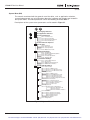
Volume Table of Contents
SVX9000 AF Drives User Manaul
SAFETY . . . . . . . . . . . . . . . . . . . . . . . . . . . . . . . . . . . . . . . . . . . . . . . . . .
CHAPTER 1 — OVERVIEW . . . . . . . . . . . . . . . . . . . . . . . . . . . . . . . . . . .
CHAPTER 2 — MOUNTING . . . . . . . . . . . . . . . . . . . . . . . . . . . . . . . . . .
CHAPTER 3 — POWER WIRING . . . . . . . . . . . . . . . . . . . . . . . . . . . . . . .
CHAPTER 4 — CONTROL WIRING . . . . . . . . . . . . . . . . . . . . . . . . . . . .
CHAPTER 5 — MENU INFORMATION . . . . . . . . . . . . . . . . . . . . . . . . .
CHAPTER 6 — START-UP . . . . . . . . . . . . . . . . . . . . . . . . . . . . . . . . . . .
APPENDIX A — TECHNICAL DATA . . . . . . . . . . . . . . . . . . . . . . . . . . . .
APPENDIX B — FAULT AND WARNING CODES . . . . . . . . . . . . . . . . .
v
1-1
2-1
3-1
4-1
5-1
6-1
A-1
B-1
SVX9000 AF Drives Application Manual
SAFETY . . . . . . . . . . . . . . . . . . . . . . . . . . . . . . . . . . . . . . . . . . . . . . . . . .
CHAPTER 1 — BASIC APPLICATION . . . . . . . . . . . . . . . . . . . . . . . . . . .
CHAPTER 2 — STANDARD APPLICATION . . . . . . . . . . . . . . . . . . . . . .
CHAPTER 3 — LOCAL/REMOTE APPLICATION . . . . . . . . . . . . . . . . . .
CHAPTER 4 — MULTI-STEP SPEED CONTROL APPLICATION . . . . . .
CHAPTER 5 — PID CONTROL APPLICATION . . . . . . . . . . . . . . . . . . . .
CHAPTER 6 — MULTI-PURPOSE CONTROL APPLICATION . . . . . . . .
CHAPTER 7 — PUMP AND FAN CONTROL APPLICATION . . . . . . . . .
CHAPTER 8 — DESCRIPTION OF PARAMETERS . . . . . . . . . . . . . . . . .
APPENDIX A — ADDITIONAL INFORMATION . . . . . . . . . . . . . . . . . . .
For more information visit: www.eatonelectrical.com
vii
1-1
2-1
3-1
4-1
5-1
6-1
7-1
8-1
A-1
MN04003002E
For Sales and Support, Contact Walker EMD • Toll-free: (800) 876-4444 • Tel: (203) 426-7700 • Fax: (203) 426-7800 • www.walkeremd.com
SVX9000 AF Drives
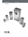
User Manual
Supersedes October 2003
April 2004
MN04003002E
For more information visit: www.eatonelectrical.com
For Sales and Support, Contact Walker EMD • Toll-free: (800) 876-4444 • Tel: (203) 426-7700 • Fax: (203) 426-7800 • www.walkeremd.com
For Sales and Support, Contact Walker EMD • Toll-free: (800) 876-4444 • Tel: (203) 426-7700 • Fax: (203) 426-7800 • www.walkeremd.com
SVX9000 AF Drive User Manual
April 2004
Important Notice – Please Read
The product discussed in this literature is subject to terms and conditions outlined in Eaton
Electrical Inc. selling policies. The sole source governing the rights and remedies of any
purchaser of this equipment is the relevant Eaton Electrical Inc. selling policy.
NO WARRANTIES, EXPRESS OR IMPLIED, INCLUDING WARRANTIES OF FITNESS FOR A
PARTICULAR PURPOSE OR MERCHANTABILITY, OR WARRANTIES ARISING FROM COURSE
OF DEALING OR USAGE OF TRADE, ARE MADE REGARDING THE INFORMATION,
RECOMMENDATIONS AND DESCRIPTIONS CONTAINED HEREIN. In no event will Eaton
Electrical Inc. be responsible to the purchaser or user in contract, in tort (including
negligence), strict liability or otherwise for any special, indirect, incidental or consequential
damage or loss whatsoever, including but not limited to damage or loss of use of equipment,
plant or power system, cost of capital, loss of power, additional expenses in the use of
existing power facilities, or claims against the purchaser or user by its customers resulting
from the use of the information, recommendations and descriptions contained herein.
The information contained in this manual is subject to change without notice.
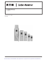
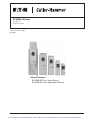
Cover Photo: Cutler-Hammer® SVX9000 AF Drives.
MN04003002E
For more information visit: www.eatonelectrical.com
For Sales and Support, Contact Walker EMD • Toll-free: (800) 876-4444 • Tel: (203) 426-7700 • Fax: (203) 426-7800 • www.walkeremd.com
i
SVX9000 AF Drive User Manual
April 2004
Table of Contents
ii
LIST OF FIGURES . . . . . . . . . . . . . . . . . . . . . . . . . . . . . . . . . . . . . . . . . . . . . . . . . . . . . . . . .
LIST OF TABLES . . . . . . . . . . . . . . . . . . . . . . . . . . . . . . . . . . . . . . . . . . . . . . . . . . . . . . . . . .
SAFETY . . . . . . . . . . . . . . . . . . . . . . . . . . . . . . . . . . . . . . . . . . . . . . . . . . . . . . . . . . . . . . . . .
Definitions and Symbols . . . . . . . . . . . . . . . . . . . . . . . . . . . . . . . . . . . . . . . . . . . . . . .
Hazardous High Voltage . . . . . . . . . . . . . . . . . . . . . . . . . . . . . . . . . . . . . . . . . . . . . . .
Warnings and Cautions . . . . . . . . . . . . . . . . . . . . . . . . . . . . . . . . . . . . . . . . . . . . . . . .
iii
iv
v
v
v
vi
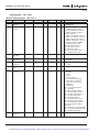
CHAPTER 1 — OVERVIEW . . . . . . . . . . . . . . . . . . . . . . . . . . . . . . . . . . . . . . . . . . . . . . . . .
How to Use This Manual . . . . . . . . . . . . . . . . . . . . . . . . . . . . . . . . . . . . . . . . . . . . . . .
Receiving and Inspection. . . . . . . . . . . . . . . . . . . . . . . . . . . . . . . . . . . . . . . . . . . . . . .
Open SVX9000 Catalog Numbers. . . . . . . . . . . . . . . . . . . . . . . . . . . . . . . . . . . . . . . .
1-1
1-1
1-1
1-2
CHAPTER 2 — MOUNTING . . . . . . . . . . . . . . . . . . . . . . . . . . . . . . . . . . . . . . . . . . . . . . . . .
Space Requirements . . . . . . . . . . . . . . . . . . . . . . . . . . . . . . . . . . . . . . . . . . . . . . . . . .
Environmental Requirements . . . . . . . . . . . . . . . . . . . . . . . . . . . . . . . . . . . . . . . . . . .
Standard Mounting Instructions . . . . . . . . . . . . . . . . . . . . . . . . . . . . . . . . . . . . . . . . .
2-1
2-1
2-2
2-2
CHAPTER 3 — POWER WIRING . . . . . . . . . . . . . . . . . . . . . . . . . . . . . . . . . . . . . . . . . . . . .
Guidelines . . . . . . . . . . . . . . . . . . . . . . . . . . . . . . . . . . . . . . . . . . . . . . . . . . . . . . . . . . .
UL Compatible Cable Selection and Installation . . . . . . . . . . . . . . . . . . . . . . . . . . . .
Installation Instructions . . . . . . . . . . . . . . . . . . . . . . . . . . . . . . . . . . . . . . . . . . . . . . . .
Standard Wiring Diagrams and Terminal Locations . . . . . . . . . . . . . . . . . . . . . . . . .
Power and Motor Wiring Terminal Photos. . . . . . . . . . . . . . . . . . . . . . . . . . . . . . . . .
Checking the Cable and Motor Insulation . . . . . . . . . . . . . . . . . . . . . . . . . . . . . . . . .
3-1
3-1
3-2
3-4
3-7
3-10
3-16
CHAPTER 4 — CONTROL WIRING . . . . . . . . . . . . . . . . . . . . . . . . . . . . . . . . . . . . . . . . . . .
General Information. . . . . . . . . . . . . . . . . . . . . . . . . . . . . . . . . . . . . . . . . . . . . . . . . . .
Control Wiring Details . . . . . . . . . . . . . . . . . . . . . . . . . . . . . . . . . . . . . . . . . . . . . . . . .
4-1
4-1
4-3
CHAPTER 5 — MENU INFORMATION . . . . . . . . . . . . . . . . . . . . . . . . . . . . . . . . . . . . . . . .
Keypad Operation . . . . . . . . . . . . . . . . . . . . . . . . . . . . . . . . . . . . . . . . . . . . . . . . . . . .
Menu Navigation . . . . . . . . . . . . . . . . . . . . . . . . . . . . . . . . . . . . . . . . . . . . . . . . . . . . .
5-1
5-1
5-3
CHAPTER 6 — START-UP . . . . . . . . . . . . . . . . . . . . . . . . . . . . . . . . . . . . . . . . . . . . . . . . . .
Safety Precautions . . . . . . . . . . . . . . . . . . . . . . . . . . . . . . . . . . . . . . . . . . . . . . . . . . . .
Sequence of Operation . . . . . . . . . . . . . . . . . . . . . . . . . . . . . . . . . . . . . . . . . . . . . . . .
6-1
6-1
6-2
APPENDIX A — TECHNICAL DATA . . . . . . . . . . . . . . . . . . . . . . . . . . . . . . . . . . . . . . . . . . .
General . . . . . . . . . . . . . . . . . . . . . . . . . . . . . . . . . . . . . . . . . . . . . . . . . . . . . . . . . . . . .
Specifications . . . . . . . . . . . . . . . . . . . . . . . . . . . . . . . . . . . . . . . . . . . . . . . . . . . . . . . .
Power Ratings. . . . . . . . . . . . . . . . . . . . . . . . . . . . . . . . . . . . . . . . . . . . . . . . . . . . . . . .
Power Loss and Switching Frequency . . . . . . . . . . . . . . . . . . . . . . . . . . . . . . . . . . . .
Dimensions . . . . . . . . . . . . . . . . . . . . . . . . . . . . . . . . . . . . . . . . . . . . . . . . . . . . . . . . . .
EMC Capability . . . . . . . . . . . . . . . . . . . . . . . . . . . . . . . . . . . . . . . . . . . . . . . . . . . . . . .
Declaration of Conformity . . . . . . . . . . . . . . . . . . . . . . . . . . . . . . . . . . . . . . . . . . . . . .
Warranty and Liability Information. . . . . . . . . . . . . . . . . . . . . . . . . . . . . . . . . . . . . . .
A-1
A-1
A-2
A-4
A-6
A-10
A-15
A-15
A-16
APPENDIX B — FAULT AND WARNING CODES . . . . . . . . . . . . . . . . . . . . . . . . . . . . . . . .
B-1
For more information visit: www.eatonelectrical.com
MN04003002E
For Sales and Support, Contact Walker EMD • Toll-free: (800) 876-4444 • Tel: (203) 426-7700 • Fax: (203) 426-7800 • www.walkeremd.com
SVX9000 AF Drive User Manual
April 2004
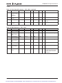
List of Figures
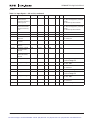
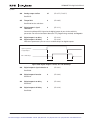
Figure 2-1: Mounting Space Requirements. . . . . . . . . . . . . . . . . . . . . . . . . . . . . . . . . . . . .
Figure 3-1: Input Power and Motor Cable Stripping and Wire Lengths . . . . . . . . . . . . . .
Figure 3-2: Wiring Plate . . . . . . . . . . . . . . . . . . . . . . . . . . . . . . . . . . . . . . . . . . . . . . . . . . . .
Figure 3-3: Ground Terminal Locations . . . . . . . . . . . . . . . . . . . . . . . . . . . . . . . . . . . . . . . .
Figure 3-4: Cable Protection Plate . . . . . . . . . . . . . . . . . . . . . . . . . . . . . . . . . . . . . . . . . . . .
Figure 3-5: Principle Wiring Diagram of SVX Power Unit,
FR4 to FR5 and FR6 (690V) . . . . . . . . . . . . . . . . . . . . . . . . . . . . . . . . . . . . . . . . . . . . . . .
Figure 3-6: Principle Wiring Diagram of SVX Power Unit,
FR6 (500V), FR7 and FR8 . . . . . . . . . . . . . . . . . . . . . . . . . . . . . . . . . . . . . . . . . . . . . . . .
Figure 3-7: Principle Wiring Diagram of SVX Power Unit, FR9 to FR10 . . . . . . . . . . . . . .
Figure 3-8: FR4 Power and Motor Wiring Terminals . . . . . . . . . . . . . . . . . . . . . . . . . . . . .
Figure 3-9: FR5 Power and Motor Wiring Terminals . . . . . . . . . . . . . . . . . . . . . . . . . . . . .
Figure 3-10: FR6 Power and Motor Wiring Terminals . . . . . . . . . . . . . . . . . . . . . . . . . . . .
Figure 3-11: FR7 Power and Motor Wiring Terminals . . . . . . . . . . . . . . . . . . . . . . . . . . . .
Figure 3-12: FR8 Power and Motor Wiring Terminals . . . . . . . . . . . . . . . . . . . . . . . . . . . .
Figure 3-13: FR9 Power and Motor Wiring Terminals . . . . . . . . . . . . . . . . . . . . . . . . . . . .
Figure 4-1: Option Board Slots . . . . . . . . . . . . . . . . . . . . . . . . . . . . . . . . . . . . . . . . . . . . . . .
Figure 4-2: Option Board A9 Wiring Diagram . . . . . . . . . . . . . . . . . . . . . . . . . . . . . . . . . . .
Figure 4-3: Option Board A9 Jumper Location and Settings . . . . . . . . . . . . . . . . . . . . . .
Figure 4-4: Option Board A2 Wiring Diagram . . . . . . . . . . . . . . . . . . . . . . . . . . . . . . . . . . .
Figure 4-5: Option Board A2 Terminal Locations . . . . . . . . . . . . . . . . . . . . . . . . . . . . . . . .
Figure 4-6: Positive/Negative Logic . . . . . . . . . . . . . . . . . . . . . . . . . . . . . . . . . . . . . . . . . . .
Figure 5-1: Keypad and Display . . . . . . . . . . . . . . . . . . . . . . . . . . . . . . . . . . . . . . . . . . . . . .
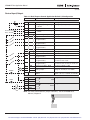
Figure 5-2: Main Menu Navigation . . . . . . . . . . . . . . . . . . . . . . . . . . . . . . . . . . . . . . . . . . .
Figure 5-3: Parameter Menu Structure Example . . . . . . . . . . . . . . . . . . . . . . . . . . . . . . . .
Figure 5-4: Keypad Control Menu . . . . . . . . . . . . . . . . . . . . . . . . . . . . . . . . . . . . . . . . . . . .
Figure 5-5: Active Fault Display Example . . . . . . . . . . . . . . . . . . . . . . . . . . . . . . . . . . . . . .
Figure 5-6: Sample Fault History Display . . . . . . . . . . . . . . . . . . . . . . . . . . . . . . . . . . . . . .
Figure 5-7: System Menu Structure . . . . . . . . . . . . . . . . . . . . . . . . . . . . . . . . . . . . . . . . . . .
Figure 5-8: Expander Board Menu Structure . . . . . . . . . . . . . . . . . . . . . . . . . . . . . . . . . . .
Figure 5-9: Digital Inputs — DIN1, DIN2, DIN3 Status . . . . . . . . . . . . . . . . . . . . . . . . . . . .
Figure 5-10: Digital Inputs — DIN4, DIN5, DIN6 Status . . . . . . . . . . . . . . . . . . . . . . . . . . .
Figure 5-11: Digital and Relay Outputs — DO1, RO1, RO2 Status . . . . . . . . . . . . . . . . . .
Figure 5-12: Operate Menu Navigation . . . . . . . . . . . . . . . . . . . . . . . . . . . . . . . . . . . . . . . .
Figure A-1: SVX9000 Block Diagram . . . . . . . . . . . . . . . . . . . . . . . . . . . . . . . . . . . . . . . . . .
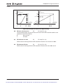
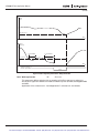
Figure A-2: Power Loss as Function of Switching Frequency —
3/4 – 3 hp 230V, 1 – 5 hp 480V . . . . . . . . . . . . . . . . . . . . . . . . . . . . . . . . . . . . . . . . . . . .
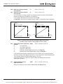
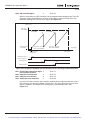
Figure A-3: Power Loss as Function of Switching Frequency —
5 – 7-1/2 hp 230V, 7-1/2 – 15 hp 480V . . . . . . . . . . . . . . . . . . . . . . . . . . . . . . . . . . . . . .
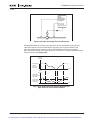
Figure A-4: Power Loss as Function of Switching Frequency —
10 – 15 hp 230V, 20 – 30 hp 480V . . . . . . . . . . . . . . . . . . . . . . . . . . . . . . . . . . . . . . . . . .
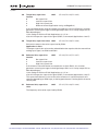
Figure A-5: Power Loss as Function of Switching Frequency —
20 – 30 hp 230V, 40 – 60 hp 480V . . . . . . . . . . . . . . . . . . . . . . . . . . . . . . . . . . . . . . . . . .
Figure A-6: Power Loss as Function of Switching Frequency —
75 – 125 hp 480V . . . . . . . . . . . . . . . . . . . . . . . . . . . . . . . . . . . . . . . . . . . . . . . . . . . . . . .
Figure A-7: Power Loss as Function of Switching Frequency —
150 – 200 hp 480V . . . . . . . . . . . . . . . . . . . . . . . . . . . . . . . . . . . . . . . . . . . . . . . . . . . . . .
MN04003002E
2-1
3-4
3-5
3-5
3-6
3-7
3-8
3-9
3-10
3-11
3-12
3-13
3-14
3-15
4-1
4-3
4-5
4-5
4-6
4-6
5-1
5-4
5-5
5-6
5-7
5-9
5-10
5-18
5-19
5-19
5-19
5-21
A-2
For more information visit: www.eatonelectrical.com
For Sales and Support, Contact Walker EMD • Toll-free: (800) 876-4444 • Tel: (203) 426-7700 • Fax: (203) 426-7800 • www.walkeremd.com
A-6
A-7
A-7
A-8
A-8
A-9
iii
SVX9000 AF Drive User Manual
April 2004
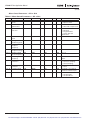
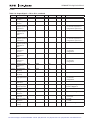
List of Figures, continued
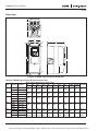
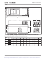
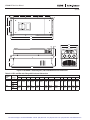
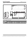
Figure A-8: NEMA Type 1 Enclosure Dimensions . . . . . . . . . . . . . . . . . . . . . . . . . . . . . . .
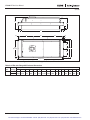
Figure A-9: NEMA 1 and NEMA 12 with Flange Kit, FR4,
FR5 and FR6 Enclosure Dimensions . . . . . . . . . . . . . . . . . . . . . . . . . . . . . . . . . . . . . .
Figure A-10: NEMA 1 with Flange Kit, FR7 and FR8 Enclosure Dimensions . . . . . . . . . .
Figure A-11: FR9 Enclosure Dimensions . . . . . . . . . . . . . . . . . . . . . . . . . . . . . . . . . . . . . .
Figure A-12: FR9 with Flange Kit Enclosure Dimensions . . . . . . . . . . . . . . . . . . . . . . . . .
A-10
A-11
A-12
A-13
A-14
List of Tables
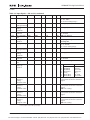
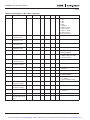
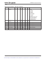
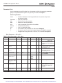
Table 1-1: SVX9000 AF Drive Catalog Numbering System . . . . . . . . . . . . . . . . . . . . . . . .
Table 2-1: Space Requirements for Mounting a SVX9000 Drive. . . . . . . . . . . . . . . . . . . .
Table 2-2: Cooling Airflow Requirements . . . . . . . . . . . . . . . . . . . . . . . . . . . . . . . . . . . . . .
Table 3-1: Cable Spacings . . . . . . . . . . . . . . . . . . . . . . . . . . . . . . . . . . . . . . . . . . . . . . . . . .
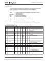
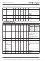
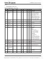
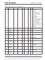
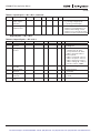
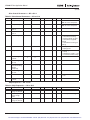
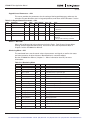
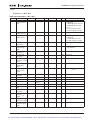
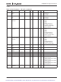
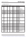
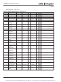
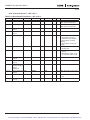
Table 3-2: Cable and Fuse Sizes – 230V Ratings. . . . . . . . . . . . . . . . . . . . . . . . . . . . . . . . .
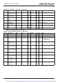
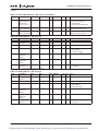
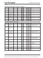
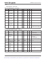
Table 3-3: Cable and Fuse Sizes – 480V Ratings. . . . . . . . . . . . . . . . . . . . . . . . . . . . . . . . .
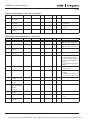
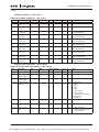
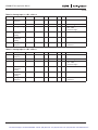
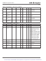
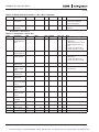
Table 3-4: Cable and Fuse Sizes – 575V Ratings. . . . . . . . . . . . . . . . . . . . . . . . . . . . . . . . .
Table 3-5: Maximum Symmetrical Supply Current . . . . . . . . . . . . . . . . . . . . . . . . . . . . . .
Table 3-6: Power Connection Tightening Torque . . . . . . . . . . . . . . . . . . . . . . . . . . . . . . . .
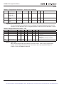
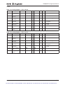
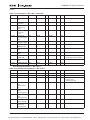
Table 3-7: Power and Motor Cable Stripping Lengths . . . . . . . . . . . . . . . . . . . . . . . . . . . .
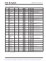
Table 4-1: Tightening Torques of Terminals . . . . . . . . . . . . . . . . . . . . . . . . . . . . . . . . . . . .
Table 4-2: Control Wiring Instructions. . . . . . . . . . . . . . . . . . . . . . . . . . . . . . . . . . . . . . . . .
Table 4-3: Option Board A9 Terminal Descriptions . . . . . . . . . . . . . . . . . . . . . . . . . . . . . .
Table 4-4: Option Board A2 Terminal Descriptions . . . . . . . . . . . . . . . . . . . . . . . . . . . . . .
Table 5-1: LCD Status Indicators . . . . . . . . . . . . . . . . . . . . . . . . . . . . . . . . . . . . . . . . . . . . .
Table 5-2: LED Status Indicators . . . . . . . . . . . . . . . . . . . . . . . . . . . . . . . . . . . . . . . . . . . . .
Table 5-3: Navigation Buttons . . . . . . . . . . . . . . . . . . . . . . . . . . . . . . . . . . . . . . . . . . . . . . .
Table 5-4: Fault Types . . . . . . . . . . . . . . . . . . . . . . . . . . . . . . . . . . . . . . . . . . . . . . . . . . . . . .
Table 5-5: Fault Time Data . . . . . . . . . . . . . . . . . . . . . . . . . . . . . . . . . . . . . . . . . . . . . . . . . .
Table 5-6: Total Counters . . . . . . . . . . . . . . . . . . . . . . . . . . . . . . . . . . . . . . . . . . . . . . . . . . .
Table 5-7: Trip Counters . . . . . . . . . . . . . . . . . . . . . . . . . . . . . . . . . . . . . . . . . . . . . . . . . . . .
Table 5-8: Software Information . . . . . . . . . . . . . . . . . . . . . . . . . . . . . . . . . . . . . . . . . . . . .
Table 5-9: Application Information . . . . . . . . . . . . . . . . . . . . . . . . . . . . . . . . . . . . . . . . . . .
Table 5-10: Hardware Information . . . . . . . . . . . . . . . . . . . . . . . . . . . . . . . . . . . . . . . . . . . .
Table 5-11: Expander Board Information . . . . . . . . . . . . . . . . . . . . . . . . . . . . . . . . . . . . . .
Table 5-12: Monitoring Menu Items — Standard Application Example . . . . . . . . . . . . . .
Table 5-13: Operate Menu Items — Standard Application Example . . . . . . . . . . . . . . . .
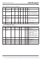
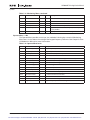
Table A-1: SVX9000 Drive Specifications . . . . . . . . . . . . . . . . . . . . . . . . . . . . . . . . . . . . . .
Table A-2: Output Power Ratings — 230V CT . . . . . . . . . . . . . . . . . . . . . . . . . . . . . . . . . .
Table A-3: Output Power Ratings — 480V CT . . . . . . . . . . . . . . . . . . . . . . . . . . . . . . . . . .
Table A-4: Output Power Ratings — 575V CT . . . . . . . . . . . . . . . . . . . . . . . . . . . . . . . . . .
Table A-5: NEMA Type 1/Type 12 Enclosure Dimensions . . . . . . . . . . . . . . . . . . . . . . . . .
Table A-6: FR4, FR5 and FR6 with Flange Kit Enclosure Dimensions . . . . . . . . . . . . . . . .
Table A-7: FR7 and FR8 with Flange Kit Enclosure Dimensions . . . . . . . . . . . . . . . . . . . .
Table A-8: FR9 Enclosure Dimensions. . . . . . . . . . . . . . . . . . . . . . . . . . . . . . . . . . . . . . . . .
Table A-9: FR9 with Flange Kit Enclosure Dimensions . . . . . . . . . . . . . . . . . . . . . . . . . . .
Table B-1: Fault Codes . . . . . . . . . . . . . . . . . . . . . . . . . . . . . . . . . . . . . . . . . . . . . . . . . . . . .
iv
For more information visit: www.eatonelectrical.com
1-2
2-1
2-2
3-1
3-2
3-2
3-3
3-3
3-3
3-4
4-2
4-2
4-4
4-6
5-1
5-2
5-2
5-8
5-8
5-15
5-15
5-16
5-16
5-16
5-17
5-19
5-20
A-2
A-4
A-5
A-5
A-10
A-11
A-12
A-13
A-14
B-1
MN04003002E
For Sales and Support, Contact Walker EMD • Toll-free: (800) 876-4444 • Tel: (203) 426-7700 • Fax: (203) 426-7800 • www.walkeremd.com
SVX9000 AF Drive User Manual
April 2004
Safety
Definitions and Symbols
WARNING
This symbol indicates high voltage. It calls your attention to items
or operations that could be dangerous to you and other persons
operating this equipment. Read the message and follow the
instructions carefully.
This symbol is the “Safety Alert Symbol.” It occurs with either of
two signal words: CAUTION or WARNING, as described below.
WARNING
Indicates a potentially hazardous situation which, if not avoided,
can result in serious injury or death.
CAUTION
Indicates a potentially hazardous situation which, if not avoided,
can result in minor to moderate injury, or serious damage to the
equipment. The situation described in the CAUTION may, if not
avoided, lead to serious results. Important safety measures are
described in CAUTION (as well as WARNING).
Hazardous High Voltage
WARNING
Motor control equipment and electronic controllers are connected
to hazardous line voltages. When servicing drives and electronic
controllers, there may be exposed components with housings or
protrusions at or above line potential. Extreme care should be taken
to protect against shock.
• Stand on an insulating pad and make it a habit to use only one
hand when checking components.
• Always work with another person in case an emergency occurs.
• Disconnect power before checking controllers or performing
maintenance.
• Be sure equipment is properly grounded.
• Wear safety glasses whenever working on electronic controllers
or rotating machinery.
MN04003002E
For more information visit: www.eatonelectrical.com
For Sales and Support, Contact Walker EMD • Toll-free: (800) 876-4444 • Tel: (203) 426-7700 • Fax: (203) 426-7800 • www.walkeremd.com
v
SVX9000 AF Drive User Manual
April 2004
Warnings and Cautions
Read this manual thoroughly and make sure you understand the procedures before you
attempt to install, set up, or operate this Cutler-Hammer® SVX9000 Adjustable Frequency
Drive from Eaton Electrical®.
Warnings
WARNING
Be sure to ground the unit following the instructions in this manual.
Ungrounded units may cause electric shock and/or fire.
WARNING
This equipment should be installed, adjusted, and serviced by
qualified electrical maintenance personnel familiar with the
construction and operation of this type of equipment and the
hazards involved. Failure to observe this precaution could result in
death or severe injury.
WARNING
Components within the SVX9000 power unit are live when the drive
is connected to power. Contact with this voltage is extremely
dangerous and may cause death or severe injury.
WARNING
Line terminals (L1, L2, L3), motor terminals (U, V, W) and the DClink/brake resistor terminals (-/+) are live when the drive is
connected to power, even if the motor is not running. Contact with
this voltage is extremely dangerous and may cause death or severe
injury.
WARNING
Even though the control I/O-terminals are isolated from line
voltage, the relay outputs and other I/O-terminals may have
dangerous voltage present even when the drive is disconnected
from power. Contact with this voltage is extremely dangerous and
may cause death or severe injury.
WARNING
The SVX9000 drive has a large capacitive leakage current during
operation, which can cause enclosure parts to be above ground
potential. Proper grounding, as described in this manual, is
required. Failure to observe this precaution could result in death or
severe injury.
WARNING
Before applying power to the SVX9000 drive, make sure that the
front and cable covers are closed and fastened to prevent exposure
to potential electrical fault conditions. Failure to observe this
precaution could result in death or severe injury.
vi
For more information visit: www.eatonelectrical.com
MN04003002E
For Sales and Support, Contact Walker EMD • Toll-free: (800) 876-4444 • Tel: (203) 426-7700 • Fax: (203) 426-7800 • www.walkeremd.com
SVX9000 AF Drive User Manual
April 2004
WARNING
An upstream disconnect/protective device must be provided as
required by the National Electric Code (NEC). Failure to follow this
precaution may result in death or severe injury.
WARNING
Before opening the SVX9000 drive covers:
• Disconnect all power to the SVX9000 drive.
• Wait a minimum of 5 (five) minutes after all the lights on the
keypad are off. This allows time for the DC bus capacitors to
discharge.
• A hazard voltage may still remain in the DC bus capacitors even
if the power has been turned off. Confirm that the capacitors
have fully discharged by measuring their voltage using a
multimeter set to measure DC voltage.
Failure to follow the above precautions may cause death or severe
injury.
Cautions
CAUTION
Do not perform any meggar or voltage withstand tests on any part
of the SVX9000 drive or its components. Improper testing may
result in damage.
CAUTION
Prior to any tests or measurements of the motor or the motor cable,
disconnect the motor cable at the SVX9000 output terminals (U, V,
W) to avoid damaging the SVX9000 during motor or cable testing.
CAUTION
Do not touch any components on the circuit boards. Static voltage
discharge may damage the components.
CAUTION
Any electrical or mechanical modification to this equipment
without prior written consent of Eaton’s Cutler-Hammer business
unit will void all warranties and may result in a safety hazard in
addition and voiding of the UL listing.
CAUTION
Install the SVX9000 drive on flame-resistant material such as a steel
plate to reduce the risk of fire.
CAUTION
Install the SVX9000 drive on a perpendicular surface that is able to
support the weight of the drive and is not subject to vibration, to
lessen the risk of the drive falling and being damaged and/or
causing personal injury.
MN04003002E
For more information visit: www.eatonelectrical.com
For Sales and Support, Contact Walker EMD • Toll-free: (800) 876-4444 • Tel: (203) 426-7700 • Fax: (203) 426-7800 • www.walkeremd.com
vii
SVX9000 AF Drive User Manual
April 2004
CAUTION
Prevent foreign material such as wire clippings or metal shavings
from entering the drive enclosure, as this may cause arcing
damage and fire.
CAUTION
Install the SVX9000 drive in a well-ventilated room that is not
subject to temperature extremes, high humidity, or condensation,
and avoid locations that are directly exposed to sunlight, or have
high concentrations of dust, corrosive gas, explosive gas,
inflammable gas, grinding fluid mist, etc. Improper installation may
result in a fire hazard.
Motor and Equipment Safety
CAUTION
Before starting the motor, check that the motor is mounted properly
and aligned with the driven equipment. Ensure that starting the
motor will not cause personal injury or damage equipment
connected to the motor.
CAUTION
Set the maximum motor speed (frequency) in the HXV9000 drive
according to the requirements of the motor and the equipment
connected to it. Incorrect maximum frequency settings can cause
motor or equipment damage and personal injury.
CAUTION
Before reversing the motor rotation direction, ensure that this will
not cause personal injury or equipment damage.
CAUTION
Make sure that no power correction capacitors are connected to the
SVX9000 output or the motor terminals to prevent SVX9000
malfunction and potential damage.
CAUTION
Make sure that the SVX9000 output terminals (U, V, W) are not
connected to the utility line power as severe damage to the
SVX9000 may occur.
viii
For more information visit: www.eatonelectrical.com
MN04003002E
For Sales and Support, Contact Walker EMD • Toll-free: (800) 876-4444 • Tel: (203) 426-7700 • Fax: (203) 426-7800 • www.walkeremd.com
SVX9000 AF Drive User Manual
April 2004
Chapter 1 — Overview
This chapter describes the purpose and contents of this manual, the receiving inspection
recommendations and the Cutler-Hammer® SVX9000 catalog numbering system.
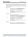
How to Use This Manual
The purpose of this manual is to provide you with information necessary to install, set and
customize parameters, start up, troubleshoot and maintain the Cutler-Hammer SVX9000
drive by Eaton Electrical®. To provide for safe installation and operation of the equipment,
read the safety guidelines at the beginning of this manual and follow the procedures outlined
in the following chapters before connecting power to the SVX9000. Keep this operating
manual handy and distribute to all users, technicians and maintenance personnel for
reference.
Chapter 1 – Overview is the chapter you are reading now.
Chapter 2 – Mounting
Chapter 3 – Power Wiring
Chapter 4 – Control Wiring
Chapter 5 – Menu Information
Chapter 6 – Start-Up
Appendix A – Technical Data
Appendix B – Fault and Warning Codes
Receiving and Inspection
This SVX9000 AC drive has met a stringent series of factory quality requirements before
shipment. It is possible that packaging or equipment damage may have occurred during
shipment. After receiving your SVX9000 drive, please check for the following:
●
Check to make sure that the package(s) includes the SVX9000 drive, the User Manual,
and rubber conduit covers, screws, conduit plate and ground straps.
●
Inspect the unit to ensure it was not damaged during shipment.
●
Make sure that the part number indicated on the nameplate corresponds with the
Catalog Number on your order.
If shipping damage has occurred, please contact and file a claim with the carrier involved
immediately.
If the delivery does not correspond to your order, please contact your Eaton Electrical
Cutler-Hammer representative.
Note: Do not destroy the packing. The template printed on the protective cardboard can be
used for marking the mounting points of the SVX9000 on the wall or cabinet.
MN04003002E
For more information visit: www.eatonelectrical.com
For Sales and Support, Contact Walker EMD • Toll-free: (800) 876-4444 • Tel: (203) 426-7700 • Fax: (203) 426-7800 • www.walkeremd.com
1-1
SVX9000 AF Drive User Manual
April 2004
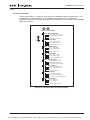
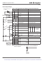
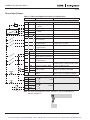
Open SVX9000 Catalog Numbers
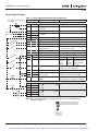
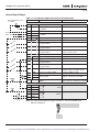
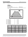
Table 1-1: SVX9000 AF Drive Catalog Numbering System
SVX 007A 1 - 4 A 1 B 1
Expansion Slots 3 through 5
Product
• Option boards be selected from left
to right, in alpha-numeric order.
• Characters to be left blank if no
options are selected
SVX = SVX Industrial Drive
SPX = SPX Drive
(Fr10 and larger only)
Horsepower (CT) F07 = 3/4
001 = 1
F15 = 1-1/2
002 = 2
003 = 3
004 = 5 VT Only
005 = 5
006 = 7-1/2 VT Only
007 = 7-1/2
010 = 10
015 = 15
020 = 20
025 = 25
Board Modifications
030 = 30
040 = 40
050 = 50
060 = 60
075 = 75
100 = 100
125 = 125
150 = 150
200 = 200
250 = 250
300 = 300
350 = 350
1 = Standard Boards (A9, A2)
Braking
N = No Brake Chopper B = Internal Brake Chopper Input Options 1 = 3-Phase, EMC H
2 = 3-Phase, EMC N
Keypad
AFD Software Series
A = Standard Software
Enclosure 0 = Open Chassis
1 = NEMA Type 1
2 = NEMA Type 12
1-2
A = AlphaNumeric
Voltage
2 = 208 – 230V
4 = 380 – 500V
5 = 525 – 690V
All 230V Drives and 480V Drives up to 200 hp (CT) are only available with Input Option 1.
480V Drives 250 hp (CT) or larger are only available with Input Option 2.
480V Drives up to 30 hp (CT) are only available with Brake Chopper Option B.
480V Drives 40 hp (CT) and larger come with Brake Chopper Option N as standard.
230V Drives up to 15 hp (CT) are only available with Brake Chopper Option B.
230V Drives 20 hp (CT) or larger come with Brake Chopper Option N as standard.
480V Drives 250 hp, 300 hp and 350 hp (CT) are only available with Enclosure Style 0 (Chassis).
For more information visit: www.eatonelectrical.com
MN04003002E
For Sales and Support, Contact Walker EMD • Toll-free: (800) 876-4444 • Tel: (203) 426-7700 • Fax: (203) 426-7800 • www.walkeremd.com
SVX9000 AF Drive User Manual
April 2004
Chapter 2 — Mounting
The SVX9000 drive may be mounted side-by-side or stacked vertically, as outlined in the
following section.
Space Requirements
To ensure proper air circulation and cooling, follow the guidelines below.
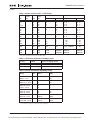
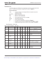
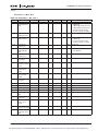
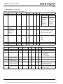
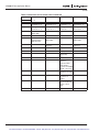
Table 2-1: Space Requirements for Mounting a SVX9000 Drive
Dimensions in Inches (mm) A
A2
B
C
Frame
Drive Type
4
230V, 1 – 3 hp VT, 3/4 – 3 hp CT
480V, 1 – 5 hp CT, 1-1/2 – 7-1/2 hp VT
230V, 5 – 10 hp VT, 5 – 7-1/2 hp CT
480V, 7-1/2 – 15 hp CT, 10 – 20 hp VT
230V, 15 – 20 hp VT, 10 – 15 hp CT
480V, 20 – 30 hp CT, 25 – 40 hp VT
575V, 2 – 25 hp CT, 3 – 30 hp VT
230V, 25 – 40 hp VT, 20 – 30 hp CT
480V, 40 – 60 hp CT, 50 – 75 hp VT
575V, 30 – 40 hp CT, 40 – 50 hp VT
480V, 75 – 125 hp CT, 100 – 150 hp VT
575V, 50 – 75 hp CT, 60 – 100 hp VT
480V, 200 – 250 hp VT, 150 – 200 hp CT
575V, 100 – 150 hp CT, 150 – 200 hp VT
5
6
7
8
9
0.8
(20)
1.2
(30)
1.2
(30)
—
—
—
D
0.8
(20)
0.8
(20)
0.8
(20)
3.9 (100) 2.0
(50)
4.7 (120) 2.4
(60)
6.3 (160) 3.1
(80)
3.1
(80)
—
3.1
(80)
11.8
(300)
3.9 (100)
3.1
(80)
2.0
(50)
5.9 (150) 3.1
(80)
—
3.1
(80)
11.8
(300)
15.7
(400)
7.9 (200)
9.8 (250)
13.8
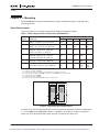
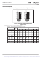
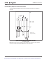
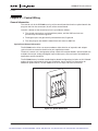
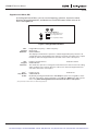
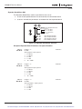
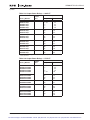
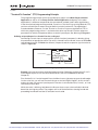
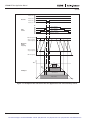
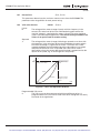
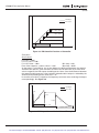
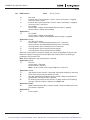
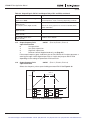
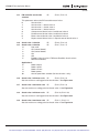
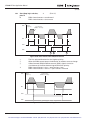
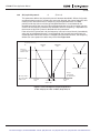
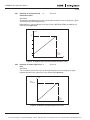
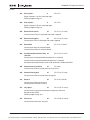
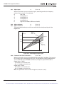
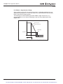
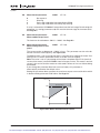
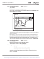
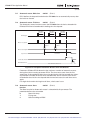
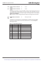
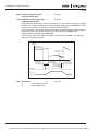
(350) Dimensions represent the minimum clearance needed when mounting a SVX9000. See Figure 2-1 below.
A = clearance around the SVX9000.
A2 = clearance needed to change the fan without disconnecting the motor cables.
B = distance between adjacent SVX9000s or between the SVX9000 and an enclosure wall.
C = clearance above the SVX9000.
D = clearance below the SVX9000.
Minimum clearance below the SVX9000 needed to change the fan.
C
B
A
A2
B
A
A2
D
Figure 2-1: Mounting Space Requirements.
If several units are mounted above each other, the clearance between the drives should equal
C + D (see Table 2-1 and Figure 2-1 above). In addition, the outlet air used for cooling the
lower unit must be directed away from the inlet air used by the upper unit.
MN04003002E
For more information visit: www.eatonelectrical.com
For Sales and Support, Contact Walker EMD • Toll-free: (800) 876-4444 • Tel: (203) 426-7700 • Fax: (203) 426-7800 • www.walkeremd.com
2-1
SVX9000 AF Drive User Manual
April 2004
Environmental Requirements
Ensure that the environment meets the requirements listed in Table A-1 of Appendix A for
any storage or operating situation.
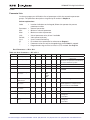
Table 2-2 specifies the minimum airflow required in the area where the drive will be
mounted.
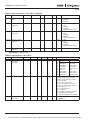
Table 2-2: Cooling Airflow Requirements
Drive Type
Cooling Air Required
230V, 3/4 – 3 hp CT
480V, 1 – 5 hp CT
41 cfm (70 m3/h)
230V, 5 – 7-1/2 hp CT
480V, 7-1/2 – 15 hp CT
112 cfm (190 m3/h)
230V, 10 – 15 hp CT
480V, 20 – 30 hp CT
575V, 2 – 25 hp CT
250 cfm (425 m3/h)
230V, 20 – 30 hp CT
480V, 40 – 60 hp CT
575V, 30 – 40 hp CT
250 cfm (425 m3/h)
480V, 75 – 125 hp CT
575V, 60 – 75 hp CT
383 cfm (650 m3/h)
480V, 150 – 200 hp CT
575V, 100 – 150 hp CT
765 cfm (1300 m3/h)
Standard Mounting Instructions
1. Measure the mounting space to ensure that it allows for the minimum space
surrounding the drive. Drive dimensions are in Appendix A.
2. Make sure the mounting surface is flat and strong enough to support the drive, is not
flammable, and is not subject to excessive motion or vibration.
3. Ensure that the minimum airflow requirements for your drive are met at the mounting
location.
4. Mark the location of the mounting holes on the mounting surface, using the template
provided on the cover of the cardboard shipping package.
5. Using fasteners appropriate to your drive and mounting surface, securely attach the
drive to the mounting surface using all 4 screws or bolts.
2-2
For more information visit: www.eatonelectrical.com
MN04003002E
For Sales and Support, Contact Walker EMD • Toll-free: (800) 876-4444 • Tel: (203) 426-7700 • Fax: (203) 426-7800 • www.walkeremd.com
SVX9000 AF Drive User Manual
April 2004
Chapter 3 — Power Wiring
Guidelines
To ensure proper wiring, use the following guidelines:
●
Use heat-resistant copper cables only, +75°C or higher.
●
The input line cable and line fuses must be sized in accordance with the rated input
current of the unit. See Tables 3-2 and 3-5.
●
Consistent with UL listing requirements, for maximum protection of the SVX9000 drive,
UL recognized fuses type RK5 should be used for 480V and 230V ratings.
●
If the motor temperature sensing is used for overload protection, the output cable size
may be selected based on the motor specifications.
●
If three or more shielded cables are used in parallel for the output on the larger units,
every cable must have its own overload protection.
●
Avoid placing the motor cables in long parallel lines with other cables.
●
If the motor cables run in parallel with other cables, note the minimum distances
between the motor cables and other cables given in Table 3-1 below:
Table 3-1: Cable Spacings
Minimum Distance Between
Cables in Feet (m)
Cable in Feet (m)
1 (0.3)
≤ 164 (50)
3.3 (1.0)
≤ 656 (200)
●
The spacings of Table 3-1 also apply between the motor cables and signal cables of
other systems.
●
The maximum length of the motor cables is as follows:
– 1 – 2 hp, 230V units, 328 ft. (100m)
– All other hp units, 984 ft. (300m)
MN04003002E
●
The motor cables should cross other cables at an angle of 90 degrees.
●
If conduit is being used for wiring, use separate conduits for the input power wiring,
the output power wiring, the signal wiring and the control wiring.
For more information visit: www.eatonelectrical.com
For Sales and Support, Contact Walker EMD • Toll-free: (800) 876-4444 • Tel: (203) 426-7700 • Fax: (203) 426-7800 • www.walkeremd.com
3-1
SVX9000 AF Drive User Manual
April 2004
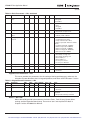
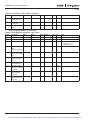
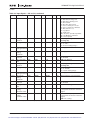
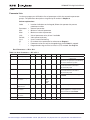
UL Compatible Cable Selection and Installation
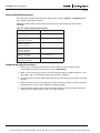
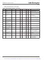
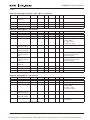
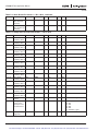
Use only copper wire with temperature rating of at least 75°C.
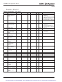
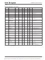
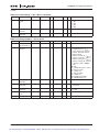
Table 3-2: Cable and Fuse Sizes – 230V Ratings
hp
Frame
Size
Il (A)
Fuse
(A) Wire Size Terminal Size
Power
Ground
Power
Ground
1
1-1/2
2
3
FR4
4.8
6.6
7.8
11
10
10
10
15
14
14
14
12
14
14
14
14
12 – 16
12 – 16
12 – 16
12 – 16
14 – 16
14 – 16
14 – 16
14 – 16
5
7-1/2
FR5
17.5
25
20
30
10
8
10
8
8 – 16
8 – 18
8 – 16
8 – 16
10
15
FR6
31
48
40
60
8
4
8
6
0 – 14
0 – 14
2 – 10
2 – 10
20
25
30
FR7
61
72
87
80
100
110
2
2
1/0
6
6
4
0 – 14
0 – 14
0 – 14
00 – 10
00 – 10
00 – 10
UL recognized type RK.
Based on a maximum environment of 104°F (40°C).
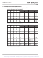
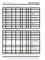
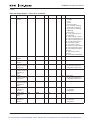
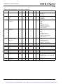
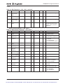
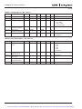
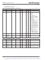
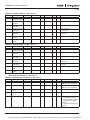
Table 3-3: Cable and Fuse Sizes – 480V Ratings
hp
Il (A)
Fuse
(A) Wire Size Terminal Size
Power
Ground
Power
Ground
1-1/2
2
3
5
FR4
3.3
4.3
5.6
7.6
10
10
10
10
14
14
14
14
14
14
14
14
12 – 16
12 – 16
12 – 16
12 – 16
14 – 16
14 – 16
14 – 16
14 – 16
7-1/2
10
15
FR5
12
16
23
15
20
30
12
10
8
12
10
8
8 – 16
8 – 16
8 – 16
8 – 16
8 – 16
8 – 16
20
25
30
FR6
31
38
46
35
50
60
8
6
4
8
8
6
0 – 14
0 – 14
0 – 14
2 – 10
2 – 10
2 – 10
40
50
60
FR7
61
72
87
80
100
110
2
2
1/0
6
6
4
0 – 14
0 – 14
0 – 14
2/0 – 10
2/0 – 10
2/0 – 10
75
100
125
FR8
105
140
170
125
175
200
2/0
4/0
300
2
1/0
2/0
3/0 – 4
350MCM – 3/0
350MCM – 3/0
3/0 – 4
3/0 – 4
3/0 – 4
150
200
FR9
205
261
250
350
350MCM
2x250MCM
3/0
3/0
350MCM – 2x3/0
350MCM – 2x3/0
3/0 – 4
3/0 – 4
250
300
350
FR10
300
385
460
400
450
600
2x250
2x300
2x400
300MCM
300MCM
300MCM
600MCM
600MCM
600MCM
600MCM
600MCM
600MCM
3-2
Frame
Size
UL recognized type RK.
Based on a maximum environment of 104°F (40°C).
For more information visit: www.eatonelectrical.com
MN04003002E
For Sales and Support, Contact Walker EMD • Toll-free: (800) 876-4444 • Tel: (203) 426-7700 • Fax: (203) 426-7800 • www.walkeremd.com
SVX9000 AF Drive User Manual
April 2004
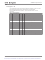
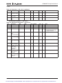
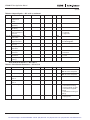
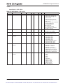
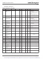
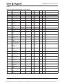
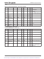
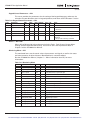
Table 3-4: Cable and Fuse Sizes – 575V Ratings
hp
2
3
5
7-1/2
Frame
Size
FR6
10
15
20
25
Il (A)
Fuse
(A) 3.3
4.5
7.5
10
Wire Size Terminal Size
Power
Ground
Power
Ground
10
10
10
15
14
14
14
12
14
14
14
14
14 – 0
14 – 0
14 – 0
14 – 0
14 – 2
14 – 2
14 – 2
14 – 2
13.5
18
22
27
20
30
35
40
10
10
8
8
12
10
8
8
14 – 0
14 – 0
14 – 0
14 – 0
14 – 2
14 – 2
14 – 2
14 – 2
30
40
FR7
34
41
50
60
6
4
8
6
14 – 0
14 – 0
10 – 0
10 – 0
50
60
75
100
FR8
52
62
80
100
80
100
125
175
2
1
1/0
3/0
6
6
6
6
4 – 3/0
4 – 3/0
4 – 3/0
4 – 3/0
4 – 3/0
4 – 3/0
4 – 3/0
4 – 3/0
125
150
FR9
125
144
200
250
4/0
350
2
1/0
2x3/0 – 350MCM
2x3/0 – 350MCM
4 – 3/0
4 – 3/0
200
250
300
FR10
208
261
325
350
450
500
2x250
2x300
2x350
300MCM
300MCM
300MCM
600MCM
600MCM
600MCM
600MCM
600MCM
600MCM
UL recognized type RK.
Based on a maximum environment of 104°F (40°C).
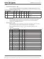
Table 3-5: Maximum Symmetrical Supply Current
Product
Voltage
Maximum RMS Symmetrical
Amperes on Supply Circuit
3/4 – 30 hp
230
100,000A
1-1/2 – 200 hp
480
100,000A
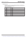
Table 3-6: Power Connection Tightening Torque
Rating
230V, 3/4 – 3 hp
480V, 1 – 5 hp
5
5
0.6
0.6
230V, 5 – 7-1/2 hp FR5
480V, 7-1/2 – 15 hp
13
13
1.5
1.5
230V, 10 – 15 hp
480V, 20 – 30 hp
575V, 2 – 25 hp
FR6
35
35
35
4
4
4
230V, 20 – 30 hp
480V, 40 – 60 hp
575V, 30 – 40 hp
FR7
85
85
85
10
10
10
480V, 75 – 125 hp
575V, 50 – 75 hp
FR8
340/187 340/187 40/22 40/22 480V, 150 – 200 hp FR9
575V, 100 – 175 hp
340/187 340/187 40/22 40/22 MN04003002E
Frame Tightening Torque Tightening Torque
Size
(in-lbs)
(Nm)
FR4
The isolation standoff of the bus bar will not withstand the listed tightening torque.
Use a wrench to apply a counter torque when tightening.
For more information visit: www.eatonelectrical.com
For Sales and Support, Contact Walker EMD • Toll-free: (800) 876-4444 • Tel: (203) 426-7700 • Fax: (203) 426-7800 • www.walkeremd.com
3-3
SVX9000 AF Drive User Manual
April 2004
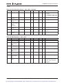
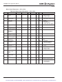
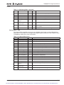
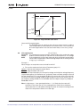
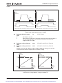
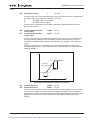
Installation Instructions
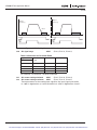
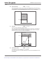
1. Strip the motor and input power cables as shown in Figure 3-1 and Table 3-7.
Ground
Ground
A1
C1
A2
C2
B1
D1
B2
D2
Power
Motor
Figure 3-1: Input Power and Motor Cable Stripping
and Wire Lengths
Cable Stripping Lengths for Power and Motor Cables
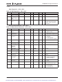
Table 3-7: Power and Motor Cable Stripping Lengths
Product
3-4
Frame
Size
Power Wiring in Inches (mm)
Motor Wiring in Inches (mm)
A1
B1
C1
D1
A2
B2
C2
D2
hp
Voltage
3/4 – 3
1–5
230V
480V
FR4
0.59
(15)
1.38
(35)
0.39
(10)
0.79
(20)
0.28
(7)
1.97
(50)
0.28
(7)
1.38
(35)
5 – 7-1/2 230V
7-1/2 – 15 480V
FR5
0.79
(20)
1.57
(40)
0.39
(10)
1.18
(30)
0.79
(20)
2.36
(60)
0.39
(10)
1.57
(40)
10 – 15
20 – 30
2 – 25
230V
480V
575V
FR6
0.79
(20)
3.54
(90)
0.59
(15)
2.36
(60)
0.79
(20)
3.54
(90)
0.59
(15)
2.36
(60)
20 – 30
40 – 60
30 – 40
230V
480V
575V
FR7
0.98
(25)
4.72
(120)
0.98
(25)
4.72
(120)
0.98
(25)
4.72
(120)
0.98
(25)
4.72
(120)
75 – 125
50 – 75
480V
575V
FR8
1.10
(28)
9.45
(240)
1.10
(28)
9.45
(240)
1.10
(28)
9.45
(240)
1.10
(28)
9.45
(240)
150 – 200 480V
100 – 300 575V
FR9
1.10
(28)
11.61
(295)
1.10
(28)
11.61
(295)
1.10
(28)
11.61
(295)
1.10
(28)
11.61
(295)
For more information visit: www.eatonelectrical.com
MN04003002E
For Sales and Support, Contact Walker EMD • Toll-free: (800) 876-4444 • Tel: (203) 426-7700 • Fax: (203) 426-7800 • www.walkeremd.com
SVX9000 AF Drive User Manual
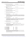
April 2004
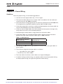
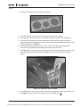
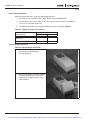
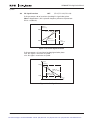
2. Locate the plastic bag containing the wiring plate.
Figure 3-2: Wiring Plate
3. If conduit is being used, attach the wiring plate to drive then conduit.
4. Pass the motor and input power wires/cables through the holes of the wiring plate.
5. Connect the input power and motor and control wires to their respective terminals
according to the wiring diagrams in the section marked “Standard Wiring Diagrams and
Terminal Locations” on Page 3-7.
6. If an optional external brake resistor is used, connect its cable to the appropriate
terminals. See “Standard Wiring Diagrams and Terminal Locations.”
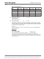
7. If shielded cable is used, connect the shields of the input line power cable and the motor
cable to the ground terminals of the SVX9000 drive, the motor and the line power
supply.
Figure 3-3: Ground Terminal Locations
8. If shielded cable is not used, check the connection of the ground cable to the motor, the
SVX9000 drive and the input line power terminals marked with
.
MN04003002E
For more information visit: www.eatonelectrical.com
For Sales and Support, Contact Walker EMD • Toll-free: (800) 876-4444 • Tel: (203) 426-7700 • Fax: (203) 426-7800 • www.walkeremd.com
3-5
SVX9000 AF Drive User Manual
April 2004
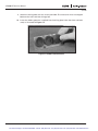
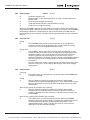
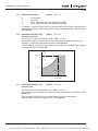
9. Attach the wiring plate with the screws provided. Ensure that no wires are trapped
between the frame and the wiring plate.
10. Insert the rubber grommets supplied into the wiring plate holes that have not been
used, as illustrated in Figure 3-4.
Figure 3-4: Cable Protection Plate
3-6
For more information visit: www.eatonelectrical.com
MN04003002E
For Sales and Support, Contact Walker EMD • Toll-free: (800) 876-4444 • Tel: (203) 426-7700 • Fax: (203) 426-7800 • www.walkeremd.com
SVX9000 AF Drive User Manual
April 2004
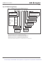
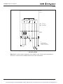
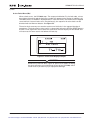
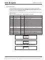
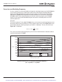
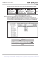
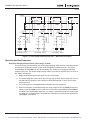
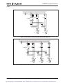
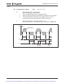
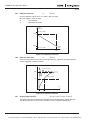
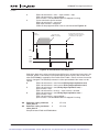
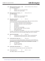
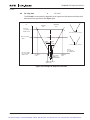
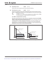
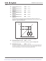
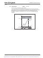
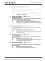
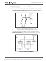
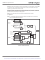
Standard Wiring Diagrams and Terminal Locations
The following wiring diagrams show the line and motor connections of the frequency
converter.
Power
Board
230V
480V
575V
3/4 - 15 hp
1 - 30 hp
2 - 25 hp
Control
Board
L1
L2
L3
R- U
V
W
DC- DC+/
R+
Note:
Integrated Brake
Chopper Circuit Not
Included on 575V units.
BR
Option
L1 L2 L3
See
Note
M
3~
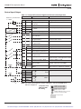
Figure 3-5: Principle Wiring Diagram of SVX Power Unit,
FR4 to FR5 and FR6
Note: When using a 1-phase supply, for units rated for such, connect the input power to
terminals L1 and L2. Consult Eaton Electrical for more information.
MN04003002E
For more information visit: www.eatonelectrical.com
For Sales and Support, Contact Walker EMD • Toll-free: (800) 876-4444 • Tel: (203) 426-7700 • Fax: (203) 426-7800 • www.walkeremd.com
3-7
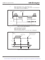
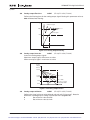
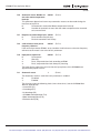
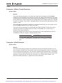
SVX9000 AF Drive User Manual
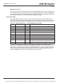
April 2004
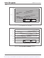
Power
Board
230V
480V
575V
20 - 30 hp
40 - 125 hp
30 - 75 hp
Control
Board
RFI Filter
L1
L2
L3
DC+/
R+
R- U
V
W
DCBR
Option
L1 L2 L3
See
Note
Note:
Integrated Brake
Chopper Circuit Not
Included on 575V units.
M
3~
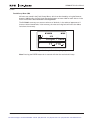
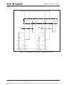
Figure 3-6: Principle Wiring Diagram of SVX Power Unit,
FR6, FR7 and FR8
Note: When using a 1-phase supply, for units rated for such, connect the input power to
terminals L1 and L2. Consult Eaton Electrical for more information.
3-8
For more information visit: www.eatonelectrical.com
MN04003002E
For Sales and Support, Contact Walker EMD • Toll-free: (800) 876-4444 • Tel: (203) 426-7700 • Fax: (203) 426-7800 • www.walkeremd.com
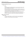
SVX9000 AF Drive User Manual
April 2004
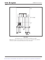
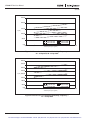
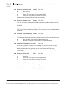
Power
Board
480V
575V
150 - 350 hp
100 - 300 hp
Control
Board
RFI Filter
L1
L2
L3
DC+/
R+
R- U
V
W
DCBR
Option
L1 L2
See
Note
L3
M
3~
Figure 3-7: Principle Wiring Diagram of SVX Power Unit,
FR9 to FR10
The dotted lines refer to components present in FR9 but not in FR10.
Note: When using a 1-phase supply, for units rated for such, connect the input power to
terminals L1 and L2. Consult Eaton Electrical for more information.
MN04003002E
For more information visit: www.eatonelectrical.com
For Sales and Support, Contact Walker EMD • Toll-free: (800) 876-4444 • Tel: (203) 426-7700 • Fax: (203) 426-7800 • www.walkeremd.com
3-9
SVX9000 AF Drive User Manual
April 2004
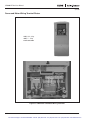
Power and Motor Wiring Terminal Photos
230V, 3/4 – 3 hp
480V, 1 – 5 hp
Frame Size: FR4
Figure 3-8: FR4 Power and Motor Wiring Terminals
3-10
For more information visit: www.eatonelectrical.com
MN04003002E
For Sales and Support, Contact Walker EMD • Toll-free: (800) 876-4444 • Tel: (203) 426-7700 • Fax: (203) 426-7800 • www.walkeremd.com
SVX9000 AF Drive User Manual
April 2004
230V, 5 – 7-1/2 hp
480V, 7-1/2 – 15 hp
Frame Size: FR5
Figure 3-9: FR5 Power and Motor Wiring Terminals
MN04003002E
For more information visit: www.eatonelectrical.com
3-11
For Sales and Support, Contact Walker EMD • Toll-free: (800) 876-4444 • Tel: (203) 426-7700 • Fax: (203) 426-7800 • www.walkeremd.com
SVX9000 AF Drive User Manual
April 2004
230V, 10 – 15 hp
480V, 20 – 30 hp
575V, 2 – 25 hp
Frame Size: FR6
Figure 3-10: FR6 Power and Motor Wiring Terminals
3-12
For more information visit: www.eatonelectrical.com
MN04003002E
For Sales and Support, Contact Walker EMD • Toll-free: (800) 876-4444 • Tel: (203) 426-7700 • Fax: (203) 426-7800 • www.walkeremd.com
SVX9000 AF Drive User Manual
April 2004
230V, 20 – 30 hp
480V, 40 – 60 hp
575V, 30 – 40 hp
Frame Size: FR7
Figure 3-11: FR7 Power and Motor Wiring Terminals
MN04003002E
For more information visit: www.eatonelectrical.com
3-13
For Sales and Support, Contact Walker EMD • Toll-free: (800) 876-4444 • Tel: (203) 426-7700 • Fax: (203) 426-7800 • www.walkeremd.com
SVX9000 AF Drive User Manual
April 2004
Supplied only when
Brake Chopper
included with Drive.
{
480V, 75 – 125 hp
575V, 50 – 75 hp
Frame Size: FR8
Figure 3-12: FR8 Power and Motor Wiring Terminals
3-14
For more information visit: www.eatonelectrical.com
MN04003002E
For Sales and Support, Contact Walker EMD • Toll-free: (800) 876-4444 • Tel: (203) 426-7700 • Fax: (203) 426-7800 • www.walkeremd.com
SVX9000 AF Drive User Manual
April 2004
480V, 150 – 200 hp
575V, 100 – 175 hp
Frame Size: FR9
Figure 3-13: FR9 Power and Motor Wiring Terminals
MN04003002E
For more information visit: www.eatonelectrical.com
3-15
For Sales and Support, Contact Walker EMD • Toll-free: (800) 876-4444 • Tel: (203) 426-7700 • Fax: (203) 426-7800 • www.walkeremd.com
SVX9000 AF Drive User Manual
April 2004
Checking the Cable and Motor Insulation
1. Check the motor cable insulation as follows:
●
Disconnect the motor cable from terminals U, V and W of the SVX9000 and from the
motor.
●
Measure the insulation resistance of the motor cable between each phase conductor as
well as between each phase conductor and the protective ground conductor.
●
The insulation resistance must be >1 MΩ.
2. Check the input power cable insulation as follows:
●
Disconnect the input power cable from terminals L1, L2 and L3 of the SVX9000 and
from the utility line feeder.
●
Measure the insulation resistance of the input power cable between each phase
conductor as well as between each phase conductor and the protective ground
conductor.
●
The insulation resistance must be >1 MΩ.
3. Check the motor insulation as follows:
3-16
●
Disconnect the motor cable from the motor and open any bridging connections in the
motor connection box.
●
Measure the insulation resistance of each motor winding. The measurement voltage
must equal at least the motor nominal voltage but not exceed 1000V.
●
The insulation resistance must be >1 MΩ.
For more information visit: www.eatonelectrical.com
MN04003002E
For Sales and Support, Contact Walker EMD • Toll-free: (800) 876-4444 • Tel: (203) 426-7700 • Fax: (203) 426-7800 • www.walkeremd.com
SVX9000 AF Drive User Manual
April 2004
Chapter 4 — Control Wiring
General Information
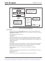
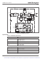
The control unit of the SVX9000 consists of the control board and various option boards that
plug into the five slot connectors (A to E) of the control board.
Galvanic isolation of the control terminals is provided as follows:
●
The control connections are isolated from power, and the GND terminals are
permanently connected to ground.
●
The digital inputs are galvanically isolated from the I/O ground.
●
The relay outputs are double-isolated from each other at 300V AC.
Option Board General Information
The SVX9000 series drives can accommodate a wide selection of expander and adapter
option boards to customize the drive for your application needs.
The drive’s control unit is designed to accept a total of five option boards. Option boards are
available for normal analog and digital inputs and outputs, communication and additional
application-specific hardware.
The SVX9000 factory installed standard option board configuration includes an A9 I/O board
and an A2 relay output board, which are installed in slots A and B. For information on
additional option boards, see the 9000X Series Drives Option Board User Manual.
B
C
D
E
A
Figure 4-1: Option Board Slots
MN04003002E
For more information visit: www.eatonelectrical.com
For Sales and Support, Contact Walker EMD • Toll-free: (800) 876-4444 • Tel: (203) 426-7700 • Fax: (203) 426-7800 • www.walkeremd.com
4-1
SVX9000 AF Drive User Manual
April 2004
Control Wiring Guidelines
Wire the control terminals using the following guidelines:
●
The control wires shall be at least AWG 20 (0.5 mm2) shielded cables.
●
The maximum wire size is AWG 14 (2.5 mm2) for the relay terminals and AWG 16
(1.5 mm2) for all other terminals.
●
The tightening torques for the option board terminals are listed in Table 4-1.
Table 4-1: Tightening Torques of Terminals
Tightening Torque
Terminal Screw
in-lbs
Nm
Relay and thermistor terminals
(M3 screw)
4.5
0.5
Other terminals (M2.6 screw)
2.2
0.25
Control Wiring Instructions
Table 4-2: Control Wiring Instructions
1. Unlock the bottom cover by turning
the locking screw 90 degrees
counterclockwise.
2. Remove the bottom cover by rotating
the cover towards you on the base
hinges, then lifting the cover away
from the base.
4-2
For more information visit: www.eatonelectrical.com
MN04003002E
For Sales and Support, Contact Walker EMD • Toll-free: (800) 876-4444 • Tel: (203) 426-7700 • Fax: (203) 426-7800 • www.walkeremd.com
SVX9000 AF Drive User Manual
April 2004
Table 4-2: Control Wiring Instructions (Continued)
3. Wire the control terminals following
the details for the specific option
boards shown on the following pages.
Note: Note for ease of access, the option
board terminal blocks can be
unplugged for wiring.
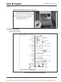
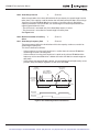
Control Wiring Details
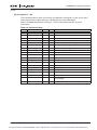
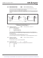
Wiring Option Board A9
Basic I/O Board A9
+10Vref
1
AI1+
2
GND
3
AI2+
4
AI2-
5
24Vout
6
GND
7
DIN1
8
DIN2
9
DIN3
10
CMA
11
Input Reference
(Voltage)
Input Reference
(Current)
Control Voltage Output
24V
GND
24Vout 12
GND
13
DIN4
14
DIN5
15
DIN6
16
CMB
17
AO1+
18
0 (4)/20 mA
AO1-
19
RL<500 Ω
DO1
20
+ V<+48V
I<50 mA
24V
GND
Indicates Connections for Inverted Signals
Figure 4-2: Option Board A9 Wiring Diagram
MN04003002E
For more information visit: www.eatonelectrical.com
For Sales and Support, Contact Walker EMD • Toll-free: (800) 876-4444 • Tel: (203) 426-7700 • Fax: (203) 426-7800 • www.walkeremd.com
4-3
SVX9000 AF Drive User Manual
April 2004
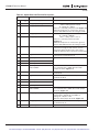
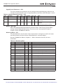
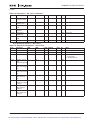
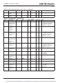
Table 4-3: Option Board A9 Terminal Descriptions
4-4
Terminal
Signal
Description and Parameter Reference
1
+10 Vref
Reference voltage
Maximum current 10 mA
2
AI1+
Analog input, voltage
3
GND
Analog input common
Default: 0 – +10V (Ri = 200 kΩ)
-10V to +10V (joystick control)
0 – 20 mA (Ri = 250 Ω)
Select V or mA with jumper block X1 (Figure 4-3)
Differential input if not connected to ground;
allows ±20V differential mode voltage to GND
4
AI2+
Analog input
5
GND/AI2- Analog input common
6
24 Vout
24V control voltage (bi-directional)
±15%, 250 mA (all boards total); 150 mA (max.
current from single board); Can be used as
external power backup for the control (and
fieldbus); Galvanically connected to terminal #12
7
GND
I/O ground
Ground for reference and controls; Galvanically
connected to terminals #13, 19
Ri = min. 5 kΩ
Default: 0 – 20 mA (Ri = 250 Ω)
0 – +10V (Ri = 200 kΩ)
-10V to +10V (joystick control)
Select V or mA with jumper block X2
(Figure 4-3)
Differential input if not connected to ground;
allows ±20V differential mode voltage to GND
8
DIA1
Digital input 1
9
DIA2
Digital input 2
10
DIA3
Digital input 3
11
CMA
Digital input common A for DIN1,
DIN2 and DIN3
Must be connected to GND or 24V of I/O terminal
or to external 24V or GND. Selection with
jumper block X3. (Figure 4-3)
12
24 Vout
24V control voltage (bi-directional)
Same as terminal #6; Galvanically connected to
terminal #6
13
GND
I/O ground
Same as terminal #7; Galvanically connected to
terminals #7 & 19
14
DIB4
Digital input 4
Ri = min. 5 kΩ
15
DIB5
Digital input 5
16
DIB6
Digital input 6
17
CMB
Digital input common B for DIN4,
DIN5 and DIN6
Must be connected to GND or 24V of I/O terminal
or to external 24V or GND. Select with jumper
block X3. (Figure 4-3)
18
A01+
Analog signal (+output)
Output signal range: 0 – 10V default
Current: 0(4) – 20 mA, RL max 500 Ω or
Voltage: 0 – 10V, RL >1 kΩ
Selection with jumper block X6. (Figure 4-3)
19
A01-
Analog output common
Maximum Vin = 48V DC; Galvanically connected
to terminals #7, 13
20
DO1
Digital output1
Open collector, Maximum current = 50 mA
For more information visit: www.eatonelectrical.com
MN04003002E
For Sales and Support, Contact Walker EMD • Toll-free: (800) 876-4444 • Tel: (203) 426-7700 • Fax: (203) 426-7800 • www.walkeremd.com
SVX9000 AF Drive User Manual
April 2004
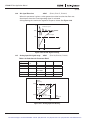
X2 Jumper Setting
Analog Input 2 (AI2)
X1 Jumper Setting
Analog Input 1 (AI1)
0 to 20 mA* A B C D
Current Input
ABC D
0 to 10V*
Voltage Input
ABC D
0 to 10V
Voltage Input
ABC D
0 to 20 mA
Current Input
0 to 10V
ABC D
(Differential)
Voltage Input
0 to 10V
ABC D
(Differential)
Voltage Input
X6 Jumper Setting
Analog Output 1 (A01)
ABC D
0 to 20 mA
Current Output
ABC D
-10 to 10V
Voltage Input
ABC D
0 to 10V*
Voltage Output
ABC D
-10 to 10V
Voltage Input
ABC D ABC D
X1
X2
ABC D
X6
X3 Jumper Setting
CMA and CMB Grounding
CMB Connected to Ground*
CMA Connected to Ground
X3
CMB Isolated from Ground
CMA Isolated from Ground
CMB and CMA Internally
Connected and Isolated
from Ground
* Designates Default Jumper Settings
Figure 4-3: Option Board A9 Jumper Location and Settings
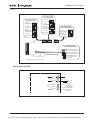
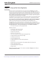
Wiring Option Board A2
Basic Relay Board A2
RO1/1
21
RO1/2
22
RO1/3
23
RO2/1
24
RO2/2
25
RO2/3
26
RL
AC / DC
Switching:
<8A / 24V DC
<0.4A / 125V DC
<8A / 250V AC
Continuously
<2 Arms
Figure 4-4: Option Board A2 Wiring Diagram
MN04003002E
For more information visit: www.eatonelectrical.com
For Sales and Support, Contact Walker EMD • Toll-free: (800) 876-4444 • Tel: (203) 426-7700 • Fax: (203) 426-7800 • www.walkeremd.com
4-5
SVX9000 AF Drive User Manual
April 2004
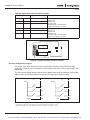
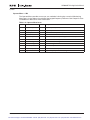
Table 4-4: Option Board A2 Terminal Descriptions
Terminal
Signal
Technical Information
Switching Capacity:
24V DC / 8A
250V AC / 8A
125V DC / 0.4A
Min Switching Load: 5V/10 mA
Continuous Capacity: <2 Arms
21
RO1/1
Normally Closed (NC)
22
RO1/2
Common
23
RO1/3
Normally Open (NO)
24
RO2/1
Normally Closed (NC)
25
RO2/2
Common
26
RO2/3
Normally Open (NO)
Switching Capacity:
24V DC / 8A
250V AC / 8A
125V DC / 0.4A
Min Switching Load: 5V/10 mA
Continuous Capacity: <2 Arms
21 22 23
24 25 26
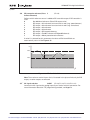
Figure 4-5: Option Board A2 Terminal Locations
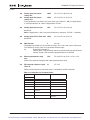
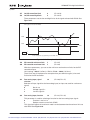
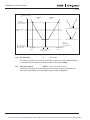
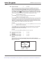
Inverting the Digital Input Signal
The active signal level depends on which potential the common inputs CMA and CMB
(terminals 11 and 17) are connected to. The alternatives are either +24V or ground (0V). See
Figure 4-6.
The 24V control voltage and the ground for the digital inputs and the common inputs (CMA,
CMB) can be sourced from either the internal 24V supply or an external supply.
1
2
+24V
Ground
Ground
DIN1
DIN1
DIN2
DIN2
DIN3
DIN3
CMA
+24V
CMA
Figure 4-6: Positive/Negative Logic
4-6
Positive logic (+24V is the active signal) = the input is active when the switch is closed.
Negative logic (0V is the active signal) = the input is active when the switch is closed.
For more information visit: www.eatonelectrical.com
MN04003002E
For Sales and Support, Contact Walker EMD • Toll-free: (800) 876-4444 • Tel: (203) 426-7700 • Fax: (203) 426-7800 • www.walkeremd.com
SVX9000 AF Drive User Manual
April 2004
Chapter 5 — Menu Information
Keypad Operation
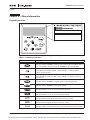
Figure 5-1: Keypad and Display
Table 5-1: LCD Status Indicators
Indicator
Description
Run
Indicates that the SVX9000 is running and controlling the load. Blinks when a
stop command has been given but the SVX9000 is still ramping down.
Counterclockwise Operation
The output phase rotation is BAC, corresponding to counterclockwise
rotation of most motors.
Clockwise Operation
The output phase rotation is ABC, corresponding to clockwise rotation of
most motors.
Stop
Indicates that the SVX9000 is stopped and not controlling the load.
Ready
Indicates that the SVX9000 is ready to be started.
Alarm
Indicates that there is one or more active drive alarm(s).
Fault
Indicates that there is one or more active drive fault(s).
I/O Terminal
Indicates that the I/O terminals have been chosen for control.
Keypad
Indicates that the keypad has been chosen for control.
Bus/Communications
Indicates that the communications bus control has been chosen for control.
MN04003002E
For more information visit: www.eatonelectrical.com
For Sales and Support, Contact Walker EMD • Toll-free: (800) 876-4444 • Tel: (203) 426-7700 • Fax: (203) 426-7800 • www.walkeremd.com
5-1
SVX9000 AF Drive User Manual
April 2004
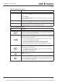
Table 5-2: LED Status Indicators
Indicator
Description
local
Local — Steady Illumination
Indicates that the SVX9000 is ready to be started and operated from the Local
mode.
Local — Flashing
Indicates that the SVX9000 is ready for operating command to select Local or
Remote operation.
remote
Remote
Indicates that the SVX9000 is operating and controlling the load remotely.
fault
Fault
Indicates that there is one or more active drive fault(s).
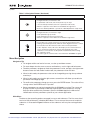
Table 5-3: Navigation Buttons
Button
Description
Start
This button operates as the START button for normal operation when the
“Keypad” is selected as the active control.
Enter
This button is used in the parameter edit mode to save the parameter setting
and move to the next parameter …
• to reset the Fault History if pressed while in the “Fault History” menu.
• to confirm the acceptance of a change.
• to change a virtual button status while in the “Button” menu.
• to confirm the start-up list at the end of the Start-Up Wizard.
• when the “Operate” menu is active, to exit the “Operate” submenu.
Stop
This button has two integrated operations. The button operates as STOP
button during normal operation …
• motor STOP from the keypad, which is always active unless disabled by
the “StopButtonActive” parameter.
• used to reset the active faults.
Reset
Resets the active faults.
Local / Remote
Switches between LOCAL and REMOTE control for start, speed reference and
reverse functions. The control locations corresponding to local and remote
can be selected within an application.
5-2
For more information visit: www.eatonelectrical.com
MN04003002E
For Sales and Support, Contact Walker EMD • Toll-free: (800) 876-4444 • Tel: (203) 426-7700 • Fax: (203) 426-7800 • www.walkeremd.com
SVX9000 AF Drive User Manual
April 2004
Table 5-3: Navigation Buttons (Continued)
Button
Description
Left Arrow
• navigation button, movement to left.
• in parameter edit mode, exits mode, backs up one step.
• cancels edited parameter (exit from a parameter edit mode).
• When in “Operate” menu will move backward through menu.
• At end of “Start-Up Wizard”, repeats the “Start-Up Wizard” setup menu.
Right Arrow
• navigation button, movement to right.
• enter parameter group mode.
• enter parameter mode from group mode.
• When in “Operate” menu will move forward through menu.
Up and Down Arrows
• move either up or down a menu list to select the desired menu item.
• editing a parameter/password, while the active digit/character is scrolled.
• increase/decrease the reference value of the selected parameter.
• in the “Operate” menu, will cause the display of the current reference
source and value and allow its change if the keypad is the active
reference source. Used to set the password (if defined) when leaving
the “Operate” menu.
• scroll through the “Active Faults” menu when the SVX9000 is stopped.
Menu Navigation
Navigation Tips
●
To navigate within one level of a menu, use the up and down arrows.
●
To move deeper into the menu structure and back out, use the right and left arrows.
●
To edit a parameter, navigate to show that parameter’s value, and press the right arrow
button to enter the edit mode. In edit mode, the parameter value will flash.
●
When in edit mode, the parameter value can be changed by pressing the up or down
arrow keys.
●
When in edit mode, pressing the right arrow a second time will allow you to edit the
parameter value digit by digit.
●
To confirm the parameter change you must press the ENTER button. The value will not
change unless the ENTER button is pushed.
●
Some parameters can not be changed while the SVX9000 is running. The screen will
display LOCKED if you attempt to edit these parameters while the drive is running.
Stop the drive to edit these parameters. See the SVX9000 Application Manual for
identification of these parameters specific to your chosen application.
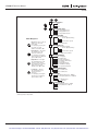
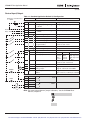
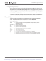
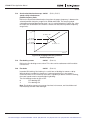
Main Menu
The data on the control keypad are arranged in menus and submenus. The first menu level
consists of M1 to M8 and is called the Main Menu. The structure of these menus and their
submenus is illustrated in Figure 5-2. Some of the submenus will vary for each application
choice.
MN04003002E
For more information visit: www.eatonelectrical.com
For Sales and Support, Contact Walker EMD • Toll-free: (800) 876-4444 • Tel: (203) 426-7700 • Fax: (203) 426-7800 • www.walkeremd.com
5-3
SVX9000 AF Drive User Manual
April 2004
+ M1 Parameters
G1.1
...
G1.x
+ M2 Keypad Control
R2.1 Keypad Reference
P2.2 Keypad Direction
...
P2.x Stop Button Active
+ M3 Active Faults
Menu Navigation:
Up Arrow — The up arrow
advances to the next
menu item.
For example, pressing the
up arrow once will
advance from M1 to M2.
Down Arrow — The down
arrow backs up to the
previous menu item.
For example, pressing the
down arrow once will back
up from M2 to M1.
Right Arrow — The right
arrow will advance to the
next level in the menu.
For example, pressing the
right arrow once will
advance from M2 to R2.1.
Left Arrow — The left
arrow will back up one
level in the menu
structure.
For example, pressing the
left arrow once will back
up from R2.1 to M2.
A3.1 Active Fault 1
T3.1.1 Operation Days
...
T3.1.13 Zero Speed
...
A3.x Active Fault x
+ M4 Fault History
H4.1 Most Recent Fault
T4.1.1 Operation Days
...
T4.1.13 Zero Speed
...
H4.1.x Oldest Saved Fault
+ M5 System Menu
S5.1
S5.2
S5.3
S5.4
S5.5
S5.6
S5.7
S5.8
Language
Application
Copy Parameters
Compare Parameters
Security
Keypad Settings
Hardware Settings
System Information
+ M6 Expander Boards
G6.1 Slot A Board
...
G6.5 Slot E Board
+ M7 Monitor
V7.1 Output Frequency - 0.00 Hz
V7.2 Frequency Reference - 0.00 Hz
...
M7.1x Multimonitor
N7.1x.1
+ M8 Operate Mode
O1 Output Frequency - 0.0 Hz
O2 Freq Reference - 0.0 Hz
...
Ox . . .
Figure 5-2: Main Menu Navigation
5-4
Menu application dependent.
For more information visit: www.eatonelectrical.com
MN04003002E
For Sales and Support, Contact Walker EMD • Toll-free: (800) 876-4444 • Tel: (203) 426-7700 • Fax: (203) 426-7800 • www.walkeremd.com
SVX9000 AF Drive User Manual
April 2004
Parameter Menu (M1)
The Parameter Menu is a single or multi-level menu dependent upon the application in use,
arranged by the parameter group items. Figure 5-3 illustrates this for the Standard
application. Parameters and parameter groups are explained in further detail in the SVX9000
Application Manual.
M1 Parameters Menu
+ G1.1 Basic Parameters
P1.1.1 Minimum Frequency
P1.1.2 Maximum Frequency
...
P1.1.16 Preset Speed 1
+ G1.2 Input Signals
P1.2.1 Start/Stop Logic
P1.2.2 DIN3 Function
...
P1.2.9 AI2 Signal Select
+ G1.3 Output Signals
P1.3.1 A1out Signal
P1.3.2 A1out Content
...
P1.3.17 A2out Scale
+ G1.4 Drive Control
P1.4.1 Ramp 1 Shape
P1.4.2 Ramp 2 Shape
...
P1.4.13 Flux Brake Current
+ G1.5 Skip Frequency
P1.5.1 Skip F1 Low Limit
P1.5.2 Skip F1 High Limit
P1.5.3 PH Accel/Decel Ramp
+ G1.6 Motor Control
P1.6.1 Motor Control Mode
P1.6.2 V/Hz Optimization
...
P1.6.13 Identification
+ G1.7 Protections
P1.7.1 4mA Input Fault
P1.7.2 4mA Fault Frequency
...
P1.7.23 Slot Comm Fault Response
+ G1.8 Auto Restart
P1.8.1 Wait Time
P1.8.2 Trial Time
...
P1.8.10 Underload Tries
Figure 5-3: Parameter Menu Structure Example
MN04003002E
For more information visit: www.eatonelectrical.com
For Sales and Support, Contact Walker EMD • Toll-free: (800) 876-4444 • Tel: (203) 426-7700 • Fax: (203) 426-7800 • www.walkeremd.com
5-5
SVX9000 AF Drive User Manual
April 2004
Keypad Control Menu (M2)
In the Keypad Control Menu, you can set the frequency reference, choose the motor
direction for keypad operation, and determine if the STOP button will be active at all
times. See Figure 5-4.
M2 Keypad Control
R2.1 Keypad Reference
P2.2 Keypad Direction
...
P2.x Stop Button Active
Figure 5-4: Keypad Control Menu
5-6
R2.1
Keypad
Reference
Range: Min. Frequency — Max. Frequency
Units: Hertz
Keypad Reference
This displays and allows the operator to edit the keypad frequency reference. A
change takes place immediately. This reference value will not influence the output
frequency unless the keypad has been selected as the active control place.
P2.2
Keypad
Direction
Range: Forward, Reverse
Default: Forward
Keypad Direction
This allows the operator to change the rotation direction of the motor. This setting
will not influence the rotation direction of the motor unless the keypad has been
selected as the active control place.
P2.3 Stop Button
Active
Range: Yes, No
Default: Yes
StopButtonActive
By default, pushing the STOP button will always stop the motor regardless of the
selected control place. If this parameter is set to No, the STOP button will stop the
motor only when the keypad has been selected as the active control place.
This parameter number varies for different applications.
For more information visit: www.eatonelectrical.com
MN04003002E
For Sales and Support, Contact Walker EMD • Toll-free: (800) 876-4444 • Tel: (203) 426-7700 • Fax: (203) 426-7800 • www.walkeremd.com
SVX9000 AF Drive User Manual
April 2004
Active Faults Menu (M3)
When a fault occurs, the SVX9000 stops. The sequence indication F1, the fault code, a short
description of the fault and the fault type symbol will appear on the display. In addition, the
indication FAULT or ALARM is displayed and, in case of a FAULT, the red LED on the keypad
starts to blink. If several faults occur simultaneously, the sequence of active faults can be
browsed with the Browser buttons. See Figure 5-5.
The active faults memory can store the maximum of 10 faults in the sequential order of
appearance. The fault remains active until it is cleared with either the STOP or RESET buttons
or with a reset signal from the I/O terminal. Upon fault reset the display will be cleared and
will return to the same state it was before the fault trip.
51
F
Ext Fault
T1
T13
Figure 5-5: Active Fault Display Example
CAUTION
Remove any External Start signals or permissives before resetting
the fault to prevent an unintentional restart of the SVX9000, which
could result in personal injury or equipment damage.
MN04003002E
For more information visit: www.eatonelectrical.com
For Sales and Support, Contact Walker EMD • Toll-free: (800) 876-4444 • Tel: (203) 426-7700 • Fax: (203) 426-7800 • www.walkeremd.com
5-7
SVX9000 AF Drive User Manual
April 2004
Fault Type
Range: A, F, AR, FT
Fault Type
There are four different types of faults. These faults and their definitions are given in
Table 5-4.
Table 5-4: Fault Types
Fault Code
Fault Time
Data Record
Fault
Type
Fault Name
Description
A
Alarm
This type of fault is a sign of an unusual operating
condition. It does not cause the drive to stop, nor does it
require any special actions. The “A fault” remains in the
display for about 30 seconds.
F
Fault
An “F fault” is a kind of fault that makes the drive stop.
Actions need to be taken in order to restart the drive.
AR
Auto-Restart
Fault
If an “AR fault” occurs the drive will also stop
immediately. The fault is reset automatically and the drive
tries to restart the motor. If the restart is not successful, a
fault trip (FT) occurs.
FT
Fault Trip
If the drive is unable to restart the motor after an AR fault,
an FT fault occurs. The effect of the “FT fault” is the same
as that of the F fault — the drive is stopped.
Range: 1 – 54
Fault codes indicate the cause of the fault. A list of fault codes, their descriptions,
and possible solutions can be found in Appendix B — Fault and Warning Codes.
Range: T.1 – T.13
In this menu, important data recorded at the time the fault is available. This feature
is intended to help the user or the service person to determine the cause of fault.
Table 5-5 indicates the information that is recorded.
Table 5-5: Fault Time Data
Data
Units
Description
D
Counted operation days (Fault 43: Additional code)
hh:mm:ss
(d)
Counted operation hours
(Fault 43: Counted operation days)
T.3
Hz
hh:mm:ss
Output frequency
(Fault 43: Counted operation hours)
T.4
T.5
T.6
T.7
T.8
A
V
%
%
V
Motor current
Motor voltage
Motor power
Motor torque
DC bus voltage
T.9
T.10
T.11
T.12
T.13
°C
—
—
—
—
Unit temperature
Run status
Direction
Warnings
Zero speed
T.1 T.2
Real time record.
If real time is set, T.1 and T.2 will appear as follows:
5-8
T.1
yyyy-mm-dd
Counted operation days (Fault 43: Additional code)
T.2
hh:mm:ss.sss
Counted operation hours (Fault 43: Counted operation days)
For more information visit: www.eatonelectrical.com
MN04003002E
For Sales and Support, Contact Walker EMD • Toll-free: (800) 876-4444 • Tel: (203) 426-7700 • Fax: (203) 426-7800 • www.walkeremd.com
SVX9000 AF Drive User Manual
April 2004
Fault History Menu (M4)
All faults are stored in the Fault History Menu, which can be viewed by using the Browser
buttons. Additionally, the Fault time data record pages are accessible for each fault as in the
Active Faults Menu described above. See Figure 5-6.
The SVX9000’s memory can store a maximum of 30 faults, in the order of appearance. If
there are 30 uncleared faults in the memory, the next occurring fault will erase the oldest
fault from the memory.
11
F
Output Phase
T1
T13
Figure 5-6: Sample Fault History Display
Note: Pressing the ENTER button for 3 seconds will clear the entire fault history.
MN04003002E
For more information visit: www.eatonelectrical.com
For Sales and Support, Contact Walker EMD • Toll-free: (800) 876-4444 • Tel: (203) 426-7700 • Fax: (203) 426-7800 • www.walkeremd.com
5-9
SVX9000 AF Drive User Manual
April 2004
System Menu (M5)
The controls associated with the general use of the drive, such as application selection,
customized parameter sets or information about the hardware and software are located in
the System Menu. Password protection can be activated by parameter S5.5.1.
Descriptions of the system menu parameters are illustrated in Figure 5-7.
+ S5.1 Language Selection
+ S5.2 Application Selection
+ S5.3 Copy Parameters
S5.3.1
S5.3.2
S5.3.3
S5.3.4
Parameter Sets
Upload to Keypad
Download from Keypad
Automate Backup
S5.4 Parameter Comparison
+ S5.5 Security
S5.5.1
P5.5.2
P5.5.3
P5.5.4
Password
Parameter Lock
Start-Up Wizard
Multimonitor Items
+ S5.6 Keypad Settings
P5.6.1
P5.6.2
P5.6.3
P5.6.4
P5.6.5
Default Page
Default Page/Operating Menu
Timeout Time
Contrast Adjustment
Backlight Time
+ S5.7 Hardware Settings
P5.7.1
P5.7.2
P5.7.3
P5.7.4
Internal Brake Resistor
Fan Control
HMI Acknowledge Timeout
HMI Number of Retries
+ S5.8 System Information
+
+
+
+
+
+
+
S5.8.1 Total Counters
C5.8.1.1 MWh Counter
C5.8.1.2 Power On Day Counter
C5.8.1.3 Power On Hour Counter
S5.8.2 Trip Counters
T5.8.2.1 MWh Counter
T5.8.2.2 Clear MWh Trip Counter
T5.8.2.3 Power On Day Counter
T5.8.2.4 Power On Hour Counter
T5.8.2.5 Clear Operating Time Counter
S5.8.3 Software Information
I5.8.3.1 Software Package
I5.8.3.2 System Software Version
I5.8.3.3 Firmware Interface
I5.8.3.4 System Load
S5.8.4 Applications
A5.8.4.# Name of Application
D5.8.4.#.1 Application ID
D5.8.4.#.2 Version
D5.8.4.#.3 Firmware Interface
S5.8.5 Hardware
I5.8.5.1 Nominal Unit Power
I5.8.5.2 Nominal Unit Voltage
E5.8.5.3 Brake Chopper
E5.8.5.4 Brake Resistor
S5.8.6 Expander Boards
S5.8.7 Debug Menu
Figure 5-7: System Menu Structure
5-10
For more information visit: www.eatonelectrical.com
MN04003002E
For Sales and Support, Contact Walker EMD • Toll-free: (800) 876-4444 • Tel: (203) 426-7700 • Fax: (203) 426-7800 • www.walkeremd.com
SVX9000 AF Drive User Manual
April 2004
System Menu Parameters
S5.1
Language
Selection
S5.2
Application
Selection
Range: English, Spanish, French, Portuguese
Default: English
Language
This parameter offers the ability to control the SVX9000 through the keypad in the
language of your choice. Available languages are: English, Spanish, French and
Portuguese.
Default: Basic
Application
This parameter sets the active application.
When changing applications, you will be asked if you want the parameters of the
new application to be uploaded to the keypad. If you wish to load the new
application parameters, push the ENTER button. Pushing any other button saves the
parameters of the previously used application in the keypad.
System Menu Copy Parameter Options (S5.3)
The parameter copy function is used when the operator wants to copy one or all parameter
groups from one drive to another. All the parameter groups are first uploaded to the keypad,
then the keypad is connected to another drive and then the parameter groups are
downloaded to it (or possibly back to the same drive).
Note: Before any parameters can successfully be copied from one drive to another, the drive
must be stopped when the parameters are downloaded to it.
S5.3.1
Parameter
Sets
S5.3.2
Upload to
Keypad
S5.3.3
Download
from Keypad
S5.3.4
Automatic
Backup
MN04003002E
Parameter Sets
This parameter allows you to reload the factory default parameter values, and to
store and load two customized parameter sets.
Up to keypad
This function uploads all existing parameter groups to the keypad.
Range: 0 – 3
Default: 0 (All parameters)
Down from keypad
This function downloads one or all parameter groups from the keypad to the drive.
0 All parameters
1 All, no motor
2 Application parameters
Range: Yes, No
Default: Yes
Auto.backup
This parameter activates and deactivates the parameter backup function. When the
Parameter backup function is activated, the keypad makes a copy of the parameters
and settings in the currently active application. When applications are changed, you
will be asked if you wish the parameters of the new application to be uploaded to
the keypad. For this to happen, push the ENTER button. If you wish to keep the copy
of the parameters of the previously used application saved in the keypad push any
other button.
Note: Parameters saved in the parameter settings of S5.3.1 will be deleted when
applications are changed. If you want to transfer the parameters from one
application to another you have to upload them to the keypad first.
For more information visit: www.eatonelectrical.com
5-11
For Sales and Support, Contact Walker EMD • Toll-free: (800) 876-4444 • Tel: (203) 426-7700 • Fax: (203) 426-7800 • www.walkeremd.com
SVX9000 AF Drive User Manual
April 2004
System Menu Parameter Comparison Options (S5.4)
S5.4
Parameter
Comparison
Parameter Comparison
With the Parameter Comparison function, you can compare the actual parameter
values to the values of your customized parameter sets and those loaded to the
control keypad.
The actual parameter values are first compared to those of the customized
parameter Set1. If no differences are detected, a “0” is displayed on the lowermost
line of the keypad.
If any of the parameter values differ from those of the Set1 parameters, the number of
the deviations is displayed together with symbol P (e.g. P1 P5 = five deviating values).
By pressing the right arrow button once again you will see both the actual value and
the value it was compared to. In this display, the value on the Description line (in the
middle) is the default value, and the one on the value line (lowermost line) is the
edited value. You can also edit the actual value by pushing the Right Arrow button.
Actual values can also be compared to Set2, Factory Settings and the Keypad Set values.
Security Menu Parameter Options (S5.5)
Note: The Security submenu is protected with a password. Store the password in a safe place.
5-12
S5.5.1
Password
Range: 0 – 65535
Default: 0
Password
The application selection can be protected against unauthorized changes with the
Password function. When the password function is enabled, the user will be
prompted to enter a password before application changes, parameter value
changes, or password changes.
By default, the password function is not in use. If you want to activate the password,
change the value of this parameter to any number between 1 and 65535. The
password will be activated after the Timeout time (Timeout Time) has expired.
To deactivate the password, reset the parameter value to 0.
P5.5.2
Parameter
Lock
Range: ChangeEnable, ChangeDisabl
Default: ChangeDisabl
Parameter Lock
This function allows the user to prohibit changes to the parameters. If the parameter
lock is activated the text *locked* will appear on the display if you try to edit a
parameter value.
Note: This function does not prevent unauthorized editing of parameter values.
P5.5.3
Start-Up
Wizard
Range: Yes, No
Default: No
Start-up Wizard
The Start-Up Wizard facilitates commissioning the SVX9000. If selected active, the
Start-Up Wizard prompts the operator for the language and application desired and
then advances through the start-up parameter list. After completion it allows the
user to repeat the Start-Up Wizard or return to the default page, the Operate Menu.
The Start-Up Wizard in always active for the initial power up of the SVX9000.
P5.5.4
Multimonitor
Items
Range: ChangeEnable, ChangeDisabl
Default: ChangeEnable
Multimon.items
The keypad display can display three actual monitored values at the same time. This
parameter determines if the operator is allowed to replace the values being
monitored with other values.
For more information visit: www.eatonelectrical.com
MN04003002E
For Sales and Support, Contact Walker EMD • Toll-free: (800) 876-4444 • Tel: (203) 426-7700 • Fax: (203) 426-7800 • www.walkeremd.com
SVX9000 AF Drive User Manual
April 2004
Keypad Settings (S5.6)
There are five parameters (Default Page to Backlight Time) associated with the keypad
operation:
P5.6.1
Default Page
P5.6.2
Default Page
in the
Operating
Menu
P5.6.3
Timeout Time
P5.6.4
Contrast
Adjustment
P5.6.5
Backlight
Time
MN04003002E
Default: 0
Default page
This parameter sets the view to which the display automatically moves as the
Timeout Time expires or when the keypad power is switched on. If the Default Page
value is 0 this function is not activated, i.e. the last displayed page remains on the
keypad display.
Default page/OM
Here you can set the location in the Operating menu to which the display
automatically moves as the set Timeout Time expires, or when the keypad power is
switched on. See setting of Default Page parameter above.
Range: 0 – 65,535
Default: 30
Units: Seconds
Timeout time
The Timeout Time setting defines the time after which the keypad display returns to
the Default Page.
Note: If the Default Page value is 0 the Timeout Time setting has no effect.
Contrast adjustment
If the display is not clear, you can adjust the keypad contrast with this parameter.
Range: 1 – 65,535 or Forever
Default: 10
Units: Minutes
Backlight time
This parameter determines how long the backlight stays on before going out. You
can select any time between 1 and 65,535 minutes or “Forever”.
For more information visit: www.eatonelectrical.com
5-13
For Sales and Support, Contact Walker EMD • Toll-free: (800) 876-4444 • Tel: (203) 426-7700 • Fax: (203) 426-7800 • www.walkeremd.com
SVX9000 AF Drive User Manual
April 2004
Hardware Settings (S5.7)
The Hardware Settings submenu (S5.7) provides parameters for setting information on
Internal brake resistor connection, Fan control, Keypad acknowledge timeout and Keypad
retries.
5-14
P5.7.1
Internal Brake
Resistor
Connection
Range: Connected – Not Connected
Default: Connected
Internbrakeres
With this function you tell the SVX9000 whether the internal brake resistor is
connected or not.
If your drive has an internal brake resistor, the default value of this parameter is
“Connected”. However, if it is necessary to increase braking capacity by installing an
external brake resistor, or if the internal brake resistor is disconnected, it is advisable
to change the value of this function to “Not Connected” in order to avoid
unnecessary fault trips.
Note: The brake resistor is available as an option for all drives. It can be installed
internally in frame sizes FR4 to FR6.
P5.7.2
Fan Control
Range: Continuous, Temperature
Default: Continuous
Fan control
This function sets the control method of the SVX9000’s cooling fan. You can set the
fan to run continuously when the power is switched on or to run based on the
temperature of the unit. If the latter function has been selected, the fan is switched
on automatically when the heatsink temperature reaches 60°C. The fan receives a
stop command when the heatsink temperature falls to 55°C. The fan runs for about a
minute after receiving the stop command or switching on the power, as well as after
changing the value from “Continuous” to “Temperature”.
Note: The fan runs continuously, regardless of this setting, when the SVX9000 is in
RUN state.
P5.7.3
Keypad
Acknowledge
Timeout
Range: 200 – 5,000
Default: 200
Units: mseconds
Keypad ACK timeout
This function allows the user to change the timeout of the Keypad
acknowledgement time.
Note: If the SVX9000 has been connected to a PC with a serial cable, the default
values of Keypad Acknowledge Timeout and Number of Retries to Receive Keypad
Acknowledgement must not be changed.
If the SVX9000 has been connected to a PC via a modem and there is delay in
transferring messages, the value of Keypad Acknowledge Timeout must be set
according to the delay as follows:
Example:
• Transfer delay between the SVX9000 and the PC is found to be = 600 ms
• The value of Keypad Acknowledge Timeout is set to 1200 ms (2 x 600, sending
delay + receiving delay)
• The corresponding setting is then entered in the [Misc] section of the file
9000XDrive.ini:
Retries = 5
AckTimeOut = 1200
TimeOut = 5000
It must also be considered that intervals shorter than the Keypad Acknowledge
Timeout time cannot be used in SVX9000 drive monitoring.
For more information visit: www.eatonelectrical.com
MN04003002E
For Sales and Support, Contact Walker EMD • Toll-free: (800) 876-4444 • Tel: (203) 426-7700 • Fax: (203) 426-7800 • www.walkeremd.com
SVX9000 AF Drive User Manual
April 2004
P5.7.4
Number of
Retries to
Receive
Keypad
Acknowledgement
Range: 1 – 10
Default: 5
Keypad retry
With this parameter you can set the number of times the drive will try to receive an
acknowledgement when it has not been received within the acknowledgement time
(Keypad Acknowledge Timeout) or if the received acknowledgement is faulty.
System Information (S5.8)
This section contains hardware and software information as well as operation information.
S5.8.1
Total
Counters
Total counters
In the Total Counters page you will find information related to the SVX9000
operating times, i.e. the total numbers of MWh, operating days and operating hours.
See Table 5-6.
Unlike the counters for the Trip Counters, these counters cannot be reset.
Note: The Power On time counters, days and hours, operate whenever power is
applied to the SVX9000.
Table 5-6: Total Counters
S5.8.2
Trip Counters
Number
Name
Description
C5.8.1.1
MWh counter
Megawatt hours total operation time counter
C5.8.1.2
Power On day
counter
Number of days the SVX9000 has been supplied
with power
C5.8.1.3
Power On hour Number of hours the SVX9000 has been supplied
counter
with power
Trip counters
The Trip Counters are counters whose values can be reset to zero. The resettable
counters are shown in Table 5-7.
Table 5-7: Trip Counters
Number
Name
Description
T5.8.2.1
MWh counter
Megawatts hours since last reset
P5.8.2.2
Clear MWh
counter
Resets megawatts hours counter
T5.8.2.3
Power On day
counter
Number of days the SVX9000 has been run since the
last reset
T5.8.2.4
Power On hour Number of hours the SVX9000 has been run since the
counter
last reset
P5.8.2.5
Clr Optime cntr Resets the operating day and hour counters
Note: The Trip Counters operate only when the motor is running.
MN04003002E
For more information visit: www.eatonelectrical.com
5-15
For Sales and Support, Contact Walker EMD • Toll-free: (800) 876-4444 • Tel: (203) 426-7700 • Fax: (203) 426-7800 • www.walkeremd.com
SVX9000 AF Drive User Manual
April 2004
S5.8.3
Software
Information
Software
The Software information page includes information on the following software
related topics:
Table 5-8: Software Information
S5.8.4
Application
Information
Number
Name
Description
I5.8.3.1
Software
package
SVX00031V003
I5.8.3.2
System
software
version
11.53.6536
I5.8.3.3
Firmware
interface
4.37
I5.8.3.4
System load
G9.1
Applications
The Application information page includes information on not only the application
currently in use but also all other applications loaded into the SVX9000. The
information available is shown in Table 5-9. Note that the “x” in the table refers to
the sequential number of the application in the list.
Table 5-9: Application Information
S5.8.5
Hardware
Information
Name
Content
A4.8.4.x
Application name
D4.8.4.x.1
Application ID
D4.8.4.x.2
Version
D4.8.4.x.3
Firmware interface
Hardware
The Hardware information page provides information on the following hardwarerelated topics:
Table 5-10: Hardware Information
5-16
Number
Content
I5.8.5.1
Nominal power of the unit
I5.8.5.2
Nominal voltage of the unit
E5.8.5.3
Brake chopper
E5.8.5.4
Brake resistor
For more information visit: www.eatonelectrical.com
MN04003002E
For Sales and Support, Contact Walker EMD • Toll-free: (800) 876-4444 • Tel: (203) 426-7700 • Fax: (203) 426-7800 • www.walkeremd.com
SVX9000 AF Drive User Manual
April 2004
S5.8.6
Expander
Board
Information
Expander boards
This parameter and its sub-items provide information about the basic and option
boards plugged into the control board as shown in Table 5-11. Note that the “x” in
the table refers to the sequential number of the slot, with slot A being “1” and slot
E being “5”.
Table 5-11: Expander Board Information
S5.8.7
Debug Menu
MN04003002E
Number
Content
E5.8.6.x
Slot “x” board identification
E5.8.6.x.1
Operating state
E5.8.6.x.2
Software version
Debug
This menu is meant for advanced users and application designers. Contact the
factory for any assistance needed.
For more information visit: www.eatonelectrical.com
5-17
For Sales and Support, Contact Walker EMD • Toll-free: (800) 876-4444 • Tel: (203) 426-7700 • Fax: (203) 426-7800 • www.walkeremd.com
SVX9000 AF Drive User Manual
April 2004
Expander Board Menu (M6)
The Expander Board Menu makes it possible for the user to:
●
to see what expander boards are connected to the control board and
●
to access and edit the parameters associated with the expander board.
+ G6.1 “A: OPTA9” (Slot A Option Board)
G6.1.1 Parameters
P6.1.1.1 AI1 Mode
P6.1.1.2 AI2 Mode
P6.1.1.3 AO1 Mode
G6.1.2 I/O-monitor
+
+
+
+
G6.2
G6.3
G6.4
G6.5
“B:
“C:
“D:
“E:
” (Slot B Option Board)
” (Slot C Option Board)
” (Slot D Option Board)
” (Slot E Option Board)
Figure 5-8: Expander Board Menu Structure
Example of Expander Board Parameters for Option Board A9
P6.1.1.1
AI1 Mode
Range: 1 – 5
AI1 Mode
Analog Input 1 input options:
1 0 – 20 mA
2 4 – 20 mA
3 0 – 10V
4 2 – 10V
5 -10 – +10VP
Default: 3
P6.1.1.2
AI2 Mode
Range: 1 – 5
AI2 Mode
Analog Input 2 input options:
1 0 – 20 mA
2 4 – 20 mA
3 0 – 10V
4 2 – 10V
5 -10 – +10VP
Default: 1
Range: 1 – 4
A01 Mode
Analog Output 1 output options:
1 0 – 20 mA
2 4 – 20 mA
3 0 – 10V
4 2 – 10V
Default: 1
P6.1.1.3
AO1 Mode
5-18
For more information visit: www.eatonelectrical.com
MN04003002E
For Sales and Support, Contact Walker EMD • Toll-free: (800) 876-4444 • Tel: (203) 426-7700 • Fax: (203) 426-7800 • www.walkeremd.com
SVX9000 AF Drive User Manual
April 2004
Monitoring Menu (M7)
The Monitoring Menu items are meant for viewing parameter values during operation.
Monitored values are updated every 0.3 sec. Monitored items are identified by item numbers
V7.1 to V1.xx, where “xx” varies by application. Table 5-12 provides an example of the
monitored values for the Standard application.
Monitored parameters are not editable from this menu (See Parameter Menu [M1] to change
parameter values).
Table 5-12: Monitoring Menu Items — Standard Application Example
Code
Signal Name
Unit
Description
V7.1
Output Frequency
Hz
Output frequency
V7.2
Frequency reference
Hz
Frequency reference setting
V7.3
Motor speed
rpm
Calculated motor speed
V7.4
Motor current
A
Measured motor current
V7.5
Motor torque
%
Calculated torque based on nominal motor torque
V7.6
Motor power
%
Calculated power based on nominal motor power
V7.7
Motor voltage
V
Calculated motor voltage
V7.8
DC bus voltage
V
Measured DC-bus voltage
V7.9
Unit temperature
°C
Heatsink temperature
V7.10
Calculated motor
temperature
°C
Calculated motor temperature based on the motor
nameplate information and the calculated motor load
V7.11
Analog Input 1
V
Voltage input at Terminals AI1+ and GND
V7.12
Analog Input 2
mA
Current input at Terminals AI2+ and AI2-
V7.13
DIN1, DIN2, DIN3
—
Digital input status (Figure 5-9)
V7.14
DIN4, DIN5,DIN6
—
Digital input status (Figure 5-10)
V7.15
DO1, RO2, RO3
—
Digital and relay output status (Figure 5-11)
V7.16
Analog Iout
mA
Current output at Terminals AO1+ and AO1-
V1.13
DIN1, DIN2, DIN3
OFF ON OFF
Figure 5-9: Digital Inputs — DIN1, DIN2, DIN3 Status
V1.14
DIN4, DIN5, DIN6
ON OFF OFF
Figure 5-10: Digital Inputs — DIN4, DIN5, DIN6 Status
V1.15
DO1, RO1, RO2
OFF OFF ON
Figure 5-11: Digital and Relay Outputs — DO1, RO1, RO2 Status
MN04003002E
For more information visit: www.eatonelectrical.com
5-19
For Sales and Support, Contact Walker EMD • Toll-free: (800) 876-4444 • Tel: (203) 426-7700 • Fax: (203) 426-7800 • www.walkeremd.com
SVX9000 AF Drive User Manual
April 2004
Multimonitor (V7.17)
This parameter allows the viewing and selection (if allowed by System menu item, P5.5.4) of
three simultaneously monitored items from the Monitored Menu Items shown in Table 5-12.
Use the right arrow key to select the item to be modified and then the up or down arrow keys
to select the new item. Press the ENTER key to accept the change.
Operate Menu (M8)
The Operate Menu provides a easy to use method of viewing key numerical Monitoring
Menu items. Some applications also support the setting of reference values in this menu. The
items displayed vary by application. Table 5-13 is an example for the Standard application.
Table 5-13: Operate Menu Items — Standard Application Example
Code
Signal Name
Unit
Description
O.1
Output Frequency
Hz
Output frequency
O.2
FreqReference
Hz
Frequency reference
O.3
Motor Speed
rpm
Calculated motor speed
O.4
Motor Current
A
Measured motor current
O.5
Motor Torque
%
Calculated torque based on nominal motor torque
O.6
Motor Power
%
Calculated power based on nominal motor power
O.7
Motor Voltage
V
Calculated motor voltage
O.8
DC-Bus Voltage
V
Measured DC-bus voltage
O.9
Unit Temperature
°C
Heatsink temperature
O.10
MotorTemperature
%
Calculated motor temperature based on the motor
nameplate information and the calculated motor load
R1
Keypad Reference
Hz
Keypad frequency reference setting
The menu is navigated by using the left and right arrow buttons. If a reference level is
available for setting, the up and down arrow buttons adjust the value. To exit the Operate
Menu to access the other menus, depress the ENTER button for 2 seconds. While in the other
menus, if there is no keypad activity, the display will return to the Operate Menu after 30
seconds. Figure 5-12 illustrates the Operate Menu button function.
5-20
For more information visit: www.eatonelectrical.com
MN04003002E
For Sales and Support, Contact Walker EMD • Toll-free: (800) 876-4444 • Tel: (203) 426-7700 • Fax: (203) 426-7800 • www.walkeremd.com
SVX9000 AF Drive User Manual
April 2004
One Touch Operate Menu
Navigation
Freq Ref Up
Monitor Display
Navigation Left
Monitor Display
Navigation Right
Note!
Up and Down arrows are defaulted to
frequency reference. Some applications
also support other references like
Torque or PID. The active reference is
selected with a parameter.
Freq Ref Down
Password ?
Programming Menu
M1 Parameters
M2 Keypad Control
Exit Operate Menu by navigating
to Programming display and
pressing ENTER button or simply
press ENTER button 2 seconds.
Acknowledgement password
value if defined.
Display will automatically
return to default Operate
Menu monitor display
after 30 sec. delay.
M3 Active Faults
M4 Fault History
M5 System Menu
M6 Expander Boards
M7 Monitor
Return to Operate
or time delay
Figure 5-12: Operate Menu Navigation
Start-Up Wizard
Upon initial power up, the Start-Up Wizard guides the commissioner through the basic
SVX9000 setup. The Start-Up Wizard may be set to function upon an application change by
setting parameter P5.5.3.
Upon power up, the display will read:
“Startup Wizard”
“Press enter”
Upon pressing ENTER, the choice for the language to be used followed by the application
desired are presented. The lists are navigated by using the right arrow and up and down
arrow buttons. A selection is confirmed by pressing ENTER. After these two selections, the
following text appears:
“Setup starts”
“Press enter”
When ENTER is pressed the setup parameter list is presented. The parameter value will be
blinking allowing setting by the arrow buttons. The value is confirmed using the ENTER
button, after which the next parameter in the list will be displayed.
After the last setup parameter is presented, the following text is displayed:
“Repeat setup?”
“Press “
If the left arrow is pressed the Start-Up Wizard restarts. If the ENTER button is pressed the
following is displayed:
“Setup done”
After this, the display returns to the default page, normally the Operate Menu.
MN04003002E
For more information visit: www.eatonelectrical.com
5-21
For Sales and Support, Contact Walker EMD • Toll-free: (800) 876-4444 • Tel: (203) 426-7700 • Fax: (203) 426-7800 • www.walkeremd.com
SVX9000 AF Drive User Manual
April 2004
5-22
For more information visit: www.eatonelectrical.com
MN04003002E
For Sales and Support, Contact Walker EMD • Toll-free: (800) 876-4444 • Tel: (203) 426-7700 • Fax: (203) 426-7800 • www.walkeremd.com
SVX9000 AF Drive User Manual
April 2004
Chapter 6 — Start-Up
Safety Precautions
Before start-up, observe the warnings and safety instructions provided throughout this
manual.
WARNING
MN04003002E
1
Internal components and circuit boards (except the isolated
I/O terminals) are at utility potential when the SVX9000 is
connected to the line. This voltage is extremely dangerous
and may cause death or severe injury if you come in contact
with it.
2
When the SVX9000 is connected to the utility, the motor
connections U (T1), V (T2), W (T3) and DC-bus/brake resistor
connections B–, B+ and R– are live even if the motor is not
running.
3
Do not make any connections when the SVX9000 drive is
connected to the utility line.
4
Do not open the cover of the SVX9000 immediately after
disconnecting power to the unit, because components
within the drive remain at a dangerous voltage potential for
some time. Wait until at least five minutes after the cooling
fan has stopped and the keypad or cover indicators are dark
before opening the SVX9000 cover.
5
The control I/O terminals are isolated from the utility
potential, but relay outputs and other I/Os may have
dangerous external voltages connected even if power is
disconnected from the SVX9000.
6
Before connecting to the utility, make sure that the cover of
the SVX9000 is closed.
For more information visit: www.eatonelectrical.com
For Sales and Support, Contact Walker EMD • Toll-free: (800) 876-4444 • Tel: (203) 426-7700 • Fax: (203) 426-7800 • www.walkeremd.com
6-1
SVX9000 AF Drive User Manual
April 2004
Sequence of Operation
1. Read and follow all safety warnings and cautions in this manual.
2. At installation ensure:
●
That the SVX9000 and motor are connected to ground.
●
That the utility and motor cables are in accordance with the installation and
connection instructions as detailed in Chapter 3 — Power Wiring.
●
That the control cables are located as far as possible from the power cables as
detailed in Chapter 4 — Control Wiring and Table 3-1. That control cable shields are
connected to protective ground. That no wires make contact with any electrical
components in the SVX9000.
●
That the common input of each digital input groups is connected to +24V or ground
of the I/O terminal supply or an external supply as detailed in Chapter 6 — Start-Up
and Figure 4-6.
3. Check the quality of the cooling air as detailed in Chapter 2 — Mounting.
4. Check that moisture has not condensed inside the SVX9000.
5. Check that all START/STOP switches connected to the I/O terminals are in the STOP
state.
6. Connect the SVX9000 to the utility and switch the power on. For the initial power up you
will enter the Start-Up Wizard which will guide you through the basic parameter setup.
See the Start-Up Wizard section at the end of Chapter 5 — Menu Information for more
information. After completing the Start-Up Wizard, proceed to step 8. If this is not the
initial power up, the keypad will default to the Operate Menu. Depress the ENTER button
for 2 seconds to enter the Parameter Menu. Proceed to step 7.
7. Ensure that the Group 1 parameters match the application by setting — at minimum, the
following parameters are to match the motor nameplate:
6-2
●
nominal voltage of the motor.
●
nominal nameplate frequency of the motor.
●
nominal nameplate full load speed of the motor.
●
motor nominal current.
●
motor power factor.
For more information visit: www.eatonelectrical.com
MN04003002E
For Sales and Support, Contact Walker EMD • Toll-free: (800) 876-4444 • Tel: (203) 426-7700 • Fax: (203) 426-7800 • www.walkeremd.com
SVX9000 AF Drive User Manual
April 2004
8. Perform either Test A or Test B without the motor connected to the SVX9000.
Test A — Control from the Control Panel
●
Apply input power to the SVX9000.
●
Press the keypad START button.
●
If not in the Operate Menu, go to the Monitoring Menu and check that the output
frequency follows the keypad reference.
●
Press the keypad STOP button.
Test B — Control from the I/O Terminals
●
Apply input supply power to the SVX9000.
●
Change control from the keypad to the I/O terminals using the LOCAL/REMOTE
button.
●
Start the drive by closing the START/STOP switch on DIN1
●
Change the frequency reference setting on AI1.
●
If not in the Operate Menu, go to the Monitoring Menu and check that the output
frequency follows the frequency reference.
●
Stop the drive by opening the START/STOP switch on DIN1.
9. Disconnect all power to the SVX9000. Wait until the cooling fan on the unit stops and
the indicators on the panel are not lit. If no keypad is present, check the indicators in the
control panel cover. Wait at least five more minutes for the DC bus to discharge.
Connect the motor to the SVX9000. Switch the power back on and run test 8A or 8B
again and check for correct motor rotation. If possible, perform a start-up test with the
motor connected to the SVX9000 but not connected to the process. If the SVX9000 must
be tested with the motor connected to the process, perform it under no-load or light
load conditions.
10. Disconnect all power to the SVX9000. Wait until the cooling fan on the unit stops and
the indicators on the panel are not lit. If no keypad is present, check the indicators in the
control panel cover. Wait at least five more minutes for the DC bus to discharge.
Connect the motor to the driven load making sure mechanical system requirements are
met. Make sure that the driven load can be run safely and that no hazard exists to any
personnel. Repeat test 8A or 8B.
MN04003002E
For more information visit: www.eatonelectrical.com
For Sales and Support, Contact Walker EMD • Toll-free: (800) 876-4444 • Tel: (203) 426-7700 • Fax: (203) 426-7800 • www.walkeremd.com
6-3
SVX9000 AF Drive User Manual
April 2004
6-4
For more information visit: www.eatonelectrical.com
MN04003002E
For Sales and Support, Contact Walker EMD • Toll-free: (800) 876-4444 • Tel: (203) 426-7700 • Fax: (203) 426-7800 • www.walkeremd.com
SVX9000 AF Drive User Manual
April 2004
Appendix A — Technical Data
General
Figure A-1 shows a block diagram of the SVX9000 drive. The SVX9000 physically consists of
two sections, the Power Unit and the Control Unit. The three-phase AC Choke with the DCLink Capacitor form a LC filter which together with the Rectifier produce the DC voltage for
the IGBT Inverter block. The AC Choke smooths the disturbances from the utility into the
SVX9000 as well as the high frequency disturbances caused by the SVX9000 on the utility
line. It also improves the input current waveform to the SVX9000. The IGBT Inverter
produces a symmetrical three-phase pulse width modulated adjustable frequency AC voltage
to the motor.
The Motor and Application Control block contains a microprocessor with customized
software. The microprocessor controls the motor based on Measured Signals, parameter
value settings and commands from the Control I/O Block and the Control Module. The Motor
and Application Control block commands the Motor Control ASIC which calculates the IGBT
switching positions. Gate Drivers amplify these signals for driving the IGBT Inverter.
The Control Keypad is a link between the user and the SVX9000. With the Control Keypad the
user can set parameter values, read status information and issue control commands. The
Control Keypad is removable and can be mounted externally and connected with the
appropriate cable. Instead of the Control Keypad, a PC can be used to control the SVX9000 by
cable connecting it where the Control Keypad is normally connected or through an option
board.
The Control I/O Block is isolated from line potential and may be connected to or isolated
from ground by the choice of the control I/O board which is used. OPTA8 is isolated ground,
OPTA1 and OPTA9 are not.
Input and Output EMC-Filters are not required for the functionality of the SVX9000. They are
only needed for compliance with the EU EMC directive as detailed in the following section.
MN04003002E
For more information visit: www.eatonelectrical.com
For Sales and Support, Contact Walker EMD • Toll-free: (800) 876-4444 • Tel: (203) 426-7700 • Fax: (203) 426-7800 • www.walkeremd.com
A-1
SVX9000 AF Drive User Manual
April 2004
Brake Resistor
Power
Module
Brake
Chopper
IGBT
Inverter Current
Sensors
Rectifier
AC Choke
Utility
3~
L1
Input
L2
L3
EMC
Motor
U Output
V
W EMC
3~
Charg Res
Fan
Measurements
Power
Supply
PE
Gate
Drivers
Voltage
Sensors
Control
Keypad
Motor and
Application
RS-232
Control
Motor
Control
ASIC
Control
Module
Control
I/O
Control
I/O
Control
I/O
Control
I/O
Control
I/O
Figure A-1: SVX9000 Block Diagram
Specifications
Table A-1: SVX9000 Drive Specifications
Description
Specification
Power Connections
Input Voltage (Vin)
208 – 240V +10%/-15%
380 – 500V +10%/-15%
525 – 690V +10%/-15%
Input Frequency (fin)
50/60 Hz (variation up to 45 – 66 Hz)
Connection to Utility Power
Once per minute or less (typical operation)
Maximum Symmetrical Supply
Current
208 – 240V, 100 kAIC
380 – 500V, 100 kAIC
525 – 690V, 100 kAIC
Motor Connections
A-2
Output Voltage
0 to Vin
Continuous Output Current
Ambient temperature max. +122°F (+50°C), overload 1.5 x IL
(1 min. out of 10 min.)
Starting Current
200% for 2 seconds
Output Frequency
0 to 320 Hz
Frequency Resolution
0.01 Hz
For more information visit: www.eatonelectrical.com
MN04003002E
For Sales and Support, Contact Walker EMD • Toll-free: (800) 876-4444 • Tel: (203) 426-7700 • Fax: (203) 426-7800 • www.walkeremd.com
SVX9000 AF Drive User Manual
April 2004
Table A-1: SVX9000 Drive Specifications (Continued)
Description
Specification
Control Characteristics
Control Method
Frequency Control (V/f)
Open Loop Sensorless Vector Control
Switching Frequency
Adjustable with Parameter 2.6.9
208 – 230V: 3/4 – 15 hp: 1 to 16 kHz; default 10 kHz
20 – 30 hp: 1 to 10 kHz; default 3.6 kHz
380 – 500V: 1 – 30 hp: 1 to 16 kHz; default 10 kHz
40 – 200 hp: 1 to 10 kHz; default 3.6 kHz
525 – 690V All Sizes: 1 to 6 kHz; default 1.5 kHz
Frequency Reference
Analog Input: Resolution 0.1% (10-bit), accuracy ±1%
Panel Reference: Resolution 0.01 Hz
Field Weakening Point
30 to 320 Hz
Acceleration Time
0.1 to 3000 sec.
Deceleration Time
0.1 to 3000 sec.
Braking Torque
DC brake: 15% to 150% x Tn (without brake option)
Environment
Ambient Operating Temperature 14°F (-10°C), no frost to 122°F (+50°C)
Storage Temperature
-40°F (-40°C) to 158°F (70°C)
Relative Humidity
0 to 95% RH, non-condensing, non-corrosive, no dripping water
Air Quality
Chemical vapors: IEC 60721-3-3, unit in operation, class 3C2
Mechanical particles: IEC 60721-3-3, unit in operation, class 3S2
Altitude
100% load capacity (no derating) up to 3300 ft. (1000m);
1% derating for each 330 ft. (100m) above 3300 ft. (1000m);
max. 10000 ft. (3000m)
Vibration
EN 50178, EN 60068-2-6
5 to 50 Hz, displacement amplitude 1 mm (peak) at 3 to 15.8 Hz,
Max. acceleration amplitude 1 G at 15.8 to 150 Hz
Shock
EN 50178, EN 60068-2-27
UPS Drop test (for applicable UPS weights)
Storage and shipping: max. 15 G, 11 mS (in package)
Enclosure Class
NEMA 1/IP21 available all ratings
NEMA 12/IP54 available all ratings
Standards
EMC (at default settings)
Immunity: Fulfils all EMC immunity requirements
Emissions: EN 61800-3
Safety
UL 508C
Product
IEC 61800-2
Control Connections
Analog Input Voltage
MN04003002E
0 to 10V, R – 200 kΩ differential (-10 to 10V joystick control)
Resolution 0.1%; accuracy ±1%
Analog Input Current
0(4) to 20 mA; Ri – 250Ω differential
Digital Inputs (6)
Positive or negative logic; 18 to 24V DC
Auxiliary Voltage
+24V ±15%, max. 250 mA
Output Reference Voltage
+10V +3%, max. load 10 mA
For more information visit: www.eatonelectrical.com
For Sales and Support, Contact Walker EMD • Toll-free: (800) 876-4444 • Tel: (203) 426-7700 • Fax: (203) 426-7800 • www.walkeremd.com
A-3
SVX9000 AF Drive User Manual
April 2004
Table A-1: SVX9000 Drive Specifications (Continued)
Description
Specification
Control Connections (Continued)
Analog Output
0(4) to 20 mA; RL max. 500Ω; Resolution 10 bit; Accuracy ±2% or 0 to
10 V, RL 1 kΩ, select with jumper
Digital Outputs
Open collector output, 50 mA/48V
Relay Outputs
3 programmable change-over relay outputs
Switching capacity: 24V DC / 8A, 250V AC / 8A, 125V DC / 0.4A
Minimum switching load: 5V/10 mA
Continuous capacity: < 2 Arms
Protections
Overcurrent Protection
Yes
Undervoltage Protection
Yes
Ground (Earth) Fault
In case of a ground fault in the motor or motor cables, only the
SVX9000 is protected
Input Phase Supervision
Trips if any of the input phases are missing
Motor Phase Supervision
Trips if any of the output phases are missing
Overtemperature Protection
Yes
Motor Overload Protection
Yes
Motor Stall Protection
Yes
Motor Underload Protection
Yes
Short Circuit Protection of the
+24V and +10V Reference
Voltages
Yes
Power Ratings
Table A-2: Output Power Ratings — 230V CT
Catalog Number
SVXF07Ax-2A_1
Frame
Size
Horsepower
FR4
3/4
Current
3.7
SVX001Ax-2A_1
1
4.8
SVXF15Ax-2A_1
1-1/2
6.6
SVX002Ax-2A_1
2
7.8
3
11.0
5
17.5
7-1/2
25.
SVX003Ax-2A_1
SVX005Ax-2A_1
FR5
SVX007Ax-2A_1
SVX010Ax-2A_1
FR6
10
31.
15
48.
20
61.
SVX025Ax-2A_1
25
75.
SVX030Ax-2A_1
30
88.
SVX015Ax-2A_1
SVX020Ax-2A_1
A-4
Three-Phase Input
FR7
Insert a 1 for NEMA Type 1 or a 2 for NEMA Type 12 in place of the x in the
Catalog Number.
For more information visit: www.eatonelectrical.com
MN04003002E
For Sales and Support, Contact Walker EMD • Toll-free: (800) 876-4444 • Tel: (203) 426-7700 • Fax: (203) 426-7800 • www.walkeremd.com
SVX9000 AF Drive User Manual
April 2004
Table A-3: Output Power Ratings — 480V CT
Catalog Number Frame
Size
Three-Phase Input
Horsepower
Current
SVX001x-4A_1
SVXF15x-4A_1
SVX002x-4A_1
SVX003x-4A_1
SVX005x-4A_1
FR4
1
1-1/2
2
3
5
SVX007x-4A_1
SVX010x-4A_1
SVX015x-4A_1
FR5
7-1/2
10
15
12.
16.
23.
SVX020x-4A_1
SVX025x-4A_1
SVX030x-4A_1
FR6
20
25
30
31.
38.
46.
SVX040x-4A_1
SVX050x-4A_1
SVX060x-4A_1
FR7
40
50
60
61.
72.
87.
SVX075x-4A_1
SVX100x-4A_1
SVX125x-4A_1
FR8
75
100
125
105.
140.
170.
SVX150x-4A_1
SVX200x-4A_1
FR9
150
200
205.
245.
2.2
3.3
4.3
5.6
7.6
Insert a 1 for NEMA Type 1 or a 2 for NEMA Type 12 in place of the x in the
Catalog Number.
Table A-4: Output Power Ratings — 575V CT
Catalog Number
SVX002A1-5A4N1
SVX003A1-5A4N1
SVX004A1-5A4N1
SVX005A1-5A4N1
SVX007A1-5A4N1
Frame
Size
Horsepower
FR6
2
3
—
5
7-1/2
SVX010A1-5A4N1
SVX015A1-5A4N1
SVX020A1-5A4N1
SVX025A1-5A4N1
MN04003002E
Three-Phase Input
Current
3.33
4.5
5.5
7.5
10.
10
15
20
25
13.5
18.
22.
27.
SVX030A1-5A4N1
SVX040A1-5A4N1
FR7
30
40
34.
41.
SVX050A1-5A4N1
SVX060A1-5A4N1
SVX075A1-5A4N1
FR8
50
60
75
52.
62.
80.
SVX100A1-5A4N1
SVX125A1-5A4N1
SVX150A1-5A4N1
SVX175A1-5A4N1
FR9
100
125
150
—
100.
125.
144.
170.
For more information visit: www.eatonelectrical.com
For Sales and Support, Contact Walker EMD • Toll-free: (800) 876-4444 • Tel: (203) 426-7700 • Fax: (203) 426-7800 • www.walkeremd.com
A-5
SVX9000 AF Drive User Manual
April 2004
Power Loss and Switching Frequency
In some situations it may be desirable to change the switching frequency of the SVX9000 for
some reason (typically e.g. to reduce the motor noise). Raising the switching frequency
above the factory default level increases the drive power loss and increases the cooling
requirements, Figures A-2 through A-7 illustrate the power loss increase for the different
SVX9000 models. When operating above the default switching frequency the SVX9000
output current rating should be derated by the ratio of the increased power loss to the
nominal power loss.
Example:
The user of a 30 hp CT, 61A, 480V SVX9000 wishes to increase the switching frequency from
the factory default value of 10 kHz to 15 kHz to reduce motor noise. From Figure A-4 the loss
at the factory default switching frequency of 10 kHz is 1240 watts. The loss at 15 kHz from
Figure A-4 is 1340 watts.
Re rate = 61 x 1240 = 56A
1340
Thus at the increased switching frequency the maximum load allowed is reduced to 56A to
avoid overheating the SVX9000.
200,00
180,00
160,00
140,00
120,00
P [W]
100,00
80,00
60,00
40,00
0003SVX 400V
0004SVX 400V
0005SVX 400V
20,00
0,00
0,00
2,00
4,00
10,00
6,00
8,00
Switching Frequency [kHz]
0009SVX 400V
0007SVX 400V
0012SVX 400V
12,00
14,00
16,00
Figure A-2: Power Loss as Function of Switching Frequency —
3/4 – 3 hp 230V, 1 – 5 hp 480V
A-6
For more information visit: www.eatonelectrical.com
MN04003002E
For Sales and Support, Contact Walker EMD • Toll-free: (800) 876-4444 • Tel: (203) 426-7700 • Fax: (203) 426-7800 • www.walkeremd.com
SVX9000 AF Drive User Manual
April 2004
900,00
800,00
700,00
600,00
500,00
P [W]
400,00
300,00
200,00
0016SVX 400V
0016SVX 500V
0022SVX 400V
100,00
0,00
0,00
2,00
4,00
10,00
6,00
8,00
Switching Frequency [kHz]
0022SVX 500V
0031SVX 400V
0031SVX 500V
12,00
14,00
16,00
Figure A-3: Power Loss as Function of Switching Frequency —
5 – 7-1/2 hp 230V, 7-1/2 – 15 hp 480V
1400,00
1200,00
1000,00
800,00
P [W]
600,00
400,00
0038SVX 400V
0038SVX 500V
0045SVX 400V
200,00
0,00
0,00
2,00
4,00
10,00
6,00
8,00
Switching Frequency [kHz]
0045SVX 500V
0061SVX 400V
0061SVX 500V
12,00
14,00
16,00
Figure A-4: Power Loss as Function of Switching Frequency —
10 – 15 hp 230V, 20 – 30 hp 480V
MN04003002E
For more information visit: www.eatonelectrical.com
For Sales and Support, Contact Walker EMD • Toll-free: (800) 876-4444 • Tel: (203) 426-7700 • Fax: (203) 426-7800 • www.walkeremd.com
A-7
SVX9000 AF Drive User Manual
April 2004
2500,00
2000,00
1500,00
P [W]
1000,00
500,00
0072SVX 400V
0072SVX 500V
0087SVX 400V
0,00
0,00
2,00
4,00
6,00
8,00
Switching Frequency [kHz]
0087SVX 500V
0105SVX 400V
0105SVX 500V
10,00
12,00
Figure A-5: Power Loss as Function of Switching Frequency —
20 – 30 hp 230V, 40 – 60 hp 480V
4000,00
3500,00
3000,00
2500,00
P [W] 2000,00
1500,00
1000,00
0140SVX 400V
0140SVX 500V
0168SVX 400V
500,00
0,00
0,00
2,00
4,00
6,00
8,00
Switching Frequency [kHz]
0168SVX 500V
0205SVX 400V
0205SVX 500V
10,00
12,00
Figure A-6: Power Loss as Function of Switching Frequency —
75 – 125 hp 480V
A-8
For more information visit: www.eatonelectrical.com
MN04003002E
For Sales and Support, Contact Walker EMD • Toll-free: (800) 876-4444 • Tel: (203) 426-7700 • Fax: (203) 426-7800 • www.walkeremd.com
SVX9000 AF Drive User Manual
April 2004
4000,00
3500,00
3000,00
2500,00
P [W] 2000,00
1500,00
1000,00
0261SVX 400V
0261SVX 500V
500,00
0,00
0,00
2,00
3,60
6,00
Switching Frequency [kHz]
0300SVX 400V
0300SVX 500V
10,00
Figure A-7: Power Loss as Function of Switching Frequency —
150 – 200 hp 480V
MN04003002E
For more information visit: www.eatonelectrical.com
For Sales and Support, Contact Walker EMD • Toll-free: (800) 876-4444 • Tel: (203) 426-7700 • Fax: (203) 426-7800 • www.walkeremd.com
A-9
SVX9000 AF Drive User Manual
April 2004
Dimensions
D2
D3
W1
W2
D1
R2
R1
H1
H3
H2
R2
Figure A-8: NEMA Type 1 Enclosure Dimensions
Table A-5: NEMA Type 1/Type 12 Enclosure Dimensions
Frame
Size
Voltage hp (CT)
Approximate Dimensions in Inches (mm)
H1
H2
H3
D1
D2
D3
W1
W2
Weight
R1 dia. R2 dia. Lbs. (kg)
FR4
12.9
(327)
12.3
(312)
11.5
(292)
7.5
(190)
2.5
(64)
5.0
(126)
5.0
(128)
3.9
(100)
0.5
(13)
0.3
(7)
11
(5)
16.5
(419)
16.0
(406)
15.3
(389)
8.4
(214)
2.7
(68)
5.8
(148)
5.6
(143)
3.9
(100)
0.5
(13)
0.3
(7)
17.9
(8.1)
22.0
(558)
21.3
(541)
20.4
(519)
9.3
(237)
2.7
(68)
6.7
(171)
7.7
(195)
5.8
(148)
0.7
(18)
0.4
(9)
40.8
(18.5)
24.8
(630)
24.2
(614)
23.3
(591)
10.1
(257)
2.7
(68)
7.5
(189)
9.3
(237)
7.5
(190)
0.7
(18)
0.4
(9)
77.2
(35)
29.7
(755)
28.8
(732)
28.4
(721)
12.3
(312)
1.3
(34)
11.0
(279)
11.2
(285)
10.0
(255)
0.7
(18)
0.4
(9)
127.8
(58)
5.4
(137)
8.8
(224)
18.9
(480)
15.7
(400)
0.7
(18)
0.4
(9)
321.9
(146)
FR5
FR6
FR7
FR8
FR9
A-10
230V
480V
230V
480V
230V
480V
575V
230V
480V
575V
480V
575V
480V
575V
3/4 – 3
1–5
5 – 7-1/2
7-1/2 – 15
10 – 15
20 – 30
2 – 25
20 – 30
40 – 60
30 – 40
75 – 125
50 – 75
150 – 200
100 – 150
45.3
44.1
45.3
14.3
(1150) (1120) (1150) (362)
For more information visit: www.eatonelectrical.com
MN04003002E
For Sales and Support, Contact Walker EMD • Toll-free: (800) 876-4444 • Tel: (203) 426-7700 • Fax: (203) 426-7800 • www.walkeremd.com
SVX9000 AF Drive User Manual
April 2004
W2
Dia.
H2
H1
W1
H4
D1
H5
D2
H3
Figure A-9: NEMA 1 and NEMA 12 with Flange Kit, FR4, FR5 and FR6 Enclosure Dimensions
Table A-6: FR4, FR5 and FR6 with Flange Kit Enclosure Dimensions
Frame
Size
FR4
FR5
FR6
MN04003002E
Voltage
230V
480V
230V
480V
230V
480V
575V
Approximate Dimensions in Inches (mm)
W1
W2
H1
H2
H3
H4
H5
D1
D2
Dia.
5.0
(128)
4.45
(113)
13.27
(337)
12.8
(325)
12.9
(327)
1.18
(30)
.87
(22)
7.5
(190)
3.0
(77)
.27
(7)
5.67
(144)
4.7
(120)
17.0
(434)
16.5
(420)
16.5
(419)
1.4
(36)
.7
(18)
8.42
(214)
3.93
(100)
.27
(7)
7.67
(195)
6.7
(170)
22.0
(560)
21.6
(549)
21.9
(558)
1.18
(30)
.79
(20)
9.33
(237)
4.17
(106)
.25
(6.5)
For more information visit: www.eatonelectrical.com
A-11
For Sales and Support, Contact Walker EMD • Toll-free: (800) 876-4444 • Tel: (203) 426-7700 • Fax: (203) 426-7800 • www.walkeremd.com
SVX9000 AF Drive User Manual
April 2004
H6
H4
H4
H5
Dia.
W4 W2
H2
H1
W3
H7
W1
D1
D2
H3
Figure A-10: NEMA 1 with Flange Kit, FR7 and FR8 Enclosure Dimensions
Table A-7: FR7 and FR8 with Flange Kit Enclosure Dimensions
Frame
Size
FR7
FR8
A-12
Voltage
230V
480V
575V
480V
575V
Approximate Dimensions in Inches (mm)
W1
W2
W3
W4
H1
H2
H3
H4
H5
H6
9.33
(237)
7.42
(188.5)
7.42
(188.5)
.9
.78
(23) (20)
10.43
(265)
1.7 2.24 11.3 4.33 .35
(43) (57) (288) (110) (9)
6.8
10.62 10
25.6
(175) (270) (253) (652)
11.22 —
(285)
24.8 24.8
(632) (630)
13.97 13
32.75 —
(355) (330) (832)
29.33 10.15
(745) (258)
For more information visit: www.eatonelectrical.com
H7
D1
D2
Dia.
10.1 4.6
.25
(257) (117) (5.5)
MN04003002E
For Sales and Support, Contact Walker EMD • Toll-free: (800) 876-4444 • Tel: (203) 426-7700 • Fax: (203) 426-7800 • www.walkeremd.com
SVX9000 AF Drive User Manual
April 2004
Dia.
D1
D2
W5
W5
H3
W4
W2
W3
PE
W1
H4
B- B+ /R+ R-
H6
H2
D3
H5
H1
Figure A-11: FR9 Enclosure Dimensions
Table A-8: FR9 Enclosure Dimensions
Approximate Dimensions in Inches (mm)
Frame
Size
Voltage W1
W2
W3
W4 W5 H1
H2
FR9
480V
575V
H3
H4
H5
H6 D1
D2
D3
Dia.
18.8 15.75 6.5
.35 2.12 45.27 44
28.3 8
.62 7.4
14.25 13.38 11.22 .82
(480) (400) (165) (9) (54) (1150) (1120) (721) (205) (16) (188) (362) (340) (285) (21)
Brake resistor terminal box (H6) included when brake chopper ordered.
MN04003002E
For more information visit: www.eatonelectrical.com
A-13
For Sales and Support, Contact Walker EMD • Toll-free: (800) 876-4444 • Tel: (203) 426-7700 • Fax: (203) 426-7800 • www.walkeremd.com
SVX9000 AF Drive User Manual
April 2004
Dia.
D1
D2
D3
H4
H5
H4
H2
H3
H3
H3
H5
H7
W5
W4
W3
Opening
W2 W1
W4
H6
H1 Opening
Figure A-12: FR9 with Flange Kit Enclosure Dimensions
Table A-9: FR9 with Flange Kit Enclosure Dimensions
Approximate Dimensions in Inches (mm)
Frame
Size
Voltage W1
W2
W3
W4
W5 H1
H2
FR9
A-14
480V
575V
H3
H4
H5
H6 H7 D1
D2
D3
Dia.
20.9 20
19.1 7.9
.22 51.7
45.3
16.5 3.9
1.4 .35 .08 24.9 13.4 4.3
.8
(530) (510) (485) (200) (5.5) (1312) (1150) (420) (100) (35) (9) (2) (362) (340) (109) (21)
For more information visit: www.eatonelectrical.com
MN04003002E
For Sales and Support, Contact Walker EMD • Toll-free: (800) 876-4444 • Tel: (203) 426-7700 • Fax: (203) 426-7800 • www.walkeremd.com
SVX9000 AF Drive User Manual
April 2004
EMC Capability
General
For products used within the European Community (EC), the Electro Magnetic Compatibility
(EMC) directive states that the electrical equipment must not disturb the environment and
must be immune to other Electro Magnetic Disturbances in the environment.
The design intent was to develop a family of drives, which is user friendly and cost effective,
while fulfilling the user’s needs. EMC compliance was a major consideration from the outset
of the design.
The SVX9000 drive series is targeted at the world market. To ensure maximum flexibility, yet
meet the EMC needs of different regions, all drives meet the highest immunity levels, while
emission levels meet the requirements noted in the following section.
EMC Classification
The SVX9000 drive series are EMC classification H capable.
Class H
SVX9000 drives have been designed to fulfill the requirements of the product standard
EN 61800-3+A11 for the 1st environment restricted distribution and the 2nd environment.
The emission levels correspond to the requirements of EN 61000-6-4.
SVX9000 series drives fulfill all applicable EMC immunity requirements (standards
EN 61000-6-1, EN 61000-6-2 and EN 61800-3+A11).
Declaration of Conformity
The Manufacturer’s Declarations of Conformity assuring the compliance of the SVX9000
drives with the European Community (EC) EMC-directives is available upon request.
MN04003002E
For more information visit: www.eatonelectrical.com
A-15
For Sales and Support, Contact Walker EMD • Toll-free: (800) 876-4444 • Tel: (203) 426-7700 • Fax: (203) 426-7800 • www.walkeremd.com
SVX9000 AF Drive User Manual
April 2004
Warranty and Liability Information
Eaton Electrical Inc. warrants the product delivered in the Cutler-Hammer shipping package
to be free from defects in material and workmanship, under normal use and service, for
twenty four (24) months from date of manufacturing. Products that fail during this period will
be repaired or replaced at Eaton’s discretion, with the same or a functionally equivalent
product, provided the original purchaser (A) returns the failed product, and (B) provides
proof of original date of purchase. This warranty does not apply, in the judgment of Eaton, to
damage caused during shipment, handling, storage, or accidental misuse. The original
purchaser of the product must obtain a Cutler-Hammer Return Material Authorization (RMA)
number prior to returning any defective product. (When purchased through an Authorized
Distributor, the Distributor should supply an RMA number to their customer.)
The maximum liability of this warranty is limited to the purchase price of the product. In no
event, regardless of cause, shall Eaton Electrical Inc. be liable (a) for penalties or penalty
clauses of any description, or (b) for certification not otherwise specifically provided herein
and/or indemnification of purchaser or others for costs, damages or expenses, each arising
out of or related to the product or services of any order or (c) for any damages resulting from
loss of profits, use of products or for any incidental indirect or consequential damages, even
if advised of the possibility of such damages.
A-16
For more information visit: www.eatonelectrical.com
MN04003002E
For Sales and Support, Contact Walker EMD • Toll-free: (800) 876-4444 • Tel: (203) 426-7700 • Fax: (203) 426-7800 • www.walkeremd.com
SVX9000 AF Drive User Manual
April 2004
Appendix B — Fault and Warning Codes
The faults with one asterisk are “Fault” only. The faults with two asterisks can be
programmed for different actions based on the chosen application. See the SVX9000
Application Manual for specific application details.
Table B-1: Fault Codes
Fault
Code Fault
MN04003002E
Possible Cause
Solution
1
Overcurrent
The SVX9000 has detected a high
current (>4xIn) in its output due to:
• sudden heavy load increase
• short in the motor
• short in the cables to the motor
• unsuitable motor
Check loading.
Check motor.
Check cables.
2
Overvoltage
The DC-link voltage has exceeded its
high limit due to:
• too short a deceleration time
• high voltage levels or surges in
the utility supply
Make the deceleration time longer.
Use a chopper and brake resistor
(standard on some models, available
as an option on others).
Correct utility supply voltage (level is
too high).
Add input impedance to limit surges.
3**
Ground (Earth)
Fault
Current sensing indicates that the
sum of motor phase currents is not
zero.
• insulation failure in motor or
motor cables
Check the motor and motor cables.
5
Charging Switch
The charging switch was open when Reset the fault and restart.
the START command was been given Should the fault re-occur, contact
due to:
your Cutler-Hammer distributor.
• faulty operation
• component failure
6
Emergency stop
An Emergency stop signal was
received from one of the digital
inputs
Determine the reason for the
Emergency stop and remedy it.
7
Saturation trip
• defective component
• motor or motor cable short
Cannot be reset from the keypad.
Switch off power.
If this fault appears simultaneously
with Fault 1, check the motor and
motor cables.
IF THE PROBLEM IS NOT IN THE
MOTOR OR ITS CABLES, DO NOT
RE-CONNECT POWER!
Contact your Cutler-Hammer
distributor.
8
System fault
• component failure
• faulty operation
Note: exceptional fault data record,
see the Active Fault Menu and Fault
Time Data Record for more
information
Reset the fault and restart.
Should the fault reoccur, contact
your Cutler-Hammer distributor.
For more information visit: www.eatonelectrical.com
For Sales and Support, Contact Walker EMD • Toll-free: (800) 876-4444 • Tel: (203) 426-7700 • Fax: (203) 426-7800 • www.walkeremd.com
B-1
SVX9000 AF Drive User Manual
April 2004
Table B-1: Fault Codes (Continued)
Fault
Code Fault
Possible Cause
Solution
Undervoltage
DC-link voltage is less than the
minimum safe operating voltage
limit.
• most probable cause: too low a
supply voltage
• SVX9000 internal fault
If there was a supply voltage loss or
dip, reset the fault and restart the
SVX9000. Check the supply voltage.
If it was within specification at the
time of the fault, an internal failure
has occurred.
Contact your Cutler-Hammer
distributor.
10**
Input line
supervision
Input line phase is low or missing.
Check the utility supply voltage,
cables and connections.
11**
Output phase
supervision
Current sensing indicates that there
is no current in one motor phase.
Check the motor cables, connections
and motor.
12
Brake chopper
supervision
• no brake resistor installed
• brake resistor is open
• brake chopper failure
Check the brake resistor.
If the resistor is ok, the chopper is
faulty. Contact your Cutler-Hammer
distributor.
13
SVX9000
Heatsink temperature is under 14°F
undertemperature (-10°C)
Provide supplemental heating or
relocate the SVX9000 to a warmer
location.
14
SVX9000
overtemperature
Heatsink temperature is over 194°F
(90°C).
An overtemperature warning is
issued when the heatsink
temperature exceeds 185°F (85°C), a
fault occurs at 194°F (90°C). Check for
the correct amount and unrestricted
flow of cooling air.
Check the heatsink for dust or dirt
buildup.
Check the highest ambient
temperature level.
Make sure that the switching
frequency is not set too high in
relation to ambient temperature and
motor load.
15**
Motor stalled
• motor or load mechanical failure
• load is too high
• stall parameter settings incorrect
Check motor, mechanical system and
load level.
Confirm the stall parameter settings.
16**
Motor
overtemperature
• motor is overloaded
• motor overheating has been
detected by the SVX9000 motor
temperature model
Decrease the motor load.
If no motor overload exists, check the
temperature model parameters.
17**
Motor underload
• mechanical or load problems
• underload parameter settings
incorrect
Check the motor. Check for a loose
belt, broken coupling or load
problems. Confirm the underload
parameter settings.
22
EEPROM
checksum fault
Parameter save fault
• faulty operation
• component failure
Upon reset of this fault, the SVX9000
will automatically reload the
parameter default settings. Check all
parameter settings after reset. If the
fault reoccurs, contact your CutlerHammer distributor.
9**
B-2
For more information visit: www.eatonelectrical.com
MN04003002E
For Sales and Support, Contact Walker EMD • Toll-free: (800) 876-4444 • Tel: (203) 426-7700 • Fax: (203) 426-7800 • www.walkeremd.com
SVX9000 AF Drive User Manual
April 2004
Table B-1: Fault Codes (Continued)
Fault
Code Fault
MN04003002E
Possible Cause
Solution
24*
Counter fault
Values displayed on the counters are
incorrect
25
Microprocessor
watchdog fault
• faulty operation
• component failure
26
Startup prevented Startup of the drive has been
prevented
Check Start Enable/Interlock settings.
29**
Thermistor fault
Check the motor cooling and the
motor loading.
Check the thermistor connection.
(If the thermistor input of an option
board is not being used, it must be
short-circuited).
31
IGBT temperature IGBT Inverter Bridge
(hardware)
overtemperature protection has
detected a high short-term overload
current
Check loading.
Check motor size.
32
Fan cooling
The SVX9000 cooling fan did not
start when commanded
Contact your Cutler-Hammer
distributor.
34
CAN bus
communication
Sent message not acknowledged
Ensure that there is another device
on the bus with the appropriate
configuration.
36
Control unit
The control unit cannot control the
power unit and vice-versa
Change the control unit.
37*
Device change
(same type)
• option board changed
• different power rating of drive
Reset.
Note: No Fault Time Data Record is
made.
38*
Device added
(same type)
• option board added
• drive of different power rating
added
Reset.
Note: No Fault Time Data Record is
made.
39*
Device removed
• option board removed
• drive removed
Reset.
Note: No Fault Time Data Record is
made.
40
Device unknown
Unknown option board or drive
Contact your Cutler-Hammer
distributor.
41
IGBT temperature IGBT Inverter Bridge
overtemperature protection has
detected a high short-term overload
current
Check loading.
Check motor size.
42**
Brake resistor
overtemperature
Set the deceleration time longer.
Use an external brake resistor.
The thermistor input of an option
board has detected a high motor
temperature
Brake resistor overtemperature
protection has detected excessive
braking
Reset the fault and restart.
Should the fault reoccur, contact
your Cutler-Hammer distributor.
For more information visit: www.eatonelectrical.com
For Sales and Support, Contact Walker EMD • Toll-free: (800) 876-4444 • Tel: (203) 426-7700 • Fax: (203) 426-7800 • www.walkeremd.com
B-3
SVX9000 AF Drive User Manual
April 2004
Table B-1: Fault Codes (Continued)
Fault
Code Fault
B-4
Possible Cause
Solution
43
Encoder fault
Note: exceptional fault data record,
see the Active Fault Menu and Fault
Time Data Record for more
information. Additional codes:
1 = Encoder 1 channel A is missing
2 = Encoder 1 channel B is missing
3 = Both encoder 1 channels are
missing
4 = Encoder reversed
Check encoder channel connections.
Check the encoder board.
44*
Device change
(different type)
• option board changed
• different power rating of drive
Reset.
Note: No Fault Time Data Record is
made.
Note: Application parameter values
restored to default.
45*
Device added
(different type)
• option board added
• drive of different power rating
added
Reset.
Note: No Fault Time Data Record is
made.
Note: Application parameter values
restored to default.
50**
Analog input
Iin < 4 mA
(for the signal
range
4 to 20 mA)
Current at the analog input is
< 4 mA.
• control cable is broken or loose
• signal source has failed
Check the current loop, signal source
and wiring.
51
External fault
Digital input set as an external fault
input has been triggered
Check source of trigger.
52
Keypad
communication
fault
The connection between the control
keypad and the SVX9000 has been
lost
Check the keypad connection and
keypad cable.
53
Communication
bus fault
The data connection between the
Check installation.
communication bus master and the If installation is correct contact your
communication bus board has failed Cutler-Hammer distributor.
54
Slot fault
Defective option board or slot
Check that the board is properly
installed and seated in slot. If the
installation is correct, contact your
Cutler-Hammer distributor.
56
PT100 board
temperature fault
Temperature limit values set for the
PT100 board parameters have been
exceeded
Determine the cause of the high
temperature.
For more information visit: www.eatonelectrical.com
MN04003002E
For Sales and Support, Contact Walker EMD • Toll-free: (800) 876-4444 • Tel: (203) 426-7700 • Fax: (203) 426-7800 • www.walkeremd.com
SVX9000 AF Drives
Application Manual
Supersedes October 2003
April 2004
MN04003002E
For more information visit: www.eatonelectrical.com
For Sales and Support, Contact Walker EMD • Toll-free: (800) 876-4444 • Tel: (203) 426-7700 • Fax: (203) 426-7800 • www.walkeremd.com
For Sales and Support, Contact Walker EMD • Toll-free: (800) 876-4444 • Tel: (203) 426-7700 • Fax: (203) 426-7800 • www.walkeremd.com
SVX9000 AF Drive Application Manual
April 2004
Important Notice – Please Read
The product discussed in this literature is subject to terms and conditions outlined in Eaton
Electrical Inc. selling policies. The sole source governing the rights and remedies of any
purchaser of this equipment is the relevant Eaton Electrical Inc. selling policy.
NO WARRANTIES, EXPRESS OR IMPLIED, INCLUDING WARRANTIES OF FITNESS FOR A
PARTICULAR PURPOSE OR MERCHANTABILITY, OR WARRANTIES ARISING FROM COURSE
OF DEALING OR USAGE OF TRADE, ARE MADE REGARDING THE INFORMATION,
RECOMMENDATIONS AND DESCRIPTIONS CONTAINED HEREIN. In no event will Eaton
Electrical Inc. be responsible to the purchaser or user in contract, in tort (including
negligence), strict liability or otherwise for any special, indirect, incidental or consequential
damage or loss whatsoever, including but not limited to damage or loss of use of equipment,
plant or power system, cost of capital, loss of power, additional expenses in the use of
existing power facilities, or claims against the purchaser or user by its customers resulting
from the use of the information, recommendations and descriptions contained herein.
The information contained in this manual is subject to change without notice.
Cover Photo: Cutler-Hammer® SVX9000 AF Drives.
MN04003002E
For more information visit: www.eatonelectrical.com
For Sales and Support, Contact Walker EMD • Toll-free: (800) 876-4444 • Tel: (203) 426-7700 • Fax: (203) 426-7800 • www.walkeremd.com
i
SVX9000 AF Drive Application Manual
April 2004
Table of Contents
ii
LIST OF FIGURES . . . . . . . . . . . . . . . . . . . . . . . . . . . . . . . . . . . . . . . . . . . . . . . . . . . . . . . . .
LIST OF TABLES . . . . . . . . . . . . . . . . . . . . . . . . . . . . . . . . . . . . . . . . . . . . . . . . . . . . . . . . . .
SAFETY . . . . . . . . . . . . . . . . . . . . . . . . . . . . . . . . . . . . . . . . . . . . . . . . . . . . . . . . . . . . . . . . .
Definitions and Symbols . . . . . . . . . . . . . . . . . . . . . . . . . . . . . . . . . . . . . . . . . . . . . . .
Hazardous High Voltage . . . . . . . . . . . . . . . . . . . . . . . . . . . . . . . . . . . . . . . . . . . . . . .
Warnings, Cautions and Notices. . . . . . . . . . . . . . . . . . . . . . . . . . . . . . . . . . . . . . . . .
iii
iv
vii
vii
vii
viii
CHAPTER 1 — BASIC APPLICATION . . . . . . . . . . . . . . . . . . . . . . . . . . . . . . . . . . . . . . . . .
Introduction . . . . . . . . . . . . . . . . . . . . . . . . . . . . . . . . . . . . . . . . . . . . . . . . . . . . . . . . .
Control Input/Output . . . . . . . . . . . . . . . . . . . . . . . . . . . . . . . . . . . . . . . . . . . . . . . . . .
Parameter Lists. . . . . . . . . . . . . . . . . . . . . . . . . . . . . . . . . . . . . . . . . . . . . . . . . . . . . . .
1-1
1-1
1-2
1-3
CHAPTER 2 — STANDARD APPLICATION . . . . . . . . . . . . . . . . . . . . . . . . . . . . . . . . . . . . .
Introduction . . . . . . . . . . . . . . . . . . . . . . . . . . . . . . . . . . . . . . . . . . . . . . . . . . . . . . . . .
Control Input/Output . . . . . . . . . . . . . . . . . . . . . . . . . . . . . . . . . . . . . . . . . . . . . . . . . .
Parameter Lists. . . . . . . . . . . . . . . . . . . . . . . . . . . . . . . . . . . . . . . . . . . . . . . . . . . . . . .
2-1
2-1
2-2
2-3
CHAPTER 3 — LOCAL/REMOTE APPLICATION . . . . . . . . . . . . . . . . . . . . . . . . . . . . . . . .
Introduction . . . . . . . . . . . . . . . . . . . . . . . . . . . . . . . . . . . . . . . . . . . . . . . . . . . . . . . . .
Control Input/Output . . . . . . . . . . . . . . . . . . . . . . . . . . . . . . . . . . . . . . . . . . . . . . . . . .
Parameter Lists. . . . . . . . . . . . . . . . . . . . . . . . . . . . . . . . . . . . . . . . . . . . . . . . . . . . . . .
3-1
3-1
3-2
3-3
CHAPTER 4 — MULTI-STEP SPEED CONTROL APPLICATION . . . . . . . . . . . . . . . . . . . .
Introduction . . . . . . . . . . . . . . . . . . . . . . . . . . . . . . . . . . . . . . . . . . . . . . . . . . . . . . . . .
Control Input/Output . . . . . . . . . . . . . . . . . . . . . . . . . . . . . . . . . . . . . . . . . . . . . . . . . .
Parameter Lists. . . . . . . . . . . . . . . . . . . . . . . . . . . . . . . . . . . . . . . . . . . . . . . . . . . . . . .
4-1
4-1
4-2
4-3
CHAPTER 5 — PID CONTROL APPLICATION . . . . . . . . . . . . . . . . . . . . . . . . . . . . . . . . . . .
Introduction . . . . . . . . . . . . . . . . . . . . . . . . . . . . . . . . . . . . . . . . . . . . . . . . . . . . . . . . .
Control Input/Output . . . . . . . . . . . . . . . . . . . . . . . . . . . . . . . . . . . . . . . . . . . . . . . . . .
Parameter Lists. . . . . . . . . . . . . . . . . . . . . . . . . . . . . . . . . . . . . . . . . . . . . . . . . . . . . . .
5-1
5-1
5-2
5-3
CHAPTER 6 — MULTI-PURPOSE CONTROL APPLICATION . . . . . . . . . . . . . . . . . . . . . . .
Introduction . . . . . . . . . . . . . . . . . . . . . . . . . . . . . . . . . . . . . . . . . . . . . . . . . . . . . . . . .
Control Input/Output . . . . . . . . . . . . . . . . . . . . . . . . . . . . . . . . . . . . . . . . . . . . . . . . . .
“Terminal To Function” (TTF) Programming Principle . . . . . . . . . . . . . . . . . . . . . . .
Parameter Lists. . . . . . . . . . . . . . . . . . . . . . . . . . . . . . . . . . . . . . . . . . . . . . . . . . . . . . .
6-1
6-1
6-2
6-3
6-5
CHAPTER 7 — PUMP AND FAN CONTROL APPLICATION . . . . . . . . . . . . . . . . . . . . . . .
Introduction . . . . . . . . . . . . . . . . . . . . . . . . . . . . . . . . . . . . . . . . . . . . . . . . . . . . . . . . .
Control Input/Output . . . . . . . . . . . . . . . . . . . . . . . . . . . . . . . . . . . . . . . . . . . . . . . . . .
Operation and Key Parameters . . . . . . . . . . . . . . . . . . . . . . . . . . . . . . . . . . . . . . . . . .
Parameter Lists. . . . . . . . . . . . . . . . . . . . . . . . . . . . . . . . . . . . . . . . . . . . . . . . . . . . . . .
7-1
7-1
7-2
7-4
7-10
CHAPTER 8 — DESCRIPTION OF PARAMETERS . . . . . . . . . . . . . . . . . . . . . . . . . . . . . . .
Introduction . . . . . . . . . . . . . . . . . . . . . . . . . . . . . . . . . . . . . . . . . . . . . . . . . . . . . . . . .
Keypad control parameters . . . . . . . . . . . . . . . . . . . . . . . . . . . . . . . . . . . . . . . . . . . . .
8-1
8-1
8-82
APPENDIX A — ADDITIONAL INFORMATION . . . . . . . . . . . . . . . . . . . . . . . . . . . . . . . . .
External Brake Control with Additional Limits. . . . . . . . . . . . . . . . . . . . . . . . . . . . . .
Parameters of Motor Thermal Protection . . . . . . . . . . . . . . . . . . . . . . . . . . . . . . . . .
Parameters of Stall Protection . . . . . . . . . . . . . . . . . . . . . . . . . . . . . . . . . . . . . . . . . .
Parameters of Underload Protection . . . . . . . . . . . . . . . . . . . . . . . . . . . . . . . . . . . . .
Fieldbus Control Parameters. . . . . . . . . . . . . . . . . . . . . . . . . . . . . . . . . . . . . . . . . . . .
A-1
A-1
A-3
A-3
A-4
A-4
For more information visit: www.eatonelectrical.com
MN04003002E
For Sales and Support, Contact Walker EMD • Toll-free: (800) 876-4444 • Tel: (203) 426-7700 • Fax: (203) 426-7800 • www.walkeremd.com
SVX9000 AF Drive Application Manual
April 2004
List of Figures
Figure 6-1: Defining Input/Output — Function . . . . . . . . . . . . . . . . . . . . . . . . . . . . . . . . . .
Figure 6-2: Defining Input/Output — Values . . . . . . . . . . . . . . . . . . . . . . . . . . . . . . . . . . . .
Figure 6-3: Screenshot of the 9000X Programming Tool; Entering the Address Code . .
Figure 7-1: Two Pump Autochange System — Main Control Diagram . . . . . . . . . . . . . .
Figure 7-2: Three Pump Autochange System — Main Control Diagram . . . . . . . . . . . . .
Figure 7-3: Example of the Function of the PFC Application with Three Auxiliary Drives
Figure 7-4: Example of Two Pump Autochange, Main Diagram . . . . . . . . . . . . . . . . . . . .
Figure 7-5: Example of Three Pump Autochange, Main Diagram . . . . . . . . . . . . . . . . . .
Figure 8-1: Linear and Squared V/Hz Ratio . . . . . . . . . . . . . . . . . . . . . . . . . . . . . . . . . . . . .
Figure 8-2: Programmable V/Hz Curve . . . . . . . . . . . . . . . . . . . . . . . . . . . . . . . . . . . . . . . .
Figure 8-3: PID Controller Function as I-Controller . . . . . . . . . . . . . . . . . . . . . . . . . . . . . .
Figure 8-4: PID Output Curve with the Values of Example 2 . . . . . . . . . . . . . . . . . . . . . . .
Figure 8-5: PID Output Curve with the Values of Example 3 . . . . . . . . . . . . . . . . . . . . . . .
Figure 8-6: Start Forward/Start Reverse . . . . . . . . . . . . . . . . . . . . . . . . . . . . . . . . . . . . . . .
Figure 8-7: Start, Stop and Reverse . . . . . . . . . . . . . . . . . . . . . . . . . . . . . . . . . . . . . . . . . . .
Figure 8-8: Start Pulse/Stop Pulse . . . . . . . . . . . . . . . . . . . . . . . . . . . . . . . . . . . . . . . . . . . .
Figure 8-9: DIN3 as DC-Brake Command Input . . . . . . . . . . . . . . . . . . . . . . . . . . . . . . . . .
Figure 8-10: With and Without Reference Scaling . . . . . . . . . . . . . . . . . . . . . . . . . . . . . . .
Figure 8-11: Reference Inversion . . . . . . . . . . . . . . . . . . . . . . . . . . . . . . . . . . . . . . . . . . . . .
Figure 8-12: Reference Filtering . . . . . . . . . . . . . . . . . . . . . . . . . . . . . . . . . . . . . . . . . . . . . .
Figure 8-13: Analog Output Filtering . . . . . . . . . . . . . . . . . . . . . . . . . . . . . . . . . . . . . . . . . .
Figure 8-14: Analog Output Invert . . . . . . . . . . . . . . . . . . . . . . . . . . . . . . . . . . . . . . . . . . . .
Figure 8-15: Analog Output Scaling . . . . . . . . . . . . . . . . . . . . . . . . . . . . . . . . . . . . . . . . . .
Figure 8-16: Output Frequency Supervision . . . . . . . . . . . . . . . . . . . . . . . . . . . . . . . . . . . .
Figure 8-17: DC Braking Command (Selection 12) Selected for DIN2 . . . . . . . . . . . . . . .
Figure 8-18: AI1 No Signal Inversion . . . . . . . . . . . . . . . . . . . . . . . . . . . . . . . . . . . . . . . . . .
Figure 8-19: AI1 Signal Inversion . . . . . . . . . . . . . . . . . . . . . . . . . . . . . . . . . . . . . . . . . . . . .
Figure 8-20: AI1 No Signal Filtering . . . . . . . . . . . . . . . . . . . . . . . . . . . . . . . . . . . . . . . . . . .
Figure 8-21: Analog Input AI2 Scaling . . . . . . . . . . . . . . . . . . . . . . . . . . . . . . . . . . . . . . . . .
Figure 8-22: Examples of Actual Value Signal Scaling . . . . . . . . . . . . . . . . . . . . . . . . . . .
Figure 8-23: Control Place B with and without Reference Scaling . . . . . . . . . . . . . . . . . .
Figure 8-24: External Brake Control . . . . . . . . . . . . . . . . . . . . . . . . . . . . . . . . . . . . . . . . . . .
Figure 8-25: An Example of On/Off-Control . . . . . . . . . . . . . . . . . . . . . . . . . . . . . . . . . . . .
Figure 8-26: Scaling of Max. Motor Current . . . . . . . . . . . . . . . . . . . . . . . . . . . . . . . . . . . .
Figure 8-27: Reduction of DC Braking Current . . . . . . . . . . . . . . . . . . . . . . . . . . . . . . . . . .
Figure 8-28: Reduction of Acceleration and Deceleration Times . . . . . . . . . . . . . . . . . . .
Figure 8-29: Reduction of Torque Supervision Limit . . . . . . . . . . . . . . . . . . . . . . . . . . . . .
Figure 8-30: Place B Start Forward/Start Reverse . . . . . . . . . . . . . . . . . . . . . . . . . . . . . . .
Figure 8-31: Place B Start, Stop, Reverse . . . . . . . . . . . . . . . . . . . . . . . . . . . . . . . . . . . . . .
Figure 8-32: Place B Start Pulse/Stop Pulse . . . . . . . . . . . . . . . . . . . . . . . . . . . . . . . . . . . .
Figure 8-33: PID Sum Point Reference . . . . . . . . . . . . . . . . . . . . . . . . . . . . . . . . . . . . . . . .
Figure 8-34: An Example of Joystick Hysteresis . . . . . . . . . . . . . . . . . . . . . . . . . . . . . . . . .
Figure 8-35: Example of Sleep Limit Function . . . . . . . . . . . . . . . . . . . . . . . . . . . . . . . . . .
Figure 8-36: Joystick Hysteresis with Minimum Frequency at 35 Hz . . . . . . . . . . . . . . . .
Figure 8-37: Scaling of DC-Braking Current . . . . . . . . . . . . . . . . . . . . . . . . . . . . . . . . . . . .
Figure 8-38: Reducing Acceleration and Deceleration Times . . . . . . . . . . . . . . . . . . . . . .
Figure 8-39: Reducing Torque Supervision Limit . . . . . . . . . . . . . . . . . . . . . . . . . . . . . . . .
Figure 8-40: Digital Outputs 1 and 2, On- and Off-Delays . . . . . . . . . . . . . . . . . . . . . . . . .
Figure 8-41: An Example of Adjust Input . . . . . . . . . . . . . . . . . . . . . . . . . . . . . . . . . . . . . .
MN04003002E
6-3
6-4
6-4
7-3
7-4
7-8
7-9
7-9
8-2
8-3
8-6
8-6
8-7
8-11
8-12
8-12
8-15
8-15
8-16
8-16
8-17
8-17
8-18
8-20
8-22
8-23
8-23
8-24
8-24
8-27
8-28
8-30
8-31
8-32
8-32
8-33
8-33
8-34
8-34
8-35
8-37
8-38
8-39
8-40
8-41
8-42
8-42
8-49
8-50
For more information visit: www.eatonelectrical.com
For Sales and Support, Contact Walker EMD • Toll-free: (800) 876-4444 • Tel: (203) 426-7700 • Fax: (203) 426-7800 • www.walkeremd.com
iii
SVX9000 AF Drive Application Manual
April 2004
List of Figures, continued
Figure 8-42: Acceleration/Deceleration (S-shaped) . . . . . . . . . . . . . . . . . . . . . . . . . . . . . .
Figure 8-43: DC-Braking Time when Stop Mode = Coasting . . . . . . . . . . . . . . . . . . . . . .
Figure 8-44: DC-Braking Time when Stop Mode = Ramp . . . . . . . . . . . . . . . . . . . . . . . . .
Figure 8-45: Example of Prohibit Frequency Area Setting . . . . . . . . . . . . . . . . . . . . . . . .
Figure 8-46: Ramp Speed Scaling between Prohibit Frequencies . . . . . . . . . . . . . . . . . .
Figure 8-47: Motor Thermal Current IT Curve . . . . . . . . . . . . . . . . . . . . . . . . . . . . . . . . . .
Figure 8-48: Motor Thermal Protection . . . . . . . . . . . . . . . . . . . . . . . . . . . . . . . . . . . . . . .
Figure 8-49: Stall Characteristics Settings . . . . . . . . . . . . . . . . . . . . . . . . . . . . . . . . . . . . .
Figure 8-50: Stall Time Count . . . . . . . . . . . . . . . . . . . . . . . . . . . . . . . . . . . . . . . . . . . . . . .
Figure 8-51: Setting of Minimum Load . . . . . . . . . . . . . . . . . . . . . . . . . . . . . . . . . . . . . . .
Figure 8-52: Underload Time Counter Function . . . . . . . . . . . . . . . . . . . . . . . . . . . . . . . .
Figure 8-53: Example of Automatic Restarts with Two Restarts . . . . . . . . . . . . . . . . . . .
Figure 8-54: Example of Parameter Setting . . . . . . . . . . . . . . . . . . . . . . . . . . . . . . . . . . . .
Figure 8-55: Reference Steps after Starting Auxiliary Drives . . . . . . . . . . . . . . . . . . . . . .
Figure 8-56: Frequency Converter Sleep Function . . . . . . . . . . . . . . . . . . . . . . . . . . . . . .
Figure 8-57: Example of SVX9000 and Two Auxiliary Drives with
Bypassed PID Controller . . . . . . . . . . . . . . . . . . . . . . . . . . . . . . . . . . . . . . . . . . . . . . . .
Figure 8-58: Input and Output Pressure Measuring . . . . . . . . . . . . . . . . . . . . . . . . . . . . .
Figure 8-59: Output Pressure Behavior Depending on Input Pressure
and Parameter Settings . . . . . . . . . . . . . . . . . . . . . . . . . . . . . . . . . . . . . . . . . . . . . . . .
Figure 8-60: Frequency Drop and Increase Delays . . . . . . . . . . . . . . . . . . . . . . . . . . . . . .
Figure 8-61: Autochange Applied to Auxiliary Drives Only . . . . . . . . . . . . . . . . . . . . . . .
Figure 8-62: Autochange with All Drives . . . . . . . . . . . . . . . . . . . . . . . . . . . . . . . . . . . . . .
Figure 8-63: Autochange Interval and Limits . . . . . . . . . . . . . . . . . . . . . . . . . . . . . . . . . . .
Figure 8-64: Actual Value Special Display . . . . . . . . . . . . . . . . . . . . . . . . . . . . . . . . . . . . .
Figure A-1: Brake Control with Additional Limits . . . . . . . . . . . . . . . . . . . . . . . . . . . . . . .
Figure A-2: Brake Control Logic . . . . . . . . . . . . . . . . . . . . . . . . . . . . . . . . . . . . . . . . . . . . .
8-51
8-53
8-54
8-55
8-56
8-61
8-62
8-63
8-63
8-64
8-65
8-66
8-72
8-73
8-74
8-76
8-77
8-77
8-78
8-79
8-79
8-80
8-81
A-1
A-2
List of Tables
Table 1-1: Basic Application Default I/O Configuration . . . . . . . . . . . . . . . . . . . . . . . . . . .
Table 1-2: Basic Parameters — M1 . . . . . . . . . . . . . . . . . . . . . . . . . . . . . . . . . . . . . . . . . . .
Table 1-3: Keypad Control Parameters — M2. . . . . . . . . . . . . . . . . . . . . . . . . . . . . . . . . . .
Table 1-4: Monitoring Menu. . . . . . . . . . . . . . . . . . . . . . . . . . . . . . . . . . . . . . . . . . . . . . . . .
Table 1-5: Operate Menu Items . . . . . . . . . . . . . . . . . . . . . . . . . . . . . . . . . . . . . . . . . . . . . .
Table 2-1: Standard Application Default I/O Configuration . . . . . . . . . . . . . . . . . . . . . . .
Table 2-2: Basic Parameters — M1 ➔ G1.1 . . . . . . . . . . . . . . . . . . . . . . . . . . . . . . . . . . . .
Table 2-3: Input Signals — M1 ➔ G1.2 . . . . . . . . . . . . . . . . . . . . . . . . . . . . . . . . . . . . . . . .
Table 2-4: Output Signals — M1 ➔ G1.3 . . . . . . . . . . . . . . . . . . . . . . . . . . . . . . . . . . . . . . .
Table 2-5: Drive Control Parameters — M1 ➔ G1.4 . . . . . . . . . . . . . . . . . . . . . . . . . . . . . .
Table 2-6: Prohibit Frequencies — M1 ➔ G1.5 . . . . . . . . . . . . . . . . . . . . . . . . . . . . . . . . . .
Table 2-7: Motor Control Parameters — M1 ➔ G1.6 . . . . . . . . . . . . . . . . . . . . . . . . . . . . .
Table 2-8: Protections — M1 ➔ G1.7 . . . . . . . . . . . . . . . . . . . . . . . . . . . . . . . . . . . . . . . . . .
Table 2-9: Auto Restart Parameters — M1 ➔ G1.8 . . . . . . . . . . . . . . . . . . . . . . . . . . . . . . .
Table 2-10: Keypad Control Parameters — M2. . . . . . . . . . . . . . . . . . . . . . . . . . . . . . . . . .
Table 2-11: Monitoring Menu . . . . . . . . . . . . . . . . . . . . . . . . . . . . . . . . . . . . . . . . . . . . . . .
Table 2-12: Operate Menu Items . . . . . . . . . . . . . . . . . . . . . . . . . . . . . . . . . . . . . . . . . . . . .
Table 3-1: Local/Remote Application Default I/O Configuration . . . . . . . . . . . . . . . . . . . .
Table 3-2: Basic Parameters — M1 ➔ G1.1 . . . . . . . . . . . . . . . . . . . . . . . . . . . . . . . . . . . .
Table 3-3: Input Signals — M1 ➔ G1.2 . . . . . . . . . . . . . . . . . . . . . . . . . . . . . . . . . . . . . . . .
Table 3-4: Output Signals — M1 ➔ G1.3 . . . . . . . . . . . . . . . . . . . . . . . . . . . . . . . . . . . . . . .
iv
For more information visit: www.eatonelectrical.com
1-2
1-3
1-4
1-5
1-6
2-2
2-3
2-4
2-5
2-6
2-7
2-7
2-8
2-9
2-10
2-10
2-11
3-2
3-3
3-4
3-6
MN04003002E
For Sales and Support, Contact Walker EMD • Toll-free: (800) 876-4444 • Tel: (203) 426-7700 • Fax: (203) 426-7800 • www.walkeremd.com
SVX9000 AF Drive Application Manual
April 2004
List of Tables, continued
Table 3-5: Drive Control Parameters — M1 ➔ G1.4. . . . . . . . . . . . . . . . . . . . . . . . . . . . . . .
Table 3-6: Prohibit Frequencies — M1 ➔ G1.5. . . . . . . . . . . . . . . . . . . . . . . . . . . . . . . . . . .
Table 3-7: Motor Control Parameters — M1 ➔ G1.6 . . . . . . . . . . . . . . . . . . . . . . . . . . . . . .
Table 3-8: Protections — M1 ➔ G1.7. . . . . . . . . . . . . . . . . . . . . . . . . . . . . . . . . . . . . . . . . . .
Table 3-9: Auto Restart Parameters — M1 ➔ G1.8 . . . . . . . . . . . . . . . . . . . . . . . . . . . . . . .
Table 3-10: Keypad Control Parameters — M2 . . . . . . . . . . . . . . . . . . . . . . . . . . . . . . . . . .
Table 3-11: Monitoring Menu . . . . . . . . . . . . . . . . . . . . . . . . . . . . . . . . . . . . . . . . . . . . . . . .
Table 3-12: Operate Menu Items . . . . . . . . . . . . . . . . . . . . . . . . . . . . . . . . . . . . . . . . . . . . .
Table 4-1: Multi-Step Speed Control Application Default I/O Configuration . . . . . . . . . .
Table 4-2: Basic Parameters — M1 ➔ G1.1 . . . . . . . . . . . . . . . . . . . . . . . . . . . . . . . . . . . . .
Table 4-3: Input Signals — M1 ➔ G1.2 . . . . . . . . . . . . . . . . . . . . . . . . . . . . . . . . . . . . . . . . .
Table 4-4: Output Signals — M1 ➔ G1.3 . . . . . . . . . . . . . . . . . . . . . . . . . . . . . . . . . . . . . . .
Table 4-5: Drive Control Parameters — M1 ➔ G1.4. . . . . . . . . . . . . . . . . . . . . . . . . . . . . . .
Table 4-6: Prohibit Frequencies — M1 ➔ G1.5. . . . . . . . . . . . . . . . . . . . . . . . . . . . . . . . . . .
Table 4-7: Motor Control Parameters — M1 ➔ G1.6 . . . . . . . . . . . . . . . . . . . . . . . . . . . . . .
Table 4-8: Protections — M1 ➔ G1.7. . . . . . . . . . . . . . . . . . . . . . . . . . . . . . . . . . . . . . . . . . .
Table 4-9: Auto Restart Parameters — M1 ➔ G1.8 . . . . . . . . . . . . . . . . . . . . . . . . . . . . . . .
Table 4-10: Keypad Control Parameters — M2 . . . . . . . . . . . . . . . . . . . . . . . . . . . . . . . . . .
Table 4-11: Monitoring Menu . . . . . . . . . . . . . . . . . . . . . . . . . . . . . . . . . . . . . . . . . . . . . . . .
Table 4-12: Operate Menu Items . . . . . . . . . . . . . . . . . . . . . . . . . . . . . . . . . . . . . . . . . . . . .
Table 5-1: PID Control Application Default I/O Configuration . . . . . . . . . . . . . . . . . . . . . .
Table 5-2: Basic Parameters — M1 ➔ G1.1 . . . . . . . . . . . . . . . . . . . . . . . . . . . . . . . . . . . . .
Table 5-3: Input Signals — M1 ➔ G1.2 . . . . . . . . . . . . . . . . . . . . . . . . . . . . . . . . . . . . . . . . .
Table 5-4: Output Signals — M1 ➔ G1.3 . . . . . . . . . . . . . . . . . . . . . . . . . . . . . . . . . . . . . . .
Table 5-5: Drive Control Parameters — M1 ➔ G1.4. . . . . . . . . . . . . . . . . . . . . . . . . . . . . . .
Table 5-6: Prohibit Frequencies — M1 ➔ G1.5. . . . . . . . . . . . . . . . . . . . . . . . . . . . . . . . . . .
Table 5-7: Motor Control Parameters — M1 ➔ G1.6 . . . . . . . . . . . . . . . . . . . . . . . . . . . . . .
Table 5-8: Protections — M1 ➔ G1.7. . . . . . . . . . . . . . . . . . . . . . . . . . . . . . . . . . . . . . . . . . .
Table 5-9: Auto Restart Parameters — M1 ➔ G1.8 . . . . . . . . . . . . . . . . . . . . . . . . . . . . . . .
Table 5-10: Keypad Control Parameters — M2 . . . . . . . . . . . . . . . . . . . . . . . . . . . . . . . . . .
Table 5-11: Monitoring Menu . . . . . . . . . . . . . . . . . . . . . . . . . . . . . . . . . . . . . . . . . . . . . . . .
Table 5-12: Operate Menu Items . . . . . . . . . . . . . . . . . . . . . . . . . . . . . . . . . . . . . . . . . . . . .
Table 6-1: Multi-Purpose Control Application Default I/O Configuration . . . . . . . . . . . . .
Table 6-2: Basic Parameters — M1 ➔ G1.1 . . . . . . . . . . . . . . . . . . . . . . . . . . . . . . . . . . . . .
Table 6-3: Basic Input Signals — M1 ➔ G1.2.1 . . . . . . . . . . . . . . . . . . . . . . . . . . . . . . . . . .
Table 6-4: Analog Input 1 — M1 ➔ G1.2.2 . . . . . . . . . . . . . . . . . . . . . . . . . . . . . . . . . . . . . .
Table 6-5: Analog Input 2 — M1 ➔ G1.2.3 . . . . . . . . . . . . . . . . . . . . . . . . . . . . . . . . . . . . . .
Table 6-6: Analog Input 3 — M1 ➔ G1.2.4 . . . . . . . . . . . . . . . . . . . . . . . . . . . . . . . . . . . . . .
Table 6-7: Analog Input 4 — M1 ➔ G1.2.5 . . . . . . . . . . . . . . . . . . . . . . . . . . . . . . . . . . . . . .
Table 6-8: Free Analog Input — M1 ➔ G1.2.6 . . . . . . . . . . . . . . . . . . . . . . . . . . . . . . . . . . .
Table 6-9: Digital Inputs — M1 ➔ G1.2.7 . . . . . . . . . . . . . . . . . . . . . . . . . . . . . . . . . . . . . . .
Table 6-10: Delayed Digital Output 1 — M1 ➔ G1.3.1 . . . . . . . . . . . . . . . . . . . . . . . . . . . . .
Table 6-11: Delayed Digital Output 2 — M1 ➔ G1.3.2 . . . . . . . . . . . . . . . . . . . . . . . . . . . . .
Table 6-12: Digital Output Signals — M1 ➔ G1.3.3 . . . . . . . . . . . . . . . . . . . . . . . . . . . . . . .
Table 6-13: Limit Settings — M1 ➔ G1.3.4 . . . . . . . . . . . . . . . . . . . . . . . . . . . . . . . . . . . . . .
Table 6-14: Analog Output 1 — M1 ➔ G1.3.5. . . . . . . . . . . . . . . . . . . . . . . . . . . . . . . . . . . .
Table 6-15: Analog Output 2 — M1 ➔ G1.3.6. . . . . . . . . . . . . . . . . . . . . . . . . . . . . . . . . . . .
Table 6-16: Analog Output 3 — M1 ➔ G1.3.7. . . . . . . . . . . . . . . . . . . . . . . . . . . . . . . . . . . .
Table 6-17: Drive Control Parameters — M1 ➔ G1.4. . . . . . . . . . . . . . . . . . . . . . . . . . . . . .
Table 6-18: Prohibit Frequencies — M1 ➔ G1.5. . . . . . . . . . . . . . . . . . . . . . . . . . . . . . . . . .
Table 6-19: Motor Control Parameters — M1 ➔ G1.6 . . . . . . . . . . . . . . . . . . . . . . . . . . . . .
Table 6-20: Protections — M1 ➔ G1.7. . . . . . . . . . . . . . . . . . . . . . . . . . . . . . . . . . . . . . . . . .
Table 6-21: Auto Restart Parameters — M1 ➔ G1.8 . . . . . . . . . . . . . . . . . . . . . . . . . . . . . .
Table 6-22: Fieldbus Parameters — M1 ➔ G1.9 . . . . . . . . . . . . . . . . . . . . . . . . . . . . . . . . . .
MN04003002E
3-8
3-9
3-10
3-11
3-12
3-13
3-13
3-14
4-2
4-3
4-4
4-6
4-8
4-9
4-10
4-11
4-12
4-13
4-13
4-14
5-2
5-3
5-5
5-8
5-10
5-10
5-11
5-12
5-13
5-14
5-14
5-15
6-2
6-6
6-8
6-8
6-9
6-9
6-10
6-10
6-11
6-12
6-12
6-13
6-14
6-15
6-16
6-16
6-16
6-17
6-18
6-19
6-20
6-21
For more information visit: www.eatonelectrical.com
For Sales and Support, Contact Walker EMD • Toll-free: (800) 876-4444 • Tel: (203) 426-7700 • Fax: (203) 426-7800 • www.walkeremd.com
v
SVX9000 AF Drive Application Manual
April 2004
List of Tables, continued
Table 6-23: Torque Control Parameters — M1 ➔ G1.10. . . . . . . . . . . . . . . . . . . . . . . . . . .
Table 6-24: Keypad Control Parameters — M2. . . . . . . . . . . . . . . . . . . . . . . . . . . . . . . . . .
Table 6-25: Monitoring Menu . . . . . . . . . . . . . . . . . . . . . . . . . . . . . . . . . . . . . . . . . . . . . . .
Table 6-26: Operate Menu Items . . . . . . . . . . . . . . . . . . . . . . . . . . . . . . . . . . . . . . . . . . . . .
Table 7-1: Pump and Fan Control Application Default I/O Configuration . . . . . . . . . . . .
Table 7-2: Basic Parameters — M1 ➔ G1.1 . . . . . . . . . . . . . . . . . . . . . . . . . . . . . . . . . . . .
Table 7-3: Basic Input Settings — M1 ➔ G1.2.1 . . . . . . . . . . . . . . . . . . . . . . . . . . . . . . . . .
Table 7-4: Analog Input 1 — M1 ➔ G1.2.2 . . . . . . . . . . . . . . . . . . . . . . . . . . . . . . . . . . . . .
Table 7-5: Analog Input 2 — M1 ➔ G1.2.3. . . . . . . . . . . . . . . . . . . . . . . . . . . . . . . . . . . . . .
Table 7-6: Analog Input 3 — M1 ➔ G1.2.4. . . . . . . . . . . . . . . . . . . . . . . . . . . . . . . . . . . . . .
Table 7-7: Analog Input 4 — M1 ➔ G1.2.5. . . . . . . . . . . . . . . . . . . . . . . . . . . . . . . . . . . . . .
Table 7-8: Digital Inputs — M1 ➔ G1.2.6 . . . . . . . . . . . . . . . . . . . . . . . . . . . . . . . . . . . . . . .
Table 7-9: Digital Output Signals — M1 ➔ G1.3.1 . . . . . . . . . . . . . . . . . . . . . . . . . . . . . . .
Table 7-10: Limit Settings — M1 ➔ G1.3.2 . . . . . . . . . . . . . . . . . . . . . . . . . . . . . . . . . . . . .
Table 7-11: Analog Output 1 — M1 ➔ G1.3.3 . . . . . . . . . . . . . . . . . . . . . . . . . . . . . . . . . . .
Table 7-12: Analog Output 2 — M1 ➔ G1.3.4 . . . . . . . . . . . . . . . . . . . . . . . . . . . . . . . . . . .
Table 7-13: Analog Output 3 — M1 ➔ G1.3.5 . . . . . . . . . . . . . . . . . . . . . . . . . . . . . . . . . . .
Table 7-14: Drive Control Parameters — M1 ➔ G1.4 . . . . . . . . . . . . . . . . . . . . . . . . . . . . .
Table 7-15: Prohibit Frequencies — M1 ➔ G1.5 . . . . . . . . . . . . . . . . . . . . . . . . . . . . . . . . .
Table 7-16: Motor Control Parameters — M1 ➔ G1.6 . . . . . . . . . . . . . . . . . . . . . . . . . . . .
Table 7-17: Protections — M1 ➔ G1.7 . . . . . . . . . . . . . . . . . . . . . . . . . . . . . . . . . . . . . . . . .
Table 7-18: Auto Restart Parameters — M1 ➔ G1.8 . . . . . . . . . . . . . . . . . . . . . . . . . . . . .
Table 7-19: Pump and Fan Control Parameters — M1 ➔ G1.9 . . . . . . . . . . . . . . . . . . . . .
Table 7-20: Keypad Control Parameters — M2. . . . . . . . . . . . . . . . . . . . . . . . . . . . . . . . . .
Table 7-21: Monitoring Menu . . . . . . . . . . . . . . . . . . . . . . . . . . . . . . . . . . . . . . . . . . . . . . .
Table 7-22: Operate Menu Items . . . . . . . . . . . . . . . . . . . . . . . . . . . . . . . . . . . . . . . . . . . . .
Table 8-1: Preset Speed . . . . . . . . . . . . . . . . . . . . . . . . . . . . . . . . . . . . . . . . . . . . . . . . . . . .
Table 8-2: Preset Speeds 3 to 7 . . . . . . . . . . . . . . . . . . . . . . . . . . . . . . . . . . . . . . . . . . . . . .
Table 8-3: Multi-Step Speed Selections with Digital Inputs DIN3, DIN4, DIN5 and DIN6
Table 8-4: Selections for ID143. . . . . . . . . . . . . . . . . . . . . . . . . . . . . . . . . . . . . . . . . . . . . . .
Table 8-5: Selections for IDs 171 and 172 . . . . . . . . . . . . . . . . . . . . . . . . . . . . . . . . . . . . . .
Table 8-6: Selections for Parameters ID173 and ID174 . . . . . . . . . . . . . . . . . . . . . . . . . . .
Table 8-7: Analog Output Scaling . . . . . . . . . . . . . . . . . . . . . . . . . . . . . . . . . . . . . . . . . . . .
Table 8-8: Output Signals Via DO1 and Output Relays RO1 and RO2 . . . . . . . . . . . . . . .
Table 8-9: Selections for Parameter ID320 . . . . . . . . . . . . . . . . . . . . . . . . . . . . . . . . . . . . .
Table 8-10: Selections for Parameter ID325 . . . . . . . . . . . . . . . . . . . . . . . . . . . . . . . . . . . .
Table 8-11: Selections for Parameter ID332 . . . . . . . . . . . . . . . . . . . . . . . . . . . . . . . . . . . .
Table 8-12: Size-Dependent Switching Frequencies . . . . . . . . . . . . . . . . . . . . . . . . . . . . .
Table 8-13: Typical Monitored Items . . . . . . . . . . . . . . . . . . . . . . . . . . . . . . . . . . . . . . . . .
Table 8-14: Selectable Wake-Up Functions . . . . . . . . . . . . . . . . . . . . . . . . . . . . . . . . . . . .
vi
For more information visit: www.eatonelectrical.com
6-21
6-22
6-23
6-24
7-2
7-10
7-12
7-13
7-13
7-14
7-14
7-15
7-16
7-17
7-18
7-19
7-19
7-20
7-21
7-21
7-22
7-23
7-24
7-26
7-26
7-27
8-1
8-5
8-7
8-8
8-9
8-10
8-18
8-19
8-22
8-24
8-25
8-57
8-70
8-75
MN04003002E
For Sales and Support, Contact Walker EMD • Toll-free: (800) 876-4444 • Tel: (203) 426-7700 • Fax: (203) 426-7800 • www.walkeremd.com
SVX9000 AF Drive Application Manual
April 2004
Safety
Definitions and Symbols
WARNING
This symbol indicates high voltage. It calls your attention to items
or operations that could be dangerous to you and other persons
operating this equipment. Read the message and follow the
instructions carefully.
This symbol is the “Safety Alert Symbol.” It occurs with either of
two signal words: CAUTION or WARNING, as described below.
WARNING
Indicates a potentially hazardous situation which, if not avoided,
can result in serious injury or death.
CAUTION
Indicates a potentially hazardous situation which, if not avoided,
can result in minor to moderate injury, or serious damage to the
product. The situation described in the CAUTION may, if not
avoided, lead to serious results. Important safety measures are
described in CAUTION (as well as WARNING).
Hazardous High Voltage
WARNING
Motor control equipment and electronic controllers are connected
to hazardous line voltages. When servicing drives and electronic
controllers, there may be exposed components with housings or
protrusions at or above line potential. Extreme care should be taken
to protect against shock.
• Stand on an insulating pad and make it a habit to use only one
hand when checking components.
• Always work with another person in case an emergency occurs.
• Disconnect power before checking controllers or performing
maintenance.
• Be sure equipment is properly grounded.
• Wear safety glasses whenever working on electronic controllers
or rotating machinery.
MN04003002E
For more information visit: www.eatonelectrical.com
For Sales and Support, Contact Walker EMD • Toll-free: (800) 876-4444 • Tel: (203) 426-7700 • Fax: (203) 426-7800 • www.walkeremd.com
vii
SVX9000 AF Drive Application Manual
April 2004
Warnings, Cautions and Notices
Read this manual thoroughly and make sure you understand the procedures before you
attempt to install, set up, or operate this Cutler-Hammer® SVX9000 Adjustable Frequency
Drive from Eaton Electrical®.
Warnings
WARNING
Be ABSOLUTELY sure not to connect two functions to one output to
avoid function overruns and to ensure flawless operation.
Cautions
CAUTION
The calculated model does not protect the motor if the airflow to
the motor is reduced by a cooling fan failure or a blocked air intake
grill.
Notices
Notice
The inputs, unlike the outputs, cannot be changed in RUN state.
viii
For more information visit: www.eatonelectrical.com
MN04003002E
For Sales and Support, Contact Walker EMD • Toll-free: (800) 876-4444 • Tel: (203) 426-7700 • Fax: (203) 426-7800 • www.walkeremd.com
SVX9000 AF Drive Application Manual
April 2004
Chapter 1 — Basic Application
Introduction
The Basic Application of the Cutler-Hammer® SVX9000 drive by Eaton Electrical® is the
easiest to use because of its shorter list of parameters. Although it has the lowest parameter
count, it still provides versatility with the availability of the communication bus (fieldbus)
features. This is the default application as shipped from the factory. If you have been using
another application and wish to switch to the Basic Application see Chapter 5, System Menu
Parameters section parameter S5.2, of the SVX9000 User Manual for selection information.
Digital input DIN3 is programmable.
Details on the parameters shown in this section are available in Chapter 8 of this manual,
listed by parameter ID number.
Motor Protection Functions
The Basic Application provides most of the protection functions of the other applications:
●
External fault protection
●
Input phase supervision
●
Undervoltage protection
●
Output phase supervision
●
Ground (earth) fault protection
●
Motor thermal protection
●
Thermistor fault protection
●
Fieldbus fault protection
●
Slot fault protection
Unlike the other applications, the Basic Application does not provide any parameters for
choosing the response function or the limit values for faults. The motor thermal protection is
preset based on the settings of P1.6 to P1.9.
MN04003002E
For more information visit: www.eatonelectrical.com
For Sales and Support, Contact Walker EMD • Toll-free: (800) 876-4444 • Tel: (203) 426-7700 • Fax: (203) 426-7800 • www.walkeremd.com
1-1
SVX9000 AF Drive Application Manual
April 2004
Control Input/Output
Table 1-1: Basic Application Default I/O Configuration
Reference potentiometer
1 – 10 kΩ
Remote reference
0(4) – 20 mA
mA
READY
RUN
Terminal
OPTA9
1
+10Vref
2
AI1+
3
4
5
6
7
8
9
10
AI1AI2+
AI2+24V
GND
DIN1
DIN2
DIN3
11
12
13
14
15
Signal
Description
Reference output
Analog input, voltage range
0 – 10V DC
I/O Ground
Analog input, current range
0 – 20 mA
Voltage for potentiometer, etc.
Voltage input frequency reference
Ground for reference and controls
Current input frequency reference
CMA
+24V
GND
DIN4
DIN5
Control voltage output
I/O ground
Start forward
Start reverse
External fault input
(programmable)
Common for DIN 1 – DIN 3
Control voltage output
I/O ground
Multi-step speed select 1
Multi-step speed select 2
Voltage for switches, etc. max 0.1A
Ground for reference and controls
Contact closed = start forward
Contact closed = start reverse
Contact open = no fault
Contact closed = fault
Connect to GND or +24V
Voltage for switches (see terminal 6)
Ground for reference and controls
DIN4
DIN5
Frequency ref.
Open
Open
Ref.Vin
Closed
Open
Multi-step ref.1
Open
Closed
Multi-step ref.2
Closed
Closed
RefMax
16
DIN6
Fault reset
17
18
CMB
AO1+
19
20
AO1DO1
Common for DIN4 – DIN6
Output frequency
Analog output
Contact open = no action
Contact closed = fault reset
Connect to GND or +24V
Programmable
Range 0 – 20 mA, RL max. 500Ω
Digital output
READY
Programmable
Open collector, I ≤ 50 mA, V ≤ 48V DC
OPTA2
21
22
23
24
25
26
RO1
RO1
RO1
RO2
RO2
RO2
Relay output 1
RUN
Relay output 2
FAULT
Note: For more information on jumper selections, see the SVX9000 User
Manual, Chapter 4.
1-2
For more information visit: www.eatonelectrical.com
MN04003002E
For Sales and Support, Contact Walker EMD • Toll-free: (800) 876-4444 • Tel: (203) 426-7700 • Fax: (203) 426-7800 • www.walkeremd.com
SVX9000 AF Drive Application Manual
April 2004
Parameter Lists
On the next pages you will find the lists of parameters within the respective parameter
groups. The parameter descriptions are given by ID number in Chapter 8.
Column explanations:
Code
=
Parameter
Min.
Max.
Unit
Default
Cust
ID
=
=
=
=
=
=
=
=
Location indication on the keypad; Shows the operator the present
parameter number
Name of parameter
Minimum value of parameter
Maximum value of parameter
Unit of parameter value; Given if available
Value preset by factory
User’s customized setting
ID number of the parameter for reference to Chapter 8
Parameter value can only be changed when the SVX9000 is stopped
Basic Parameters — M1
Table 1-2: Basic Parameters — M1
Code
Parameter
Min.
Max.
Unit Default
P1.1
Min frequency
0.00
P1.2
Hz
0.00
101
P1.2
Max frequency
P1.1
320.00 Hz
60.00
102
P1.3
Acceleration time 1 0.1
3000.0 s
3.0
103
P1.4
Deceleration time 1 0.1
3000.0 s
3.0
104
P1.5
Current limit
A
IL
107
IH is the nominal current rating of the
SVX9000
P1.6 Nominal voltage of 180
the motor
690
V
SVX-2:
230V
SVX-4:
460V
110
Motor nameplate value
P1.7 Nominal frequency 30.00
of the motor
320.00 Hz
60.00
111
Motor nameplate value
P1.8 Nominal speed of
the motor
300
20 000 rpm
1775
112
Motor nameplate value — The default
applies for a 4-pole motor and a
nominal size SVX9000.
P1.9 Nominal current of
the motor
0.4 x IH 2 x IH
IH
113
Motor nameplate value
0.4 x IH 2 x IH
A
Cust
ID
Note
NOTE: If fMax > motor synchronous
speed, check suitability for motor and
drive system
P1.10 Power factor
0.30
1.00
0.85
120
Motor nameplate value
P1.11
Start mode
0
1
0
505
0 = Ramp
1 = Flying start
P1.12
Stop mode
0
3
1
506
0 = Coasting
1 = Ramp
2 = Ramp+Run enable coast
3 = Coast+Run enable ramp
P1.13
Local Control
Place
1
3
2
171
1 = I/O Terminal
2 = Keypad
3 = Fieldbus
MN04003002E
For more information visit: www.eatonelectrical.com
For Sales and Support, Contact Walker EMD • Toll-free: (800) 876-4444 • Tel: (203) 426-7700 • Fax: (203) 426-7800 • www.walkeremd.com
1-3
SVX9000 AF Drive Application Manual
April 2004
Table 1-2: Basic Parameters — M1, continued
Code
Parameter
Min.
Max.
P1.14
Remote Control
Place
1
3
P1.15
Remote reference
0
P1.16
V/Hz optimization
P1.17
Unit Default
Cust
ID
Note
1
172
1 = I/O Terminal
2 = Keypad
3 = Fieldbus
3
0
174
0 = AI1
1 = AI2
2 = Keypad
3 = Fieldbus
0
1
0
109
0 = Not used
1 = Automatic torque boost
Current reference
offset
0
1
1
302
0 = No offset, 0 – 20 mA
1 = Offset, 4 mA – 20 mA
P1.18
Analog output
function
0
8
1
307
0 = Not used
1 = Output freq. (0 – fMax)
2 = Freq. reference (0 – fMax)
3 = Motor speed (0 – Motor nominal
speed)
4 = Output current (0 – InMotor)
5 = Motor torque (0 – TnMotor)
6 = Motor power (0 – PnMotor)
7 = Motor voltage (0 – UnMotor)
8 = DC-bus volt (0 – 1000V)
P1.19
DIN3 function
0
6
1
301
0 = Not used
1 = Ext. fault, closing cont.
2 = Ext. fault, opening cont.
3 = Run enable, cc
4 = Run enable, oc
5 = Force cp. to Local
6 = Force cp. to Remote
P1.20
Preset speed 1
0.00
P1.2
Hz
0.00
105
Speeds preset by operator
P1.21
Preset speed 2
0.00
P1.2
Hz
P1.22
Automatic restart
0
1
60.00
106
Speeds preset by operator
0
731
0 = Disabled
1 = Enabled
Keypad Control Parameters — M2
This menu provides the parameters for the setting of the keypad frequency reference, the
selection of motor direction when in keypad operation, and when the STOP button is active.
Table 1-3: Keypad Control Parameters — M2
Code
Parameter
Min.
Max.
Unit Default
R2.1
Keypad reference
P1.1
P1.2
Hz
P2.2
Keypad direction
0
1
P2.3
Stop button active
0
1
Cust
ID
Note
0
123
0 = Forward
1 = Reverse
1
114
0 = Stop enabled only in keypad
operation
1 = Stop button always enabled
Menus — M3 to M6
Menus M3 to M6 provide information on the Active Faults, Fault History, System Menu
settings and the Expander Board setup. These menu items are explained in detail in
Chapter 5 of the SVX9000 User Manual.
1-4
For more information visit: www.eatonelectrical.com
MN04003002E
For Sales and Support, Contact Walker EMD • Toll-free: (800) 876-4444 • Tel: (203) 426-7700 • Fax: (203) 426-7800 • www.walkeremd.com
SVX9000 AF Drive Application Manual
April 2004
Monitoring Menu — M7
The monitored items are the actual values of parameters and signals as well as the status
and measurements of other elements. Monitored items cannot be edited.
See the SVX9000 User Manual, Chapter 5 — Menu information item M7, for more
information.
Table 1-4: Monitoring Menu
MN04003002E
Code
Parameter
Unit
ID
Description
V7.1
Output frequency
Hz
1
Output frequency to motor
V7.2
Frequency reference
Hz
25
Frequency
V7.3
Motor speed
rpm
2
Calculated motor speed in rpm
V7.4
Motor current
A
3
Motor current
V7.5
Motor torque
%
4
Calculated torque as a percentage of nominal torque
V7.6
Motor power
%
5
Calculated motor shaft power
V7.7
Motor voltage
V
6
Calculated motor voltage
V7.8
DC-Bus voltage
V
7
DC-Bus voltage
V7.9
Unit temperature
°C
8
Heatsink temperature
V7.10
Motor temperature
%
9
Calculated motor temperature
V7.11
Voltage input
V
13
Analog input AI1
V7.12
Current input
mA
14
Analog input AI2
V7.13
DIN1, DIN2, DIN3
—
15
Digital input status
V7.14
DIN4, DIN5, DIN6
—
16
Digital input status
V7.15
DO1, RO1, RO2
—
17
Digital and relay output status
V7.16
Analog Iout
mA
26
Analog output AO1
G7.17
Multimonitor
—
Displays three selectable monitoring values
For more information visit: www.eatonelectrical.com
For Sales and Support, Contact Walker EMD • Toll-free: (800) 876-4444 • Tel: (203) 426-7700 • Fax: (203) 426-7800 • www.walkeremd.com
1-5
SVX9000 AF Drive Application Manual
April 2004
Operate Menu — M8
The Operate Menu provides an easy to use method of viewing key numerical Monitoring
Menu items. It also allows the setting of the keypad frequency reference. See Chapter 5 of the
SVX9000 User Manual for more information.
Table 1-5: Operate Menu Items
1-6
Code
Parameter
Unit
Description
O.1
Output frequency
Hz
Output frequency to motor
O.2
Frequency reference
Hz
Frequency
O.3
Motor speed
rpm
Calculated motor speed in rpm
O.4
Motor current
A
Motor current
O.5
Motor torque
%
Calculated torque as a percentage of nominal torque
O.6
Motor power
%
Calculated motor shaft power
O.7
Motor voltage
V
Calculated motor voltage
O.8
DC-Bus voltage
V
DC-Bus voltage
O.9
Unit temperature
°C
Heatsink temperature
O.10
Motor temperature
%
Calculated motor temperature
R1
Keypad Reference
Hz
Keypad frequency reference setting
For more information visit: www.eatonelectrical.com
MN04003002E
For Sales and Support, Contact Walker EMD • Toll-free: (800) 876-4444 • Tel: (203) 426-7700 • Fax: (203) 426-7800 • www.walkeremd.com
SVX9000 AF Drive Application Manual
April 2004
Chapter 2 — Standard Application
Introduction
The Standard Application of the Cutler-Hammer SVX9000 drive by Eaton Electrical is typically
used in pump and fan applications and conveyors for which the Basic Application is too
limited but where no special features are needed.
●
The Standard Application has the same I/O signals and the same control logic as the
Basic Application.
●
Digital input DIN3 and all the outputs are freely programmable.
Additional functions:
●
Programmable Start/Stop and Reverse signal logic
●
Reference scaling
●
One frequency limit supervision
●
Two sets of ramp times and S-shape ramp programming
●
Programmable start and stop functions
●
DC-brake at stop
●
One skip frequency area
●
Programmable V/Hz curve and switching frequency
●
Auto restart
●
Motor thermal and stall protection: Programmable action; off, warning, fault
Details on the parameters shown in this section are available in Chapter 8 of this Manual,
listed by parameter ID number.
MN04003002E
For more information visit: www.eatonelectrical.com
For Sales and Support, Contact Walker EMD • Toll-free: (800) 876-4444 • Tel: (203) 426-7700 • Fax: (203) 426-7800 • www.walkeremd.com
2-1
SVX9000 AF Drive Application Manual
April 2004
Control Input/Output
Table 2-1: Standard Application Default I/O Configuration
Reference potentiometer
1 – 10 kΩ
Remote reference
0(4) – 20 mA
mA
READY
RUN
Terminal
OPTA9
1
+10Vref
2
AI1+
3
4
5
6
7
8
9
10
AI1AI2+
AI2+24V
GND
DIN1
DIN2
DIN3
11
12
13
14
15
Signal
Description
Reference output
Analog input, voltage range
0 – 10V DC
I/O Ground
Analog input, current range
0 – 20 mA
Voltage for potentiometer, etc.
Voltage input frequency reference
Ground for reference and controls
Current input frequency reference
CMA
+24V
GND
DIN4
DIN5
Control voltage output
I/O ground
Start forward (programmable)
Start reverse (programmable)
External fault input
(programmable)
Common for DIN 1 – DIN 3
Control voltage output
I/O ground
Multi-step speed select 1
Multi-step speed select 2
Voltage for switches, etc. max 0.1A
Ground for reference and controls
Contact closed = start forward
Contact closed = start reverse
Contact open = no fault
Contact closed = fault
Connect to GND or +24V
Voltage for switches (see terminal 6)
Ground for reference and controls
DIN4
DIN5
Frequency ref.
Open
Open
Ref.Vin
Closed
Open
Multi-step ref.1
Open
Closed
Multi-step ref.2
Closed
Closed
RefMax
16
DIN6
Fault reset
17
18
CMB
AO1+
19
20
AO1DO1
Common for DIN4 – DIN6
Output frequency
Analog output
Contact open = no action
Contact closed = fault reset
Connect to GND or +24V
Programmable
Range 0 – 20 mA, RL max. 500Ω
Digital output
READY
Programmable
Open collector, I ≤ 50 mA, V ≤ 48V DC
OPTA2
21
22
23
24
25
26
RO1
RO1
RO1
RO2
RO2
RO2
Relay output 1
RUN
Relay output 2
FAULT
Note: For more information on jumper selections, see the SVX9000 User
Manual, Chapter 4.
2-2
For more information visit: www.eatonelectrical.com
MN04003002E
For Sales and Support, Contact Walker EMD • Toll-free: (800) 876-4444 • Tel: (203) 426-7700 • Fax: (203) 426-7800 • www.walkeremd.com
SVX9000 AF Drive Application Manual
April 2004
Parameter Lists
On the next pages you will find the lists of parameters within the respective parameter
groups. The parameter descriptions are given by ID number in Chapter 8.
Column explanations:
Code
=
Parameter
Min.
Max.
Unit
Default
Cust
ID
=
=
=
=
=
=
=
=
=
Location indication on the keypad; Shows the operator the present
parameter number
Name of parameter
Minimum value of parameter
Maximum value of parameter
Unit of parameter value; Given if available
Value preset by factory
User’s customized setting
ID number of the parameter for reference to Chapter 8
Parameter value can only be changed when the SVX9000 is stopped
Programmed using terminal to function (TTF) method. See Page 6-3
Basic Parameters — M1 ➔ G1.1
Table 2-2: Basic Parameters — M1 ➔ G1.1
Code
Parameter
Min.
Max.
Unit Default
P1.1.1
Min frequency
0.00
P1.1.2
Hz
P1.1.2
Max frequency
P1.1.1
P1.1.3
Cust
ID
Note
0.00
101
320.00 Hz
60.00
102
Acceleration time 1 0.1
3000.0 s
3.0
103
P1.1.4
Deceleration time 1 0.1
3000.0 s
P1.1.5
Current limit
P1.1.6 Nominal voltage of 180
the motor
690
P1.1.7 Nominal frequency 30.00
of the motor
P1.1.8 Nominal speed of
the motor
300
P1.1.9 Nominal current of
the motor
0.4 x IH 2 x IH
P1.1.10 Power factor
0.30
1.00
0.85
120
Motor nameplate value
P1.1.11
Local Control
Place
1
3
2
171
1 = I/O Terminal
2 = Keypad
3 = Fieldbus
MN04003002E
NOTE: If fMax > the motor
synchronous speed, check suitability
for motor and drive system
3.0
104
A
IL
107
IH is the nominal current rating of the
SVX9000
V
SVX-2:
230V
SVX-4:
460V
110
Motor nameplate value
320.00 Hz
60.00
111
Motor nameplate value
20 000 rpm
1720
112
Motor nameplate value — The
default applies for a 4-pole motor
and a nominal size SVX9000.
IH
113
Motor nameplate value
0.4 x IH 2 x IH
A
For more information visit: www.eatonelectrical.com
For Sales and Support, Contact Walker EMD • Toll-free: (800) 876-4444 • Tel: (203) 426-7700 • Fax: (203) 426-7800 • www.walkeremd.com
2-3
SVX9000 AF Drive Application Manual
April 2004
Table 2-2: Basic Parameters — M1 ➔ G1.1, continued
Code
Parameter
Min.
Max.
P1.1.12
Remote Control
Place
1
3
P1.1.13 Local reference
0
P1.1.14 Remote reference
P1.1.15
P1.1.16
Unit Default
Cust
ID
Note
1
172
1 = I/O Terminal
2 = Keypad
3 = Fieldbus
3
2
173
0 = AI1
1 = AI2
2 = Keypad
3 = Fieldbus
0
3
0
174
0 = AI1
1 = AI2
2 = Keypad
3 = Fieldbus
Preset speed 1
0.00
P1.1.2
Hz
10.00
105
Speeds preset by operator
Preset speed 2
0.00
P1.1.2
Hz
60.00
106
Input Signals — M1 ➔ G1.2
Table 2-3: Input Signals — M1 ➔ G1.2
Code
Parameter
Min.
Max.
P1.2.1 Start/Stop logic
0
6
Unit Default
0
Cust
ID
Note
300
0
1
2
3
4
5
6
DIN1
DIN2
Start fwd
Start/Stop
Start/Stop
Start pulse
Fwd
Start/Stop
Start/Stop
Start rev
Rev/Fwd
Run enable
Stop pulse
Rev
Rev/Fwd
Run enable
P1.2.2 DIN3 function
0
7
1
301
0 = Not used
1 = Ext. fault, closing contact
2 = Ext. fault, opening contact
3 = Run enable
4 = Acc./Dec. time select
5 = Force control pt. to Local
6 = Force control pt. to Remote
7 = Rev (if P1.2.1 = 3)
P1.2.3
Current
reference offset
0
1
1
302
0 = 0 – 20 mA
1 = 4 – 20 mA
P1.2.4
Reference
scaling
minimum value
0.00
P1.2.5
Hz
0.00
303
Selects the frequency that
corresponds to the min. reference
signal
P1.2.5
Reference
scaling
maximum value
0.00
320.00
Hz
0.00
304
Selects the frequency that
corresponds to the max. reference
signal
0.00 = No scaling
P1.2.6
Reference
inversion
0
1
0
305
0 = Not inverted
1 = Inverted
P1.2.7
Reference filter
time
0.00
10.00
0.10
306
0.00 = No filtering
P1.2.8 AI1 signal
selection
AnIN:0.1 AnIN:E.10
AnIN:A.1
377
TTF programming method used.
See Page 6-3.
P1.2.9 AI2 signal
selection
AnIN:0.1 AnIN:E.10
AnIN:A.2
388
TTF programming method used.
See Page 6-3.
2-4
s
Rising edge pulse required.
For more information visit: www.eatonelectrical.com
MN04003002E
For Sales and Support, Contact Walker EMD • Toll-free: (800) 876-4444 • Tel: (203) 426-7700 • Fax: (203) 426-7800 • www.walkeremd.com
SVX9000 AF Drive Application Manual
April 2004
Output Signals — M1 ➔ G1.3
Table 2-4: Output Signals — M1 ➔ G1.3
Code
Parameter
Min.
Max.
Unit Default
Cust ID
Note
Analog output 1 AnOUT:0.1 AnOUT:E.10
signal selection
AnOUT:A.1
464
P1.3.2
Analog output
function
0
8
1
307 0 = Not used
1 = Output freq. (0 – fMax)
2 = Freq. reference (0 – fMax)
3 = Motor speed (0 – Motor
nominal speed)
4 = Motor current (0 – InMotor)
5 = Motor torque (0 – TnMotor
6 = Motor power (0 – PnMotor)
7 = Motor voltage (0 – VnMotor)
8 = DC-Bus volt (0 – 1000V)
P1.3.3
Analog output
filter time
0.00
10.00
1.00
308 0.00 = No filtering
P1.3.4
Analog output
inversion
0
1
0
309 0 = Not inverted
1 = Inverted
P1.3.5
Analog output
minimum
0
1
0
310 0 = 0 mA
1 = 4 mA
P1.3.6
Analog output
scale
10
1000
100
311 100 = No scaling
P1.3.7
Digital output 1
function
0
16
2
312 0 = Not used
1 = Ready
2 = Run
3 = Fault
4 = Fault inverted
5 = FC overheat warning
6 = Ext. fault or warning
7 = Ref. fault or warning
8 = Warning
9 = Reversed
10 = Preset speed 1
11 = At speed
12 = Motor. regulator active
13 = Freq. limit 1 supervision
14 = Remote control active
15 = Thermistor fault/warning
16 = Fieldbus digital input 1
P1.3.8
Relay output 1
function
0
16
2
313
Same as P1.3.7
P1.3.9
Relay output 2
function
0
16
3
314
Same as P1.3.7
P1.3.10 Output
frequency limit
1 supervision
0
2
0
315 0 = No limit
1 = Low limit supervision
2 = High limit supervision
P1.3.11 Output
frequency limit
1; Supervised
value
0.00
P1.1.2
0.00
316
P1.3.12 Analog output 2 AnOUT:0.1 AnOUT:E.10
signal selection
AnOUT:0.1
471
TTF programming method used.
See Page 6-3.
P1.3.13 Analog output 2 0
function
4
472
See P1.3.2
P1.3.1
MN04003002E
8
s
%
Hz
TTF programming method used.
See Page 6-3.
For more information visit: www.eatonelectrical.com
For Sales and Support, Contact Walker EMD • Toll-free: (800) 876-4444 • Tel: (203) 426-7700 • Fax: (203) 426-7800 • www.walkeremd.com
2-5
SVX9000 AF Drive Application Manual
April 2004
Table 2-4: Output Signals — M1 ➔ G1.3, continued
Code
Parameter
Min.
Max.
Unit Default
P1.3.14
Analog output 2
filter time
0.00
10.00
s
P1.3.15
Analog output 2
inversion
0
P1.3.16
Analog output 2
minimum
P1.3.17
Analog output 2
scaling
ID
Note
1.00
473
0.00 = No filtering
1
0
474
0 = Not inverted
1 = Inverted
0
1
0
475
0 = 0 mA
1 = 4 mA
10
1000
100
476
100 = No scaling
ID
Note
%
Cust
Drive Control Parameters — M1 ➔ G1.4
Table 2-5: Drive Control Parameters — M1 ➔ G1.4
Code
Parameter
Min.
Max.
Unit Default
P1.4.1
Ramp 1 shape
0.0
10.0
s
0.0
500
0.0 = Linear
>0.0 = S-curve ramp time
P1.4.2
Ramp 2 shape
0.0
10.0
s
0.0
501
0.0 = Linear
>0.0 = S-curve ramp time
P1.4.3
Acceleration
time 2
0.1
3000.0
s
10.0
502
P1.4.4
Deceleration
time 2
0.1
3000.0
s
10.0
503
P1.4.5 Brake chopper
0
4
0
504
0 = Disabled
1 = Used when running
2 = External brake chopper
3 = Used when stopped/
running
4 = Used when running (no
testing)
P1.4.6
Start mode
0
1
0
505
0 = Ramp
1 = Flying start
P1.4.7
Stop mode
0
3
1
506
0 = Coasting
1 = Ramp
2 = Ramp+Run enable coast
3 = Coast+Run enable ramp
P1.4.8
DC braking
current
0.4 x IH
2.0 x IH
A
IH
507
P1.4.9
DC braking time
at stop
0.00
600.00
s
0.00
508
P1.4.10
Frequency to
start DC braking
during
ramp stop
0.10
10.00
Hz
1.50
515
P1.4.11
DC braking time
at start
0.00
600.00
s
0.00
516
0.00 = DC brake is off at start
P1.4.12
Flux brake
0
1
0
520
0 = Off
1 = On
P1.4.13
Flux braking
current
0.4 x IH
2.0 x IH
IH
519
2-6
A
Cust
For more information visit: www.eatonelectrical.com
0.00 = DC brake is off at stop
MN04003002E
For Sales and Support, Contact Walker EMD • Toll-free: (800) 876-4444 • Tel: (203) 426-7700 • Fax: (203) 426-7800 • www.walkeremd.com
SVX9000 AF Drive Application Manual
April 2004
Skip Frequencies — M1 ➔ G1.5
Table 2-6: Skip Frequencies — M1 ➔ G1.5
Code
Parameter
P1.5.1
Min.
Max.
Unit Default
Skip frequency
0.00
range 1 low limit
P1.5.2
Hz
0.00
509
P1.5.2
Skip frequency
range 1 high
limit
320.00
Hz
0.00
510
P1.5.3
Prohibit acc./dec. 0.1
ramp
1.0
518
Multiplier for ramp time in
prohibit frequency range,
e.g. 0.1 = 10% of normal
ramp time
ID
Note
P1.5.1
10.0
Cust
ID
Note
Motor Control Parameters — M1 ➔ G1.6
Table 2-7: Motor Control Parameters — M1 ➔ G1.6
Code
Parameter
Min.
Max.
Motor control
mode
0
1
0
600
0 = Frequency control
1 = Speed control
P1.6.2 V/Hz
optimization
0
1
0
109
0 = Not used
1 = Automatic torque boost
P1.6.3 V/Hz ratio
selection
0
3
0
108
0 = Linear
1 = Squared
2 = Programmable
3 = Linear with flux optimiz.
P1.6.4 Field weakening
point
8.00
320.00
Hz
60.00
602
P1.6.5 Voltage at field
10.00
weakening point
200.00
%
100.00
603
P1.6.6 V/Hz curve
midpoint
frequency
0.00
P1.6.4
Hz
60.00
604
P1.6.7 V/Hz curve
0.00
midpoint voltage
P1.6.5
%
100.00
605
n% x VnMotor
P1.6.8 Output voltage
0.00
at zero frequency
40.00
%
0.00
606
n% x VnMotor
P1.6.9
Switching
frequency
1.0
Varies
kHz
Varies
601
See Table 8-12 for exact
values
P1.6.10
Overvoltage
controller
0
2
1
607
0 = Not used
1 = Used (no ramping)
2 = Used (ramping)
P1.6.11
Undervoltage
controller
0
1
1
608
0 = Not used
1 = Used
P1.6.12
Load Drooping
0.00
100.00
0.01
620
Drooping % of nominal
speed at nominal torque
P1.6.13
Identification
0
2
0
631
0 = Not used
1 = OL V/Hz Ratio
2 = OL V/Hz+Boost
P1.6.1
MN04003002E
Unit Default
%
Cust
n% x VnMotor
For more information visit: www.eatonelectrical.com
For Sales and Support, Contact Walker EMD • Toll-free: (800) 876-4444 • Tel: (203) 426-7700 • Fax: (203) 426-7800 • www.walkeremd.com
2-7
SVX9000 AF Drive Application Manual
April 2004
Protections — M1 ➔ G1.7
Table 2-8: Protections — M1 ➔ G1.7
Code
Parameter
Min.
Max.
P1.7.1
Response to
4 mA reference
fault
0
5
P1.7.2
4 mA reference
fault frequency
0.00
P1.1.2
P1.7.3
Response to
external fault
0
P1.7.4
Input phase
supervision
P1.7.5
Unit Default
ID
Note
0
700
0 = No response
1 = Warning
2 = Warning+Previous Freq.
3 = Wrng+Preset Freq P1.7.2
4 = Fault, stop per P1.4.7
5 = Fault, stop by coasting
0.00
728
3
2
701
0 = No response
1 = Warning
2 = Fault, stop per P1.4.7
3 = Fault, stop by coasting
0
3
0
730
See P1.7.3
Response to
undervoltage
fault
0
1
0
727
0 = Fault Stored
1 = No History
P1.7.6
Output phase
supervision
0
3
2
702
See P1.7.3
P1.7.7
Ground fault
protection
0
3
2
703
See P1.7.3
P1.7.8
Thermal
0
protection of the
motor
3
2
704
See P1.7.3
P1.7.9
Motor ambient
temperature
factor
-100.0
100.0
%
0.0
705
P1.7.10
MTP cooling
factor at zero
speed
0.0
150.0
%
40.0
706
P1.7.11
MTP time
constant
1
200
min
45
707
P1.7.12
Motor duty cycle 0
100
%
P1.7.13
Stall protection
0
3
Hz
Cust
100
708
0
709
P1.7.14
Stall current
0.1
InMotor x 2
A
IL
710
P1.7.15
Stall time limit
1.00
120.00
s
15.00
711
P1.7.16
Stall frequency
limit
1.0
P1.1.2
Hz
25.0
712
P1.7.17
Underload
protection
0
3
0
713
P1.7.18
Underload
protect. fnom
torque
10.0
150.0
%
50.0
714
P1.7.19
5.0
Underload
protect. f0 torque
150.0
%
10.0
715
P1.7.20
Underload
protect. time
limit
600.00
s
20.00
716
2-8
2.00
For more information visit: www.eatonelectrical.com
As a % of InMotor
See P1.7.3
See P1.7.13
MN04003002E
For Sales and Support, Contact Walker EMD • Toll-free: (800) 876-4444 • Tel: (203) 426-7700 • Fax: (203) 426-7800 • www.walkeremd.com
SVX9000 AF Drive Application Manual
April 2004
Table 2-8: Protections — M1 ➔ G1.7, continued
Code
Parameter
Min.
Max.
P1.7.21
Response to
thermistor fault
0
3
P1.7.22
Response to
com. fault
0
P1.7.23
Response to slot 0
fault
Unit Default
Cust
ID
Note
2
732
See P1.7.3
3
2
733
See P1.7.3
3
2
734
See P1.7.3
ID
Note
Auto Restart Parameters — M1 ➔ G1.8
Table 2-9: Auto Restart Parameters — M1 ➔ G1.8
Code
Parameter
Min.
Max.
Unit Default
P1.8.1
Wait time
0.10
10.00
s
P1.8.2
Trial time
0.00
60.00
s
30.00
718
P1.8.3
Start mode
0
2
0
719
P1.8.4
Number of tries 0
after
undervoltage trip
10
0
720
P1.8.5
Number of tries 0
after overvoltage
trip
10
0
721
P1.8.6
Number of tries 0
after overcurrent
trip
3
0
722
P1.8.7
Number of tries
after 4 mA trip
0
10
0
723
P1.8.8
Number of tries
after motor
temperature
fault trip
0
10
0
726
P1.8.9
Number of tries
after external
fault trip
0
10
0
725
P1.8.10
Number of tries
after underload
fault trip
0
10
1
738
MN04003002E
Cust
0.50
717
0 = Ramp
1 = Flying start per P1.4.6
2 = System defined
For more information visit: www.eatonelectrical.com
For Sales and Support, Contact Walker EMD • Toll-free: (800) 876-4444 • Tel: (203) 426-7700 • Fax: (203) 426-7800 • www.walkeremd.com
2-9
SVX9000 AF Drive Application Manual
April 2004
Keypad Control Parameters — M2
This menu provides the parameters for the setting of the keypad frequency reference, the
selection of motor direction when in keypad operation, and when the STOP button is active.
Table 2-10: Keypad Control Parameters — M2
Code
Parameter
Min.
Max.
Unit Default
R2.1
Keypad reference
P1.1.1
P1.1.2
Hz
P2.2
Keypad direction
0
1
P2.3
Stop button active
0
1
Cust
ID
Note
0
123
0 = Forward
1 = Reverse
1
114
0 = Stop enabled only in keypad
operation
1 = Stop button always enabled
Menus — M3 to M6
Menus M3 to M6 provide information on the Active Faults, Fault History, System Menu
settings and the Expander Board setup. These menu items are explained in detail in
Chapter 5 of the SVX9000 User Manual.
Monitoring Menu — M7
The monitored items are the actual values of parameters and signals as well as the status
and measurements of other elements. Monitored items cannot be edited.
See the SVX9000 User Manual, Chapter 5 — Menu information item M7, for more
information.
Table 2-11: Monitoring Menu
2-10
Code
Parameter
Unit
ID
Description
V7.1
Output frequency
Hz
1
Output frequency to motor
V7.2
Frequency reference
Hz
25
Frequency
V7.3
Motor speed
rpm
2
Calculated motor speed in rpm
V7.4
Motor current
A
3
Motor current
V7.5
Motor torque
%
4
Calculated torque as a percentage of nominal torque
V7.6
Motor power
%
5
Calculated motor shaft power
V7.7
Motor voltage
V
6
Calculated motor voltage
V7.8
DC-Bus voltage
V
7
DC-Bus voltage
V7.9
Unit temperature
°C
8
Heatsink temperature
V7.10
Motor temperature
%
9
Calculated motor temperature
V7.11
Analog input 1
V
13
Analog input AI1
V7.12
Analog input 2
mA
14
Analog input AI2
V7.13
DIN1, DIN2, DIN3
—
15
Digital input status
V7.14
DIN4, DIN5, DIN6
—
16
Digital input status
V7.15
DO1, RO1, RO2
—
17
Digital and relay output status
V7.16
Analog Iout
mA
26
Analog output AO1
G7.17
Multimonitor
—
Displays three selectable monitoring values
For more information visit: www.eatonelectrical.com
MN04003002E
For Sales and Support, Contact Walker EMD • Toll-free: (800) 876-4444 • Tel: (203) 426-7700 • Fax: (203) 426-7800 • www.walkeremd.com
SVX9000 AF Drive Application Manual
April 2004
Operate Menu — M8
The Operate Menu provides an easy to use method of viewing key numerical Monitoring
Menu items. It also allows the setting of the keypad frequency reference. See Chapter 5 of the
SVX9000 User Manual for more information.
Table 2-12: Operate Menu Items
MN04003002E
Code
Parameter
Unit
Description
O.1
Output frequency
Hz
Output frequency to motor
O.2
Frequency reference
Hz
Frequency
O.3
Motor speed
rpm
Calculated motor speed in rpm
O.4
Motor current
A
Motor current
O.5
Motor torque
%
Calculated torque as a percentage of nominal torque
O.6
Motor power
%
Calculated motor shaft power
O.7
Motor voltage
V
Calculated motor voltage
O.8
DC-Bus voltage
V
DC-Bus voltage
O.9
Unit temperature
°C
Heatsink temperature
O.10
Motor temperature
%
Calculated motor temperature
R1
Keypad Reference
Hz
Keypad frequency reference setting
For more information visit: www.eatonelectrical.com
2-11
For Sales and Support, Contact Walker EMD • Toll-free: (800) 876-4444 • Tel: (203) 426-7700 • Fax: (203) 426-7800 • www.walkeremd.com
SVX9000 AF Drive Application Manual
April 2004
2-12
For more information visit: www.eatonelectrical.com
MN04003002E
For Sales and Support, Contact Walker EMD • Toll-free: (800) 876-4444 • Tel: (203) 426-7700 • Fax: (203) 426-7800 • www.walkeremd.com
SVX9000 AF Drive Application Manual
April 2004
Chapter 3 — Local/Remote Application
Introduction
The Local/Remote Control Application of the Cutler-Hammer SVX9000 drive by Eaton
Electrical provides for two different control places. For each control place the frequency
reference can be selected from either the control keypad, the I/O terminals or the
communication bus/fieldbus. The active control place is selected by digital input DIN6.
●
All outputs are freely programmable.
Additional functions:
●
Programmable Start/Stop and Reverse signal logic
●
Reference scaling
●
One frequency limit supervision
●
Two sets of ramp times and S-shape ramp programming
●
Programmable start and stop functions
●
DC-brake at stop
●
One skip frequency area
●
Programmable V/Hz curve and switching frequency
●
Auto restart
●
Motor thermal and stall protection: Programmable action; off, warning, fault
Details of the parameters shown in this section are available in Chapter 8 of this Manual,
listed by parameter ID number.
MN04003002E
For more information visit: www.eatonelectrical.com
For Sales and Support, Contact Walker EMD • Toll-free: (800) 876-4444 • Tel: (203) 426-7700 • Fax: (203) 426-7800 • www.walkeremd.com
3-1
SVX9000 AF Drive Application Manual
April 2004
Control Input/Output
Table 3-1: Local/Remote Application Default I/O Configuration
Remote Reference Pot.
1 – 10 kΩ
Remote reference
0(4) – 20 mA
mA
READY
RUN
Terminal
OPTA9
1
+10Vref
2
AI1+
3
4
5
6
7
8
AI1AI2+
AI2+24V
GND
DIN1
9
DIN2
10
DIN3
11
12
13
14
CMA
+24V
GND
DIN4
15
DIN5
16
DIN6
17
18
CMB
AO1+
19
20
AO1DO1
OPTA2
21
22
23
24
25
26
RO1
RO1
RO1
RO2
RO2
RO2
Signal
Description
Reference output
Analog input, voltage range
0 – 10V DC
I/O Ground
Analog input, current range
0 – 20 mA
Voltage for potentiometer, etc.
Place B input frequency reference
Control voltage output
I/O ground
Place A start forward
(programmable)
Place A start reverse
(programmable)
External fault input
(programmable)
Common for DIN 1 – DIN 3
Control voltage output
I/O ground
Place B start forward
(programmable)
Place B start reverse
(programmable)
Place A/B selection
Voltage for switches, etc. max 0.1A
Ground for reference and controls
Contact closed = start forward
Ground for reference and controls
Place A frequency reference
Contact closed = start reverse
Contact open = no fault
Contact closed = fault
Connect to GND or +24V
Voltage for switches (see terminal 6)
Ground for reference and controls
Contact closed = start forward
Contact closed = start reverse
Common for DIN4 – DIN6
Output frequency
Analog output
Contact open = Place A is active
Contact closed = Place B is active
Connect to GND or +24V
Programmable
Range 0 – 20 mA, RL max. 500Ω
Digital output
READY
Programmable
Open collector, I ≤ 50 mA, V ≤ 48V DC
Relay output 1 Programmable
RUN
Relay output 2 Programmable
FAULT
Note: For more information on jumper selections, see the SVX9000 User
Manual, Chapter 4.
3-2
For more information visit: www.eatonelectrical.com
MN04003002E
For Sales and Support, Contact Walker EMD • Toll-free: (800) 876-4444 • Tel: (203) 426-7700 • Fax: (203) 426-7800 • www.walkeremd.com
SVX9000 AF Drive Application Manual
April 2004
Parameter Lists
On the next pages you will find the lists of parameters within the respective parameter
groups. The parameter descriptions are given by ID number in Chapter 8.
Column explanations:
Code
=
Parameter
Min.
Max.
Unit
Default
Cust
ID
=
=
=
=
=
=
=
=
=
Location indication on the keypad; Shows the operator the present
parameter number
Name of parameter
Minimum value of parameter
Maximum value of parameter
Unit of parameter value; Given if available
Value preset by factory
User’s customized setting
ID number of the parameter for reference to Chapter 8
Parameter value can only be changed when the SVX9000 is stopped
Programmed using terminal to function (TTF) method. See Page 6-3
Basic Parameters — M1 ➔ G1.1
Table 3-2: Basic Parameters — M1 ➔ G1.1
Code
Parameter
Min.
Max.
Unit Default
P1.1.1
Min frequency
0.00
P1.1.2
Hz
P1.1.2
Max frequency
P1.1.1
P1.1.3
Cust
ID
Note
0.00
101
320.00 Hz
60.00
102
Acceleration time 1 0.1
3000.0 s
3.0
103
P1.1.4
Deceleration time 1 0.1
3000.0 s
P1.1.5
Current limit
P1.1.6 Nominal voltage of 180
the motor
690
P1.1.7 Nominal frequency 30.00
of the motor
P1.1.8 Nominal speed of
the motor
300
P1.1.9 Nominal current of
the motor
0.4 x IH 2 x IH
P1.1.10 Power Factor
0.30
1.00
0.85
120
Motor nameplate value
P1.1.11
Local Control
Place
1
3
2
171
1 = I/O Terminal
2 = Keypad
3 = Fieldbus
MN04003002E
NOTE: If fMax > the motor
synchronous speed, check suitability
for motor and drive system
3.0
104
A
IL
107
IH is the nominal current rating of the
SVX9000
V
SVX-2:
230V
SVX-4:
460V
110
Motor nameplate value
320.00 Hz
60.00
111
Motor nameplate value
20 000 rpm
1775
112
Motor nameplate value — The
default applies for a 4-pole motor
and a nominal size SVX9000.
IH
113
Motor nameplate value
0.4 x IH 2 x IH
A
For more information visit: www.eatonelectrical.com
For Sales and Support, Contact Walker EMD • Toll-free: (800) 876-4444 • Tel: (203) 426-7700 • Fax: (203) 426-7800 • www.walkeremd.com
3-3
SVX9000 AF Drive Application Manual
April 2004
Table 3-2: Basic Parameters — M1 ➔ G1.1, continued
Code
Parameter
Min.
Max.
P1.1.12
Remote Control
Place
1
3
P1.1.13
Location A
reference
0
P1.1.14
Location B
reference
P1.1.15
P1.1.16
Unit Default
ID
Note
1
172
1 = I/O Terminal
2 = Keypad
3 = Fieldbus
4
2
173
0 = AI1
1 = AI2
2 = Keypad
3 = Fieldbus
4 = Motor potentiometer
0
4
0
131
0 = AI1
1 = AI2
2 = Keypad
3 = Fieldbus
4 = Motor potentiometer
Remote control
reference
0
4
0
174
0 = AI1
1 = AI2
2 = Keypad
3 = Fieldbus
4 = Motor potentiometer
Jog speed
reference
0.00
P1.1.2
0.00
124
Hz
Cust
Input Signals — M1 ➔ G1.2
Table 3-3: Input Signals — M1 ➔ G1.2
Code
Parameter
Min.
Max.
Place A Start/
Stop logic
selection
0
8
P1.2.2 DIN3 function
0
P1.2.3 AI1 signal
selection
AnIN:0.1 AnIN:E.10
P1.2.1
3-4
Unit Default
0
Cust
ID
Note
300
0
1
2
3
4
5
6
7
8
12
DIN1
DIN2
Start fwd
Start/Stop
Start/Stop
Start pulse
Start fwd
Fwd Start/Stop
Start/Stop
Start fwd Start rev
Rev/Fwd
Run enable
Stop pulse
Mot. pot. UP
Rev Rev/Fwd
Run enable Mot. pot. UP
1
301
0 = Not used
1 = Ext. fault, closing contact
2 = Ext. fault, opening contact
3 = Run enable
4 = Acc./Dec. time select
5 = Force control pt. to Local
6 = Force control pt. to Remote
7 = Rev (if P1.2.1 = 3)
8 = Jog speed select
9 = Fault reset
10 = Acc./Dec. operation prohibit
11 = DC Braking command
12 = Motor potentiometer DOWN
AnIN:A.1
377
TTF programming method used.
See Page 6-3.
Rising edge pulse required.
For more information visit: www.eatonelectrical.com
MN04003002E
For Sales and Support, Contact Walker EMD • Toll-free: (800) 876-4444 • Tel: (203) 426-7700 • Fax: (203) 426-7800 • www.walkeremd.com
SVX9000 AF Drive Application Manual
April 2004
Table 3-3: Input Signals — M1 ➔ G1.2, continued
Code
Parameter
Min.
Max.
P1.2.4
AI1 signal range
0
2
P1.2.5
AI1 custom
0.00
setting minimum
100.00
P1.2.6
AI1 custom
setting
maximum
0.00
100.00
P1.2.7
AI1 signal
inversion
0
1
P1.2.8
AI1 signal filter
time
0.00
10.00
P1.2.9 AI2 signal
selection
P1.2.10
AI2 signal range
P1.2.11
AI2 custom
0.00
setting minimum
100.00
P1.2.12
AI2 custom
setting
maximum
0.00
100.00
P1.2.13
AI2 signal
inversion
0
1
P1.2.14
AI2 signal filter
time
0.00
10.00
P1.2.15
Place B Start/
Stop logic
selection
0
6
P1.2.16
Place A
Reference
scaling
minimum value
0.00
P1.2.17
Hz
0.00
303
Selects the frequency that
corresponds to the min. reference
signal
P1.2.17
Place A
Reference
scaling
maximum value
0.00
320.00
Hz
0.00
304
Selects the frequency that
corresponds to the max. reference
signal
0.00 = No scaling
P1.2.18
Place B
Reference
scaling
minimum value
0.00
P1.2.19
Hz
0.00
364
Selects the frequency that
corresponds to the min. reference
signal
P1.2.19
Place B
Reference
scaling
maximum value
0.00
320.00
Hz
0.00
365
Selects the frequency that
corresponds to the max. reference
signal
0.00 = No scaling
MN04003002E
Unit Default
ID
Note
0
320
0 = 0 – 100% 1 = 20 – 100% 2 = Custom setting range %
0.00
321
Analog. input 1 scale minimum
%
100.0
322
Analog. input 1 scale maximum
0
323
0 = Not inverted
1 = Inverted
0.10
324
0.00 = No filtering
AnIN:0.1 AnIN:E.10
AnIN:A.2
388
TTF programming method used.
See Page 6-3.
0
1
325
0 = 0 – 20 mA 1 = 4 – 20 mA 2 = custom setting range
%
0.00
326
Analog input 2 scale minimum
%
100.00
327
Analog input 2 scale maximum
0
328
0 = Not inverted
1 = Inverted
0.10
329
0.00 = No filtering
0
363
s
2
s
Cust
0
1
2
3
4
5
6
DIN4
DIN5
Start fwd
Start/Stop
Start/Stop
Start pulse
Fwd Start/Stop
Start/Stop
Start rev
Rev/Fwd
Run enable
Stop pulse
Rev Rev/Fwd
Run enable Rising edge pulse required.
Place jumpers of block X2 appropriately.
For more information visit: www.eatonelectrical.com
For Sales and Support, Contact Walker EMD • Toll-free: (800) 876-4444 • Tel: (203) 426-7700 • Fax: (203) 426-7800 • www.walkeremd.com
3-5
SVX9000 AF Drive Application Manual
April 2004
Table 3-3: Input Signals — M1 ➔ G1.2, continued
Code
Parameter
Min.
Max.
P1.2.20
Free analog
input signal
selection
0
2
P1.2.21
Free analog
input, function
0
4
P1.2.22
Motor
potentiometer
ramp time
0.1
2000.0
P1.2.23
Motor
potentiometer
frequency
reference
memory reset
0
P1.2.24
Start pulse
memory
0
Unit Default
ID
Note
0
361
0 = Not used
1 = AI1
2 = AI2
0
362
0 = No function
1 = Reduces current limit (P1.1.5)
2 = Reduces DC braking current
3 = Reduces accel. and decel. times
4 = Reduces torque supervision limit
10.0
331
2
1
367
0 = No reset
1 = Reset if stopped or powered
down
2 = Reset if powered down
1
0
498
0 = Run state not copied
1 = Run state copied
Hz/s
Cust
Output Signals — M1 ➔ G1.3
Table 3-4: Output Signals — M1 ➔ G1.3
Code
Parameter
Min.
AO1 signal
selection
AnOUT:0.1 AnOUT:E.10
AnOUT:A.1
464
P1.3.2
Analog output
function
0
8
1
307 0 = Not used
1 = Output freq. (0 – fMax)
2 = Freq. reference (0 – fMax)
3 = Motor speed (0 – Motor
nominal speed)
4 = Motor current (0 – InMotor)
5 = Motor torque (0 – TnMotor)
6 = Motor power (0 – PnMotor)
7 = Motor voltage (0 – VnMotor)
8 = DC-bus volt (0 – 1000V)
P1.3.3
Analog output
filter time
0.00
10.00
1.00
308 0.00 = No filtering
P1.3.4
Analog output
inversion
0
1
0
309 0 = Not inverted
1 = Inverted
P1.3.5
Analog output
minimum
0
1
0
310 0 = 0 mA
1 = 4 mA
P1.3.6
Analog output
scale
10
1000
100
311 100 = No scaling
P1.3.1
3-6
Max.
Unit Default
s
%
Cust ID
For more information visit: www.eatonelectrical.com
Note
TTF programming method used.
See Page 6-3.
MN04003002E
For Sales and Support, Contact Walker EMD • Toll-free: (800) 876-4444 • Tel: (203) 426-7700 • Fax: (203) 426-7800 • www.walkeremd.com
SVX9000 AF Drive Application Manual
April 2004
Table 3-4: Output Signals — M1 ➔ G1.3, continued
Code
Parameter
Min.
Max.
P1.3.7
Digital output 1
function
0
22
P1.3.8
Relay output 1
function
0
P1.3.9
Relay output 2
function
0
P1.3.10
ID
Note
1
312
0 = Not used
1 = Ready
2 = Run
3 = Fault
4 = Fault inverted
5 = Overheat warning
6 = Ext. fault or warning
7 = Ref. fault or warning
8 = Warning
9 = Reversed
10 = Jog speed selected
11 = At speed
12 = Motor regulator active
13 = OP freq. limit superv. 1
14 = OP freq. limit superv. 2
15 = Torque limit superv.
16 = Ref. limit superv.
17 = Ext. brake control
18 = Remote control active
19 = FC temp. limit superv.
20 = Unrequested rotation
direction
21 = Ext. brake control
inverted
22 = Thermistor fault/warn.
22
2
313
See P1.3.7
22
3
314
See P1.3.7
Output
0
frequency limit 1
supervision
2
0
315
0 = No limit
1 = Low limit supervision
2 = High limit supervision
P1.3.11
Output
0.00
frequency limit 1
Supervision
value
P1.1.2
0.00
316
P1.3.12
Output
0
frequency limit 2
supervision
2
0
346
P1.3.13
Output
0.00
frequency limit 2
Supervision
value
P1.1.2
0.00
347
P1.3.14
Torque limit
supervision
function
0
2
0
348
P1.3.15
Torque limit
supervision
value
0.0
200.0
0.0
349
P1.3.16
Reference limit
supervision
function
0
2
0
350
P1.3.17
Reference limit
supervision
value
0.0
100.0
0.0
351
MN04003002E
Unit Default
Hz
Hz
%
%
Cust
0 = No limit
1 = Low limit supervision
2 = High limit supervision
0 = No
1 = Low limit
2 = High limit
0 = No
1 = Low limit
2 = High limit
For more information visit: www.eatonelectrical.com
For Sales and Support, Contact Walker EMD • Toll-free: (800) 876-4444 • Tel: (203) 426-7700 • Fax: (203) 426-7800 • www.walkeremd.com
3-7
SVX9000 AF Drive Application Manual
April 2004
Table 3-4: Output Signals — M1 ➔ G1.3, continued
Code
Parameter
Min.
Max.
Unit Default
P1.3.18
External brake
Off-delay
0.0
100.0
s
0.5
352
P1.3.19
External brake
On-delay
0.0
100.0
s
1.5
353
P1.3.20
Temperature
0
limit supervision
2
0
354
P1.3.21
Temperature
Supv limit value
-10
75
0
355
P1.3.22
Analog output 2
signal selection
AnOUT:0.1 AnOUT:E.10
AnOUT:A.1
471
TTF programming method
used. See Page 6-3.
P1.3.23
Analog output 2
function
0
8
4
472
See P1.3.2
P1.3.24
Analog output 2
filter time
0.00
10.00
1.00
473
0.00 = No filtering
P1.3.25
Analog output 2
inversion
0
1
0
474
0 = Not inverted
1 = Inverted
P1.3.26
Analog output 2
minimum
0
1
0
475
0 = 0 mA
1 = 4 mA
P1.3.27
Analog output 2
scaling
10
1000
100
476
100 = No scaling
ID
Note
°C
s
%
Cust
ID
Note
0 = No
1 = Low limit
2 = High limit
Drive Control Parameters — M1 ➔ G1.4
Table 3-5: Drive Control Parameters — M1 ➔ G1.4
Code
Parameter
Min.
Max.
Unit Default
P1.4.1
Ramp 1 shape
0.0
10.0
s
0.0
500
0.0 = Linear
>0.0 = S-curve ramp time
P1.4.2
Ramp 2 shape
0.0
10.0
s
0.0
501
0.0 = Linear
>0.0 = S-curve ramp time
P1.4.3
Acceleration
time 2
0.1
3000.0
s
10.0
502
P1.4.4
Deceleration
time 2
0.1
3000.0
s
10.0
503
P1.4.5 Brake chopper
0
4
0
504
0 = Disabled
1 = Used when running
2 = External brake chopper
3 = Used when stopped/
running
4 = Used when running (no
testing)
P1.4.6
Start mode
0
1
0
505
0 = Ramp
1 = Flying start
P1.4.7
Stop mode
0
3
1
506
0 = Coasting
1 = Ramp
2 = Ramp+Run enable coast
3 = Coast+Run enable ramp
P1.4.8
DC braking
current
0.4 x IH
2.0 x IH
A
IH
507
P1.4.9
DC braking time
at stop
0.00
600.00
s
0.00
508
3-8
Cust
For more information visit: www.eatonelectrical.com
0.00 = DC brake is off at stop
MN04003002E
For Sales and Support, Contact Walker EMD • Toll-free: (800) 876-4444 • Tel: (203) 426-7700 • Fax: (203) 426-7800 • www.walkeremd.com
SVX9000 AF Drive Application Manual
April 2004
Table 3-5: Drive Control Parameters — M1 ➔ G1.4, continued
Code
Parameter
Min.
Max.
Unit Default
P1.4.10
Frequency to
start DC braking
during
ramp stop
0.10
10.00
Hz
1.50
515
P1.4.11
DC braking time
at start
0.00
600.00
s
0.00
516
0.00 = DC brake is off at start
P1.4.12
Flux brake
0
1
0
520
0 = Off
1 = On
P1.4.13
Flux braking
current
0.4 x IH
2.0 x IH
IH
519
A
Cust
ID
Note
Skip Frequencies — M1 ➔ G1.5
Table 3-6: Skip Frequencies — M1 ➔ G1.5
Code
Parameter
P1.5.1
Max.
Unit Default
Skip frequency
0.00
range 1 low limit
P1.5.2
Hz
0.00
509
P1.5.2
Skip frequency
range 1 high
limit
320.00
Hz
0.00
510
P1.5.3
Skip frequency
0.00
range 2 low limit
P1.5.4
Hz
0.00
511
P1.5.4
Skip frequency
range 2 high
limit
320.00
Hz
0.00
512
P1.5.5
Skip frequency
0.00
range 3 low limit
P1.5.6
Hz
0.00
513
P1.5.6
Skip frequency
range 3 high
limit
320.00
Hz
0.00
514
0.00 = No prohibit range 3
P1.5.7
Prohibit acc./dec. 0.1
ramp
1.0
518
Multiplier for ramp time in
prohibit frequency range,
e.g. 0.1 = 10% of normal
ramp time
MN04003002E
Min.
P1.5.1
P1.5.3
P1.5.5
10.0
Cust
ID
Note
0.00 = No prohibit range 1
0.00 = No prohibit range 2
For more information visit: www.eatonelectrical.com
For Sales and Support, Contact Walker EMD • Toll-free: (800) 876-4444 • Tel: (203) 426-7700 • Fax: (203) 426-7800 • www.walkeremd.com
3-9
SVX9000 AF Drive Application Manual
April 2004
Motor Control Parameters — M1 ➔ G1.6
Table 3-7: Motor Control Parameters — M1 ➔ G1.6
Code
Parameter
Min.
Max.
ID
Note
Motor control
mode
0
1
0
600
0 = Frequency control
1 = Speed control
P1.6.2 V/Hz
optimization
0
1
0
109
0 = Not used
1 = Automatic torque boost
P1.6.3 V/Hz ratio
selection
0
3
0
108
0 = Linear
1 = Squared
2 = Programmable
3 = Linear with flux
optimization
P1.6.4 Field weakening
point
8.00
320.00
Hz
60.00
602
P1.6.5 Voltage at field
10.00
weakening point
200.00
%
100.00
603
P1.6.6 V/Hz curve
midpoint
frequency
0.00
P1.6.4
Hz
60.00
604
P1.6.7 V/Hz curve
0.00
midpoint voltage
P1.6.5
%
100.00
605
n% x VnMotor
P1.6.8 Output voltage
0.00
at zero frequency
40.00
%
0.00
606
n% x VnMotor
P1.6.9
Switching
frequency
1.0
Varies
kHz
Varies
601
See Table 8-12 for exact
values
P1.6.10
Overvoltage
controller
0
2
1
607
0 = Not used
1 = Used (no ramping)
2 = Used (ramping)
P1.6.11
Undervoltage
controller
0
1
1
608
0 = Not used
1 = Used
P1.6.12
Load Drooping
0.00
100.00
0.01
620
Drooping % of nominal
speed at nominal torque
P1.6.13
Identification
0
2
0
631
0 = Not used
1 = OL V/Hz Ratio
2 = OL V/Hz+Boost
P1.6.1
3-10
Unit Default
Cust
For more information visit: www.eatonelectrical.com
n% x VnMotor
MN04003002E
For Sales and Support, Contact Walker EMD • Toll-free: (800) 876-4444 • Tel: (203) 426-7700 • Fax: (203) 426-7800 • www.walkeremd.com
SVX9000 AF Drive Application Manual
April 2004
Protections — M1 ➔ G1.7
Table 3-8: Protections — M1 ➔ G1.7
Code
Parameter
Min.
Max.
P1.7.1
Response to
4 mA reference
fault
0
5
P1.7.2
4 mA reference
fault frequency
0.00
P1.1.2
P1.7.3
Response to
external fault
0
P1.7.4
Input phase
supervision
P1.7.5
Unit Default
ID
Note
0
700
0 = No response
1 = Warning
2 = Warning+Previous Freq.
3 = Wrng+Preset Freq P1.7.2
4 = Fault, stop per P1.4.7
5 = Fault, stop by coasting
0.00
728
3
2
701
0 = No response
1 = Warning
2 = Fault, stop per P1.4.7
3 = Fault, stop by coasting
0
3
0
730
See P1.7.3
Response to
undervoltage
fault
0
1
0
727
0 = Fault Stored
1 = No History
P1.7.6
Output phase
supervision
0
3
2
702
See P1.7.3
P1.7.7
Ground fault
protection
0
3
2
703
See P1.7.3
P1.7.8
Thermal
0
protection of the
motor
3
2
704
See P1.7.3
P1.7.9
Motor ambient
temperature
factor
-100.0
100.0
%
0.0
705
P1.7.10
MTP cooling
factor at zero
speed
0.0
150.0
%
40.0
706
P1.7.11
MTP time
constant
1
200
min
45
707
P1.7.12
Motor duty cycle 0
100
%
P1.7.13
Stall protection
0
3
Hz
Cust
100
708
0
709
P1.7.14
Stall current
0.1
InMotor x 2
A
IL
710
P1.7.15
Stall time limit
1.00
120.00
s
15.00
711
P1.7.16
Stall frequency
limit
1.0
P1.1.2
Hz
25.0
712
P1.7.17
Underload
protection
0
3
0
713
P1.7.18
Underload
protect. fnom
torque
10.0
150.0
%
50.0
714
P1.7.19
5.0
Underload
protect. f0 torque
150.0
%
10.0
715
P1.7.20
Underload
protection time
limit
600.00
s
20.00
716
MN04003002E
2.00
For more information visit: www.eatonelectrical.com
As a % of InMotor
See P1.7.3
See P1.7.3
3-11
For Sales and Support, Contact Walker EMD • Toll-free: (800) 876-4444 • Tel: (203) 426-7700 • Fax: (203) 426-7800 • www.walkeremd.com
SVX9000 AF Drive Application Manual
April 2004
Table 3-8: Protections — M1 ➔ G1.7, continued
Code
Parameter
Min.
Max.
P1.7.21
Response to
thermistor fault
0
3
P1.7.22
Response to
com. fault
0
P1.7.23
Response to slot 0
fault
Unit Default
Cust
ID
Note
2
732
See P1.7.3
3
2
733
See P1.7.3
3
2
734
See P1.7.3
ID
Note
Auto Restart Parameters — M1 ➔ G1.8
Table 3-9: Auto Restart Parameters — M1 ➔ G1.8
Code
Parameter
Min.
Max.
Unit Default
P1.8.1
Wait time
0.10
10.00
s
P1.8.2
Trial time
0.00
60.00
s
30.00
718
P1.8.3
Start mode
0
2
0
719
P1.8.4
Number of tries 0
after
undervoltage trip
10
0
720
P1.8.5
Number of tries 0
after overvoltage
trip
10
0
721
P1.8.6
Number of tries 0
after overcurrent
trip
3
0
722
P1.8.7
Number of tries
after 4 mA trip
0
10
0
723
P1.8.8
Number of tries 0
after motor temp
fault trip
10
0
726
P1.8.9
Number of tries
after external
fault trip
0
10
0
725
P1.8.10
Number of tries
after underload
fault trip
0
10
1
738
3-12
Cust
0.50
For more information visit: www.eatonelectrical.com
717
0 = Ramp
1 = Flying start
2 = Start per P1.4.6
MN04003002E
For Sales and Support, Contact Walker EMD • Toll-free: (800) 876-4444 • Tel: (203) 426-7700 • Fax: (203) 426-7800 • www.walkeremd.com
SVX9000 AF Drive Application Manual
April 2004
Keypad Control Parameters — M2
This menu provides the parameters for the setting of the keypad frequency reference, the
selection of motor direction when in keypad operation, and when the STOP button is active.
Table 3-10: Keypad Control Parameters — M2
Code
Parameter
Min.
Max.
Unit Default
R2.1
Keypad reference
P1.1.1
P1.1.2
Hz
P2.2
Keypad direction
0
1
P2.3
Stop button active
0
1
Cust
ID
Note
0
123
0 = Forward
1 = Reverse
1
114
0 = Stop enabled only in keypad
operation
1 = Stop button always enabled
Menus — M3 to M6
Menus M3 to M6 provide information on the Active Faults, Fault History, System Menu
settings and the Expander Board setup. These menu items are explained in detail in
Chapter 5 of the SVX9000 User Manual.
Monitoring Menu — M7
The monitored items are the actual values of parameters and signals as well as the status
and measurements of other elements. Monitored items cannot be edited.
See the SVX9000 User Manual, Chapter 5 — Menu information item M7, for more
information.
Table 3-11: Monitoring Menu
MN04003002E
Code
Parameter
Unit
ID
Description
V7.1
Output frequency
Hz
1
Output frequency to motor
V7.2
Frequency reference
Hz
25
Frequency
V7.3
Motor speed
rpm
2
Calculated motor speed in rpm
V7.4
Motor current
A
3
Motor current
V7.5
Motor torque
%
4
Calculated torque as a percentage of nominal torque
V7.6
Motor power
%
5
Calculated motor shaft power
V7.7
Motor voltage
V
6
Calculated motor voltage
V7.8
DC-Bus voltage
V
7
DC-Bus voltage
V7.9
Unit temperature
°C
8
Heatsink temperature
V7.10
Motor temperature
%
9
Calculated motor temperature
V7.11
Analog input 1
V
13
Analog input AI1
V7.12
Analog input 2
mA
14
Analog input AI2
V7.13
DIN1, DIN2, DIN3
—
15
Digital input status
V7.14
DIN4, DIN5, DIN6
—
16
Digital input status
V7.15
DO1, RO1, RO2
—
17
Digital and relay output status
V7.16
Analog Iout
mA
26
Analog output AO1
G7.17
Multimonitor
—
Displays three selectable monitoring values
For more information visit: www.eatonelectrical.com
3-13
For Sales and Support, Contact Walker EMD • Toll-free: (800) 876-4444 • Tel: (203) 426-7700 • Fax: (203) 426-7800 • www.walkeremd.com
SVX9000 AF Drive Application Manual
April 2004
Operate Menu — M8
The Operate Menu provides an easy to use method of viewing key numerical Monitoring
Menu items. It also allows the setting of the keypad frequency reference. See Chapter 5 of the
SVX9000 User Manual for more information.
Table 3-12: Operate Menu Items
3-14
Code
Parameter
Unit
Description
O.1
Output frequency
Hz
Output frequency to motor
O.2
Frequency reference
Hz
Frequency
O.3
Motor speed
rpm
Calculated motor speed in rpm
O.4
Motor current
A
Motor current
O.5
Motor torque
%
Calculated torque as a percentage of nominal torque
O.6
Motor power
%
Calculated motor shaft power
O.7
Motor voltage
V
Calculated motor voltage
O.8
DC-Bus voltage
V
DC-Bus voltage
O.9
Unit temperature
°C
Heatsink temperature
O.10
Motor temperature
%
Calculated motor temperature
R1
Keypad Reference
Hz
Keypad frequency reference setting
For more information visit: www.eatonelectrical.com
MN04003002E
For Sales and Support, Contact Walker EMD • Toll-free: (800) 876-4444 • Tel: (203) 426-7700 • Fax: (203) 426-7800 • www.walkeremd.com
SVX9000 AF Drive Application Manual
April 2004
Chapter 4 — Multi-Step Speed Control Application
Introduction
The Multi-Step Speed Control Application of the Cutler-Hammer SVX9000 drive by Eaton
Electrical can be used in applications where fixed speeds are needed. A total of 17 different
speeds can be programmed: one basic speed, 15 multi-step speeds and one jog speed. The
speed steps are selected with digital signals DIN3, DIN4, DIN5 and DIN6. If jog speed is used,
DIN3 can be programmed from fault reset to jog speed select. The basic speed reference can
be either a voltage or a current signal via analog input terminals (2/3 or 4/5). The other analog
inputs can be programmed for other purposes.
●
All outputs are freely programmable.
Additional functions:
●
Programmable Start/Stop and Reverse signal logic
●
Reference scaling
●
One frequency limit supervision
●
Two sets of ramp times and S-shape ramp programming
●
Programmable start and stop functions
●
DC-brake at stop
●
One skip frequency area
●
Programmable V/Hz curve and switching frequency
●
Auto restart
●
Motor thermal and stall protection: Programmable action; off, warning, fault
Details of the parameters shown in this section are available in Chapter 8 of this Manual,
listed by parameter ID number.
MN04003002E
For more information visit: www.eatonelectrical.com
For Sales and Support, Contact Walker EMD • Toll-free: (800) 876-4444 • Tel: (203) 426-7700 • Fax: (203) 426-7800 • www.walkeremd.com
4-1
SVX9000 AF Drive Application Manual
April 2004
Control Input/Output
Remote reference pot.
1 – 10 kΩ
Remote reference
0(4) – 20 mA
mA
READY
RUN
Table 4-1: Multi-Step Speed Control Application Default I/O Configuration
Terminal
OPTA9
1
+10Vref
2
AI1+
Signal
Description
Reference output
Analog input, voltage range
0 – 10V DC
I/O Ground
Analog input, current range
0 – 20 mA
Voltage for potentiometer, etc.
Basic reference (programmable)
Voltage for switches, etc. max 0.1A
Ground for reference and controls
Contact closed = start forward
Contact closed = start reverse
Contact open = no fault
Contact closed = fault
Connect to GND or +24V
Voltage for switches (see terminal 6)
Ground for reference and controls
3
4
5
6
7
8
9
10
AI1AI2+
AI2+24V
GND
DIN1
DIN2
DIN3
11
12
13
14
CMA
+24V
GND
DIN4
Control voltage output
I/O ground
Start forward (programmable)
Start reverse (programmable)
External fault input
(programmable)
Common for DIN 1 – DIN 3
Control voltage output
I/O ground
Multi-step speed select 1
15
DIN5
Multi-step speed select 2
16
DIN6
Multi-step speed select
17
18
19
20
CMB
AO1+
AO1DO1
Common for DIN4 – DIN6
Output frequency
Analog output
Connect to GND or +24V
Programmable
Range 0 – 20 mA, RL max. 500Ω
Digital output
READY
Programmable
Open collector, I ≤ 50 mA, V ≤ 48V DC
OPTA2
21
22
23
24
25
26
RO1
RO1
RO1
RO2
RO2
RO2
Ground for reference and controls
Basic reference (programmable)
Sel1 Sel2 Sel3 Sel4 (with DIN3)
Basic speed
0
0
0
0
Speed 1
0
0
0
1
Speed 2
0
0
1
0
…
Speed 15
1
1
1
1
Relay output 1 Programmable
RUN
Relay output 2 Programmable
FAULT
Note: For more information on jumper selections, see the SVX9000 User
Manual, Chapter 4.
4-2
For more information visit: www.eatonelectrical.com
MN04003002E
For Sales and Support, Contact Walker EMD • Toll-free: (800) 876-4444 • Tel: (203) 426-7700 • Fax: (203) 426-7800 • www.walkeremd.com
SVX9000 AF Drive Application Manual
April 2004
Parameter Lists
On the next pages you will find the lists of parameters within the respective parameter
groups. The parameter descriptions are given by ID number in Chapter 8.
Column explanations:
Code
=
Parameter
Min.
Max.
Unit
Default
Cust
ID
=
=
=
=
=
=
=
=
=
Location indication on the keypad; Shows the operator the present
parameter number
Name of parameter
Minimum value of parameter
Maximum value of parameter
Unit of parameter value; Given if available
Value preset by factory
User’s customized setting
ID number of the parameter for reference to Chapter 8
Parameter value can only be changed when the SVX9000 is stopped
Programmed using terminal to function (TTF) method. See Page 6-3
Basic Parameters — M1 ➔ G1.1
Table 4-2: Basic Parameters — M1 ➔ G1.1
Code
Parameter
Min.
Max.
Unit Default
P1.1.1
Min frequency
0.00
P1.1.2
Hz
P1.1.2
Max frequency
P1.1.1
P1.1.3
Cust
ID
Note
0.00
101
320.00 Hz
60.00
102
Acceleration time 1 0.1
3000.0 s
3.0
103
P1.1.4
Deceleration time 1 0.1
3000.0 s
P1.1.5
Current limit
P1.1.6 Nominal voltage of 180
the motor
690
P1.1.7 Nominal frequency 30.00
of the motor
P1.1.8 Nominal speed of
the motor
300
P1.1.9 Nominal current of
the motor
0.4 x IH 2 x IH
P1.1.10 Power Factor
0.30
1.00
0.85
120
Motor nameplate value
P1.1.11 Local control place
1
3
2
171
1 = I/O Terminal
2 = Keypad
3 = Fieldbus
P1.1.12 Remote control
place
1
3
1
172
1 = I/O Terminal
2 = Keypad
3 = Fieldbus
MN04003002E
NOTE: If fMax > the motor
synchronous speed, check suitability
for motor and drive system
3.0
104
A
IL
107
V
SVX-2:
230V
SVX-4:
460V
110
320.00 Hz
60.00
111
Check the rating plate of the motor
20 000 rpm
1775
112
Motor nameplate value — The
default applies for a 4-pole motor
and a nominal size SVX9000.
IH
113
Motor nameplate value
0.4 x IH 2 x IH
A
IH is the nominal current rating of the
SVX9000
For more information visit: www.eatonelectrical.com
For Sales and Support, Contact Walker EMD • Toll-free: (800) 876-4444 • Tel: (203) 426-7700 • Fax: (203) 426-7800 • www.walkeremd.com
4-3
SVX9000 AF Drive Application Manual
April 2004
Table 4-2: Basic Parameters — M1 ➔ G1.1, continued
Code
Parameter
Min.
Max.
P1.1.13 Local control
reference
0
3
P1.1.14 Remote control
reference
0
3
P1.1.15
Jog speed
reference
0.00
P1.1.2
P1.1.16
Preset speed 1
0.00
P1.1.17
Preset speed 2
0.00
P1.1.18
Preset speed 3
P1.1.19
Preset speed 4
P1.1.20
P1.1.21
Unit Default
Cust
ID
Note
2
173
0 = AI1
1 = AI2
2 = Keypad
3 = Fieldbus
3
174
0 = AI1
1 = AI2
2 = Keypad
3 = Fieldbus
Hz
0.00
124
P1.1.2
Hz
5.00
105
Multi-step speed 1
P1.1.2
Hz
10.00
106
Multi-step speed 2
0.00
P1.1.2
Hz
12.50
126
Multi-step speed 3
0.00
P1.1.2
Hz
15.00
127
Multi-step speed 4
Preset speed 5
0.00
P1.1.2
Hz
17.50
128
Multi-step speed 5
Preset speed 6
0.00
P1.1.2
Hz
20.00
129
Multi-step speed 6
P1.1.22
Preset speed 7
0.00
P1.1.2
Hz
22.50
130
Multi-step speed 7
P1.1.23
Preset speed 8
0.00
P1.1.2
Hz
25.00
133
Multi-step speed 8
P1.1.24
Preset speed 9
0.00
P1.1.2
Hz
27.50
134
Multi-step speed 9
P1.1.25
Preset speed 10
0.00
P1.1.2
Hz
30.00
135
Multi-step speed 10
P1.1.26
Preset speed 11
0.00
P1.1.2
Hz
32.50
136
Multi-step speed 11
P1.1.27
Preset speed 12
0.00
P1.1.2
Hz
35.00
137
Multi-step speed 12
P1.1.28
Preset speed 13
0.00
P1.1.2
Hz
40.00
138
Multi-step speed 13
P1.1.29
Preset speed 14
0.00
P1.1.2
Hz
45.00
139
Multi-step speed 14
P1.1.30
Preset speed 15
0.00
P1.1.2
Hz
60.00
140
Multi-step speed 15
Input Signals — M1 ➔ G1.2
Table 4-3: Input Signals — M1 ➔ G1.2
Code
Parameter
Min.
Max.
P1.2.1 Start/Stop logic
0
6
Unit Default
0
Cust
ID
Note
300
0
1
2
3
4
5
6
4-4
DIN1
DIN2
Start fwd
Start/Stop
Start/Stop
Start pulse
Fwd
Start/Stop
Start/Stop
Start rev
Rev/Fwd
Run enable
Stop pulse
Rev
Rev/Fwd
Run enable
Rising edge pulse required.
For more information visit: www.eatonelectrical.com
MN04003002E
For Sales and Support, Contact Walker EMD • Toll-free: (800) 876-4444 • Tel: (203) 426-7700 • Fax: (203) 426-7800 • www.walkeremd.com
SVX9000 AF Drive Application Manual
April 2004
Table 4-3: Input Signals — M1 ➔ G1.2, continued
Code
Parameter
Min.
Max.
P1.2.2 DIN3 function
0
12
P1.2.3 AI1 signal
selection
P1.2.4
AI1 signal range
P1.2.5
AI1 custom
0.00
setting minimum
100.00
P1.2.6
AI1 custom
setting
maximum
0.00
100.00
P1.2.7
AI1 signal
inversion
0
1
P1.2.8
AI1 signal filter
time
0.00
10.00
P1.2.9 AI2 signal
selection
P1.2.10
AI2 signal range
P1.2.11
AI2 custom
0.00
setting minimum
100.00
P1.2.12
AI2 custom
setting
maximum
0.00
100.00
P1.2.13
AI2 signal
inversion
0
1
P1.2.14
AI2 signal filter
time
0.00
10.00
P1.2.15
Reference
scaling
minimum value
0.00
P1.2.16
Reference
scaling
maximum value
0.00
MN04003002E
Unit Default
ID
Note
1
301
0 = Not used
1 = Ext. fault, closing cont.
2 = Ext. fault, opening cont.
3 = Run enable
4 = Acc./Dec. time select.
5 = Force control pt. to Local
6 = Force control pt. to Remote
7 = Rvs (if P1.2.1 = 3)
8 = Jog speed
9 = Fault reset
10 = Acc./Dec. operation prohibit
11 = DC Braking command
12 = Preset speed
AnIN:0.1 AnIN:E.10
AnIN:A.1
377
TTF programming method used.
See Page 6-3.
0
0
320
0 = 0 – 10V 1 = 2 – 10V 2 = Custom setting range %
0.00
321
Analog input 1 scale minimum
%
100.0
322
Analog input 1 scale maximum
0
323
0 = Not inverted
1 = Inverted
0.10
324
0.00 = No filtering
AnIN:0.1 AnIN:E.10
AnIN:A.2
388
TTF programming method used.
See Page 6-3.
0
1
325
0 = 0 – 20 mA 1 = 4 – 20 mA 2 = custom setting range
%
0.00
326
Analog input 2 scale minimum
%
100.00
327
Analog input 2 scale maximum
0
328
0 = Not inverted
1 = Inverted
s
0.10
329
0.00 = No filtering
P1.2.16
Hz
0.00
303
Selects the frequency that
corresponds to the min. reference
signal
320.00
Hz
0.00
304
Selects the frequency that
corresponds to the max. reference
signal
0.00 = No scaling
2
s
2
Cust
Place jumpers of block X2 appropriately.
For more information visit: www.eatonelectrical.com
For Sales and Support, Contact Walker EMD • Toll-free: (800) 876-4444 • Tel: (203) 426-7700 • Fax: (203) 426-7800 • www.walkeremd.com
4-5
SVX9000 AF Drive Application Manual
April 2004
Table 4-3: Input Signals — M1 ➔ G1.2, continued
Code
Parameter
Min.
Max.
P1.2.17
Free analog
input, signal
selection
0
2
P1.2.18
Free analog
input function
0
4
Unit Default
Cust
ID
Note
0
361
0 = Not used
1 = Vin (analog voltage input)
2 = Iin (analog current input)
0
362
0 = No function
1 = Reduces current limit (P1.1.5)
2 = Reduces DC braking current
3 = Reduces accel. and decel. times
4 = Reduces torque supervision limit
Output Signals — M1 ➔ G1.3
Table 4-4: Output Signals — M1 ➔ G1.3
Code
Parameter
Min.
AO1 signal
selection
AnOUT:0.1 AnOUT:E.10
AnOUT:A.1
464
P1.3.2
Analog output
function
0
8
1
307 0 = Not used
1 = Output freq. (0 – fMax)
2 = Freq. reference (0 – fMax)
3 = Motor speed (0 – Motor
nominal speed)
4 = Motor current (0 – InMotor)
5 = Motor torque (0 – TnMotor)
6 = Motor power (0 – PnMotor)
7 = Motor voltage (0 – VnMotor)
8 = DC-bus volt (0 – 1000V)
P1.3.3
Analog output
filter time
0.00
10.00
1.00
308 0.00 = No filtering
P1.3.4
Analog output
inversion
0
1
0
309 0 = Not inverted
1 = Inverted
P1.3.5
Analog output
minimum
0
1
0
310 0 = 0 mA
1 = 4 mA
P1.3.6
Analog output
scale
10
1000
100
311
P1.3.1
4-6
Max.
Unit Default
s
%
Cust ID
For more information visit: www.eatonelectrical.com
Note
TTF programming method used.
See Page 6-3.
MN04003002E
For Sales and Support, Contact Walker EMD • Toll-free: (800) 876-4444 • Tel: (203) 426-7700 • Fax: (203) 426-7800 • www.walkeremd.com
SVX9000 AF Drive Application Manual
April 2004
Table 4-4: Output Signals — M1 ➔ G1.3, continued
Code
Parameter
Min.
Max.
P1.3.7
Digital output 1
function
0
22
P1.3.8
Relay output 1
function
0
P1.3.9
Relay output 2
function
0
P1.3.10
ID
Note
1
312
0 = Not used
1 = Ready
2 = Run
3 = Fault
4 = Fault inverted
5 = FC overheat warning
6 = Ext. fault or warning
7 = Ref. fault or warning
8 = Warning
9 = Reversed
10 = Jog speed selected
11 = At speed
12 = Mot. regulator active
13 = OP freq. limit superv. 1
14 = OP freq. limit superv. 2
15 = Torque limit superv.
16 = Ref. limit superv.
17 = Ext. brake control
18 = Remote Control Active
19 = FC temp. limit superv.
20 = Unrequested rotation
direction
21 = Ext. brake control
inverted
22 = Thermistor fault/warn.
22
2
313
See P1.3.7
22
3
314
See P1.3.7
Output
0
frequency limit 1
supervision
2
0
315
0 = No limit
1 = Low limit supervision
2 = High limit supervision
P1.3.11
Output
0.00
frequency limit 1
Supervision
value
P1.1.2
0.00
316
P1.3.12
Output
0
frequency limit 2
supervision
2
0
346
P1.3.13
Output
0.00
frequency limit 2
Supervision
value
P1.1.2
0.00
347
P1.3.14
Torque limit
supervision
function
0
2
0
348
P1.3.15
Torque limit
supervision
value
0.0
200.0
0.0
349
P1.3.16
Reference limit
supervision
function
0
2
0
350
MN04003002E
Unit Default
Hz
Hz
%
Cust
0 = No limit
1 = Low limit supervision
2 = High limit supervision
0 = No
1 = Low limit
2 = High limit
0 = No
1 = Low limit
2 = High limit
For more information visit: www.eatonelectrical.com
For Sales and Support, Contact Walker EMD • Toll-free: (800) 876-4444 • Tel: (203) 426-7700 • Fax: (203) 426-7800 • www.walkeremd.com
4-7
SVX9000 AF Drive Application Manual
April 2004
Table 4-4: Output Signals — M1 ➔ G1.3, continued
Code
Parameter
Min.
Max.
Unit Default
P1.3.17
Reference limit
supervision
value
0.0
100.0
%
0.0
351
P1.3.18
External brake
Off-delay
0.0
100.0
s
0.5
352
P1.3.19
External brake
On-delay
0.0
100.0
s
1.5
353
P1.3.20
Temperature
0
limit supervision
function
2
0
354
P1.3.21
Temperature
limit value
-10
75
0
355
P1.3.22
Analog output 2
signal selection
AnOUT:0.1 AnOUT:E.10
AnOUT:A.1
471
TTF programming method
used. See Page 6-3.
P1.3.23
Analog output 2
function
0
8
4
472
See P1.3.2
P1.3.24
Analog output 2
filter time
0.00
10.00
1.00
473
0.00 = No filtering
P1.3.25
Analog output 2
inversion
0
1
0
474
0 = Not inverted
1 = Inverted
P1.3.26
Analog output 2
minimum
0
1
0
475
0 = 0 mA
1 = 4 mA
P1.3.27
Analog output 2
scaling
10
1000
100
476
100 = No scaling
ID
Note
°C
s
%
Cust
ID
Note
0 = No
1 = Low limit
2 = High limit
Drive Control Parameters — M1 ➔ G1.4
Table 4-5: Drive Control Parameters — M1 ➔ G1.4
Code
Parameter
Min.
Max.
Unit Default
P1.4.1
Ramp 1 shape
0.0
10.0
s
0.0
500
0.0 = Linear
>0.0 = S-curve ramp time
P1.4.2
Ramp 2 shape
0.0
10.0
s
0.0
501
0.0 = Linear
>0.0 = S-curve ramp time
P1.4.3
Acceleration
time 2
0.1
3000.0
s
10.0
502
P1.4.4
Deceleration
time 2
0.1
3000.0
s
10.0
503
P1.4.5 Brake chopper
0
4
0
504
0 = Disabled
1 = Used when running
2 = External brake chopper
3 = Used when stopped/
running
4 = Used when running (no
testing)
P1.4.6
Start mode
0
1
0
505
0 = Ramp
1 = Flying start
4-8
Cust
For more information visit: www.eatonelectrical.com
MN04003002E
For Sales and Support, Contact Walker EMD • Toll-free: (800) 876-4444 • Tel: (203) 426-7700 • Fax: (203) 426-7800 • www.walkeremd.com
SVX9000 AF Drive Application Manual
April 2004
Table 4-5: Drive Control Parameters — M1 ➔ G1.4, continued
Code
Parameter
Min.
Max.
P1.4.7
Stop mode
0
3
P1.4.8
DC braking
current
0.4 x IH
2.0 x IH
P1.4.9
DC braking time
at stop
0.00
P1.4.10
Frequency to
start DC braking
during
ramp stop
P1.4.11
Unit Default
ID
Note
1
506
0 = Coasting
1 = Ramp
2 = Ramp+Run enable coast
3 = Coast+Run enable ramp
A
IH
507
600.00
s
0.00
508
0.10
10.00
Hz
1.50
515
DC braking time
at start
0.00
600.00
s
0.00
516
0.00 = DC brake is off at start
P1.4.12
Flux brake
0
1
0
520
0 = Off
1 = On
P1.4.13
Flux braking
current
0.4 x IH
2.0 x IH
IH
519
A
Cust
0.00 = DC brake is off at stop
Skip Frequencies — M1 ➔ G1.5
Table 4-6: Skip Frequencies — M1 ➔ G1.5
Code
Parameter
P1.5.1
Max.
Unit Default
Skip frequency
0.00
range 1 low limit
P1.5.2
Hz
0.00
509
P1.5.2
Skip frequency
range 1 high
limit
320.00
Hz
0.00
510
P1.5.3
Skip frequency
0.00
range 2 low limit
P1.5.4
Hz
0.00
511
P1.5.4
Skip frequency
range 2 high
limit
320.00
Hz
0.00
512
P1.5.5
Skip frequency
0.00
range 3 low limit
P1.5.6
Hz
0.00
513
P1.5.6
Skip frequency
range 3 high
limit
320.00
Hz
0.00
514
0.00 = No prohibit range 3
P1.5.7
Prohibit acc./dec. 0.1
ramp
1.0
518
Multiplier for ramp time in
prohibit frequency range,
e.g. 0.1 = 10% of normal
ramp time
MN04003002E
Min.
P1.5.1
P1.5.3
P1.5.5
10.0
Cust
ID
Note
0.00 = No prohibit range 1
0.00 = No prohibit range 2
For more information visit: www.eatonelectrical.com
For Sales and Support, Contact Walker EMD • Toll-free: (800) 876-4444 • Tel: (203) 426-7700 • Fax: (203) 426-7800 • www.walkeremd.com
4-9
SVX9000 AF Drive Application Manual
April 2004
Motor Control Parameters — M1 ➔ G1.6
Table 4-7: Motor Control Parameters — M1 ➔ G1.6
Code
Parameter
Min.
Max.
ID
Note
Motor control
mode
0
1
0
600
0 = Frequency control
1 = Speed control
P1.6.2 V/Hz
optimization
0
1
0
109
0 = Not used
1 = Automatic torque boost
P1.6.3 V/Hz ratio
selection
0
3
0
108
0 = Linear
1 = Squared
2 = Programmable
3 = Linear with flux optimiz.
P1.6.4 Field weakening
point
8.00
320.00
Hz
60.00
602
P1.6.5 Voltage at field
10.00
weakening point
200.00
%
100.00
603
P1.6.6 V/Hz curve
midpoint
frequency
0.00
P1.6.4
Hz
60.00
604
P1.6.7 V/Hz curve
0.00
midpoint voltage
P1.6.5
%
100.00
605
n% x VnMotor
P1.6.8 Output voltage
0.00
at zero frequency
40.00
%
0.00
606
n% x VnMotor
P1.6.9
Switching
frequency
1.0
Varies
kHz
Varies
601
See Table 8-12 for exact
values
P1.6.10
Overvoltage
controller
0
2
1
607
0 = Not used
1 = Used (no ramping)
2 = Used (ramping)
P1.6.11
Undervoltage
controller
0
1
1
608
0 = Not used
1 = Used
P1.6.12
Load Drooping
0.00
100.00
0.01
620
Drooping % of nominal
speed at nominal torque
P1.6.13
Identification
0
2
0
631
0 = Not used
1 = OL V/Hz Ratio
2 = OL V/Hz+Boost
P1.6.1
4-10
Unit Default
Cust
For more information visit: www.eatonelectrical.com
n% x VnMotor
MN04003002E
For Sales and Support, Contact Walker EMD • Toll-free: (800) 876-4444 • Tel: (203) 426-7700 • Fax: (203) 426-7800 • www.walkeremd.com
SVX9000 AF Drive Application Manual
April 2004
Protections — M1 ➔ G1.7
Table 4-8: Protections — M1 ➔ G1.7
Code
Parameter
Min.
Max.
P1.7.1
Response to
4 mA reference
fault
0
5
P1.7.2
4 mA reference
fault frequency
0.00
P1.1.2
P1.7.3
Response to
external fault
0
P1.7.4
Input phase
supervision
P1.7.5
Unit Default
ID
Note
0
700
0 = No response
1 = Warning
2 = Warning+Previous Freq.
3 = Wrng+Preset Freq P1.7.2
4 = Fault, stop per P1.4.7
5 = Fault, stop by coasting
0.00
728
3
2
701
0 = No response
1 = Warning
2 = Fault, stop per P1.4.7
3 = Fault, stop by coasting
0
3
0
730
See P1.7.3
Response to
undervoltage
fault
0
1
0
727
0 = Fault Stored
1 = No History
P1.7.6
Output phase
supervision
0
3
2
702
See P1.7.3
P1.7.7
Ground fault
protection
0
3
2
703
See P1.7.3
P1.7.8
Thermal
0
protection of the
motor
3
2
704
See P1.7.3
P1.7.9
Motor ambient
temperature
factor
-100.0
100.0
%
0.0
705
P1.7.10
MTP cooling
factor at zero
speed
0.0
150.0
%
40.0
706
P1.7.11
MTP time
constant
1
200
min
45
707
P1.7.12
Motor duty cycle 0
100
%
P1.7.13
Stall protection
0
3
Hz
Cust
100
708
0
709
P1.7.14
Stall current
0.1
InMotor x 2
A
IL
710
P1.7.15
Stall time limit
1.00
120.00
s
15.00
711
P1.7.16
Stall frequency
limit
1.0
P1.1.2
Hz
25.0
712
P1.7.17
Underload
protection
0
3
0
713
P1.7.18
Underload
protect. fnom
torque
10.0
150.0
%
50.0
714
P1.7.19
5.0
Underload
protect. f0 torque
150.0
%
10.0
715
P1.7.20
Underload
protection time
limit
600.00
s
20.00
716
MN04003002E
2.00
For more information visit: www.eatonelectrical.com
As a % of InMotor
See P1.7.3
See P1.7.3
4-11
For Sales and Support, Contact Walker EMD • Toll-free: (800) 876-4444 • Tel: (203) 426-7700 • Fax: (203) 426-7800 • www.walkeremd.com
SVX9000 AF Drive Application Manual
April 2004
Table 4-8: Protections — M1 ➔ G1.7, continued
Code
Parameter
Min.
Max.
P1.7.21
Response to
thermistor fault
0
3
P1.7.22
Response to
com. fault
0
P1.7.23
Response to slot 0
fault
Unit Default
Cust
ID
Note
2
732
See P1.7.3
3
2
733
See P1.7.3
3
2
734
See P1.7.3
ID
Note
Auto Restart Parameters — M1 ➔ G1.8
Table 4-9: Auto Restart Parameters — M1 ➔ G1.8
Code
Parameter
Min.
Max.
Unit Default
P1.8.1
Wait time
0.10
10.00
s
P1.8.2
Trial time
0.00
60.00
s
30.00
718
P1.8.3
Start mode
0
2
0
719
P1.8.4
Number of tries 0
after
undervoltage trip
10
0
720
P1.8.5
Number of tries 0
after overvoltage
trip
10
0
721
P1.8.6
Number of tries 0
after overcurrent
trip
3
0
722
P1.8.7
Number of tries
after 4 mA trip
0
10
0
723
P1.8.8
Number of tries 0
after motor temp
fault trip
10
0
726
P1.8.9
Number of tries
after external
fault trip
0
10
0
725
P1.8.10
Number of tries
after underload
fault trip
0
10
1
738
4-12
Cust
0.50
For more information visit: www.eatonelectrical.com
717
0 = Ramp
1 = Flying start
2 = Start per P1.4.6
MN04003002E
For Sales and Support, Contact Walker EMD • Toll-free: (800) 876-4444 • Tel: (203) 426-7700 • Fax: (203) 426-7800 • www.walkeremd.com
SVX9000 AF Drive Application Manual
April 2004
Keypad Control Parameters — M2
This menu provides the parameters for the setting of the keypad frequency reference, the
selection of motor direction when in keypad operation, and when the STOP button is active.
Table 4-10: Keypad Control Parameters — M2
Code
Parameter
Min.
Max.
Unit Default
R2.1
Keypad reference
P1.1.1
P1.1.2
Hz
P2.2
Keypad direction
0
1
P2.3
Stop button active
0
1
Cust
ID
Note
0
123
0 = Forward
1 = Reverse
1
114
0 = Stop enabled only in keypad
operation
1 = Stop button always enabled
Menus — M3 to M6
Menus M3 to M6 provide information on the Active Faults, Fault History, System Menu
settings and the Expander Board setup. These menu items are explained in detail in
Chapter 5 of the SVX9000 User Manual.
Monitoring Menu — M7
The monitored items are the actual values of parameters and signals as well as the status
and measurements of other elements. Monitored items cannot be edited.
See the SVX9000 User Manual, Chapter 5 — Menu information item M7, for more
information.
Table 4-11: Monitoring Menu
MN04003002E
Code
Parameter
Unit
ID
Description
V7.1
Output frequency
Hz
1
Output frequency to motor
V7.2
Frequency reference
Hz
25
Frequency
V7.3
Motor speed
rpm
2
Calculated motor speed in rpm
V7.4
Motor current
A
3
Motor current
V7.5
Motor torque
%
4
Calculated torque as a percentage of nominal torque
V7.6
Motor power
%
5
Calculated motor shaft power
V7.7
Motor voltage
V
6
Calculated motor voltage
V7.8
DC-Bus voltage
V
7
DC-Bus voltage
V7.9
Unit temperature
°C
8
Heatsink temperature
V7.10
Motor temperature
%
9
Calculated motor temperature
V7.11
Analog input 1
V
13
Analog input AI1
V7.12
Analog input 2
mA
14
Analog input AI2
V7.13
DIN1, DIN2, DIN3
—
15
Digital input status
V7.14
DIN4, DIN5, DIN6
—
16
Digital input status
V7.15
DO1, RO1, RO2
—
17
Digital and relay output status
V7.16
Analog Iout
mA
26
Analog output AO1
G7.17
Multimonitor
—
Displays three selectable monitoring values
For more information visit: www.eatonelectrical.com
4-13
For Sales and Support, Contact Walker EMD • Toll-free: (800) 876-4444 • Tel: (203) 426-7700 • Fax: (203) 426-7800 • www.walkeremd.com
SVX9000 AF Drive Application Manual
April 2004
Operate Menu — M8
The Operate Menu provides an easy to use method of viewing key numerical Monitoring
Menu items. It also allows the setting of the keypad frequency reference. See Chapter 5 of the
SVX9000 User Manual for more information.
Table 4-12: Operate Menu Items
4-14
Code
Parameter
Unit
Description
O.1
Output frequency
Hz
Output frequency to motor
O.2
Frequency reference
Hz
Frequency
O.3
Motor speed
rpm
Calculated motor speed in rpm
O.4
Motor current
A
Motor current
O.5
Motor torque
%
Calculated torque as a percentage of nominal torque
O.6
Motor power
%
Calculated motor shaft power
O.7
Motor voltage
V
Calculated motor voltage
O.8
DC-Bus voltage
V
DC-Bus voltage
O.9
Unit temperature
°C
Heatsink temperature
O.10
Motor temperature
%
Calculated motor temperature
R1
Keypad Reference
Hz
Keypad frequency reference setting
For more information visit: www.eatonelectrical.com
MN04003002E
For Sales and Support, Contact Walker EMD • Toll-free: (800) 876-4444 • Tel: (203) 426-7700 • Fax: (203) 426-7800 • www.walkeremd.com
SVX9000 AF Drive Application Manual
April 2004
Chapter 5 — PID Control Application
Introduction
The PID Control Application of the Cutler-Hammer SVX9000 drive by Eaton Electrical
provides for two different control places – place A is the PID controller, and place B is direct
frequency reference. The active control place is selected by digital input DIN6.
The PID controller reference can be selected from the analog inputs, fieldbus, motor
potentiometer, by enabling the PID Reference 2, or by applying the control keypad reference.
The PID controller actual value can be selected from the analog inputs, fieldbus, the actual
values of the motor or through the mathematical functions of these.
The direct frequency reference can be used for the control without the PID controller and is
selected from the analog inputs, fieldbus, motor potentiometer or keypad.
The PID Application is typically used to control levels or pumps and fans. In these
applications, the PID Application provides a smooth control and an integrated measurement
and control package where no additional components are needed.
●
Digital inputs DIN2, DIN3 and DIN5 and all outputs are freely programmable.
Additional functions:
●
Analog input signal range selection
●
Two frequency limit supervisions
●
Torque limit supervision
●
Reference limit supervision
●
Two sets of ramp times and S-shape ramp programming
●
Programmable start and stop functions
●
DC-brake at stop
●
Three skip frequency areas
●
Programmable V/Hz curve and switching frequency
●
Auto restart
●
Motor thermal and stall protection: Programmable action; off, warning, fault
●
Motor underload protection
●
Input and output phase supervision
●
Sum point frequency addition to PID output
●
The PID controller can additionally be used from control places I/O B, the keypad and
the fieldbus
●
Easy Change Over function
●
Sleep function
Details of the parameters shown in this section are available in Chapter 8 of this Manual,
listed by parameter ID number.
MN04003002E
For more information visit: www.eatonelectrical.com
For Sales and Support, Contact Walker EMD • Toll-free: (800) 876-4444 • Tel: (203) 426-7700 • Fax: (203) 426-7800 • www.walkeremd.com
5-1
SVX9000 AF Drive Application Manual
April 2004
Control Input/Output
Table 5-1: PID Control Application Default I/O Configuration
Terminal
OPTA9
1
+10Vref
2
AI1+
+ Actual value
- (0)4 … 20 mA
+
mA
READY
RUN
3
4
5
6
7
8
AI1AI2+
AI2+24V
GND
DIN1
9
DIN2
10
DIN3
11
12
13
14
CMA
+24V
GND
DIN4
15
DIN5
16
DIN6
17
18
CMB
AO1+
19
20
AO1DO1
OPTA2
21
22
23
24
25
26
RO1
RO1
RO1
RO2
RO2
RO2
Signal
Description
Reference output
Analog input, voltage range
0 – 10V DC
I/O Ground
Analog input, current range
0 – 20 mA
Voltage for potentiometer, etc.
Voltage input frequency reference
Control voltage output
I/O ground
Start/Stop Control Place A
(PID controller)
External fault input
(programmable)
Fault reset
(programmable)
Common for DIN 1 – DIN 3
Control voltage output
I/O ground
Start/Stop Control Place B
(direct frequency reference)
Jog Speed Selection
(programmable)
Control place A/B selection
Ground for reference and controls
Current input frequency reference
Voltage for switches, etc. max 0.1A
Ground for reference and controls
Contact closed = start
Contact closed = fault
Contact open = no fault
Contact closed = fault reset
Connect to GND or +24V
Voltage for switches (see terminal 6)
Ground for reference and controls
Contact closed = start
Contact closed = jog speed active
Common for DIN4 – DIN6
Output frequency
Analog output
Contact open = control place A is active
Contact closed = control place B is active
Connect to GND or +24V
Programmable
Range 0 – 20 mA, RL max. 500Ω
Digital output
READY
Programmable
Open collector, I ≤ 50 mA, V ≤ 48V DC
Relay output 1 Programmable
RUN
Relay output 2 Programmable
FAULT
Note: For more information on jumper selections, see the SVX9000 User
Manual, Chapter 4.
5-2
For more information visit: www.eatonelectrical.com
MN04003002E
For Sales and Support, Contact Walker EMD • Toll-free: (800) 876-4444 • Tel: (203) 426-7700 • Fax: (203) 426-7800 • www.walkeremd.com
SVX9000 AF Drive Application Manual
April 2004
Parameter Lists
On the next pages you will find the lists of parameters within the respective parameter
groups. The parameter descriptions are given by ID number in Chapter 8.
Column explanations:
Code
=
Parameter
Min.
Max.
Unit
Default
Cust
ID
=
=
=
=
=
=
=
=
=
Location indication on the keypad; Shows the operator the present
parameter number
Name of parameter
Minimum value of parameter
Maximum value of parameter
Unit of parameter value; Given if available
Value preset by factory
User’s customized setting
ID number of the parameter for reference to Chapter 8
Parameter value can only be changed when the SVX9000 is stopped
Programmed using terminal to function (TTF) method. See Page 6-3
Basic Parameters — M1 ➔ G1.1
Table 5-2: Basic Parameters — M1 ➔ G1.1
Code
Parameter
Min.
Max.
Unit Default
P1.1.1
Min frequency
0.00
P1.1.2
Hz
P1.1.2
Max frequency
P1.1.1
P1.1.3
Cust
ID
Note
0.00
101
320.00 Hz
60.00
102
NOTE: If fMax > the motor
synchronous speed, check suitability
for motor and drive system
Acceleration time 1 0.1
3000.0 s
1.0
103
If the PID controller is used,
acceleration time 2 (P1.4.3) is
automatically used
P1.1.4
Deceleration time 1 0.1
3000.0 s
1.0
104
If the PID controller is used,
deceleration time 2 (P1.4.4) is
automatically used
P1.1.5
Current limit
A
IL
107
IH is the nominal current rating of the
SVX9000
P1.1.6 Nominal voltage of 180
the motor
690
V
SVX-2:
230V
SVX-4:
460V
110
P1.1.7 Nominal frequency 30.00
of the motor
320.00 Hz
60.00
111
Motor nameplate value
P1.1.8 Nominal speed of
the motor
300
20 000 rpm
1775
112
Motor nameplate value — The
default applies for a 4-pole motor
and a nominal size SVX9000.
P1.1.9 Nominal current of
the motor
0.4 x IH 2 x IH
IH
113
Motor nameplate value
P1.1.10 Power Factor
0.30
0.85
120
Motor nameplate value
MN04003002E
0.4 x IH 2 x IH
1.00
A
For more information visit: www.eatonelectrical.com
For Sales and Support, Contact Walker EMD • Toll-free: (800) 876-4444 • Tel: (203) 426-7700 • Fax: (203) 426-7800 • www.walkeremd.com
5-3
SVX9000 AF Drive Application Manual
April 2004
Table 5-2: Basic Parameters — M1 ➔ G1.1, continued
Code
Parameter
Min.
Max.
P1.1.11 Local control place
1
3
P1.1.12 Remote control
place
1
P1.1.13 Local control
reference
P1.1.14 ID
Note
2
171
1 = I/O Terminal
2 = Keypad
3 = Fieldbus
3
1
172
1 = I/O Terminal
2 = Keypad
3 = Fieldbus
0
7
4
173
0 = AI1
1 = AI2
2 = AI3
3 = AI4
4 = Keypad reference
5 = Fieldbus reference
6 = Motor potentiometer
7 = PID controller
Remote control
reference
0
7
0
174
0 = AI1
1 = AI2
2 = AI3
3 = AI4
4 = Keypad reference
5 = Fieldbus reference
6 = Motor potentiometer
7 = PID controller
P1.1.15 PID controller
reference signal
(Place A)
0
4
2
332
0 = AI1
1 = AI2
2 = Keypad reference
3 = Fieldbus reference
4 = Motor potentiometer
P1.1.16
PID controller gain
0.0
1000.0 %
100.0
118
P1.1.17
PID controller I-time 0.00
320.00 s
1.00
119
P1.1.18
PID controller Dtime
0.00
100.00 s
0.00
132
P1.1.19
Sleep frequency
P1.1.1
P1.1.2
Hz
10.00
1016
P1.1.20
Sleep delay
0
3600
s
30
1017
P1.1.21
Wake up limit
0.00
100.00 %
25.00
1018
P1.1.22
Wake up action
0
1
0
1019
P1.1.23
Jog speed
reference
0.00
P1.1.2
10.00
124
5-4
Unit Default
Hz
Cust
For more information visit: www.eatonelectrical.com
0 = Wake-up when below wake up
level (P1.1.21)
1 = Wake-up when above wake up
level (P1.1.21)
MN04003002E
For Sales and Support, Contact Walker EMD • Toll-free: (800) 876-4444 • Tel: (203) 426-7700 • Fax: (203) 426-7800 • www.walkeremd.com
SVX9000 AF Drive Application Manual
April 2004
Input Signals — M1 ➔ G1.2
Table 5-3: Input Signals — M1 ➔ G1.2
Code
Parameter
Min.
Max.
ID
Note
DIN2 function
0
13
1
319
0 = Not used
1 = Ext. fault, closing cont.
2 = Ext. fault opening cont.
3 = Run enable
4 = Acc/Dec time selection
5 = Force control pt. to Local
6 = Not used
7 = Force control pt. to Remote
8 = Forward/Reverse
9 = Jog speed select
10 = Fault reset
11 = Acc/Dec prohibit
12 = DC braking command
13 = Motor pot. UP
P1.2.2 DIN3 function
0
13
10
301
Same as P1.2.1 except:
13 = Motor pot. DOWN
P1.2.3 DIN5 function
0
13
9
330
Same as P1.2.1 except:
13 = PID reference 2 select
P1.2.4 PID sum point
reference
0
7
0
376
0 = Direct PID output value
1 = AI1+PID output
2 = AI2+PID output
3 = AI3+PID output
4 = AI4+PID output
5 = PID keypad+PID output
6 = Fieldbus+PID output
7 = Mot.pot.+PID output
P1.2.5 Actual value
selection
0
7
0
333
0 = Actual value 1
1 = Actual 1 + Actual 2
2 = Actual 1 – Actual 2
3 = Actual 1 * Actual 2
4 = Min (Actual 1, Actual 2)
5 = Max (Actual 1, Actual 2)
6 = Mean (Actual 1, Actual 2)
7 = Sqrt (Act1) + Sqrt (Act2)
P1.2.6 Actual value 1
selection
0
10
2
334
0 = Not used
1 = AI1
2 = AI2
3 = AI3
4 = AI4
5 = Fieldbus
6 = Motor torque
7 = Motor speed
8 = Motor current
9 = Motor power
10 = Actual speed
P1.2.1
MN04003002E
Unit Default
Cust
For more information visit: www.eatonelectrical.com
For Sales and Support, Contact Walker EMD • Toll-free: (800) 876-4444 • Tel: (203) 426-7700 • Fax: (203) 426-7800 • www.walkeremd.com
5-5
SVX9000 AF Drive Application Manual
April 2004
Table 5-3: Input Signals — M1 ➔ G1.2, continued
Code
Parameter
ID
Note
P1.2.7 Actual value 2 input 0
10
0
335
0 = Not used
1 = AI1
2 = AI2
3 = AI3
4 = AI4
5 = Fieldbus
6 = Motor torque
7 = Motor speed
8 = Motor current
9 = Motor power
10 = Actual speed
P1.2.8
Actual value 1
minimum scale
-1600.0
1600.0
%
0.0
336
0.0 = No minimum scaling
P1.2.9
Actual value 1
maximum scale
-1600.0
1600.0
%
100.0
337
100.0 = No maximum scaling
P1.2.10
Actual value 2
minimum scale
-1600.0
1600.0
%
0.0
338
0.0 = No minimum scaling
P1.2.11
Actual value 2
maximum scale
-1600.0
1600.0
%
100.0
339
100.0 = No maximum scaling
P1.2.12 AI1 signal selection AnIN:0.1 AnIN:E.10
AnIN:0.1
377
TTF programming method
used. See Page 6-3.
P1.2.13
AI1 signal range
0
2
0
320
0 = Signal range 0 – 100% 1 = Signal range 20 – 100% 2 = Custom range P1.2.14
AI1 custom
minimum setting
-160.00
160.00
%
0.00
321
P1.2.15
AI1 custom
maximum setting
-160.00
160.00
%
100.00
322
P1.2.16
AI1 inversion
0
1
0
323
0 = Not inverted
1 = Inverted
AI1 filter time
0.00
10.00
0.10
324
0.00 = No filtering
AI2 signal selection AnIN:0.1 AnIN:E.10
AnIN:A.2
388
TTF programming method
used. See Page 6-3.
P1.2.19
AI2 signal range
0
2
1
325
0 = 0 – 20 mA 1 = 4 – 20 mA 2 = custom setting range P1.2.20
AI2 custom
minimum setting
-160.00
160.00
%
0.00
326
P1.2.21
AI2 custom
maximum setting
-160.00
160.00
%
100.00
327
P1.2.22
AI2 inversion
0
1
0
328
0 = Not inverted
1 = Inverted
P1.2.23
AI2 filter time
0.00
10.00
s
0.10
329
0 = No filtering
P1.2.24
Motor
0.1
potentiometer ramp
time
2000.0
Hz/s
10.0
331
P1.2.17
P1.2.18
5-6
Min.
Max.
Unit Default
s
Cust
Place jumpers of block X2 appropriately.
For more information visit: www.eatonelectrical.com
MN04003002E
For Sales and Support, Contact Walker EMD • Toll-free: (800) 876-4444 • Tel: (203) 426-7700 • Fax: (203) 426-7800 • www.walkeremd.com
SVX9000 AF Drive Application Manual
April 2004
Table 5-3: Input Signals — M1 ➔ G1.2, continued
Code
Parameter
ID
Note
P1.2.25
Motor
0
potentiometer
frequency reference
memory reset
2
1
367
0 = No reset
1 = Reset if stopped or powered
down
2 = Reset if powered down
P1.2.26
Motor
potentiometer PID
reference memory
reset
0
2
0
370
0 = No reset
1 = Reset if stopped or powered
down
2 = Reset if powered down
P1.2.27
PID minimum limit
-1000.0
P1.2.28
%
0.00
359
P1.2.28
PID maximum limit P1.2.27
1000.0
%
100.00
360
P1.2.29
Error value
inversion
0
1
0
340
P1.2.30
PID reference
rise time
0.1
100.0
s
5.0
341
P1.2.31
PID reference
fall time
0.1
100.0
s
5.0
342
P1.2.32
Reference scaling
minimum value,
place B
0.00
P1.2.33
Hz
0.00
344
P1.2.33
Reference scaling
maximum value,
place B
P1.2.32
320.00
Hz
0.00
345
P1.2.34 AI3 signal selection AnIN:0.1 AnIN:E.10
AnIN:0.1
141
TTF programming method
used. See Page 6-3.
P1.2.35
AI3 signal range
0
1
1
143
0 = 0 – 100%
1 = 20 – 100%
P1.2.36
AI3 inversion
0
1
0
151
0 = Not inverted
1 = Inverted
AI3 filter time
0.00
10.00
0.10
142
0.00 = No filtering
AI4 signal selection AnIN:0.1 AnIN:E.10
AnIN:0.1
152
TTF programming method
used. See Page 6-3.
P1.2.39
AI4 signal range
0
1
1
154
0 = 0 – 100%
1 = 20 – 100%
P1.2.40
AI4 inversion
0
1
0
162
0 = Not inverted
1 = Inverted
P1.2.41
AI4 filter time
0.00
10.00
0.10
153
0 = No filtering
P1.2.37
P1.2.38
MN04003002E
Min.
Max.
Unit Default
s
s
Cust
0 = No inversion
1 = Inversion
For more information visit: www.eatonelectrical.com
For Sales and Support, Contact Walker EMD • Toll-free: (800) 876-4444 • Tel: (203) 426-7700 • Fax: (203) 426-7800 • www.walkeremd.com
5-7
SVX9000 AF Drive Application Manual
April 2004
Output Signals — M1 ➔ G1.3
Table 5-4: Output Signals — M1 ➔ G1.3
Code
Parameter
Min.
AO1 signal
selection
AnOUT:0.1 AnOUT:E.10
AnOUT:A.1
464
P1.3.2
Analog output
function
0
14
1
307 0 = Not used
1 = Output freq. (0 – fMax)
2 = Freq. reference (0 – fMax)
3 = Motor speed (0 – Motor
nominal speed)
4 = Motor current (0 – InMotor)
5 = Motor torque (0 – TnMotor)
6 = Motor power (0 – PnMotor)
7 = Motor voltage (0 – VnMotor)
8 = DC-bus volt (0 – 1000V)
9 = PID reference value
10 = PID actual value 1
11 = PID actual value 2
12 = PID error value
13 = PID controller output
14 = PT100 temperature
P1.3.3
Analog output
filter time
0.00
10.00
1.00
308 0.00 = No filtering
P1.3.4
Analog output
inversion
0
1
0
309 0 = Not inverted
1 = Inverted
P1.3.5
Analog output
minimum
0
1
0
310 0 = 0 mA
1 = 4 mA
P1.3.6
Analog output
scale
10
1000
100
311
P1.3.7
Digital output 1
function
0
23
1
312 0 = Not used
1 = Ready
2 = Run
3 = Fault
4 = Fault inverted
5 = FC overheat warning
6 = Ext. fault or warning
7 = Ref. fault or warning
8 = Warning
9 = Reversed
10 = Jog speed selected
11 = At speed
12 = Mot. regulator active
13 = OP freq. limit superv. 1
14 = OP freq. limit superv. 2
15 = Torque limit superv.
16 = Ref. limit superv.
17 = External brake control
18 = Remote Control Active
19 = FC temp. limit superv.
20 = Unrequested rotation
direction
21 = Ext. brake control inverted
22 = Thermistor fault/warning
23 = Fieldbus input data
P1.3.8
Relay output 1
function
0
23
2
313
P1.3.1
5-8
Max.
Unit Default
s
%
Cust ID
For more information visit: www.eatonelectrical.com
Note
TTF programming method used.
See Page 6-3.
See P1.3.7
MN04003002E
For Sales and Support, Contact Walker EMD • Toll-free: (800) 876-4444 • Tel: (203) 426-7700 • Fax: (203) 426-7800 • www.walkeremd.com
SVX9000 AF Drive Application Manual
April 2004
Table 5-4: Output Signals — M1 ➔ G1.3, continued
Code
Parameter
Min.
Max.
P1.3.8
Relay output 1
function
Relay output 2
function
Output
frequency limit 1
supervision
Output
frequency limit 1
Supervision
value
Output
frequency limit 2
supervision
Output
frequency limit 2
Supervision
value
Torque limit
supervision
function
Torque limit
supervision
value
Reference limit
supervision
function
Reference limit
supervision
value
External brake
Off-delay
External brake
On-delay
Temperature
limit supervision
0
23
0
P1.3.21
P1.3.22
P1.3.9
P1.3.10
P1.3.11
P1.3.12
P1.3.13
P1.3.14
P1.3.15
P1.3.16
P1.3.17
P1.3.18
P1.3.19
P1.3.20
P1.3.23
P1.3.24
P1.3.25
P1.3.26
P1.3.27
MN04003002E
Unit Default
ID
Note
2
313
See P1.3.7
23
3
314
See P1.3.7
0
2
0
315
0 = No limit
1 = Low limit supervision
2 = High limit supervision
0.00
P1.1.2
0.00
316
0
2
0
346
0.00
P1.1.2
0.00
347
0
2
0
348
0.0
300.0
100.0
349
0
2
0
350
0.0
100.0
%
0.0
351
0.0
100.0
s
0.5
352
0.0
100.0
s
1.5
353
0
2
0
354
Temperature
limit value
-10
75
40
355
Analog output 2
signal selection
Analog output 2
function
Analog output 2
filter time
Analog output 2
inversion
Analog output 2
minimum
Analog output 2
scaling
AnOUT:0.1 AnOUT:E.10
AnOUT:0.1
471
0
14
4
472
TTF programming method
used. See Page 6-3.
See P1.3.2
0.00
10.00
1.00
473
0.00 = No filtering
0
1
0
474
0
1
0
475
10
1000
100
476
0 = Not inverted
1 = Inverted
0 = 0 mA
1 = 4 mA
100 = No scaling
Hz
Hz
%
°C
s
%
Cust
0 = No limit
1 = Low limit supervision
2 = High limit supervision
0 = No
1 = Low limit
2 = High limit
0 = No
1 = Low limit
2 = High limit
0 = No
1 = Low limit
2 = High limit
For more information visit: www.eatonelectrical.com
For Sales and Support, Contact Walker EMD • Toll-free: (800) 876-4444 • Tel: (203) 426-7700 • Fax: (203) 426-7800 • www.walkeremd.com
5-9
SVX9000 AF Drive Application Manual
April 2004
Drive Control Parameters — M1 ➔ G1.4
Table 5-5: Drive Control Parameters — M1 ➔ G1.4
Code
Parameter
Min.
Max.
Unit Default
P1.4.1
Ramp 1 shape
0.0
10.0
s
P1.4.2
Ramp 2 shape
0.0
10.0
P1.4.3
Acceleration
time 2
0.1
P1.4.4
Deceleration
time 2
P1.4.5 ID
Note
0.0
500
0.0 = Linear
>0.0 = S-curve ramp time
s
0.0
501
0.0 = Linear
>0.0 = S-curve ramp time
3000.0
s
0.1
502
0.1
3000.0
s
0.1
503
Brake chopper
0
4
0
504
0 = Disabled
1 = Used when running
2 = External brake chopper
3 = Used when stopped/
running
4 = Used when running (no
testing)
P1.4.6
Start mode
0
1
0
505
0 = Ramp
1 = Flying start
P1.4.7
Stop mode
0
3
1
506
0 = Coasting
1 = Ramp
2 = Ramp+Run enable coast
3 = Coast+Run enable ramp
P1.4.8
DC braking
current
0.4 x IH
2.0 x IH
A
IH
507
P1.4.9
DC braking time
at stop
0.00
600.00
s
0.00
508
P1.4.10
Frequency to
start DC braking
during
ramp stop
0.10
10.00
Hz
1.50
515
P1.4.11
DC braking time
at start
0.00
600.00
s
0.00
516
0.00 = DC brake is off at start
P1.4.12
Flux brake
0
1
0
520
0 = Off
1 = On
P1.4.13
Flux braking
current
0.4 x IH
2 x IH
IH
519
A
Cust
0.00 = DC brake is off at stop
Skip Frequencies — M1 ➔ G1.5
Table 5-6: Skip Frequencies — M1 ➔ G1.5
Code
Parameter
P1.5.1
Max.
Unit Default
Skip frequency
0.00
range 1 low limit
P1.5.2
Hz
0.00
509
P1.5.2
Skip frequency
range 1 high
limit
320.00
Hz
0.00
510
P1.5.3
Skip frequency
0.00
range 2 low limit
P1.5.4
Hz
0.00
511
5-10
Min.
P1.5.1
Cust
For more information visit: www.eatonelectrical.com
ID
Note
0.00 = No prohibit range 1
MN04003002E
For Sales and Support, Contact Walker EMD • Toll-free: (800) 876-4444 • Tel: (203) 426-7700 • Fax: (203) 426-7800 • www.walkeremd.com
SVX9000 AF Drive Application Manual
April 2004
Table 5-6: Skip Frequencies — M1 ➔ G1.5, continued
Code
Parameter
Min.
Max.
Unit Default
P1.5.4
Skip frequency
range 2 high
limit
P1.5.3
320.00
Hz
P1.5.5
Skip frequency
0.00
range 3 low limit
P1.5.6
P1.5.6
Skip frequency
range 3 high
limit
320.00
P1.5.7
Prohibit acc./dec. 0.1
ramp
P1.5.5
ID
Note
0.00
512
0.00 = No prohibit range 2
Hz
0.00
513
Hz
0.00
514
0.00 = No prohibit range 3
1.0
518
Multiplier for ramp time in
prohibit frequency range,
e.g. 0.1 = 10% of normal
ramp time
ID
Note
10.0
Cust
Motor Control Parameters — M1 ➔ G1.6
Table 5-7: Motor Control Parameters — M1 ➔ G1.6
Code
Parameter
Min.
Max.
Motor control
mode
0
1
0
600
0 = Frequency control
1 = Speed control
P1.6.2 V/Hz
optimization
0
1
0
109
0 = Not used
1 = Automatic torque boost
P1.6.3 V/Hz ratio
selection
0
3
0
108
0 = Linear
1 = Squared
2 = Programmable
3 = Linear with flux optimiz.
P1.6.4 Field weakening
point
8.00
320.00
Hz
60.00
602
P1.6.5 Voltage at field
10.00
weakening point
200.00
%
100.00
603
P1.6.6 V/Hz curve
midpoint
frequency
0.00
P1.6.4
Hz
60.00
604
P1.6.7 V/Hz curve
0.00
midpoint voltage
P1.6.5
%
100.00
605
n% x VnMotor
P1.6.8 Output voltage
0.00
at zero frequency
40.00
%
0.00
606
n% x VnMotor
P1.6.9
Switching
frequency
1.0
Varies
kHz
Varies
601
See Table 8-12 for exact
values
P1.6.10
Overvoltage
controller
0
2
1
607
0 = Not used
1 = Used (no ramping)
2 = Used (ramping)
P1.6.11
Undervoltage
controller
0
1
1
608
0 = Not used
1 = Used
P1.6.12
Load Drooping
0.00
100.00
0.01
620
Drooping % of nominal
speed at nominal torque
P1.6.13
Identification
0
2
0
631
0 = Not used
1 = OL V/Hz Ratio
2 = OL V/Hz+Boost
P1.6.1
MN04003002E
Unit Default
Cust
For more information visit: www.eatonelectrical.com
n% x VnMotor
5-11
For Sales and Support, Contact Walker EMD • Toll-free: (800) 876-4444 • Tel: (203) 426-7700 • Fax: (203) 426-7800 • www.walkeremd.com
SVX9000 AF Drive Application Manual
April 2004
Protections — M1 ➔ G1.7
Table 5-8: Protections — M1 ➔ G1.7
Code
Parameter
Min.
Max.
P1.7.1
Response to
4 mA reference
fault
0
5
P1.7.2
4 mA reference
fault frequency
0.00
P1.1.2
P1.7.3
Response to
external fault
0
P1.7.4
Input phase
supervision
P1.7.5
ID
Note
0
700
0 = No response
1 = Warning
2 = Warning+Previous Freq.
3 = Warning+Preset Freq
P1.7.2
4 = Fault, stop per P1.4.7
5 = Fault, stop by coasting
0.00
728
3
2
701
0 = No response
1 = Warning
2 = Fault, stop per P1.4.7
3 = Fault, stop by coasting
0
3
0
730
See P1.7.3
Response to
undervoltage
fault
0
1
0
727
0 = Fault Stored
1 = No History
P1.7.6
Output phase
supervision
0
3
2
702
See P1.7.3
P1.7.7
Ground fault
protection
0
3
2
703
See P1.7.3
P1.7.8
Thermal
0
protection of the
motor
3
2
704
See P1.7.3
P1.7.9
Motor ambient
temperature
factor
-100.0
100.0
%
0.0
705
P1.7.10
MTP cooling
factor at zero
speed
0.0
150.0
%
40.0
706
P1.7.11
MTP time
constant
1
200
min
45
707
P1.7.12
Motor duty cycle 0
100
%
100
708
P1.7.13
Stall protection
0
3
0
709
P1.7.14
Stall current
0.1
InMotor x 2
A
IL
710
P1.7.15
Stall time limit
1.00
120.00
s
15.00
711
P1.7.16
Stall frequency
limit
1.00
P1.1.2
Hz
25.00
712
P1.7.17
Underload
protection
0
3
0
713
P1.7.18
Underload
protect. fnom
torque
10.0
150.0
%
50.0
714
P1.7.19
5.0
Underload
protect. f0 torque
150.0
%
10.0
715
P1.7.20
Underload
protection time
limit
600.00
s
20.00
716
5-12
2.00
Unit Default
Hz
Cust
For more information visit: www.eatonelectrical.com
As a % of InMotor
See P1.7.3
See P1.7.3
MN04003002E
For Sales and Support, Contact Walker EMD • Toll-free: (800) 876-4444 • Tel: (203) 426-7700 • Fax: (203) 426-7800 • www.walkeremd.com
SVX9000 AF Drive Application Manual
April 2004
Table 5-8: Protections — M1 ➔ G1.7, continued
Code
Parameter
Min.
Max.
P1.7.21
Response to
thermistor fault
0
3
P1.7.22
Response to
fieldbus fault
0
P1.7.23
Unit Default
Cust
ID
Note
2
732
See P1.7.3
3
2
733
See P1.7.3
Response to slot 0
fault
3
2
734
See P1.7.3
P1.7.24
No. of PT100
numbers
0
3
0
739
P1.7.25
Response to
PT100 fault
0
3
2
740
P1.7.26
PT100 warning
limit
-30.0
200.0
°C
120.0
741
P1.7.27
PT100 fault limit
-30.0
200.0
°C
130.0
742
See P1.7.3
Auto Restart Parameters — M1 ➔ G1.8
Table 5-9: Auto Restart Parameters — M1 ➔ G1.8
Code
Parameter
Min.
Max.
Unit Default
P1.8.1
Wait time
0.10
10.00
s
0.50
717
P1.8.2
Trial time
0.00
60.00
s
30.00
718
P1.8.3
Start mode
0
2
0
719
P1.8.4
Number of tries 0
after
undervoltage trip
10
0
720
P1.8.5
Number of tries 0
after overvoltage
trip
10
0
721
P1.8.6
Number of tries 0
after overcurrent
trip
3
0
722
P1.8.7
Number of tries
after reference
trip
0
10
0
723
P1.8.8
Number of tries 0
after motor temp
fault trip
10
0
726
P1.8.9
Number of tries
after external
fault trip
0
10
0
725
P1.8.10
Number of tries
after underload
fault trip
0
10
1
738
MN04003002E
Cust
For more information visit: www.eatonelectrical.com
ID
Note
0 = Ramp
1 = Flying start
2 = Start per P1.4.6
5-13
For Sales and Support, Contact Walker EMD • Toll-free: (800) 876-4444 • Tel: (203) 426-7700 • Fax: (203) 426-7800 • www.walkeremd.com
SVX9000 AF Drive Application Manual
April 2004
Keypad Control Parameters — M2
This menu provides the parameters for the setting of the keypad frequency reference, the
selection of motor direction when in keypad operation, and when the STOP button is active.
Table 5-10: Keypad Control Parameters — M2
Code
Parameter
Min.
Max.
Unit Default
R2.1
Keypad reference
P1.1.1
P1.1.2
Hz
P2.2
Keypad direction
0
1
0
P2.3
PID reference
0.00
100.00 %
0.00
P2.4
PID reference 2
0.00
100.00 %
0.00
P2.5
Stop button active
0
1
1
Cust
ID
Note
123
0 = Forward
1 = Reverse
114
0 = Stop enabled only in keypad
operation
1 = Stop button always enabled
Menus — M3 to M6
Menus M3 to M6 provide information on the Active Faults, Fault History, System Menu
settings and the Expander Board setup. These menu items are explained in detail in
Chapter 5 of the SVX9000 User Manual.
Monitoring Menu — M7
The monitored items are the actual values of parameters and signals as well as the status
and measurements of other elements. Monitored items cannot be edited.
See the SVX9000 User Manual, Chapter 5 — Menu information item M7, for more
information.
Table 5-11: Monitoring Menu
5-14
Code
Parameter
Unit
ID
Description
V7.1
Output frequency
Hz
1
Output frequency to motor
V7.2
Frequency reference
Hz
25
Frequency
V7.3
Motor speed
rpm
2
Calculated motor speed in rpm
V7.4
Motor current
A
3
Motor current
V7.5
Motor torque
%
4
Calculated torque as a percentage of nominal torque
V7.6
Motor power
%
5
Calculated motor shaft power
V7.7
Motor voltage
V
6
Calculated motor voltage
V7.8
DC-Bus voltage
V
7
DC-Bus voltage
V7.9
Unit temperature
°C
8
Heatsink temperature
V7.10
Motor temperature
%
9
Calculated motor temperature
V7.11
Analog input 1
V
13
Analog input AI1
V7.12
Analog input 2
mA
14
Analog input AI2
V7.13
Analog input 3
27
Analog input AI3
V7.14
Analog input 4
28
Analog input AI4
V7.15
DIN1, DIN2, DIN3
—
15
Digital input status
V7.16
DIN4, DIN5, DIN6
—
16
Digital input status
V7.17
DO1, RO1, RO2
—
17
Digital and relay output status
V7.18
Analog Iout
mA
26
Analog output AO1
For more information visit: www.eatonelectrical.com
MN04003002E
For Sales and Support, Contact Walker EMD • Toll-free: (800) 876-4444 • Tel: (203) 426-7700 • Fax: (203) 426-7800 • www.walkeremd.com
SVX9000 AF Drive Application Manual
April 2004
Table 5-11: Monitoring Menu, continued
Code
Parameter
Unit
ID
Description
V7.19
PID reference
%
20
% of the maximum frequency
V7.20
PID actual value
%
21
% of the maximum actual value
V7.21
PID error
%
22
% of the maximum error value
V7.22
PID output
%
23
% of the maximum output value
V7.23
PT100 temperature
°C
42
Highest temperature of used inputs, needs option
board (OPTB8)
G7.24
Multimonitor
—
Displays three selectable monitoring values
Operate Menu — M8
The Operate Menu provides an easy to use method of viewing key numerical Monitoring
Menu items. It also allows the setting of the keypad frequency reference. See Chapter 5 of the
SVX9000 User Manual for more information.
Table 5-12: Operate Menu Items
MN04003002E
Code
Parameter
Unit
Description
O.1
Output frequency
Hz
Output frequency to motor
O.2
Frequency reference
Hz
Frequency
O.3
Motor speed
rpm
Calculated motor speed in rpm
O.4
Motor current
A
Motor current
O.5
Motor torque
%
Calculated torque as a percentage of nominal torque
O.6
Motor power
%
Calculated motor shaft power
O.7
Motor voltage
V
Calculated motor voltage
O.8
DC-Bus voltage
V
DC-Bus voltage
O.9
Unit temperature
°C
Heatsink temperature
O.10
Motor temperature
%
Calculated motor temperature
O.11
PID reference
%
% of the maximum frequency
O.12
PID actual value
%
% of the maximum actual value
O.13
PID error value
%
% of the maximum error value
O.14
PID output
%
% of the maximum output value
R1
Keypad reference
Hz
Keypad frequency reference setting
For more information visit: www.eatonelectrical.com
5-15
For Sales and Support, Contact Walker EMD • Toll-free: (800) 876-4444 • Tel: (203) 426-7700 • Fax: (203) 426-7800 • www.walkeremd.com
SVX9000 AF Drive Application Manual
April 2004
5-16
For more information visit: www.eatonelectrical.com
MN04003002E
For Sales and Support, Contact Walker EMD • Toll-free: (800) 876-4444 • Tel: (203) 426-7700 • Fax: (203) 426-7800 • www.walkeremd.com
SVX9000 AF Drive Application Manual
April 2004
Chapter 6 — Multi-Purpose Control Application
Introduction
The Multi-Purpose Control Application of the Cutler-Hammer SVX9000 drive by Eaton
Electrical provides a wide range of parameters for controlling motors. It can be used a variety
of processes, where wide flexibility of I/O signals is needed and PID control is not necessary
(if PID control functions are needed, use the PID Control Application or the Pump and Fan
Control Application).
The frequency reference can be selected e.g. from the analog inputs, joystick control, motor
potentiometer and from a mathematical function of the analog inputs. There are also
parameters for Fieldbus communication. Multi-step speeds and jog speed can be selected if
the digital inputs are programmed for these functions.
●
The digital inputs and all of the outputs are freely programmable. The application
supports all I/O option boards.
Additional functions:
●
Analog input signal range selection
●
Two frequency limit supervisions
●
Torque limit supervision
●
Reference limit supervision
●
Two sets of ramp times and S-shape ramp programming
●
Programmable start, stop and reverse logic
●
DC-brake at start and stop
●
Three skip frequency areas
●
Programmable V/Hz curve and switching frequency
●
Auto restart
●
Motor thermal and stall protection: programmable action; off, warning, fault
●
Motor underload protection
●
Input and output phase supervision
●
Joystick hysteresis
●
Sleep function
Details of the parameters shown in this section are available in Chapter 8 of this Manual,
listed by parameter ID number.
MN04003002E
For more information visit: www.eatonelectrical.com
For Sales and Support, Contact Walker EMD • Toll-free: (800) 876-4444 • Tel: (203) 426-7700 • Fax: (203) 426-7800 • www.walkeremd.com
6-1
SVX9000 AF Drive Application Manual
April 2004
Control Input/Output
Table 6-1: Multi-Purpose Control Application Default I/O Configuration
Terminal
OPTA9
1
+10Vref
2
AI1+
Remote reference
0(4) – 20 mA
mA
READY
RUN
3
4
5
6
7
8
AI1AI2+
AI2+24V
GND
DIN1
9
DIN2
10
DIN3
11
12
13
14
CMA
+24V
GND
DIN4
15
DIN5
16
DIN6
17
18
CMB
AO1+
19
20
AO1DO1
OPTA2
21
22
23
24
25
26
RO1
RO1
RO1
RO2
RO2
RO2
Signal
Description
Reference output
Analog input, voltage range
0 – 10V DC
I/O Ground
Analog input, current range
0 – 20 mA
Voltage for potentiometer, etc.
Voltage input frequency reference
Control voltage output
I/O ground
Start forward
(programmable)
Start reverse
(programmable)
Fault reset
(programmable)
Common for DIN 1 – DIN 3
Control voltage output
I/O ground
Jog speed selection
(programmable)
External fault
(programmable)
Accel./decel. time select
(programmable)
Common for DIN4 – DIN6
Output frequency
Analog output
Voltage for switches, etc. max 0.1A
Ground for reference and controls
Contact closed = start forward
Digital output
READY
Programmable
Open collector, I ≤ 50 mA, V ≤ 48V DC
Ground for reference and controls
Current input frequency reference
Contact closed = start reverse
Contact closed = fault reset
Connect to GND or +24V
Voltage for switches (see terminal 6)
Ground for reference and controls
Contact closed = jog speed active
Contact open = no fault
Contact closed = fault
Contact open = P1.1.3, P1.1.4 in use
Contact closed = P1.4.3, P1.4.4 in use
Connect to GND or +24V
Programmable
Range 0 – 20 mA, RL max. 500Ω
Relay output 1 Programmable
RUN
Relay output 2 Programmable
FAULT
Note: For more information on jumper selections, see the SVX9000 User
Manual, Chapter 4.
6-2
For more information visit: www.eatonelectrical.com
MN04003002E
For Sales and Support, Contact Walker EMD • Toll-free: (800) 876-4444 • Tel: (203) 426-7700 • Fax: (203) 426-7800 • www.walkeremd.com
SVX9000 AF Drive Application Manual
April 2004
“Terminal To Function” (TTF) Programming Principle
The programming principle of the input and output signals in the Multi-Purpose Control
Application as well as in the Pump and Fan Control Application (and partly in the other
applications) is different compared to the conventional method used in other applications.
In the conventional programming method, Function to Terminal Programming Method (FTT),
you have a fixed input or output that you define a certain function for. The applications
mentioned above, however, use the Terminal to Function Programming Method (TTF) in
which the programming process is carried out the other way round: Functions appear as
parameters for which the operator defines a certain input/output. See Warning on Page 6-4.
Defining an Input/Output for a Certain Function on Keypad
Connecting a certain input or output with a specific function (parameter) is done by giving
the parameter an appropriate value. The value is formed from the Board slot on the SVX9000
control board (see the SVX9000 User Manual, Chapter 4) and the respective signal number as
shown in Figure 6-1.
Function Name
P2.3.3.7
AI Ref Faul/Warn
DigOUT: B.1
Terminal Type
Slot
Terminal Number
Figure 6-1: Defining Input/Output — Function
Example: You want to connect the digital output function Reference fault/warning (P1.3.3.7)
to the digital output DO1 on the basic board OPTA1 (see the SVX9000 User Manual,
Chapter 4).
First find the P1.3.3.7 on the keypad. Press the Menu button right once to enter the edit mode.
On the value line, you will see the terminal type on the left (DigIN, DigOUT, An.IN, An.OUT)
and on the right, the present input/output the function is connected to (B.3, A.2 etc.), or if not
connected, a value (0.#).
While the value is blinking, hold down the Browser button up or down to find the desired
board slot and signal number. The program will scroll the board slots starting from 0 and
proceeding from A to E and the I/O selection from 1 to 10.
MN04003002E
For more information visit: www.eatonelectrical.com
For Sales and Support, Contact Walker EMD • Toll-free: (800) 876-4444 • Tel: (203) 426-7700 • Fax: (203) 426-7800 • www.walkeremd.com
6-3
SVX9000 AF Drive Application Manual
April 2004
Once you have set the desired value, press the Enter button once to confirm the change.
P2.3.3.7
P2.3.3.7
AI Ref Faul/Warn
DigOUT: 0.0
P2.3.3.7
AI Ref Faul/Warn
DigOUT: 0.0
AI Ref Faul/Warn
DigOUT: A.1
Figure 6-2: Defining Input/Output — Values
Defining a Terminal for a Certain Function with the 9000X Drive Programming Tool
If you use the 9000X Drive Programming Tool for parametizing you would establish the
connection between the function and input/output in the same way as with the control panel.
Just pick the address code from the drop-down menu in the Value column (see Figure 6-3).
Figure 6-3: Screenshot of the 9000X Programming Tool; Entering the Address Code
WARNING
Be ABSOLUTELY sure not to connect two functions to one output to
avoid function overruns and to ensure flawless operation.
Notice
The inputs, unlike the outputs, cannot be changed in RUN state.
6-4
For more information visit: www.eatonelectrical.com
MN04003002E
For Sales and Support, Contact Walker EMD • Toll-free: (800) 876-4444 • Tel: (203) 426-7700 • Fax: (203) 426-7800 • www.walkeremd.com
SVX9000 AF Drive Application Manual
April 2004
Defining Unused Inputs/Outputs
All unused inputs and outputs must be given the board slot value 0 and the value 1 for the
terminal number. The value 0.0 is also the default value for most of the functions. However, if
you want to use the values of a digital input signal for e.g. testing purposes only, you can set
the board slot value to 0 and the terminal number to any number between 2 and 10 to place
the input to a TRUE state. In other words, the value 1 corresponds to an “open contact” and
values 2 to 10 to a closed contact.
In the case of analog inputs, setting the value 1 for the terminal number corresponds to 0%,
value 2 corresponds to 20%, and any value between 3 and 10 corresponds to 100%.
Parameter Lists
On the next pages you will find the lists of parameters within the respective parameter
groups. The parameter descriptions are given by ID number in Chapter 8.
Column explanations:
Code
=
Parameter
Min.
Max.
Unit
Default
Cust
ID
=
=
=
=
=
=
=
=
=
MN04003002E
Location indication on the keypad; Shows the operator the present
parameter number
Name of parameter
Minimum value of parameter
Maximum value of parameter
Unit of parameter value; Given if available
Value preset by factory
User’s customized setting
ID number of the parameter for reference to Chapter 8
Parameter value can only be changed when the SVX9000 is stopped
Programmed using terminal to function (TTF) method. See Page 6-3
For more information visit: www.eatonelectrical.com
For Sales and Support, Contact Walker EMD • Toll-free: (800) 876-4444 • Tel: (203) 426-7700 • Fax: (203) 426-7800 • www.walkeremd.com
6-5
SVX9000 AF Drive Application Manual
April 2004
Basic Parameters — M1 ➔ G1.1
Table 6-2: Basic Parameters — M1 ➔ G1.1
Code
Parameter
Min.
Max.
Unit Default
P1.1.1
Min frequency
0.00
P1.1.2
Hz
0.00
101
P1.1.2
Max frequency
P1.1.1
320.00 Hz
60.00
102
P1.1.3
Acceleration time 1 0.1
3000.0 s
3.0
103
P1.1.4
Deceleration time 1 0.1
3000.0 s
3.0
104
P1.1.5
Current limit
A
IL
107
IH is the nominal current rating of the
SVX9000
P1.1.6 Nominal voltage of 180
the motor
690
V
SVX-2:
230V
SVX-4:
460V
110
Motor nameplate value
P1.1.7 Nominal frequency 30.00
of the motor
320.00 Hz
60.00
111
Motor nameplate value
P1.1.8 Nominal speed of
the motor
300
20 000 rpm
1775
112
Motor nameplate value — The
default applies for a 4-pole motor
and a nominal size SVX9000.
P1.1.9 Nominal current of
the motor
0.4 x IH 2 x IH
IH
113
Motor nameplate value
Power Factor
0.30
1.00
0.85
120
Motor nameplate value
Local control place
1
3
2
171
1 = I/O Terminal
2 = Keypad
3 = Fieldbus
P1.1.12 Remote control
place
1
3
1
172
1 = I/O Terminal
2 = Keypad
3 = Fieldbus
P1.1.13 Local control
reference
0
14
8
173
0 = AI1
1 = AI2
2 = AI1+AI2
3 = AI1-AI2
4 = AI2-AI1
5 = AI1xAI2
6 = AI1 Joystick
7 = AI2 Joystick
8 = Keypad
9 = Fieldbus
10 = Motor potentiometer
11 = AI1, AI2 minimum
12 = AI1, AI2 maximum
13 = Max frequency
14 = AI1/AI2 selection
P1.1.10 P1.1.11
6-6
0.4 x IH 2 x IH
A
Cust
ID
For more information visit: www.eatonelectrical.com
Note
NOTE: If fMax > the motor
synchronous speed, check suitability
for motor and drive system
MN04003002E
For Sales and Support, Contact Walker EMD • Toll-free: (800) 876-4444 • Tel: (203) 426-7700 • Fax: (203) 426-7800 • www.walkeremd.com
SVX9000 AF Drive Application Manual
April 2004
Table 6-2: Basic Parameters — M1 ➔ G1.1, continued
Code
Parameter
Min.
Max.
P1.1.14 Remote control
reference
0
14
P1.1.15
Jog speed
reference
0.00
P1.1.2
P1.1.16
Preset speed 1
0.00
P1.1.17
Preset speed 2
0.00
P1.1.18
Preset speed 3
P1.1.19
P1.1.20
ID
Note
0
174
0 = AI1
1 = AI2
2 = AI1+AI2
3 = AI1-AI2
4 = AI2-AI1
5 = AI1xAI2
6 = AI1 Joystick
7 = AI2 Joystick
8 = Keypad
9 = Fieldbus
10 = Motor potentiometer
11 = AI1, AI2 minimum
12 = AI1, AI2 maximum
13 = Max frequency
14 = AI1/AI2 selection
Hz
5.00
124
P1.1.2
Hz
10.00
105
Multi-step speed 1
P1.1.2
Hz
15.00
106
Multi-step speed 2
0.00
P1.1.2
Hz
20.00
126
Multi-step speed 3
Preset speed 4
0.00
P1.1.2
Hz
25.00
127
Multi-step speed 4
Preset speed 5
0.00
P1.1.2
Hz
30.00
128
Multi-step speed 5
P1.1.21
Preset speed 6
0.00
P1.1.2
Hz
40.00
129
Multi-step speed 6
P1.1.22
Preset speed 7
0.00
P1.1.2
Hz
60.00
130
Multi-step speed 7
MN04003002E
Unit Default
Cust
For more information visit: www.eatonelectrical.com
For Sales and Support, Contact Walker EMD • Toll-free: (800) 876-4444 • Tel: (203) 426-7700 • Fax: (203) 426-7800 • www.walkeremd.com
6-7
SVX9000 AF Drive Application Manual
April 2004
Input Signals — M1 ➔ G1.2
Table 6-3: Basic Input Signals — M1 ➔ G1.2.1
Code
Parameter
P1.2.1.1 Start/Stop logic
Min.
Max.
0
7
Unit Default
Cust
0
ID
Note
300
Start Signal 1 Start Signal 2
(Default: DIN1) (Default: DIN2)
0
1
2
3
4
5
6
7
P1.2.1.2 Motor
potentiometer
ramp time
0.1
2000.0
P1.2.1.3 Motor
potentiometer
frequency
reference
memory reset
0
P1.2.1.4 Adjust input
0
Hz/s
Start forw.
Start/Stop
Start/Stop
Start pulse
Start
Fwd pulse
Start pulse
Start pulse
Start rev.
Reverse
Run enable
Stop pulse
Mot.pot.UP
Rev pulse
Rev pulse
Enabl pulse
10.0
331
2
1
367
0 = No reset
1 = Reset if stopped or powered
down
2 = Reset if powered down
5
0
493
0 = Not used
1 = AI1
2 = AI2
3 = AI3
4 = AI4
5 = Fieldbus
P1.2.1.5
Adjust minimum 0.0
100.0
%
0.0
494
P1.2.1.6
Adjust maximum 0.0
100.0
%
0.0
495
Table 6-4: Analog Input 1 — M1 ➔ G1.2.2
Code
P1.2.2.1
Parameter
Min.
Max.
AI1 signal selection AnIN:0.1 AnIN:E.10
P1.2.2.2
AI1 filter time
0.00
10.00
P1.2.2.3
AI1 signal range
0
3
P1.2.2.4
AI1 custom
minimum setting
-100.00
100.00
P1.2.2.5
AI1 custom
maximum setting
-100.00
P1.2.2.6
AI1 reference
scaling, minimum
value
P1.2.2.7
AI1 reference
scaling, maximum
value
6-8
Unit Default
Cust
AnIN:A.1
s
ID
Note
377
0.10
324
0 = No filtering
0
320
0 = 0 – 100% 1 = 20 – 100% 2 = -10V – +10V 3 = Custom range %
0.00
321
100.00
%
100.00
322
0.00
320.00
Hz
0.00
303
Selects the frequency that
corresponds to the min.
reference signal
0.00
320.00
Hz
0.00
304
Selects the frequency that
corresponds to the max.
reference signal
Place jumpers of block X2 appropriately.
For more information visit: www.eatonelectrical.com
MN04003002E
For Sales and Support, Contact Walker EMD • Toll-free: (800) 876-4444 • Tel: (203) 426-7700 • Fax: (203) 426-7800 • www.walkeremd.com
SVX9000 AF Drive Application Manual
April 2004
Table 6-4: Analog Input 1 Signals — M1 ➔ G1.2.2, continued
Code
Parameter
Min.
Max.
Unit Default
Cust
ID
P1.2.2.8
AI1 joystick
hysteresis
0.00
20.00
%
0.00
384
P1.2.2.9
AI1 sleep limit
0.00
100.00
%
0.00
385
P1.2.2.10
AI1 sleep delay
0.00
320.00
s
0.00
386
P1.2.2.11
AI1 joystick offset
-50.00
50.00
%
0.00
165
Note
Table 6-5: Analog Input 2 — M1 ➔ G1.2.3
Code
Parameter
Min.
Max.
Unit Default
ID
Note
AnIN:A.2
388
0.10
329
0 = No filtering
0
325
0 = 0 – 100% 1 = 20 – 100% 2 = -10V – +10V 3 = Custom range %
0.00
326
100.00
%
100.00
327
0.00
320.00
Hz
0.00
393
Selects the frequency that
corresponds to the min.
reference signal
AI2 reference
scaling, maximum
value
0.00
320.00
Hz
0.00
394
Selects the frequency that
corresponds to the max.
reference signal
P1.2.3.8
AI2 joystick
hysteresis
0.00
20.00
%
0.00
395
P1.2.3.9
AI2 sleep limit
0.00
100.00
%
0.00
396
P1.2.3.10
AI2 sleep delay
0.00
320.00
s
0.00
397
P1.2.3.11
AI2 joystick offset
-50.00
50.00
%
0.00
166
P1.2.3.1
AI2 signal selection AnIN:0.1 AnIN:E.10
Cust
P1.2.3.2
AI2 filter time
0.00
10.00
P1.2.3.3
AI2 signal range
0
3
P1.2.3.4
AI2 custom
minimum setting
-100.00
100.00
P1.2.3.5
AI2 custom
maximum setting
-100.00
P1.2.3.6
AI2 reference
scaling, minimum
value
P1.2.3.7
s
Place jumpers of block X2 appropriately.
Table 6-6: Analog Input 3 — M1 ➔ G1.2.4
Code
Parameter
Min.
Max.
Unit Default
P1.2.4.1 AI3 signal selection AnIN:0.1 AnIN:E.10
P1.2.4.2
AI3 filter time
0.00
10.00
P1.2.4.3
AI3 signal range
0
3
P1.2.4.4
AI3 custom
minimum setting
-100.00
100.00
P1.2.4.5
AI3 custom
maximum setting
-100.00
100.00
P1.2.4.6
AI3 signal inversion 0
MN04003002E
1
Cust
ID
Note
AnIN:0.1
141
0.10
142
0 = No filtering
0
143
0 = 0 – 100% 1 = 20 – 100% 2 = -10V – +10V 3 = Custom range %
0.00
144
%
100.00
145
0
151
s
0 = Not inverted
1 = Inverted
Place jumpers of block X2 appropriately.
For more information visit: www.eatonelectrical.com
For Sales and Support, Contact Walker EMD • Toll-free: (800) 876-4444 • Tel: (203) 426-7700 • Fax: (203) 426-7800 • www.walkeremd.com
6-9
SVX9000 AF Drive Application Manual
April 2004
Table 6-7: Analog Input 4 — M1 ➔ G1.2.5
Code
Parameter
Min.
Max.
Unit Default
P1.2.5.1 AI4 signal selection AnIN:0.1 AnIN:E.10
P1.2.5.2
AI4 filter time
0.00
10.00
P1.2.5.3
AI4 signal range
0
3
P1.2.5.4
AI4 custom
minimum setting
-100.00
100.00
P1.2.5.5
AI4 custom
maximum setting
-100.00
100.00
P1.2.5.6
AI4 signal inversion 0
1
Cust
ID
Note
AnIN:A.1
152
0.10
153
0 = No filtering
0
154
0 = 0 – 100% 1 = 20 – 100% 2 = -10V – +10V 3 = Custom range %
0.00
155
%
100.00
156
0
162
0 = Not inverted
1 = Inverted
ID
Note
s
Place jumpers of block X2 appropriately.
Table 6-8: Free Analog Input — M1 ➔ G1.2.6
Code
Parameter
Min.
Max.
P1.2.6.1
Scaling of current
limit
0
5
0
399
0 = Not used
1 = AI1
2 = AI2
3 = AI3
4 = AI4
5 = Fieldbus
P1.2.6.2
Scaling of DCbraking current
0
5
0
400
See P1.2.6.1
P1.2.6.3
Reducing of acc./
dec. times
0
5
0
401
See P1.2.6.1
P1.2.6.4
Reducing of torque 0
supervision limit
5
0
402
See P1.2.6.1
P1.2.6.5
Torque limit
5
0
485
See P1.2.6.1
6-10
0
Unit Default
Cust
For more information visit: www.eatonelectrical.com
MN04003002E
For Sales and Support, Contact Walker EMD • Toll-free: (800) 876-4444 • Tel: (203) 426-7700 • Fax: (203) 426-7800 • www.walkeremd.com
SVX9000 AF Drive Application Manual
April 2004
Table 6-9: Digital Inputs — M1 ➔ G1.2.7
Code
Parameter
Min.
Max.
Unit Default
Cust
ID
P1.2.7.1 Start signal 1
DigIN:01 DigIN:E.10
DigIN:A.1
403
P1.2.7.2 Start signal 2
DigIN:01 DigIN:E.10
DigIN:A.2
404
Note
P1.2.7.3
Run enable
DigIN:01 DigIN:E.10
DigIN:0.2
407
Motor start enabled (cc) P1.2.7.4
Reverse
DigIN:01 DigIN:E.10
DigIN:0.1
412
Forward (oc) Reverse (cc) P1.2.7.5 Preset speed 1
DigIN:01 DigIN:E.10
DigIN:0.1
419
P1.2.7.6 Preset speed 2
DigIN:01 DigIN:E.10
DigIN:0.1
420
P1.2.7.7 Preset speed 3
DigIN:01 DigIN:E.10
DigIN:0.1
421
DigIN:01 DigIN:E.10
DigIN:0.1
417
Motor potentiometer reference
decreases (cc) P1.2.7.9 Motor
potentiometer
reference UP
DigIN:01 DigIN:E.10
DigIN:0.1
418
Motor potentiometer. reference
increases (cc) P1.2.7.10
Fault reset
DigIN:01 DigIN:E.10
DigIN:A.3
414
All faults reset (cc) External fault
(close)
DigIN:01 DigIN:E.10
DigIN:A.5
405
External fault displayed (cc) External fault
(open)
DigIN:01 DigIN:E.10
DigIN:0.2
406
External fault displayed (oc) Acc/Dec time
selection
DigIN:01 DigIN:E.10
DigIN:A.6
408
Accel./Decel. time 1 (oc) Accel./Decel. time 2 (cc) Acc/Dec prohibit
DigIN:01 DigIN:E.10
DigIN:0.1
415
Accel./Decel. prohibited (cc) DC braking
DigIN:01 DigIN:E.10
DigIN:0.1
416
DC braking active (cc) Jog speed
DigIN:01 DigIN:E.10
DigIN:A.4
413
Jog speed selected for
frequency reference (cc) AI1/AI2 selection
DigIN:01 DigIN:E.10
DigIN:0.1
422
Force to Local
control
DigIN:01 DigIN:E.10
DigIN:0.1
410
Force control place to Local
Force to Remote
control
DigIN:01 DigIN:E.10
DigIN:0.1
409
Force control place to Remote
Parameter set 1 / set DigIN:01 DigIN:E.10
2 selection
DigIN:0.1
496
Set 2 (cc) Set 1 (oc) Motor control mode DigIN:01 DigIN:E.10
1/2
DigIN:0.1
164
Mode 2 (cc) Mode 1 (oc) See P1.6.1 & P1.6.12
P1.2.7.8
Motor
potentiometer
reference DOWN
P1.2.7.11
P1.2.7.12
P1.2.7.13
P1.2.7.14
P1.2.7.15
P1.2.7.16
P1.2.7.17
P1.2.7.18
P1.2.7.19
P1.2.7.20
P1.2.7.21
MN04003002E
cc = closed contact.
oc = open contact.
For more information visit: www.eatonelectrical.com
6-11
For Sales and Support, Contact Walker EMD • Toll-free: (800) 876-4444 • Tel: (203) 426-7700 • Fax: (203) 426-7800 • www.walkeremd.com
SVX9000 AF Drive Application Manual
April 2004
Output Signals — M1 ➔ G1.3
Table 6-10: Delayed Digital Output 1 — M1 ➔ G1.3.1
Code
Parameter
Min.
Digital output 1
signal selection
DigOUT:0.1 DigOut:E.10
DigOUT:0.1
486
P1.3.1.2
Digital output 1
function
0
26
1
312 0 = Not used
1 = Ready
2 = Run
3 = Fault
4 = Fault inverted
5 = FC overheat warning
6 = Ext. fault or warning
7 = Ref. fault or warning
8 = Warning
9 = Reverse
10 = Jogging spd selected
11 = At speed
12 = Mot. regulator active
13 = Freq. limit 1 superv.
14 = Freq. limit 2 superv.
15 = Torque limit superv.
16 = Ref. limit supervision
17 = External brake control
18 = Remote control active
19 = FC temp. limit superv.
20 = Reference inverted
21 = Ext. brake control
inverted
22 = Therm. fault or warn.
23 = On/Off control
24 = Fieldbus input data 1
25 = Fieldbus input data 2
26 = Fieldbus input data 3
P1.3.1.3
Digital output 1
on delay
0.00
320.00
s
0.00
487 0.00 = delay not in use
P1.3.1.4
Digital output 1
off delay
0.00
320.00
s
0.00
488 0.00 = delay not in use
P1.3.1.1
Max.
Unit Default
Cust ID
Note
Table 6-11: Delayed Digital Output 2 — M1 ➔ G1.3.2
Code
Parameter
Min.
Max.
Unit Default
Cust ID
Note
P1.3.2.1 Digital output 2
signal selection
DigOUT:0.1 DigOut:E.10
DigOUT:0.1
489
P1.3.2.2
Digital output 2
function
0
26
1
490
See P1.3.1.2
P1.3.2.3
Digital output 2
on delay
0.00
320.00
s
0.00
491
0.00 = delay not in use
P1.3.2.4
Digital output 2
off delay
0.00
320.00
s
0.00
492
0.00 = delay not in use
6-12
For more information visit: www.eatonelectrical.com
MN04003002E
For Sales and Support, Contact Walker EMD • Toll-free: (800) 876-4444 • Tel: (203) 426-7700 • Fax: (203) 426-7800 • www.walkeremd.com
SVX9000 AF Drive Application Manual
April 2004
Table 6-12: Digital Output Signals — M1 ➔ G1.3.3
Code
Parameter
Min.
Max.
Unit Default
Cust ID
P1.3.3.1 Ready
DigOUT:01 DigOUT:E.10
DigOUT:A.1
432
P1.3.3.2 Run
DigOUT:01 DigOUT:E.10
DigOUT:B.1
433
P1.3.3.3 Fault
DigOUT:01 DigOUT:E.10
DigOUT:B.2
434
P1.3.3.4 Inverted fault
DigOUT:01 DigOUT:E.10
DigOUT:01
435
DigOUT:01 DigOUT:E.10
DigOUT:01
436
P1.3.3.6 External fault/
warning
DigOUT:01 DigOUT:E.10
DigOUT:01
437
P1.3.3.7 Reference fault/
warning
DigOUT:01 DigOUT:E.10
DigOUT:01
438
P1.3.3.8 Overtemperature DigOUT:01 DigOUT:E.10
warning
DigOUT:01
439
P1.3.3.9 Reverse
DigOUT:01 DigOUT:E.10
DigOUT:01
440
P1.3.3.10
Unrequested
direction
DigOUT:01 DigOUT:E.10
DigOUT:01
441
At reference
speed
DigOUT:01 DigOUT:E.10
DigOUT:01
442
Jog speed
DigOUT:01 DigOUT:E.10
DigOUT:01
443
Remote control
active
DigOUT:01 DigOUT:E.10
DigOUT:01
444
External brake
control
DigOUT:01 DigOUT:E.10
DigOUT:01
445
External brake
control, inverted
DigOUT:01 DigOUT:E.10
DigOUT:01
446
Output frequency DigOUT:01 DigOUT:E.10
limit 1
supervision
DigOUT:01
447
Output frequency DigOUT:01 DigOUT:E.10
limit 2
supervision
DigOUT:01
448
Reference limit
supervision
DigOUT:01 DigOUT:E.10
DigOUT:01
449
Temperature limit DigOUT:01 DigOUT:E.10
supervision
DigOUT:01
450
Torque limit
supervision
DigOUT:01 DigOUT:E.10
DigOUT:01
451
Motor thermal
protection
DigOUT:01 DigOUT:E.10
DigOUT:01
452
Analog input
supervision limit
DigOUT:01 DigOUT:E.10
DigOUT:01
463
Motor regulator
activation
DigOUT:01 DigOUT:E.10
DigOUT:01
454
Fieldbus digital
input 1
DigOUT:01 DigOUT:E.10
DigOUT:01
455
Fieldbus digital
input 2
DigOUT:01 DigOUT:E.10
DigOUT:01
456
Fieldbus digital
input 3
DigOUT:01 DigOUT:E.10
DigOUT:01
457
P1.3.3.5
P1.3.3.11
P1.3.3.12
Warning
Note
P1.3.3.13
P1.3.3.14
P1.3.3.15
P1.3.3.16
P1.3.3.17
P1.3.3.18
P1.3.3.19
P1.3.3.20
P1.3.3.21
P1.3.3.22
P1.3.3.23
P1.3.3.24
P1.3.3.25
P1.3.3.26
MN04003002E
For more information visit: www.eatonelectrical.com
6-13
For Sales and Support, Contact Walker EMD • Toll-free: (800) 876-4444 • Tel: (203) 426-7700 • Fax: (203) 426-7800 • www.walkeremd.com
SVX9000 AF Drive Application Manual
April 2004
Table 6-12: Digital Output Signals — M1 ➔ G1.3.3, continued
Code
Parameter
Min.
P1.3.3.27
Fieldbus digital
input 4
DigOUT:01 DigOUT:E.10
DigOUT:01
169
Fieldbus digital
input 5
DigOUT:01 DigOUT:E.10
DigOUT:01
170
P1.3.3.28
Max.
Unit Default
Cust ID
Note
Table 6-13: Limit Settings — M1 ➔ G1.3.4
Code
Parameter
Min.
Max.
P1.3.4.1
Output
frequency limit
1 supervision
function
0
3
P1.3.4.2
Output
frequency
limit 1;
Supervised
value
0.00
P1.1.2
P1.3.4.3
Output
frequency limit
2 supervision
function
0
4
P1.3.4.4
Output
frequency limit
2;
Supervised
value
0.00
P1.1.2
P1.3.4.5
Torque limit
supervision
function
0
3
P1.3.4.6
Torque limit
supervision
value
-1000.0
1000.0
P1.3.4.7
Reference limit
supervision
0
2
P1.3.4.8
Reference limit
supervision
value
0.0
P1.1.2
P1.3.4.9
External
brake-off delay
0.0
P1.3.4.10
External
brake-on delay
P1.3.4.11
P1.3.4.12
6-14
Unit Default
Cust ID
Note
0
315 0 = No limit
1 = Low limit supervision
2 = High limit supervision
3 = Brake on control
0.00
316
0
346 0 = No limit
1 = Low limit supervision
2 = High limit supervision
3 = Brake off control
4 = Brake on/off control
0.00
347
0
348 0 = Not used
1 = Low limit supervision
2 = High limit supervision
3 = Brake off control
100.0
349
0
350 0 = Not used
1 = Low limit
2 = High limit
Hz
0.0
351
100.0
s
0.5
352
0.0
100.0
s
1.5
353
FC temperature
supervision
function
0
2
0
354 0 = Not used
1 = Low limit
2 = High limit
FC temperature
supervised
value
-10
75
0
355
Hz
Hz
%
°C
For more information visit: www.eatonelectrical.com
MN04003002E
For Sales and Support, Contact Walker EMD • Toll-free: (800) 876-4444 • Tel: (203) 426-7700 • Fax: (203) 426-7800 • www.walkeremd.com
SVX9000 AF Drive Application Manual
April 2004
Table 6-13: Limit Settings — M1 ➔ G1.3.4, continued
Code
Parameter
Min.
Max.
P1.3.4.13
On/Off control
signal
0
4
P1.3.4.14
On/Off control
low limit
0.00
P1.3.4.15
P1.3.4.15
On/Off control
high limit
P1.3.4.14
100.00
Unit Default
Cust ID
Note
0
356 0 = Not used
1 = AI1
2 = AI2
3 = AI3
4 = AI4
%
10.00
357
%
90.00
358
Table 6-14: Analog Output 1 — M1 ➔ G1.3.5
Code
Parameter
Min.
Max.
Unit Default
Cust ID
Note
Analog output 1 AnOUT:01
signal selection
AnOUT:E.10
AnOUT:A1
464
P1.3.5.2
Analog output 1 0
function
15
1
307 0 = Not used
1 = Output freq. (0 – fMax)
2 = Freq. reference (0 – fMax)
3 = Motor speed (0 – Motor
nominal speed)
4 = Motor current (0 – InMotor)
5 = Motor torque (0 – TnMotor)
6 = Motor power (0 – PnMotor)
7 = Motor voltage (0 – VnMotor)
8 = DC-Bus volt (0 – 1000V)
9 = AI1
10 = AI2
11 = Output freq. (fmin – fMax)
12 = Motor torque
(-2 – +2xTNmot)
13 = Motor power
(-2 – +2xPNmot)
14 = PT100 temperature
15 = FB digital input 4
P1.3.5.3
Analog output 1 0.00
filter time
10.00
1.00
308 0 = No filtering
P1.3.5.4
Analog output 1 0
inversion
1
0
309 0 = Not inverted
1 = Inverted
P1.3.5.5
Analog output 1 0
minimum
1
0
310 0 = 0 mA
1 = 4 mA
P1.3.5.6
Analog output 1 10
scale
1000
%
100
311 100 = No scaling
P1.3.5.7
Iout offset
100.00
%
0.00
375
P1.3.5.1
MN04003002E
-100.00
s
For more information visit: www.eatonelectrical.com
6-15
For Sales and Support, Contact Walker EMD • Toll-free: (800) 876-4444 • Tel: (203) 426-7700 • Fax: (203) 426-7800 • www.walkeremd.com
SVX9000 AF Drive Application Manual
April 2004
Table 6-15: Analog Output 2 — M1 ➔ G1.3.6
Code
P1.3.6.1
P1.3.6.2
P1.3.6.3
P1.3.6.4
P1.3.6.5
P1.3.6.6
P1.3.6.7
Parameter
Min.
Max.
Unit Default
Analog output 2
signal selection
Analog output 2
function
Analog output 2
filter time
Analog output 2
inversion
Analog output 2
minimum
Analog output 2
scale
Analog output 2
offset
AnOUT:01
AnOUT:E.10
AnOUT:01
471
0
15
4
472
0.00
10.00
1.00
473 0 = No filtering
0
1
0
0
1
0
10
1000
%
100
474 0 = Not inverted
1 = Inverted
475 0 = 0 mA
1 = 4 mA
476 100 = No scaling
-100.00
100.00
%
0.00
477
s
Cust ID
Note
See P1.3.5.2
Table 6-16: Analog Output 3 — M1 ➔ G1.3.7
Code
P1.3.7.1
P1.3.7.2
P1.3.7.3
P1.3.7.4
P1.3.7.5
P1.3.7.6
P1.3.7.7
Parameter
Min.
Max.
Unit Default
Analog output 3
signal selection
Analog output 3
function
Analog output 3
filter time
Analog output 3
inversion
Analog output 3
minimum
Analog output 3
scale
Analog output 3
offset
AnOUT:01
AnOUT:E.10
AnOUT:01
478
0
15
5
479
0.00
10.00
1.00
480 0 = No filtering
0
1
0
0
1
0
10
1000
%
100
481 0 = Not inverted
1 = Inverted
482 0 = 0 mA
1 = 4 mA
483 100 = No scaling
-100.00
100.00
%
0.00
484
s
Cust ID
Note
See P1.3.5.2
Drive Control Parameters — M1 ➔ G1.4
Table 6-17: Drive Control Parameters — M1 ➔ G1.4
Code
Parameter
Min.
Max.
Unit Default
P1.4.1
Ramp 1 shape
0.0
10.0
s
P1.4.2
Ramp 2 shape
0.0
10.0
P1.4.3
Acceleration
time 2
Deceleration
time 2
0.1
Brake chopper
P1.4.4
P1.4.5 6-16
Cust
ID
Note
0.0
500
s
0.0
501
0.0 = Linear
>0.0 = S-curve ramp time
0.0 = Linear
>0.0 = S-curve ramp time
3000.0
s
10.0
502
0.1
3000.0
s
10.0
503
0
4
0
504
For more information visit: www.eatonelectrical.com
0 = Disabled
1 = Used when running
2 = External brake chopper
3 = Used when stopped/
running
4 = Used when running (no
testing)
MN04003002E
For Sales and Support, Contact Walker EMD • Toll-free: (800) 876-4444 • Tel: (203) 426-7700 • Fax: (203) 426-7800 • www.walkeremd.com
SVX9000 AF Drive Application Manual
April 2004
Table 6-17: Drive Control Parameters — M1 ➔ G1.4, continued
Code
Parameter
Min.
Max.
P1.4.6
Start mode
0
1
P1.4.7
Stop mode
0
3
P1.4.8
DC braking
current
0.4 x IH
2 x IH
P1.4.9
DC braking time
at stop
0.00
P1.4.10
Frequency to
start DC braking
during
ramp stop
P1.4.11
Unit Default
ID
Note
0
505
0 = Ramp
1 = Flying start
1
506
0 = Coasting
1 = Ramp
2 = Ramp+Run enable coast
3 = Coast+Run enable ramp
A
IH
507
600.00
s
0.00
508
0.10
10.00
Hz
1.50
515
DC braking time
at start
0.00
600.00
s
0.00
516
0.00 = DC brake is off at start
P1.4.12
Flux brake
0
1
0
520
0 = Off
1 = On
P1.4.13
Flux braking
current
0.4 x IH
2 x IH
IH
519
A
Cust
0.00 = DC brake is off at stop
Skip Frequencies — M1 ➔ G1.5
Table 6-18: Skip Frequencies — M1 ➔ G1.5
Code
Parameter
P1.5.1
Max.
Unit Default
Skip frequency
0.00
range 1 low limit
P1.5.2
Hz
0.00
509
P1.5.2
Skip frequency
range 1 high
limit
320.00
Hz
0.00
510
P1.5.3
Skip frequency
0.00
range 2 low limit
P1.5.4
Hz
0.00
511
P1.5.4
Skip frequency
range 2 high
limit
320.00
Hz
0.00
512
P1.5.5
Skip frequency
0.00
range 3 low limit
P1.5.6
Hz
0.00
513
P1.5.6
Skip frequency
range 3 high
limit
320.00
Hz
0.00
514
0.00 = No prohibit range 3
P1.5.7
Prohibit acc./dec. 0.1
ramp
1.0
518
Multiplier for ramp time in
prohibit frequency range,
e.g. 0.1 = 10% of normal
ramp time
MN04003002E
Min.
P1.5.1
P1.5.3
P1.5.5
10.0
Cust
For more information visit: www.eatonelectrical.com
ID
Note
0.00 = No prohibit range 1
0.00 = No prohibit range 2
6-17
For Sales and Support, Contact Walker EMD • Toll-free: (800) 876-4444 • Tel: (203) 426-7700 • Fax: (203) 426-7800 • www.walkeremd.com
SVX9000 AF Drive Application Manual
April 2004
Motor Control Parameters — M1 ➔ G1.6
Table 6-19: Motor Control Parameters — M1 ➔ G1.6
Code
Parameter
Min.
Max.
ID
Note
Motor control
mode
0
3
0
600
0 = Frequency control
1 = Speed control
2 = Torque control
P1.6.2 V/Hz
optimization
0
1
0
109
0 = Not used
1 = Automatic torque boost
P1.6.3 V/Hz ratio
selection
0
3
0
108
0 = Linear
1 = Squared
2 = Programmable
3 = Linear with flux optimiz.
P1.6.4 Field weakening
point
8.00
320.00
Hz
60.00
602
P1.6.5 Voltage at field
10.00
weakening point
200.00
%
100.00
603
P1.6.6 V/Hz curve
midpoint
frequency
0.00
P1.6.4
Hz
60.00
604
P1.6.7 V/Hz curve
0.00
midpoint voltage
P1.6.5
%
100.00
605
n% x VnMotor
P1.6.8 Output voltage
0.00
at zero frequency
40.00
%
0.00
606
n% x VnMotor
P1.6.9
Switching
frequency
1.0
Varies
kHz
Varies
601
See Table 8-12 for exact
values
P1.6.10
Overvoltage
controller
0
2
1
607
0 = Not used
1 = Used (no ramping)
2 = Used (ramping)
P1.6.11
Undervoltage
controller
0
1
1
608
0 = Not used
1 = Used
P1.6.12
Motor control
mode 2
0
2
2
521
0 = Frequency control
1 = Speed control
2 = Torque control
P1.6.13
Speed controller 0
P gain (open
loop)
32767
3000
637
P1.6.14
Speed controller 0
I gain (open
loop)
32767
300
638
P1.6.15
Load Drooping
0.00
100.00
0.01
620
Drooping % of nominal
speed at nominal torque
P1.6.16
Identification
0
2
0
631
0 = Not used
1 = OL V/Hz Ratio
2 = OL V/Hz+Boost
P1.6.1
6-18
Unit Default
Cust
For more information visit: www.eatonelectrical.com
n% x VnMotor
MN04003002E
For Sales and Support, Contact Walker EMD • Toll-free: (800) 876-4444 • Tel: (203) 426-7700 • Fax: (203) 426-7800 • www.walkeremd.com
SVX9000 AF Drive Application Manual
April 2004
Protections — M1 ➔ G1.7
Table 6-20: Protections — M1 ➔ G1.7
Code
Parameter
Min.
Max.
P1.7.1
Response to
4 mA reference
fault
0
5
P1.7.2
4 mA reference
fault frequency
0.00
P1.1.2
P1.7.3
Response to
external fault
0
P1.7.4
Input phase
supervision
P1.7.5
ID
Note
0
700
0 = No response
1 = Warning
2 = Warning+Previous Freq.
3 = Warning+Preset Freq
P1.7.2
4 = Fault, stop per P1.4.7
5 = Fault, stop by coasting
0.00
728
3
2
701
0 = No response
1 = Warning
2 = Fault, stop per P1.4.7
3 = Fault, stop by coasting
0
3
0
730
See P1.7.3
Response to
undervoltage
fault
0
1
0
727
0 = Fault Stored
1 = No History
P1.7.6
Output phase
supervision
0
3
2
702
See P1.7.3
P1.7.7
Ground fault
protection
0
3
2
703
See P1.7.3
P1.7.8
Thermal
0
protection of the
motor
3
2
704
See P1.7.3
P1.7.9
Motor ambient
temperature
factor
-100.0
100.0
%
0.0
705
P1.7.10
MTP cooling
factor at zero
speed
0.0
150.0
%
40.0
706
P1.7.11
MTP time
constant
1
200
min
45
707
P1.7.12
Motor duty cycle 0
100
%
100
708
P1.7.13
Stall protection
0
3
0
709
P1.7.14
Stall current
0.1
InMotor x 2
A
IL
710
P1.7.15
Stall time limit
1.00
120.00
s
15.00
711
P1.7.16
Stall frequency
limit
1.00
P1.1.2
Hz
25.00
712
P1.7.17
Underload
protection
0
3
0
713
P1.7.18
Underload
protect. fnom
torque
10.0
150.0
%
50.0
714
P1.7.19
5.0
Underload
protect. f0 torque
150.0
%
10.0
715
P1.7.20
Underload
protection time
limit
600.00
s
20.00
716
MN04003002E
2.00
Unit Default
Hz
Cust
For more information visit: www.eatonelectrical.com
As a % of InMotor
See P1.7.3
See P1.7.3
6-19
For Sales and Support, Contact Walker EMD • Toll-free: (800) 876-4444 • Tel: (203) 426-7700 • Fax: (203) 426-7800 • www.walkeremd.com
SVX9000 AF Drive Application Manual
April 2004
Table 6-20: Protections — M1 ➔ G1.7, continued
Code
Parameter
Min.
Max.
P1.7.21
Response to
thermistor fault
0
3
P1.7.22
Response to
fieldbus fault
0
P1.7.23
Unit Default
Cust
ID
Note
2
732
See P1.7.3
3
2
733
See P1.7.3
Response to slot 0
fault
3
2
734
See P1.7.3
P1.7.24
No. of PT100
numbers
0
3
0
739
P1.7.25
Response to
PT100 fault
0
3
0
740
P1.7.26
PT100 warning
limit
-30.0
200.0
°C
120.0
741
P1.7.27
PT100 fault limit
-30.0
200.0
°C
130.0
742
See P1.7.3
Auto Restart Parameters — M1 ➔ G1.8
Table 6-21: Auto Restart Parameters — M1 ➔ G1.8
Code
Parameter
Min.
Max.
Unit Default
P1.8.1
Wait time
0.10
10.00
s
0.50
717
P1.8.2
Trial time
0.00
60.00
s
30.00
718
P1.8.3
Start mode
0
2
0
719
P1.8.4
Number of tries 0
after
undervoltage trip
10
0
720
P1.8.5
Number of tries 0
after overvoltage
trip
10
0
721
P1.8.6
Number of tries 0
after overcurrent
trip
3
0
722
P1.8.7
Number of tries
after 4 mA trip
0
10
0
723
P1.8.8
Number of tries 0
after motor temp
fault trip
10
0
726
P1.8.9
Number of tries
after external
fault trip
0
10
0
725
P1.8.10
Number of tries
after underload
fault trip
0
10
0
738
6-20
Cust
For more information visit: www.eatonelectrical.com
ID
Note
0 = Ramp
1 = Flying start
2 = Start per P1.4.6
MN04003002E
For Sales and Support, Contact Walker EMD • Toll-free: (800) 876-4444 • Tel: (203) 426-7700 • Fax: (203) 426-7800 • www.walkeremd.com
SVX9000 AF Drive Application Manual
April 2004
Fieldbus Parameters — M1 ➔ G1.9
Table 6-22: Fieldbus Parameters — M1 ➔ G1.9
Code
Parameter
Min.
Max.
Unit Default
Cust
ID
Note
P1.9.1
Fieldbus min
scale
0.00
320.00
Hz
0.00
850
P1.9.2
Fieldbus max
scale
0.00
320.00
Hz
0.00
851
P1.9.3
Fieldbus data out 0
1 selection
10000
1
852
Monitoring data chosen
with parameter ID
P1.9.4
Fieldbus data out 0
2 selection
10000
2
853
Monitoring data chosen
with parameter ID
P1.9.5
Fieldbus data out 0
3 selection
10000
3
854
Monitoring data chosen
with parameter ID
P1.9.6
Fieldbus data out 0
4 selection
10000
4
855
Monitoring data chosen
with parameter ID
P1.9.7
Fieldbus data out 0
5 selection
10000
5
856
Monitoring data chosen
with parameter ID
P1.9.8
Fieldbus data out 0
6 selection
10000
6
857
Monitoring data chosen
with parameter ID
P1.9.9
Fieldbus data out 0
7 selection
10000
7
858
Monitoring data chosen
with parameter ID
P1.9.10
Fieldbus data out 0
8 selection
10000
37
859
Monitoring data chosen
with parameter ID
ID
Note
Torque Control Parameters — M1 ➔ G1.10
Table 6-23: Torque Control Parameters — M1 ➔ G1.10
Code
Parameter
Min.
Max.
Unit Default
P1.10.1
Torque limit
0.0
400.0
%
P1.10.2
Torque limit
control P-gain
0
P1.10.3
Torque limit
control I-gain
0
P1.10.4
Cust
400.0
609
32000
3000
610
32000
200
611
Torque reference 0
selection
8
0
641
P1.10.5
Torque reference -300.0
max.
300.0
%
100.0
642
P1.10.6
Torque reference -300.0
min.
300.0
%
0.0
643
P1.10.7
Torque speed
limit
2
1
644
MN04003002E
0
For more information visit: www.eatonelectrical.com
0 = Not used
1 = AI1
2 = AI2
3 = AI3
4 = AI4
5 = AI1 joystick
6 = AI2 joystick
7 = Torque reference from
keypad, R2.4
8 = Fieldbus
0 = Max. frequency
1 = Selected freq. reference
2 = Preset speed 7
6-21
For Sales and Support, Contact Walker EMD • Toll-free: (800) 876-4444 • Tel: (203) 426-7700 • Fax: (203) 426-7800 • www.walkeremd.com
SVX9000 AF Drive Application Manual
April 2004
Table 6-23: Torque Control Parameters — M1 ➔ G1.10, continued
Code
Parameter
Min.
Max.
Unit Default
P1.10.8
Minimum
frequency for
open loop
torque control
0.00
P1.1.1
Hz
P1.10.9
Torque controller 0
P gain
P1.10.10 Torque controller 0
I gain
Cust
ID
3.00
636
32000
150
639
32000
10
640
Note
Keypad Control Parameters — M2
This menu provides the parameters for the setting of the keypad frequency reference, the
selection of motor direction when in keypad operation, and when the STOP button is active.
Table 6-24: Keypad Control Parameters — M2
Code
Parameter
Min.
Max.
Unit Default
R2.1
Keypad reference
P2.2
Keypad direction
P1.1.1
P1.1.2
Hz
0
1
P2.3
Stop button active
0
1
P2.4
Torque reference 2
P1.10.6 P1.10.5 %
Cust
ID
Note
0
123
0 = Forward
1 = Reverse
1
114
0 = Stop enabled only in keypad
operation
1 = Stop button always enabled
Menus — M3 to M6
Menus M3 to M6 provide information on the Active Faults, Fault History, System Menu
settings and the Expander Board setup. These menu items are explained in detail in
Chapter 5 of the SVX9000 User Manual.
6-22
For more information visit: www.eatonelectrical.com
MN04003002E
For Sales and Support, Contact Walker EMD • Toll-free: (800) 876-4444 • Tel: (203) 426-7700 • Fax: (203) 426-7800 • www.walkeremd.com
SVX9000 AF Drive Application Manual
April 2004
Monitoring Menu — M7
The monitored items are the actual values of parameters and signals as well as the status
and measurements of other elements. Monitored items cannot be edited.
See the SVX9000 User Manual, Chapter 5 — Menu information item M7, for more
information.
Table 6-25: Monitoring Menu
MN04003002E
Code
Parameter
Unit
ID
Description
V7.1
Output frequency
Hz
1
Output frequency to motor
V7.2
Frequency reference
Hz
25
Frequency
V7.3
Motor speed
rpm
2
Calculated motor speed in rpm
V7.4
Motor current
A
3
Motor current
V7.5
Motor torque
%
4
Calculated torque as a percentage of nominal torque
V7.6
Motor power
%
5
Calculated motor shaft power
V7.7
Motor voltage
V
6
Calculated motor voltage
V7.8
DC-Bus voltage
V
7
DC-Bus voltage
V7.9
Unit temperature
°C
8
Heatsink temperature
V7.10
Motor temperature
%
9
Calculated motor temperature
V7.11
Analog input 1
V/mA
13
Analog input AI1
V7.12
Analog input 2
V/mA
14
Analog input AI2
V7.13
DIN1, DIN2, DIN3
—
15
Digital input status
V7.14
DIN4, DIN5, DIN6
—
16
Digital input status
V7.15
Analog Iout
mA
26
Analog output AO1
V7.16
Analog input 3
V/mA
27
Analog input AI3
V7.17
Analog input 4
V/mA
28
Analog input AI4
V7.18
Torque reference
%
18
V7.19
PT100 temperature
°C
42
Highest temperature of PT100 inputs, needs option
board (OPTB8)
G7.20
Multimonitor
—
Displays three selectable monitoring values
For more information visit: www.eatonelectrical.com
6-23
For Sales and Support, Contact Walker EMD • Toll-free: (800) 876-4444 • Tel: (203) 426-7700 • Fax: (203) 426-7800 • www.walkeremd.com
SVX9000 AF Drive Application Manual
April 2004
Operate Menu — M8
The Operate Menu provides an easy to use method of viewing key numerical Monitoring
Menu items. It also allows the setting of the keypad frequency reference. See Chapter 5 of the
SVX9000 User Manual for more information.
Table 6-26: Operate Menu Items
6-24
Code
Parameter
Unit
Description
O.1
Output frequency
Hz
Output frequency to motor
O.2
Frequency reference
Hz
Frequency
O.3
Motor speed
rpm
Calculated motor speed in rpm
O.4
Motor current
A
Motor current
O.5
Motor torque
%
Calculated torque as a percentage of nominal torque
O.6
Motor power
%
Calculated motor shaft power
O.7
Motor voltage
V
Calculated motor voltage
O.8
DC-Bus voltage
V
DC-Bus voltage
O.9
Unit temperature
°C
Heatsink temperature
O.10
Motor temperature
%
Calculated motor temperature
O.11
Torque reference
%
Motor torque reference setting
R1
Keypad reference
Hz
Keypad frequency reference setting
For more information visit: www.eatonelectrical.com
MN04003002E
For Sales and Support, Contact Walker EMD • Toll-free: (800) 876-4444 • Tel: (203) 426-7700 • Fax: (203) 426-7800 • www.walkeremd.com
SVX9000 AF Drive Application Manual
April 2004
Chapter 7 — Pump and Fan Control Application
Introduction
The Pump and Fan Control Application of the Cutler-Hammer SVX9000 drive by Eaton
Electrical can be used to control one main adjustable speed drive (SVX9000) and up to four
auxiliary fixed speed (starter/contactor) drives. The PID controller of the main drive adjusts its
speed and provides control signals to start and stop the auxiliary drives to control the total
flow. In addition to the eight parameter groups provided as standard, a parameter group for
multi-pump and fan control functions is available.
The application has two control places on the I/O terminals. Place A is the pump and fan control
and place B is the direct frequency reference. The control place is selected with input DIN6.
As its name implies, the Pump and Fan Control Application is used to control the operation of
pumps and fans. It can be used, for example, to decrease the delivery pressure in booster
stations if the measured input pressure falls below a limit specified by the user.
The application utilizes external contactors for switching the motors connected to the
SVX9000 and the fixed speed auxiliary drives. The autochange feature provides the capability
of changing the starting order of the auxiliary drives. Autochange between 2 drives (main
adjustable speed drive + 1 auxiliary fixed speed drive) is set as default, see Page 7-4.
●
All inputs and outputs are freely programmable.
Additional functions:
●
Analog input signal range selection
●
Two frequency limit supervisions
●
Torque limit supervision
●
Reference limit supervision
●
Two sets of ramp times and S-shape ramp programming
●
Programmable start/stop and reverse logic
●
DC-brake at start and stop
●
Three skip frequency areas
●
Programmable V/Hz curve and switching frequency
●
Auto restart
●
Motor thermal and stall protection: fully programmable; off, warning, fault
●
Motor underload protection
●
Input and output phase supervision
●
Sleep function
Details of the parameters shown in this section are available in Chapter 8 of this Manual,
listed by parameter ID number.
MN04003002E
For more information visit: www.eatonelectrical.com
For Sales and Support, Contact Walker EMD • Toll-free: (800) 876-4444 • Tel: (203) 426-7700 • Fax: (203) 426-7800 • www.walkeremd.com
7-1
SVX9000 AF Drive Application Manual
April 2004
Control Input/Output
Table 7-1: Pump and Fan Control Application Default I/O Configuration
Terminal
Reference potentiometer
OPTA9
1 – 10 kΩ
1
+10Vref
2
AI1+
+ Actual value
- (0)4 … 20 mA
+
mA
READY
RUN
3
4
5
6
7
8
AI1AI2+
AI2+24V
GND
DIN1
9
DIN2
10
DIN3
11
12
13
14
CMA
+24V
GND
DIN4
15
DIN5
16
DIN6
17
18
CMB
AO1+
19
20
AO1DO1
OPTA2
21
22
23
24
25
26
RO1
RO1
RO1
RO2
RO2
RO2
Signal
Description
Reference output
Analog input, voltage range
0 – 10V DC
I/O Ground
Analog input, current range
0 – 20 mA
Voltage for potentiometer, etc.
Voltage input frequency reference
Control voltage output
I/O ground
Start/Stop Control place A
(PID controller)
External fault input
(programmable)
Fault reset
(programmable)
Common for DIN 1 – DIN 3
Control voltage output
I/O ground
Start/Stop Control place B
(direct frequency reference)
Jog speed selection
(programmable)
Control place A/B selection
Voltage for switches, etc. max 0.1A
Ground for reference and controls
Contact closed = start
Ground for reference and controls
Current input frequency reference
Contact open = no fault
Contact closed = fault
Contact closed = fault reset
Connect to GND or +24V
Voltage for switches (see terminal 6)
Ground for reference and controls
Contact closed = start
Contact closed = jog speed active
Common for DIN4 – DIN6
Output frequency
Analog output
Contact open = control place A is active
Contact closed = control place B is active
Connect to GND or +24V
Programmable
Range 0 – 20 mA, RL max. 500Ω
Digital output
READY
Programmable
Open collector, I ≤ 50 mA, V ≤ 48V DC
Relay output 1 Programmable
RUN
Relay output 2 Programmable
FAULT
Note: For more information on jumper selections, see the SVX9000 User
Manual, Chapter 4.
Jumper Block X3:
CMA and CMB
Grounding
CMB connected to GND
CMA connected to GND
CMB isolated from GND
CMA isolated from GND
CMB and CMA internally connected
together, isolated from GND
= Factory default
7-2
For more information visit: www.eatonelectrical.com
MN04003002E
For Sales and Support, Contact Walker EMD • Toll-free: (800) 876-4444 • Tel: (203) 426-7700 • Fax: (203) 426-7800 • www.walkeremd.com
SVX9000 AF Drive Application Manual
April 2004
230V AC
22
OPTA2
24V DC
RO1
12
25
RO2
9 DIN2
23
DIN3
10
26
Autom. 0 Mains
S1
Autom. 0 Mains
S2
K1
K2
K2
K2
K1.1
K2.1
K1
K1
K2
K1.1
M1/SVX9000
M1/Mains
K2
K2.1
M2/SVX9000
M2/Mains
Figure 7-1: Two Pump Autochange System — Main Control Diagram
MN04003002E
For more information visit: www.eatonelectrical.com
For Sales and Support, Contact Walker EMD • Toll-free: (800) 876-4444 • Tel: (203) 426-7700 • Fax: (203) 426-7800 • www.walkeremd.com
7-3
SVX9000 AF Drive Application Manual
April 2004
230V AC
OPTA9
24V DC
12
9 DIN2
22
A O Line
14
K2
28
OPTB5
29
A O Line
A O Line
32
33
K3
K3
K2
K1
10
26
31
K1.1
OPTA9
DIN4
25
OPTB5
23
K3
OPTA9
DIN3
K1
K3
K1
K1
K2
M1/SVX9000 M1/Line
K2
K1
K2
K2
K2.1
K1.1
K1
K2.1
M2/SVX9000
M2/Line
K3
K3.1
K3
K3.1
M1/SVX9000
M3/Line
Figure 7-2: Three Pump Autochange System — Main Control Diagram
Operation and Key Parameters
Automatic Changing Between Drives (Autochange, P1.9.24)
The Autochange function allows the starting and stopping order of drives controlled by the
pump and fan automatic control system to be changed at settable intervals. The motor
controlled by the SVX9000 can also be included in the automatic changing and locking
sequence (P1.9.25). The Autochange function makes it possible to equalize the run times of
the motors and pumps.
7-4
●
Apply the Autochange function with P1.9.24, Autochange.
●
The autochange takes place when the time set with P1.9.26, Autochange interval, has
expired and the capacity used is below the level defined with P1.9.28, Autochange
frequency limit.
●
The running drives are stopped and re-started in the new sequence.
●
External contactors controlled through the relay outputs of the SVX9000 connect the
motors to the SVX9000 or to the utility line. If the motor controlled by the SVX9000 is
included in the autochange sequence, it is always controlled through the relay output
activated first. The other relays activated later control the auxiliary fixed speed drives
(see Figures 7-3 and 7-4).
For more information visit: www.eatonelectrical.com
MN04003002E
For Sales and Support, Contact Walker EMD • Toll-free: (800) 876-4444 • Tel: (203) 426-7700 • Fax: (203) 426-7800 • www.walkeremd.com
SVX9000 AF Drive Application Manual
April 2004
P1.9.24 — Autochange
0 Autochange not used
1 Autochange used
The automatic change of starting and stopping order is activated and applied to either the
auxiliary fixed speed drives only or the auxiliary fixed speed drives and the motor controlled
by the SVX9000, depending on the setting of P1.9.25, Automatics selection. By default, the
Autochange is activated for 2 drives. See Figures 7-1 and 7-3.
P1.9.25 — Autochange/Interlockings automatics selection
0 Automatics (autochange/interlockings) applied to auxiliary fixed speed drives only
The motor controlled by the SVX9000 remains the same. Therefore, a utility line contactor is
needed for one auxiliary fixed speed drive motor only.
1 All drives included in the autochange/interlockings sequence
The motor controlled by the SVX9000 is included in the automatics and a contactor is needed
for each motor to connect it to either the utility line or the SVX9000.
P1.9.26 – Autochange interval
After the expiration of the time defined with this parameter, the autochange function takes
place if the capacity used lies below the level defined with P1.9.28 (Autochange frequency
limit) and P1.9.27 (Maximum number of auxiliary drives). Should the capacity exceed the
value of P1.9.28, the autochange will not take place before the capacity goes below this limit.
●
The time count is activated only if the Start/Stop request is active at control place A.
●
The time count is reset after the autochange has taken place or on removal of Start
request at control place A
P1.9.27 — Maximum number of auxiliary drives
P1.9.28 — Autochange frequency limit
These parameters define the level below which the capacity used must remain so that the
autochange can take place.
This level is defined as follows:
MN04003002E
●
If the number of running auxiliary drives is smaller than the value of P1.9.27, the
autochange function can take place.
●
If the number of running auxiliary drives is equal to the value of P1.9.27 and the
frequency of the SVX9000 is below the value of P1.9.28, the autochange can take place.
●
If the value of P1.9.28 is 0.0 Hz, the autochange can take place only in the rest position
(Stop and Sleep) regardless of the value of P1.9.27.
For more information visit: www.eatonelectrical.com
For Sales and Support, Contact Walker EMD • Toll-free: (800) 876-4444 • Tel: (203) 426-7700 • Fax: (203) 426-7800 • www.walkeremd.com
7-5
SVX9000 AF Drive Application Manual
April 2004
Interlock Selection (P1.9.23)
This parameter is used to activate the interlock inputs. The interlocking signals come from
the motor contactors. The signals (functions) are connected to digital inputs which are
programmed as interlock inputs using the corresponding parameters. The pump and fan
control automatics only control the motors with active interlock data.
●
The interlock data can be used even when the autochange function is not activated
●
If the interlock of an auxiliary drive is deactivated and another unused auxiliary drive is
available, the latter will be used without stopping the SVX9000.
●
If the interlock of the SVX9000 is deactivated, all the motors will be stopped and
restarted with the new setup.
●
If the interlock is re-activated in the Run state, the automatics functions according to
P1.9.23, Interlock selection:
0 Not used
1 Update in stop
Interlocks are used. The new fixed speed drive will be placed last in the autochange line
without stopping the system. However, if the autochange order now becomes, for example,
[P1
P3
P4
P2], it will be updated in the next Stop (autochange, sleep, stop, etc.).
Example:
[P1
P3
P4]
[P2 LOCKED]
[P1
P3
P4
P2]
[SLEEP]
[P1
P2
P3
P4]
2 Stop & Update
Interlocks are used. The automatics will stop all motors immediately and re-start with a new
setup.
Example:
[P1
P2
P4]
[P3 LOCKED]
[STOP]
[P1
P2
P3
P4]
See Page 7-7, Examples.
7-6
For more information visit: www.eatonelectrical.com
MN04003002E
For Sales and Support, Contact Walker EMD • Toll-free: (800) 876-4444 • Tel: (203) 426-7700 • Fax: (203) 426-7800 • www.walkeremd.com
SVX9000 AF Drive Application Manual
April 2004
Examples
Pump and fan automatics with interlocks and no autochange
Situation: One controlled drive and three auxiliary fixed speed drives.
Settings: P1.9.1 = 3, P1.9.25 = 0
Interlock feedback signals used, autochange not used.
Settings: P1.9.23 = 1, P1.9.24 = 0
The interlock feedback signals come from the digital inputs selected with parameters
P1.2.6.17 to P1.2.6.21.
The Auxiliary drive 1 control (P1.3.1.27) is enabled through Interlock 1 (P1.2.6.17), the
Auxiliary drive 2 control (P1.3.1.28) through Interlock 2 (P1.2.6.18) etc.
Phases: 1) The system and the motor controlled by the SVX9000 are started.
2) The Auxiliary drive 1 starts when the main drive reaches the starting
frequency set (P1.9.2).
3) The SVX9000 decreases speed down to Auxiliary drive 1 Stop frequency
(P1.9.3) and starts to rise toward the Start frequency of Auxiliary drive 2, if
needed.
4) The Auxiliary drive 2 starts when the main drive has reached the starting
frequency set (P1.9.4).
5) The Interlock feedback is removed from Auxiliary drive 2. Because the
Auxiliary drive 3 is unused, it will be started to replace the removed
Auxiliary drive 2.
6) The SVX9000 increases speed to maximum because no more auxiliary
drives are available.
7) The removed Auxiliary drive 2 is reconnected and placed last in the
auxiliary drive start order which now is 1-3-2. The SVX9000 decreases
speed to the set Stop frequency. The auxiliary drive start order will be
updated either immediately or in the next Stop (autochange, sleep, stop,
etc.) according to P1.9.23.
8) If still more power is needed, the SVX9000 speed rises up to the maximum
frequency placing 100% of the output power at the system’s disposal.
When the need of power decreases, the auxiliary drives turn off in the opposite order
(2-3-1; after the update 3-2-1).
Pump and fan automatics with interlocks and autochange
The above is also applicable if the autochange function is used. In addition to the changed
and updated start order, also the change order of main drives depends on P1.9.23.
MN04003002E
For more information visit: www.eatonelectrical.com
For Sales and Support, Contact Walker EMD • Toll-free: (800) 876-4444 • Tel: (203) 426-7700 • Fax: (203) 426-7800 • www.walkeremd.com
7-7
SVX9000 AF Drive Application Manual
April 2004
On
Off
On
Interlock 3 Off
On
Interlock 2
Off
On
Interlock 1
Off
Interlock 4
Interlocks
Relay
Control
5
7
On
Off
On
Off
On
Off
On
Off
Aux. 3 Running
Aux. 2 Running
Aux. 1 Running
Main Drive Running
Max. Frequency
2
Aux. 1, 2 and 3
Start Frequency
4
6
8
Main Drive
Output
Frequency
3
Aux. 1, 2 and 3
Stop Frequency
Min. Frequency
1
f
8
100%
Main
Drive
Aux.
Drive
2 4
PID Output
M.
D.
Aux. Drive 2
5
Aux. Drive 3
2
Aux. Drive 1
1
t
Figure 7-3: Example of the Function of the PFC Application with Three Auxiliary Drives
7-8
For more information visit: www.eatonelectrical.com
MN04003002E
For Sales and Support, Contact Walker EMD • Toll-free: (800) 876-4444 • Tel: (203) 426-7700 • Fax: (203) 426-7800 • www.walkeremd.com
SVX9000 AF Drive Application Manual
April 2004
PE
L1
L2
L3
F3
Q1
L1 L2 L3
SVX9000
F1
F2
K1.1
K2.1
U VW
K1
K2
PE
PE
U VW
M1
U VW
M
3
M
3
M2
Figure 7-4: Example of Two Pump Autochange, Main Diagram
PE
L1
L2
L3
F3
Q1
F1
F2
F2
K1.1
K2.1
K3.1
L1 L2 L3
SVX9000
UVW
K1
K2
K3
PE
PE
M1
M
3
PE
U VW
U VW
M2
M
3
U VW
M2
M
3
Figure 7-5: Example of Three Pump Autochange, Main Diagram
MN04003002E
For more information visit: www.eatonelectrical.com
For Sales and Support, Contact Walker EMD • Toll-free: (800) 876-4444 • Tel: (203) 426-7700 • Fax: (203) 426-7800 • www.walkeremd.com
7-9
SVX9000 AF Drive Application Manual
April 2004
Parameter Lists
On the next pages you will find the lists of parameters within the respective parameter
groups. The parameter descriptions are given by ID number in Chapter 8.
Column explanations:
Code
=
Parameter
Min.
Max.
Unit
Default
Cust
ID
=
=
=
=
=
=
=
=
=
Location indication on the keypad; Shows the operator the present
parameter number
Name of parameter
Minimum value of parameter
Maximum value of parameter
Unit of parameter value; Given if available
Value preset by factory
User’s customized setting
ID number of the parameter for reference to Chapter 8
Parameter value can only be changed when the SVX9000 is stopped
Programmed using terminal to function (TTF) method. See Page 6-3
Basic Parameters — M1 ➔ G1.1
Table 7-2: Basic Parameters — M1 ➔ G1.1
Code
Parameter
Min.
Max.
Unit Default
P1.1.1
Min frequency
0.00
P1.1.2
Hz
0.00
101
P1.1.2
Max frequency
P1.1.1
320.00
Hz
60.00
102 NOTE: If fMax > the motor
synchronous speed, check
suitability for motor and drive
system
P1.1.3
Acceleration
time 1
0.1
3000.0
s
1.0
103
If the PID controller is used,
acceleration time 2 (P1.4.3) is
automatically used
P1.1.4
Deceleration
time 1
0.1
3000.0
s
1.0
104
If the PID controller is used,
deceleration time 2 (P1.4.4) is
automatically used
P1.1.5
Current limit
0.4 x IH
2 x IH
A
IL
107
IH is the nominal current rating
of the SVX9000
P1.1.6 Nominal voltage 180
of the motor
690
V
SVX-2:
230V
SVX-4:
460V
110
P1.1.7 Nominal
30.00
frequency of the
motor
320.00
Hz
60.00
111
Motor nameplate value
P1.1.8 Nominal speed
of the motor
20 000
rpm
1775
112
Motor nameplate value — The
default applies for a 4-pole
motor and a nominal size
SVX9000.
P1.1.9 Nominal current 0.4 x IH
of the motor
2 x IH
A
IH
113
Motor nameplate value
P1.1.10 Power Factor
1.00
0.85
120
Motor nameplate value
7-10
300
0.30
Cust ID
For more information visit: www.eatonelectrical.com
Note
MN04003002E
For Sales and Support, Contact Walker EMD • Toll-free: (800) 876-4444 • Tel: (203) 426-7700 • Fax: (203) 426-7800 • www.walkeremd.com
SVX9000 AF Drive Application Manual
April 2004
Table 7-2: Basic Parameters — M1 ➔ G1.1, continued
Code
Parameter
Min.
Max.
P1.1.11 Local control
place
1
3
2
171
1 = I/O Terminal
2 = Keypad
3 = Fieldbus
P1.1.12 Remote control
place
1
3
1
172
1 = I/O Terminal
2 = Keypad
3 = Fieldbus
P1.1.13 Local control
reference
0
7
4
173
0 = AI1
1 = AI2
2 = AI3
3 = AI4
4 = Keypad reference
5 = Fieldbus reference
6 = Motor potentiometer
7 = PID controller
P1.1.14 Remote control
reference
0
7
0
174
0 = AI1
1 = AI2
2 = AI3
3 = AI4
4 = Keypad reference
5 = Fieldbus reference
6 = Motor potentiometer
7 = PID controller
P1.1.15 PID controller
0
reference signal
(Place A)
6
4
332
0 = AI1
1 = AI2
2 = AI3
3 = AI4
4 = Keypad reference
5 = Fieldbus reference
6 = Motor potentiometer
P1.1.16
PID controller
gain
0.0
1000.0
%
100.0
118
P1.1.17
PID controller
I-time
0.00
320.00
s
1.00
119
P1.1.18
PID controller
D-time
0.00
10.00
s
0.00
132
P1.1.19
Sleep frequency P1.1.1
P1.1.2
Hz
10.00
1016
P1.1.20
Sleep delay
0
3600
s
30
1017
P1.1.21
Wake up limit
0.00
100.00
%
25.00
1018
P1.1.22
Wake up action
0
3
0
1019
P1.1.23
Jog speed
reference
0.00
P1.1.2
10.00
124
MN04003002E
Unit Default
Hz
Cust ID
For more information visit: www.eatonelectrical.com
Note
0 = Wake-up when below wake
up level (P1.1.21)
1 = Wake-up when above wake
up level (P1.1.21)
2 = Wake-up when below wake
up level (PID ref.)
3 = Wake-up when above wake
up level (PID ref.)
7-11
For Sales and Support, Contact Walker EMD • Toll-free: (800) 876-4444 • Tel: (203) 426-7700 • Fax: (203) 426-7800 • www.walkeremd.com
SVX9000 AF Drive Application Manual
April 2004
Input Signals — M1 ➔ G1.2
Table 7-3: Basic Input Settings — M1 ➔ G1.2.1
Code
Parameter
Min.
Max.
PID reference 2
0
7
7
371 0 = AI1
1 = AI2
2 = AI3
3 = AI4
4 = Keypad PID
5 = Fieldbus reference
6 = Motor potentiometer
7 = Keypad PID 2
P1.2.1.2
PID error value
inversion
0
1
0
340 0 = No inversion
1 = Inversion
P1.2.1.3
PID reference
rise time
0.1
100.0
5.0
341
Time for reference to rise from
0% to 100%
P1.2.1.4
PID reference
fall time
0.1
100.0
5.0
342
Time for reference to fall from
100% to 0%
P1.2.1.5 PID actual value 0
selection
7
0
333 0 = Actual value 1
1 = Actual 1 + Actual 2
2 = Actual 1 – Actual 2
3 = Actual 1 * Actual 2
4 = Max (Actual 1, Actual 2)
5 = Min (Actual 1, Actual 2)
6 = Mean (Actual 1, Actual 2)
7 = Sqrt (Act1) + Sqrt (Act2)
P1.2.1.6 Actual value 1
selection
0
5
2
334 0 = Not used
1 = AI1
2 = AI2
3 = AI3
4 = AI4
5 = Fieldbus
P1.2.1.7 Actual value 2
selection
0
5
0
335 0 = Not used
1 = AI1
2 = AI2
3 = AI3
4 = AI4
5 = Fieldbus
P1.2.1.8
Actual value 1
minimum scale
-1600.0
1600.0
%
0.0
336 0.0 = No minimum scaling
P1.2.1.9
Actual value 1
-1600.0
maximum scale
1600.0
%
100.0
337 100.0 = No maximum scaling
P1.2.1.10
Actual value 2
minimum scale
-1600.0
1600.0
%
0.0
338 0.0 = No minimum scaling
P1.2.1.11
Actual value 2
-1600.0
maximum scale
1600.0
%
100.0
339 100.0 = No maximum scaling
P1.2.1.12
Motor
potentiometer
ramp time
0.1
2000.0
Hz/s
10.0
331
P1.2.1.13
Motor
potentiometer
frequency
reference
memory reset
0
2
1
367 0 = No reset
1 = Reset if stopped or
powered down
2 = Reset if powered down
P1.2.1.1
7-12
Unit Default
Cust ID
For more information visit: www.eatonelectrical.com
Note
MN04003002E
For Sales and Support, Contact Walker EMD • Toll-free: (800) 876-4444 • Tel: (203) 426-7700 • Fax: (203) 426-7800 • www.walkeremd.com
SVX9000 AF Drive Application Manual
April 2004
Table 7-3: Basic Input Settings — M1 ➔ G1.2.1, continued
Code
Parameter
Min.
Max.
P1.2.1.14
Motor
potentiometer
PID reference
memory reset
0
2
P1.2.1.15
B reference
0.0
scale, minimum
P1.2.1.16
P1.2.1.16
B reference
P1.2.1.15
scale, maximum
320.0
Unit Default
Cust ID
Note
0
370 0 = No reset
1 = Reset if stopped or
powered down
2 = Reset if powered down
Hz
0.0
344 0.0 = Scaling off
>0.0 = Scaled min. value
Hz
0.0
345 0.0 = Scaling off
>0.0 = Scaled max. value
Table 7-4: Analog Input 1 — M1 ➔ G1.2.2
Code
Parameter
Min.
Max.
AI1 signal
selection
AnIN:A.1
AnIN:E.10
P1.2.2.2
AI1 filter time
0.00
10.00
P1.2.2.3
AI1 signal range 0
2
P1.2.2.4
AI1 custom
minimum
setting
-160.00
160.00
P1.2.2.5
AI1 custom
maximum
setting
-160.00
P1.2.2.6
AI1 signal
inversion
0.00
P1.2.2.1
Unit Default
Cust ID
Note
AnIN:A.1
377
0.10
324 0 = No filtering
0
320 0 = 0 – 100% 1 = 20 – 100% 2 = Custom range %
0.00
321
160.00
%
100.00
322
320.00
Hz
0.00
323 0 = Not inverted
1 = Inverted
s
Place jumpers of block X2 appropriately.
Table 7-5: Analog Input 2 — M1 ➔ G1.2.3
Code
Parameter
Min.
Max.
P1.2.3.1 AI2 signal
selection
AnIN:0.1
AnIN:E.10
P1.2.3.2
AI2 filter time
0.00
P1.2.3.3
AI2 signal range 0
2
P1.2.3.4
AI2 custom
minimum
setting
-160.00
160.00
P1.2.3.5
AI2 custom
maximum
setting
-160.00
P1.2.3.6
AI2 signal
inversion
0.00
MN04003002E
10.00
Unit Default
Cust ID
AnIN:A.2
s
Note
388
0.10
329 0 = No filtering
0
325 0 = 0 – 100% 1 = 20 – 100% 2 = Custom range %
0.00
326
160.00
%
100.00
327
320.00
Hz
0.00
328 0 = Not inverted
1 = Inverted
Place jumpers of block X2 appropriately.
For more information visit: www.eatonelectrical.com
7-13
For Sales and Support, Contact Walker EMD • Toll-free: (800) 876-4444 • Tel: (203) 426-7700 • Fax: (203) 426-7800 • www.walkeremd.com
SVX9000 AF Drive Application Manual
April 2004
Table 7-6: Analog Input 3 — M1 ➔ G1.2.4
Code
Parameter
Min.
Max.
P1.2.4.1 AI3 signal
selection
AnIN:0.1
AnIN:E.10
P1.2.4.2
AI3 filter time
0.00
P1.2.4.3
AI3 signal range 0
2
P1.2.4.4
AI3 custom
minimum
setting
-100.00
100.00
P1.2.4.5
AI3 custom
maximum
setting
-100.00
100.00
P1.2.4.6
AI3 signal
inversion
0
1
10.00
Unit Default
Cust ID
AnIN:0.1
s
Note
141
0.10
142 0 = No filtering
0
143 0 = 0 – 100% 1 = 20 – 100% 2 = Custom range %
0.00
144
%
100.00
145
0
151 0 = Not inverted
1 = Inverted
Place jumpers of block X2 appropriately.
Table 7-7: Analog Input 4 — M1 ➔ G1.2.5
Code
Parameter
Min.
Max.
AI4 signal
selection
AnIN:0.1
AnIN:E.10
P1.2.5.2
AI4 filter time
0.00
P1.2.5.3
AI4 signal range 0
2
P1.2.5.4
AI4 custom
minimum
setting
-160.00
160.00
P1.2.5.5
AI4 custom
maximum
setting
-160.00
160.00
P1.2.5.6
AI4 signal
inversion
0
1
P1.2.5.1
7-14
10.00
Unit Default
Cust ID
AnIN:0.1
s
Note
152
0.10
153 0 = No filtering
0
154 0 = 0 – 100% 1 = 20 – 100% 2 = Custom range %
0.00
155
%
100.00
156
0
162 0 = Not inverted
1 = Inverted
Place jumpers of block X2 appropriately.
For more information visit: www.eatonelectrical.com
MN04003002E
For Sales and Support, Contact Walker EMD • Toll-free: (800) 876-4444 • Tel: (203) 426-7700 • Fax: (203) 426-7800 • www.walkeremd.com
SVX9000 AF Drive Application Manual
April 2004
Table 7-8: Digital Inputs — M1 ➔ G1.2.6
Code
Parameter
Min.
Max.
Unit Default
Cust ID
Note
P1.2.6.1 Start A signal
DigIN:01
DigIN:E.10
DigIN:A.1
423
P1.2.6.2 Start B signal
DigIN:01
DigIN:E.10
DigIN:A.4
424
P1.2.6.3 Control A/B
select
DigIN:01
DigIN:E.10
DigIN:A.6
425
Control place A (oc) Control place B (cc) P1.2.6.4 External fault
(close)
DigIN:01
DigIN:E.10
DigIN:0.1
405
Ext. fault displayed (cc) P1.2.6.5 External fault
(open)
DigIN:01
DigIN:E.10
DigIN:0.2
406
Ext. fault displayed (oc) P1.2.6.6 Run enable
DigIN:01
DigIN:E.10
DigIN:0.1
407
Motor start enabled (cc) P1.2.6.7 Acc/Dec time
selection
DigIN:01
DigIN:E.10
DigIN:0.1
408
Acc/Dec time 1 (oc) Acc/Dec time 2 (cc) P1.2.6.8 Control from
keypad (Force
Local)
DigIN:01
DigIN:E.10
DigIN:0.1
410
Force control place to keypad
(cc) P1.2.6.9 Control from I/O DigIN:01
terminal (Force
Remote)
DigIN:E.10
DigIN:0.1
409
Force control place to I/O
terminal (cc) P1.2.6.10
Reverse
DigIN:01
DigIN:E.10
DigIN:0.1
412
Direction forward (oc) Direction reverse (cc) Jog speed
DigIN:01
DigIN:E.10
DigIN:A.5
413
Jog speed selected for
frequency reference (cc) Fault reset
DigIN:01
DigIN:E.10
DigIN:0.1
414
All faults reset (cc) Acc/Dec prohibit DigIN:01
DigIN:E.10
DigIN:0.1
415
Acc/Dec prohibited (cc) DC braking
DigIN:01
DigIN:E.10
DigIN:0.1
416
DC braking active (cc) Motor
potentiometer
reference
DOWN
DigIN:01
DigIN:E.10
DigIN:0.1
417
Motor potentiometer
reference decreases (cc) Motor
potentiometer
reference UP
DigIN:01
DigIN:E.10
DigIN:0.1
418
Motor potentiometer
reference increases (cc) Autochange 1
Interlock
DigIN:01
DigIN:E.10
DigIN:A.2
426
Activated if cc
Autochange 2
Interlock
DigIN:01
DigIN:E.10
DigIN:A.3
427
Activated if cc
Autochange 3
Interlock
DigIN:01
DigIN:E.10
DigIN:0.1
428
Activated if cc
Autochange 4
Interlock
DigIN:01
DigIN:E.10
DigIN:0.1
429
Activated if cc
Autochange 5
Interlock
DigIN:01
DigIN:E.10
DigIN:0.1
430
Activated if cc
PID reference 2
DigIN:01
DigIN:E.10
DigIN:0.1
431
Selected with P1.1.15 (oc) Selected with P1.2.1.1 (cc) P1.2.6.11
P1.2.6.12
P1.2.6.13
P1.2.6.14
P1.2.6.15
P1.2.6.16
P1.2.6.17
P1.2.6.18
P1.2.6.19
P1.2.6.20
P1.2.6.21
P1.2.6.22
MN04003002E
cc = closed contact
oc = open contact
For more information visit: www.eatonelectrical.com
7-15
For Sales and Support, Contact Walker EMD • Toll-free: (800) 876-4444 • Tel: (203) 426-7700 • Fax: (203) 426-7800 • www.walkeremd.com
SVX9000 AF Drive Application Manual
April 2004
Output Signals — M1 ➔ G1.3
Table 7-9: Digital Output Signals — M1 ➔ G1.3.1
Code
Parameter
Max.
Unit Default
Cust ID
DigOUT:0.1 DigOUT:E.10
DigOUT:0.1
432
P1.3.1.2 Run
DigOUT:0.1 DigOUT:E.10
DigOUT:0.1
433
P1.3.1.3 Fault
DigOUT:0.1 DigOUT:E.10
DigOUT:A.1
434
P1.3.1.4 Inverted fault
DigOUT:0.1 DigOUT:E.10
DigOUT:0.1
435
P1.3.1.1
Ready
Min.
DigOUT:0.1 DigOUT:E.10
DigOUT:0.1
436
P1.3.1.6 External fault/
warning
DigOUT:0.1 DigOUT:E.10
DigOUT:0.1
437
P1.3.1.7 Reference fault/
warning
DigOUT:0.1 DigOUT:E.10
DigOUT:0.1
438
P1.3.1.8 Overtemperature DigOUT:0.1 DigOUT:E.10
warning
DigOUT:0.1
439
P1.3.1.9 Reserved
DigOUT:0.1 DigOUT:E.10
DigOUT:0.1
440
Direction
difference
DigOUT:0.1 DigOUT:E.10
DigOUT:0.1
441
At reference
speed
DigOUT:0.1 DigOUT:E.10
DigOUT:0.1
442
Jog speed
DigOUT:0.1 DigOUT:E.10
DigOUT:0.1
443
Remote control
active
DigOUT:0.1 DigOUT:E.10
DigOUT:0.1
444
External brake
control
DigOUT:0.1 DigOUT:E.10
DigOUT:0.1
445
External brake
control, inverted
DigOUT:0.1 DigOUT:E.10
DigOUT:0.1
446
Output frequency DigOUT:0.1 DigOUT:E.10
limit 1
supervision
DigOUT:0.1
447
Output frequency DigOUT:0.1 DigOUT:E.10
limit 2
supervision
DigOUT:0.1
448
Reference limit
supervision
DigOUT:0.1 DigOUT:E.10
DigOUT:0.1
449
Temperature limit DigOUT:0.1 DigOUT:E.10
supervision
DigOUT:0.1
450
Torque limit
supervision
DigOUT:0.1 DigOUT:E.10
DigOUT:0.1
451
Motor thermal
protection
DigOUT:0.1 DigOUT:E.10
DigOUT:0.1
452
Analog input
supervision limit
DigOUT:0.1 DigOUT:E.10
DigOUT:0.1
463
Motor regulator
activation
DigOUT:0.1 DigOUT:E.10
DigOUT:0.1
454
Fieldbus digital
input 1
DigOUT:0.1 DigOUT:E.10
DigOUT:0.1
455
P1.3.1.5
P1.3.1.10
P1.3.1.11
P1.3.1.12
Warning
Note
P1.3.1.13
P1.3.1.14
P1.3.1.15
P1.3.1.16
P1.3.1.17
P1.3.1.18
P1.3.3.19
P1.3.1.20
P1.3.1.21
P1.3.1.22
P1.3.1.23
P1.3.1.24
7-16
For more information visit: www.eatonelectrical.com
MN04003002E
For Sales and Support, Contact Walker EMD • Toll-free: (800) 876-4444 • Tel: (203) 426-7700 • Fax: (203) 426-7800 • www.walkeremd.com
SVX9000 AF Drive Application Manual
April 2004
Table 7-9: Digital Output Signals — M1 ➔ G1.3.1, continued
Code
Parameter
Min.
P1.3.1.25
Fieldbus digital
input 2
DigOUT:0.1 DigOUT:E.10
DigOUT:0.1
456
Fieldbus digital
input 3
DigOUT:0.1 DigOUT:E.10
DigOUT:0.1
457
Autochange 1/
Aux 1 control
DigOUT:0.1 DigOUT:E.10
DigOUT:B.1
458
Autochange 2/
Aux 2 control
DigOUT:0.1 DigOUT:E.10
DigOUT:B.2
459
Autochange 3/
Aux 3 control
DigOUT:0.1 DigOUT:E.10
DigOUT:0.1
460
Autochange 4/
Aux 4 control
DigOUT:0.1 DigOUT:E.10
DigOUT:0.1
461
Autochange 5
DigOUT:0.1 DigOUT:E.10
DigOUT:0.1
462
P1.3.1.26
P1.3.1.27
P1.3.1.28
P1.3.1.29
P1.3.1.30
P1.3.1.31
Max.
Unit Default
Cust ID
Note
Table 7-10: Limit Settings — M1 ➔ G1.3.2
Code
Parameter
Min.
Max.
P1.3.2.1
Output
frequency limit
1 supervision
0
2
P1.3.2.2
Output
frequency limit
1;
Supervised
value
0.00
P1.1.2
P1.3.2.3
Output
frequency limit
2 supervision
0
2
P1.3.2.4
Output
frequency limit
2;
Supervised
value
0.00
P1.1.2
P1.3.2.5
Torque limit
supervision
0
2
P1.3.2.6
Torque limit
supervision
value
0
300.0
P1.3.2.7
Reference limit
supervision
0
2
P1.3.2.8
Reference limit
supervision
value
0.0
100.0
P1.3.2.9
External
brake-off delay
0.0
P1.3.2.10
External
brake-on delay
0.0
MN04003002E
Unit Default
Cust ID
Note
0
315 0 = No limit
1 = Low limit supervision
2 = High limit supervision
0.00
316
0
346 0 = No limit
1 = Low limit supervision
2 = High limit supervision
0.00
347
0
348 0 = Not used
1 = Low limit supervision
2 = High limit supervision
100.0
349
0
350 0 = Not used
1 = Low limit
2 = High limit
%
0.0
351
100.0
s
0.5
352
100.0
s
1.5
353
Hz
Hz
%
For more information visit: www.eatonelectrical.com
7-17
For Sales and Support, Contact Walker EMD • Toll-free: (800) 876-4444 • Tel: (203) 426-7700 • Fax: (203) 426-7800 • www.walkeremd.com
SVX9000 AF Drive Application Manual
April 2004
Table 7-10: Limit Settings — M1 ➔ G1.3.2, continued
Code
Parameter
Min.
Max.
P1.3.2.11
FC temperature
supervision
0
2
P1.3.2.12
FC temperature
supervised
value
-10
75
P1.3.2.13
Analog input
supervision
input
0
P1.3.2.14
Analog input
supervision
limit
P1.3.2.15
Analog input
supervision
value
Unit Default
Cust ID
Note
0
354 0 = Not used
1 = Low limit
2 = High limit
40
355
1
0
372 0 = AI1
1 = AI2
0
2
0
373 0 = Not used
1 = Low limit
2 = High limit
0.00
100.00
0.00
374
°C
%
Table 7-11: Analog Output 1 — M1 ➔ G1.3.3
Code
Parameter
P1.3.3.1
Analog output 1 AnOut:0.1
signal selection
AnOut:E.10
AnOut:A.1
464
P1.3.3.2
Analog output
function
0
14
1
307 0 = Not used
1 = Output freq. (0 – fMax)
2 = Freq. reference (0 – fMax)
3 = Motor speed (0 – Motor
nominal speed)
4 = Motor current (0 – InMotor)
5 = Motor torque (0 – TnMotor)
6 = Motor power (0 – PnMotor)
7 = Motor voltage (0 – VnMotor)
8 = DC-link volt (0 – 1000V)
9 = PID controller ref. value
10 = PID contr. act. value 1
11 = PID contr. act. value 2
12 = PID contr. error value
13 = PID controller output
14 = PT100 temperature
P1.3.3.3
Analog output
filter time
0.00
10.00
1.00
308 0.00 = No filtering
P1.3.3.4
Analog output
inversion
0
1
0
309 0 = Not inverted
1 = Inverted
P1.3.3.5
Analog output
minimum
0
1
0
310 0 = 0 mA
1 = 4 mA
P1.3.3.6
Analog output
scale
10
1000
%
100
311
P1.3.3.7
Iout offset
-100.00
100.00
%
0.00
375
7-18
Min.
Max.
Unit Default
s
Cust ID
For more information visit: www.eatonelectrical.com
Note
MN04003002E
For Sales and Support, Contact Walker EMD • Toll-free: (800) 876-4444 • Tel: (203) 426-7700 • Fax: (203) 426-7800 • www.walkeremd.com
SVX9000 AF Drive Application Manual
April 2004
Table 7-12: Analog Output 2 — M1 ➔ G1.3.4
Code
Parameter
Min.
Max.
Unit Default
P1.3.4.1
Analog output 2 AnOut:0.1
signal selection
AnOut:E.10
AnOut:0.1
471
P1.3.4.2
Analog output
function
0
14
0
472
P1.3.4.3
Analog output
filter time
0.00
10.00
1.00
473 0.00 = No filtering
P1.3.4.4
Analog output
inversion
0
1
0
474 0 = Not inverted
1 = Inverted
P1.3.4.5
Analog output
minimum
0
1
0
475 0 = 0 mA
1 = 4 mA
P1.3.4.6
Analog output
scale
10
1000
%
100
476
P1.3.4.7
Analog output
offset
-100.00
100.00
%
0.00
477
s
Cust ID
Note
See P1.3.3.2
Table 7-13: Analog Output 3 — M1 ➔ G1.3.5
Code
Parameter
P1.3.5.1
Analog output 3 AnOut:0.1
signal selection
AnOut:E.10
AnOut:0.1
478
P1.3.5.2
Analog output 3 0
function
14
0
479
P1.3.5.3
Analog output 3 0.00
filter time
10.00
1.00
480 0.00 = No filtering
P1.3.5.4
Analog output 3 0
inversion
1
0
481 0 = Not inverted
1 = Inverted
P1.3.5.5
Analog output 3 0
minimum
1
0
482 0 = 0 mA
1 = 4 mA
P1.3.5.6
Analog output 3 10
scale
1000
%
100
483
P1.3.5.7
Analog output 3 -100.00
offset
100.00
%
0.00
484
MN04003002E
Min.
Max.
Unit Default
s
Cust ID
For more information visit: www.eatonelectrical.com
Note
See P1.3.3.2
7-19
For Sales and Support, Contact Walker EMD • Toll-free: (800) 876-4444 • Tel: (203) 426-7700 • Fax: (203) 426-7800 • www.walkeremd.com
SVX9000 AF Drive Application Manual
April 2004
Drive Control Parameters — M1 ➔ G1.4
Table 7-14: Drive Control Parameters — M1 ➔ G1.4
Code
Parameter
Min.
Max.
Unit Default
P1.4.1
Ramp 1 shape
0.0
10.0
s
0.0
500 0.0 = Linear
>0.0 = S-curve ramp time
P1.4.2
Ramp 2 shape
0.0
10.0
s
0.0
501 0.0 = Linear
>0.0 = S-curve ramp time
P1.4.3
Acceleration
time 2
0.1
3000.0
s
10.0
502
P1.4.4
Deceleration
time 2
0.1
3000.0
s
10.0
503
P1.4.5 Brake chopper
0
4
0
504 0 = Disabled
1 = Used when running
2 = External brake chopper
3 = Used when stopped/
running
4 = Used when running (no
testing)
P1.4.6
Start mode
0
1
0
505 0 = Ramp
1 = Flying start
P1.4.7
Stop mode
0
3
1
506 0 = Coasting
1 = Ramp
2 = Ramp+Run enable coast
3 = Coast+Run enable ramp
P1.4.8
DC braking
current
0.4 x IH
2 x IH
A
IH
507
P1.4.9
DC braking time 0.00
at stop
600.00
s
0.00
508 0.00 = DC brake is off at stop
P1.4.10
Frequency to
0.10
start DC braking
during
ramp stop
10.00
Hz
1.50
515
P1.4.11
DC braking time 0.00
at start
600.00
s
0.00
516 0.00 = DC brake is off at start
P1.4.12
Flux brake
0
1
0
520 0 = Off
1 = On
P1.4.13
Flux braking
current
0.4 x IH
2 x IH
IH
519
7-20
A
Cust ID
For more information visit: www.eatonelectrical.com
Note
MN04003002E
For Sales and Support, Contact Walker EMD • Toll-free: (800) 876-4444 • Tel: (203) 426-7700 • Fax: (203) 426-7800 • www.walkeremd.com
SVX9000 AF Drive Application Manual
April 2004
Skip Frequencies — M1 ➔ G1.5
Table 7-15: Skip Frequencies — M1 ➔ G1.5
Code
Parameter
Min.
Max.
Unit Default
Cust ID
Note
P1.5.1
Skip frequency
range 1 low
limit
0.00
P1.5.2
Hz
0.00
509
P1.5.2
Skip frequency
range 1 high
limit
P1.5.1
320.00
Hz
0.00
510 0.00 = No prohibit range 1
P1.5.3
Skip frequency
range 2 low
limit
0.00
P1.5.4
Hz
0.00
511
P1.5.4
Skip frequency
range 2 high
limit
P1.5.3
320.00
Hz
0.00
512 0.00 = No prohibit range 2
P1.5.5
Skip frequency
range 3 low
limit
0.00
P1.5.6
Hz
0.00
513
P1.5.6
Skip frequency
range 3 high
limit
P1.5.5
320.00
Hz
0.00
514 0.00 = No prohibit range 3
P1.5.7
Prohibit acc./
dec. ramp
0.1
10.0
1.0
518
Multiplier for ramp time in
prohibit frequency range, e.g.
0.1 = 10% of normal ramp time
Motor Control Parameters — M1 ➔ G1.6
Table 7-16: Motor Control Parameters — M1 ➔ G1.6
Code
Parameter
Min.
Max.
Motor control
mode
0
1
0
600 0 = Frequency control
1 = Speed control
P1.6.2 V/Hz
optimization
0
1
0
109 0 = Not used
1 = Automatic torque boost
P1.6.3 V/Hz ratio
selection
0
3
0
108 0 = Linear
1 = Squared
2 = Programmable
3 = Linear with flux optimiz.
P1.6.4 Field weakening 8.00
point
320.00
Hz
60.00
602
P1.6.5 Voltage at field 10.00
weakening point
200.00
%
100.00
603
P1.6.6 V/Hz curve
midpoint
frequency
0.00
P1.6.4
Hz
60.00
604
P1.6.7 V/Hz curve
midpoint
voltage
0.00
P1.6.5
%
100.00
605
n% x VnMotor
P1.6.8 Output voltage
at zero
frequency
0.00
40.00
%
0.00
606
n% x VnMotor
P1.6.9
Switching
frequency
1.0
Varies
kHz
Varies
601
See Table 8-12 for exact values
P1.6.1
MN04003002E
Unit Default
Cust ID
For more information visit: www.eatonelectrical.com
Note
n% x VnMotor
7-21
For Sales and Support, Contact Walker EMD • Toll-free: (800) 876-4444 • Tel: (203) 426-7700 • Fax: (203) 426-7800 • www.walkeremd.com
SVX9000 AF Drive Application Manual
April 2004
Table 7-16: Motor Control Parameters — M1 ➔ G1.6, continued
Code
Parameter
Min.
Max.
Unit Default
Cust ID
Note
P1.6.10
Overvoltage
controller
0
2
1
607 0 = Not used
1 = Used (no ramping)
2 = Used (ramping)
P1.6.11
Undervoltage
controller
0
1
1
608 0 = Not used
1 = Used
Protections — M1 ➔ G1.7
Table 7-17: Protections — M1 ➔ G1.7
Code
Parameter
Min.
Max.
P1.7.1
Response to
4 mA reference
fault
0
5
P1.7.2
4 mA reference
fault frequency
0.00
P1.1.2
P1.7.3
Response to
external fault
0
P1.7.4
Input phase
supervision
P1.7.5
Unit Default
Cust ID
Note
4
700 0 = No response
1 = Warning
2 = Warning+Previous Freq.
3 = Warning+Preset Freq
P1.7.2
4 = Fault, stop per P1.4.7
5 = Fault, stop by coasting
0.00
728
3
2
701 0 = No response
1 = Warning
2 = Fault, stop per P1.4.7
3 = Fault, stop by coasting
0
3
0
730
Response to
undervoltage
fault
0
1
0
727 0 = Fault Stored
1 = No History
P1.7.6
Output phase
supervision
0
3
2
702
See P1.7.3
P1.7.7
Ground fault
protection
0
3
2
703
See P1.7.3
P1.7.8
Thermal
0
protection of the
motor
3
2
704
See P1.7.3
P1.7.9
Motor ambient
temperature
factor
-100.0
100.0
%
0.0
705
P1.7.10
MTP cooling
factor at zero
speed
0.0
150.0
%
40.0
706
P1.7.11
MTP time
constant
1
200
min
45
707
P1.7.12
Motor duty
cycle
0
100
%
100
708
P1.7.13
Stall protection
0
3
1
709
P1.7.14
Stall current
0.1
InMotor x 2
A
IL
710
P1.7.15
Stall time limit
1.00
120.00
s
15.00
711
7-22
Hz
For more information visit: www.eatonelectrical.com
See P1.7.3
As a % of InMotor
See P1.7.3
MN04003002E
For Sales and Support, Contact Walker EMD • Toll-free: (800) 876-4444 • Tel: (203) 426-7700 • Fax: (203) 426-7800 • www.walkeremd.com
SVX9000 AF Drive Application Manual
April 2004
Table 7-17: Protections — M1 ➔ G1.7, continued
Code
Parameter
Min.
Max.
Unit Default
P1.7.16
Stall frequency
limit
1.00
P1.1.2
Hz
P1.7.17
Underload
protection
0
3
P1.7.18
Underload
protect. fnom
torque
10.0
150.0
P1.7.19
Underload
protect. f0
torque
5.0
P1.7.20
Underload
protection time
limit
P1.7.21
Cust ID
Note
25.00
712
0
713
%
50.0
714
150.0
%
10.0
715
2.00
600.00
s
20.00
716
Response to
thermistor fault
0
3
2
732
See P1.7.3
P1.7.22
Response to
fieldbus fault
0
3
2
733
See P1.7.3
P1.7.23
Response to slot 0
fault
3
2
734
See P1.7.3
P1.7.24
No. of PT100
inputs
0
3
0
739
P1.7.25
Response to
PT100 fault
0
1
0
740 0 = Fault stored to history
1 = Fault not stored to history
P1.7.26
PT100 warning
limit
-30.0
200.0
°C
120.0
741
P1.7.27
PT100 fault limit -30.0
200.0
°C
130.0
742
See P1.7.3
Auto Restart Parameters — M1 ➔ G1.8
Table 7-18: Auto Restart Parameters — M1 ➔ G1.8
Code
Parameter
Min.
Max.
Unit Default
P1.8.1
Wait time
0.10
10.00
s
P1.8.2
Trial time
0.00
60.00
s
30.00
718
P1.8.3
Start mode
0
2
0
719 0 = Ramp
1 = Flying start
2 = Start per P1.4.6
P1.8.4
Number of tries 0
after
undervoltage
trip
10
1
720
P1.8.5
Number of tries 0
after
overvoltage trip
10
1
721
P1.8.6
Number of tries 0
after
overcurrent trip
3
1
722
P1.8.7
Number of tries 0
after 4 mA trip
10
1
723
P1.8.8
Number of tries 0
after motor
temp fault trip
10
1
726
MN04003002E
Cust ID
0.50
For more information visit: www.eatonelectrical.com
Note
717
7-23
For Sales and Support, Contact Walker EMD • Toll-free: (800) 876-4444 • Tel: (203) 426-7700 • Fax: (203) 426-7800 • www.walkeremd.com
SVX9000 AF Drive Application Manual
April 2004
Table 7-18: Auto Restart Parameters — M1 ➔ G1.8, continued
Code
Parameter
Min.
Max.
Unit Default
Cust ID
P1.8.9
Number of tries 0
after external
fault trip
10
0
725
P1.8.10
Number of tries 0
after underload
fault trip
10
1
738
Note
Table 7-19: Pump and Fan Control Parameters — M1 ➔ G1.9
Code
Parameter
Min.
Max.
P1.9.1
Number of
auxiliary drives
0
4
P1.9.2
Start frequency, P1.9.3
auxiliary drive 1
320.00
P1.9.3
Stop frequency, P1.1.1
auxiliary drive 1
P1.9.4
Unit Default
Cust ID
Note
0
1001
Hz
61.00
1002
P1.9.2
Hz
10.00
1003
Start frequency, P1.9.5
auxiliary drive 2
320.00
Hz
61.00
1004
P1.9.5
Stop frequency, P1.1.1
auxiliary drive 2
P1.9.4
Hz
10.00
1005
P1.9.6
Start frequency, P1.9.7
auxiliary drive 3
320.00
Hz
61.00
1006
P1.9.7
Stop frequency, P1.1.1
auxiliary drive 3
P1.9.6
Hz
10.00
1007
P1.9.8
Start frequency, P1.9.9
auxiliary drive 4
320.00
Hz
61.00
1008
P1.9.9
Stop frequency, P1.1.1
auxiliary drive 4
P1.9.8
Hz
10.00
1009
P1.9.10
Start delay,
auxiliary drives
0.0
300.0
s
4.0
1010
P1.9.11
Stop delay,
auxiliary drives
0.0
300.0
s
2.0
1011
P1.9.12
Reference step, 0.0
auxiliary drive 1
100.0
%
0.0
1012
P1.9.13
Reference step, 0.0
auxiliary drive 2
100.0
%
0.0
1013
P1.9.14
Reference step, 0.0
auxiliary drive 3
100.0
%
0.0
1014
P1.9.15
Reference step, 0.0
auxiliary drive 4
100.0
%
0.0
1015
P1.9.16
PID controller
bypass
0
1
0
1020
1 = PID contr. bypassed
P1.9.17
Analog input
selection for
input pressure
measurement
0
5
0
1021
0 = Not used
1 = AI1
2 = AI2
3 = AI3
4 = AI4
5 = Fieldbus signal
P1.9.18
Input pressure
high limit
0.0
100.0
30.00
1022
7-24
%
For more information visit: www.eatonelectrical.com
MN04003002E
For Sales and Support, Contact Walker EMD • Toll-free: (800) 876-4444 • Tel: (203) 426-7700 • Fax: (203) 426-7800 • www.walkeremd.com
SVX9000 AF Drive Application Manual
April 2004
Table 7-19: Pump and Fan Control Parameters — M1 ➔ G1.9, continued
Code
Parameter
Min.
Max.
Unit Default
P1.9.19
Input pressure
low limit
0.0
100.0
%
20.00
1023
P1.9.20
Output pressure 0.0
drop
100.0
%
30.00
1024
P1.9.21
Frequency drop 0.0
delay
300.0
s
0.0
1025
0.0 = No delay
300.0 = No frequency drop
P1.9.22
Frequency
increase delay
0.0
300.0
s
0.0
1026
0.0 = No delay
300.0 = No frequency
increase
P1.9.23
Interlock
selection
0
2
1
1032
0 = Interlocks not used
1 = Set new interlock last;
update order after value of
P1.9.26 or Stop state
2 = Stop and update order
immediately
P1.9.24
Autochange
0
1
1
1027
0 = Not used
1 = Autochange used
P1.9.25
Autochange and 0
interlock
automatics
selection
1
1
1028
0 = Auxiliary drives only
1 = All drives
P1.9.26
Autochange
interval
0.0
3000.0
48.0
1029
0.0 = TEST = 40 s
P1.9.27
Autochange;
maximum
number of
auxiliary drives
0
4
1
1030
P1.9.28
Autochange
frequency limit
0.00
P1.1.2
30.00
1031
P1.9.29
Actual value
special display
minimum
0.0
3000.0
0.0
1033
P1.9.30
Actual value
special display
maximum
0.0
3000.0
10.0
1034
P1.9.31
Actual value
special display
decimals
0
4
1
1035
MN04003002E
h
Hz
Cust ID
For more information visit: www.eatonelectrical.com
Note
7-25
For Sales and Support, Contact Walker EMD • Toll-free: (800) 876-4444 • Tel: (203) 426-7700 • Fax: (203) 426-7800 • www.walkeremd.com
SVX9000 AF Drive Application Manual
April 2004
Keypad Control Parameters — M2
This menu provides the parameters for the setting of the keypad frequency reference, the
selection of motor direction when in keypad operation, and when the STOP button is active.
Table 7-20: Keypad Control Parameters — M2
Code
Parameter
Min.
Max.
Unit Default
R2.1
Keypad reference
P1.1.1
P1.1.2
Hz
P2.2
Keypad direction
0
1
0
P2.3
PID reference
0.00
100.00 %
0.00
P2.4
PID reference 2
0.00
100.00 %
0.00
P2.5
Stop button active
0
1
1
Cust
ID
Note
123
0 = Forward
1 = Reverse
114
0 = Stop enabled only in keypad
operation
1 = Stop button always enabled
Menus — M3 to M6
Menus M3 to M6 provide information on the Active Faults, Fault History, System Menu
settings and the Expander Board setup. These menu items are explained in detail in
Chapter 5 of the SVX9000 User Manual.
Monitoring Menu — M7
The monitored items are the actual values of parameters and signals as well as the status
and measurements of other elements. Monitored items cannot be edited.
See the SVX9000 User Manual, Chapter 5 — Menu information item M7, for more
information.
Table 7-21: Monitoring Menu
7-26
Code
Parameter
Unit
ID
Description
V7.1
Output frequency
Hz
1
Output frequency to motor
V7.2
Frequency reference
Hz
25
Frequency
V7.3
Motor speed
rpm
2
Calculated motor speed in rpm
V7.4
Motor current
A
3
Motor current
V7.5
Motor torque
%
4
Calculated torque as a percentage of nominal torque
V7.6
Motor power
%
5
Calculated motor shaft power
V7.7
Motor voltage
V
6
Calculated motor voltage
V7.8
DC-Bus voltage
V
7
DC-Bus voltage
V7.9
Unit temperature
°C
8
Heatsink temperature
V7.10
Motor temperature
%
9
Calculated motor temperature
V7.11
Analog input 1
V
13
Analog input AI1
V7.12
Analog input 2
mA
14
Analog input AI2
V7.13
DIN1, DIN2, DIN3
—
15
Digital input status
V7.14
DIN4, DIN5, DIN6
—
16
Digital input status
V7.15
Analog Iout
mA
26
Analog output AO1
V7.16
Analog input 3
27
Analog input AI3
V7.17
Analog input 4
28
Analog input AI4
For more information visit: www.eatonelectrical.com
MN04003002E
For Sales and Support, Contact Walker EMD • Toll-free: (800) 876-4444 • Tel: (203) 426-7700 • Fax: (203) 426-7800 • www.walkeremd.com
SVX9000 AF Drive Application Manual
April 2004
Table 7-21: Monitoring Menu, continued
Code
Parameter
Unit
ID
Description
V7.18
PID reference
%
20
% of the maximum frequency
V7.19
PID actual value
%
21
% of the maximum actual value
V7.20
PID error
%
22
% of the maximum error value
V7.21
PID output
%
23
% of the maximum output value
V7.22
Running auxiliary
drives
30
Number of running auxiliary drives
V7.23
Special display for
actual value
29
See P1.9.29, P1.9.30 and P1.9.31
V7.24
PT100 temperature
42
Highest temperature of used inputs, needs option
board (OPTB8)
G7.25
Multimonitor
—
Displays three selectable monitoring values
°C
Operate Menu — M8
The Operate Menu provides an easy to use method of viewing key numerical Monitoring
Menu items. It also allows the setting of the keypad frequency reference. See Chapter 5 of the
SVX9000 User Manual for more information.
Table 7-22: Operate Menu Items
MN04003002E
Code
Parameter
Unit
Description
O.1
Output frequency
Hz
Output frequency to motor
O.2
Frequency reference
Hz
Frequency
O.3
Motor speed
rpm
Calculated motor speed in rpm
O.4
Motor current
A
Motor current
O.5
Motor torque
%
Calculated torque as a percentage of nominal torque
O.6
Motor power
%
Calculated motor shaft power
O.7
Motor voltage
V
Calculated motor voltage
O.8
DC-Bus voltage
V
DC-Bus voltage
O.9
Unit temperature
°C
Heatsink temperature
O.10
Motor temperature
%
Calculated motor temperature
O.11
PID reference
%
% of the maximum frequency
O.12
PID actual value
%
% of the maximum actual value
O.13
PID error value
%
% of the maximum error value
O.14
PID output
%
% of the maximum output value
O.15
Running auxiliary
drives
Number of running auxiliary drives
O.16
Special display for
actual value
See P1.9.29, P1.9.30 and P1.9.31
R1
Keypad reference
Hz
Keypad frequency reference setting
For more information visit: www.eatonelectrical.com
7-27
For Sales and Support, Contact Walker EMD • Toll-free: (800) 876-4444 • Tel: (203) 426-7700 • Fax: (203) 426-7800 • www.walkeremd.com
SVX9000 AF Drive Application Manual
April 2004
7-28
For more information visit: www.eatonelectrical.com
MN04003002E
For Sales and Support, Contact Walker EMD • Toll-free: (800) 876-4444 • Tel: (203) 426-7700 • Fax: (203) 426-7800 • www.walkeremd.com
SVX9000 AF Drive Application Manual
April 2004
Chapter 8 — Description of Parameters
Introduction
On the following pages you will find the parameter descriptions arranged according to the
individual ID number of the parameter. A parameter ID number with a footnote (e.g. 418
Motor potentiometer UP) indicates that the TTF programming method shall be applied to this
parameter (see Page 6-3).
Some parameter names are followed by a number code indicating the “All-in-One”
applications in which the parameter is included. If no code is shown, the parameter is
available in all applications. See the list of applications below. The parameter numbers under
which the parameter appears in different applications are also given.
1 Basic Application
2 Standard Application
3 Local/Remote Control Application
4 Multi-Step Speed Control Application
5 PID Control Application
6 Multi-Purpose Control Application
7 Pump and Fan Control Application
101
102
Minimum frequency
Maximum frequency
(P1.1, P1.1.1)
(P1.2, P1.1.2)
Defines the frequency limits of the SVX9000. The maximum value for these
parameters is 320 Hz. The software will automatically check the values of parameters
ID105, ID106, ID315 and ID728.
103
104
Acceleration time 1
Deceleration time 1
(P1.3, P1.1.3)
(P1.4, P1.1.4)
These limits correspond to the time required for the output frequency to accelerate
from the zero frequency to the set maximum frequency (parameter ID102).
105
106
Preset speed 1
Preset speed 2
1246
1246
(P1.20, P1.1.15, P1.1.16)
(P1.21, P1.1.16, P1.1.17)
Parameter values are automatically limited between the minimum and maximum
frequencies (parameter ID101, ID102). Note the use of the TTF-programming method
in the Multi-purpose Control Application. See parameters ID419, ID420 and ID421.
Table 8-1: Preset Speed
MN04003002E
Speed
Multi-step speed
select 1 (DIN4)
Multi-step speed
select 2 (DIN5)
Basic speed
0
0
ID105
1
0
ID106
0
1
For more information visit: www.eatonelectrical.com
For Sales and Support, Contact Walker EMD • Toll-free: (800) 876-4444 • Tel: (203) 426-7700 • Fax: (203) 426-7800 • www.walkeremd.com
8-1
SVX9000 AF Drive Application Manual
April 2004
107
Current limit
(P1.5, P1.1.5)
This parameter determines the maximum motor current from the SVX9000. The
parameter value range differs for each power rating.
108
V/Hz ratio selection
Linear:
0
Squared:
1
234567
(P1.6.3)
The voltage of the motor changes linearly with the frequency in the
constant flux area from 0 Hz to the field weakening point where the
nominal voltage is supplied to the motor. A linear V/Hz ratio should be
used in constant torque applications. This default setting should be used
if there is no special need for another setting.
The voltage of the motor changes following a squared curve form with
the frequency in the area from 0 Hz to the field weakening point where
the nominal voltage is supplied to the motor. The motor runs under
magnetized below the field weakening point and produces less torque
and electromechanical noise. A squared V/Hz ratio can be used in
applications where the torque demand of the load is proportional to the
square of the speed, e.g. in centrifugal fans and pumps.
V
Vn
ID603 Default: Nominal
Voltage of the Motor
Field Weakening
Point
Linear
Squared
Default: Nominal
Frequency of the
Motor
f [Hz]
Figure 8-1: Linear and Squared V/Hz Ratio
Programmable V/Hz curve:
2
The V/Hz curve can be programmed with three different points. A
programmable V/Hz curve can be used if the other settings do not satisfy
the needs of the application.
8-2
For more information visit: www.eatonelectrical.com
MN04003002E
For Sales and Support, Contact Walker EMD • Toll-free: (800) 876-4444 • Tel: (203) 426-7700 • Fax: (203) 426-7800 • www.walkeremd.com
SVX9000 AF Drive Application Manual
April 2004
V
Vn
ID603 Default: Nominal
Voltage of the Motor
Field Weakening
Point
ID605
(Default 10%)
Default: Nominal
Frequency of the
Motor
ID606
(Default 1.3%)
ID604
(Default 5 Hz)
f[Hz]
ID602
Figure 8-2: Programmable V/Hz Curve
Linear with flux optimization:
3
The SVX9000 starts to search for the minimum motor current in order to
save energy, lower the disturbance level and the noise. This function can
be used in applications with constant motor load, such as fans, pumps
etc.
109
V/Hz optimization
(P1.16, P1.6.2)
Automatic The voltage to the motor changes automatically which makes the motor
torque
produce sufficient torque to start and run at low frequencies. The voltage
boost
increase depends on the motor type and rating. Automatic torque boost
can be used in applications where starting torque due to starting friction
is high, e.g. in conveyors.
Example 1:
What changes are required to start the load from 0 Hz?
●
First set the motor nominal values (Parameter group 1.1).
Option 1: Activate the Automatic torque boost.
Option 2: Programmable V/Hz curve
To obtain the required torque, the zero point voltage and midpoint voltage/frequency
(in parameter group 1.6) need to be set, so that the motor can draw enough current at
the low frequencies. First set parameter ID108 to Programmable V/Hz curve (value 2).
Increase the zero point voltage (ID606) to get enough current at zero speed. Then set
the midpoint voltage (ID605) to 1.4142*ID606 and the midpoint frequency (ID604) to
ID606/100%*ID111.
Note: In high torque — low speed applications — it is likely that the motor will
overheat. If the motor has to run a prolonged time under these conditions,
special attention must be paid to cooling the motor. Use external cooling for the
motor if the temperature tends to rise too high.
MN04003002E
For more information visit: www.eatonelectrical.com
For Sales and Support, Contact Walker EMD • Toll-free: (800) 876-4444 • Tel: (203) 426-7700 • Fax: (203) 426-7800 • www.walkeremd.com
8-3
SVX9000 AF Drive Application Manual
April 2004
110
Nominal voltage of the motor
(P1.6, P1.1.6)
Find this value Vn on the motor nameplate. This parameter sets the voltage at the field
weakening point (ID603) to 100% * VnMotor.
111
Nominal frequency of the
motor
(P1.7, P1.1.7)
Find this value fn on the motor nameplate. This parameter sets the field weakening
point (ID602) to the same value.
112
Nominal speed of the motor
(P1.8, P1.1.8)
Find this value nn on the motor nameplate.
113
Nominal current of the motor
(P1.9, P1.1.9)
Find this value ln on the motor nameplate.
118
PID controller gain
57
(P1.1.16)
This parameter defines the gain of the PID controller. If the value of the parameter is
set to 100% a change of 10% in the error value causes the controller output to change
by 10%. If the parameter value is set to 0 the PID controller operates as ID-controller.
See the examples in ID132.
119
PID controller I-time
57
(P1.1.17)
This parameter defines the integration time of the PID controller. If this parameter is
set to 1.00 second, a change of 10% in the error value causes the controller output to
change by 10.00%/s. If the parameter value is set to 0.00 s the PID controller will
operate as PD controller. See the examples on in ID132.
120
Motor Power Factor
(P1.10, P1.1.10)
Find this value “Power Factor” on the motor nameplate.
124
Jog speed reference
34567
(P1.1.15, P1.1.16, P1.1.23)
Defines the jog speed selected with the DIN3 digital input when it is programmed for
Jog speed. See parameter ID301.
This parameter’s value is automatically limited between minimum and maximum
frequency (ID101 and ID102).
126
127
128
129
130
Preset speed 3
Preset speed 4
Preset speed 5
Preset speed 6
Preset speed 7
46
46
46
46
46
(P1.1.18)
(P1.1.19)
(P1.1.20)
(P1.1.21)
(P1.1.22)
These parameter values define the Multi-step speeds selected with the DIN3, DIN4,
DIN5 and DIN6 digital inputs. See also ID105 and ID106.
These parameter values are automatically limited between minimum and maximum
frequency (ID101 and ID102).
8-4
For more information visit: www.eatonelectrical.com
MN04003002E
For Sales and Support, Contact Walker EMD • Toll-free: (800) 876-4444 • Tel: (203) 426-7700 • Fax: (203) 426-7800 • www.walkeremd.com
SVX9000 AF Drive Application Manual
April 2004
Table 8-2: Preset Speeds 3 to 7
131
Speed
Multi-step speed
select 1 (DIN4)
Multi-step speed
select 2 (DIN5)
Multi-step speed
select 3 (DIN6)
Multi-step speed
select 4 (DIN3)
Basic speed
0
0
0
0
P1.1.18 (3)
1
1
0
0
P1.1.19 (4)
0
0
1
0
P1.1.20 (5)
1
0
1
0
P1.1.21 (6)
0
1
1
0
P1.1.22 (7)
1
1
1
0
I/O frequency reference
selection, place B
3
(P1.1.14)
57
(P1.1.18)
See the values of ID173.
132
PID controller D-time
ID132 defines the derivative time of the PID controller. If this parameter is set to 1.00
second a change of 10% in the error value during 1.00 s causes the controller output to
change by 10.00%. If the parameter value is set to 0.00 s the PID controller will operate
as PI controller. See examples below.
Example 1:
In order to reduce the error value to zero, with the given values, the SVX9000 output
behaves as follows:
Given values:
P1.1.16, P = 0%
P1.1.17, I-time = 1.00 s
P1.1.18, D-time = 0.00 s
Min freq. = 0 Hz
Error value (setpoint – process value) = 10.00%
Max freq. = 60 Hz
In this example, the PID controller operates practically as an I-controller only.
According to the given value of P1.1.17 (I-time), the PID output increases by 6 Hz (10%
of the difference between the maximum and minimum frequency) every second until
the error value is 0.
MN04003002E
For more information visit: www.eatonelectrical.com
For Sales and Support, Contact Walker EMD • Toll-free: (800) 876-4444 • Tel: (203) 426-7700 • Fax: (203) 426-7800 • www.walkeremd.com
8-5
SVX9000 AF Drive Application Manual
April 2004
Hz
PID Output
Error Value
10% I-Part = 6 Hz/s
10%
I-Part = 6 Hz/s
I-Part = 6 Hz/s
10%
I-Part = 6 Hz/s
10%
Error = 10%
I-Part = 6 Hz/s
t
1s
Figure 8-3: PID Controller Function as I-Controller
Example 2:
Given values:
P1.1.16, P = 100%
P1.1.17, I-time = 1.00 s
P1.1.18, D-time = 1.00 s
Min freq. = 0 Hz
Error value (setpoint – process value) = ±10%
Max freq. = 60 Hz
As the power is switched on, the system detects the difference between the setpoint
and the actual process value and starts to either raise or decrease (in case the error
value is negative) the PID output according to the I-time. Once the difference between
the setpoint and the process value has been reduced to 0 the output is reduced by the
amount corresponding to the value of P1.1.16.
In case the error value is negative, the frequency converter reacts reducing the output
correspondingly. See Figure 8-4.
Hz
PID Output
Error Value
D-part
I-p
ar
t
D-part
D-part
P-part = 6 Hz
I-p
ar
t
Error = 10%
Error = -10%
P-part = -6 Hz
t
Figure 8-4: PID Output Curve with the Values of Example 2
8-6
For more information visit: www.eatonelectrical.com
MN04003002E
For Sales and Support, Contact Walker EMD • Toll-free: (800) 876-4444 • Tel: (203) 426-7700 • Fax: (203) 426-7800 • www.walkeremd.com
SVX9000 AF Drive Application Manual
April 2004
Example 3:
Given values:
P1.1.16, P = 100%
P1.1.17, I-time = 0.00 s
P1.1.18, D-time = 1.00 s
Min freq. = 0 Hz
Error value (setpoint – process value) = ±10%/s
Max freq. = 60 Hz
As the error value increases, also the PID output increases according to the set values
(D-time = 1.00s)
Hz
PID Output
Error Value
D-part = 10% = 6.00 Hz
/s
pa
%
10
D-
s
%/
-10 art
p
D-
rt
D-part = -10% = -6.00 Hz
P-part = 100% *PID error = 6.000 Hz/s
10%
t
1.00 s
Figure 8-5: PID Output Curve with the Values of Example 3
133
134
135
136
137
138
139
140
Preset speed 8
Preset speed 9
Preset speed 10
Preset speed 11
Preset speed 12
Preset speed 13
Preset speed 14
Preset speed 15
4
4
4
4
4
4
4
4
(P1.1.23)
(P1.1.24)
(P1.1.25)
(P1.1.26)
(P1.1.27)
(P1.1.28)
(P1.1.29)
(P1.1.30)
Table 8-3: Multi-Step Speed Selections with Digital Inputs DIN3, DIN4, DIN5 and DIN6
MN04003002E
Speed
Multi-step speed
select 1 (DIN4)
Multi-step speed
select 2 (DIN5)
Multi-step speed
select 3 (DIN6)
Multi-step speed
select 4 (DIN3)
P1.1.23 (8)
0
0
0
1
P1.1.24 (9)
1
0
0
1
P1.1.25 (10)
0
1
0
1
P1.1.26 (11)
1
1
0
1
P1.1.27 (12)
0
0
1
1
P1.1.28 (13)
1
0
1
1
P1.1.29 (14)
0
1
1
1
P1.1.30 (15)
1
1
1
1
For more information visit: www.eatonelectrical.com
For Sales and Support, Contact Walker EMD • Toll-free: (800) 876-4444 • Tel: (203) 426-7700 • Fax: (203) 426-7800 • www.walkeremd.com
8-7
SVX9000 AF Drive Application Manual
April 2004
141 AI3 signal selection
567
(P1.2.34, P1.2.4.1)
Connect the AI3 signal to the analog input of your choice with this parameter. For
more information, see Page 6-3, “Terminal to Function” (TTF) programming.
142
AI3 signal filter time
567
(P1.2.37, P1.2.4.2)
When this parameter is given a value greater than 0 the function that filters out
disturbances from the incoming analog signal is activated. A long filtering time makes
the regulation response slower. See ID324.
143
AI3 signal range
567
(P1.2.35, P1.2.4.3)
With this parameter you can select the AI3 signal range.
Table 8-4: Selections for ID143
Application
Select
144
145
5
6
7
0
0 – 100%
1
20 – 100%
20 – 100%
20 – 100%
2
—
-10 – +10V
Customized
3
—
Customized
AI3 custom setting minimum
AI3 custom setting maximum
0 – 100%
67
67
0 – 100%
(P1.2.4.4)
(P1.2.4.5)
Set the custom minimum and maximum levels for the AI3 signal from -100 to 100%.
151
AI3 signal inversion
567
(P1.2.36, P1.2.4.6)
567
(P1.2.38, P1.2.5.1)
567
(P1.2.41, P1.2.5.2)
567
(P1.2.39, P1.2.5.3)
67
67
(P1.2.5.4)
(P1.2.5.5)
567
(P1.2.40, P1.2.5.6)
0 = No inversion
1 = Signal inverted
152 AI4 signal selection
See ID141.
153
AI4 signal selection
See ID142.
154
AI4 signal range
See ID143.
155
156
AI4 custom setting minimum
AI4 custom setting maximum
See ID144 and ID145.
162
AI4 signal inversion
See ID151.
8-8
For more information visit: www.eatonelectrical.com
MN04003002E
For Sales and Support, Contact Walker EMD • Toll-free: (800) 876-4444 • Tel: (203) 426-7700 • Fax: (203) 426-7800 • www.walkeremd.com
SVX9000 AF Drive Application Manual
April 2004
164 Motor control mode 1/2
6
(P1.2.7.21)
Contact is open = Motor control mode 1 is selected.
Contact is closed = Motor control mode 2 is selected.
See ID600 and ID521.
165
AI1 joystick offset
6
(P1.2.2.11)
Define the frequency zero point as follows: With this parameter being displayed, place
the potentiometer at the assumed zero point and press ENTER on the keypad. Note:
This will not change the reference scaling. Press the RESET button to change the
parameter value back to 0.00%.
166
AI2 joystick offset
6
(P1.2.3.11)
See ID165.
171 / Local & Remote Control Place
172
(P1.13, P1.1.11) / (P1.14, P1.1.12)
The active control place can be changed by pressing the LOC/REM button on the
keypad.
There are two different places which the SVX9000 can be controlled from, Local and
Remote. For each control place the actual control source is selected with this
parameter, a different symbol will appear on the alphanumeric display:
Table 8-5: Selections for IDs 171 and 172
Control source
Symbol
I/O terminals
Keypad
Fieldbus
173 / Local & Remote reference
174 selection
234567
(P1.1.13) / (P1.15, P1.1.14, P1.1.15)
Defines which frequency reference source is selected when controlled from the
keypad.
MN04003002E
For more information visit: www.eatonelectrical.com
For Sales and Support, Contact Walker EMD • Toll-free: (800) 876-4444 • Tel: (203) 426-7700 • Fax: (203) 426-7800 • www.walkeremd.com
8-9
SVX9000 AF Drive Application Manual
April 2004
Table 8-6: Selections for Parameters ID173 and ID174
Application
Select
8-10
2–4
5
6
7
0
Analog voltage ref. Analog voltage ref. Analog voltage ref. Analog voltage ref.
Terminals 2 – 3
Terminals 2 – 3
Terminals 2 – 3
Terminals 2 – 3
1
Analog current ref. Analog current ref. Analog current ref. Analog current ref.
Terminals 4 – 5
Terminals 4 – 5
Terminals 4 – 5
Terminals 4 – 5
2
Keypad reference
(Menu M2)
3
AI3
AI1+AI2
AI3
Fieldbus reference AI4
AI1 – AI2
AI4
4
Motor
potentiometer
(App #3 only)
Keypad reference
(Menu M3)
AI2 – AI1
Keypad reference
(Menu M3)
5
—
Fieldbus
reference
AI1 x AI2
Fieldbus
reference
6
—
Potentiometer ref.
AI1 joystick
Potentiometer ref.
7
—
PID controller ref.
AI2 joystick
PID controller ref.
8
—
—
Keypad reference
(Menu M3)
—
9
—
—
Fieldbus reference —
10
—
—
—
Potentiometer
reference;
controlled with
DIN5 (TRUE =
increase) and DIN6
(TRUE = decrease)
11
—
—
AI1 or AI2,
—
whichever is lower
12
—
—
AI1 or AI2,
whichever is
greater
—
13
—
—
max. frequency
(recommended in
torque control
only)
—
14
—
—
AI1/AI2 selection
—
For more information visit: www.eatonelectrical.com
MN04003002E
For Sales and Support, Contact Walker EMD • Toll-free: (800) 876-4444 • Tel: (203) 426-7700 • Fax: (203) 426-7800 • www.walkeremd.com
SVX9000 AF Drive Application Manual
April 2004
300
Start/Stop logic selection
0
1
2346
(P1.2.1, P1.2.1.1)
DIN1: closed contact = start forward
DIN2: closed contact = start reverse
The first selected direction has the highest priority.
When the DIN1 contact opens the direction of rotation starts to change.
If Start forward (DIN1) and Start reverse (DIN2) signals are active
simultaneously the Start forward signal (DIN1) has priority.
DIN1: closed contact = start open contact = stop
DIN2: closed contact = reverse open contact = forward, see Figure 8-6.
FWD
Output
Frequency
Stop Function
(ID506) = Coasting
t
REV
DIN1
DIN2
1
2
3
Figure 8-6: Start Forward/Start Reverse
MN04003002E
For more information visit: www.eatonelectrical.com
8-11
For Sales and Support, Contact Walker EMD • Toll-free: (800) 876-4444 • Tel: (203) 426-7700 • Fax: (203) 426-7800 • www.walkeremd.com
SVX9000 AF Drive Application Manual
April 2004
2
DIN1: closed contact = start — open contact = stop
DIN2: closed contact = start enabled — open contact = start disabled and
drive stopped if running, see Figure 8-7.
FWD
Output
Frequency
Stop Function
(ID506) = Coasting
t
REV
DIN1
DIN2
Figure 8-7: Start, Stop and Reverse
3
3-wire connection (pulse control):
DIN1: closed contact = start pulse
DIN2: open contact = stop pulse
(DIN3 can be programmed for reverse command), see Figure 8-8.
Output
Frequency
Stop Function
(ID506) = Coasting
If Start and Stop pulses are
simultaneous the Stop pulse
overrides the Start pulse
t
REV
DIN1
Start
DIN2
Figure 8-8: Start Pulse/Stop Pulse
8-12
For more information visit: www.eatonelectrical.com
MN04003002E
For Sales and Support, Contact Walker EMD • Toll-free: (800) 876-4444 • Tel: (203) 426-7700 • Fax: (203) 426-7800 • www.walkeremd.com
SVX9000 AF Drive Application Manual
April 2004
The selections including the text “Rising edge required to start” shall be used to exclude the
possibility of an unintentional start when, for example, power is connected, re-connected
after a power failure, after a fault reset, after the drive is stopped by Run Enable (Run Enable
= False) or when the control place is changed. The Start/Stop contact must be opened before
the motor can be started.
Applications 2 and 4:
4
5
6
DIN1: closed contact = start forward (Rising edge required to start)
DIN2: closed contact = start reverse (Rising edge required to start)
DIN1: closed contact = start (Rising edge required to start)
open contact = stop
DIN2: closed contact = reverse — open contact = forward
DIN1: closed contact = start (Rising edge required to start)
open contact = stop
DIN2: closed contact = start enabled — open contact = start disabled and
drive stopped if running
Application 3 and 6:
4
5
6
7
DIN1: closed contact = start forward
DIN2: closed contact = reference increases (motor potentiometer
reference; this parameter is automatically set to 4 if ID174 is set to 3 or 4).
DIN1: closed contact = start forward (Rising edge required to start)
DIN2: closed contact = start reverse (Rising edge required to start)
DIN1: closed contact = start (Rising edge required to start)
open contact = stop
DIN2: closed contact = reverse — open contact = forward
DIN1: closed contact = start (Rising edge required to start)
open contact = stop
DIN2: closed contact = start enabled — open contact = start disabled and
drive stopped if running
Application 3:
8
MN04003002E
DIN1: closed contact = start forward (Rising edge required to start)
DIN2: closed contact = reference increases (motor potentiometer
reference; this parameter is automatically set to 4 if ID174 is set to 3 or 4).
For more information visit: www.eatonelectrical.com
8-13
For Sales and Support, Contact Walker EMD • Toll-free: (800) 876-4444 • Tel: (203) 426-7700 • Fax: (203) 426-7800 • www.walkeremd.com
SVX9000 AF Drive Application Manual
April 2004
301
DIN3 function
0
1
2
3
12345
(P1.19, P1.2.2)
Not used
External fault, closing contact = Fault is shown and motor is stopped
when the input is active
External fault, opening contact = Fault is shown and motor is stopped
when the input is not active
Run enable:
contact open = Motor start disabled and the motor is stopped
contact closed = Motor start enabled
Application 1:
4
Run enable:
contact open = Motor start enabled
contact closed = Motor start disabled and the motor is stopped
Applications 2 to 5:
4
Acc./Dec. time select:
contact open = Acceleration/deceleration time 1 selected
contact closed = Acceleration/deceleration time 2 selected
5
Closing contact: Force control place to I/O terminal
6
Closing contact: Force control place to keypad
7
Closing contact: Force control place to fieldbus
When the control place is forced to change, the values of Start/Stop, Direction and
Reference valid in the respective control place are used (reference according to
parameters ID173 and ID174).
Note: When DIN3 opens the control place is selected.
Applications 2 to 5:
8
Reverse:
contact open = Forward
contact closed = Reverse
Note: Can be used for reversing if ID300 has a value of 3.
Applications 3 to 5:
9
Jog speed, contact closed = Jog speed selected for frequency reference
10
Fault reset, contact closed = Resets all faults
11
Acc./dec. operation prohibited, contact closed = Stops acceleration or
deceleration until the contact is opened
12
DC-braking command, contact closed = In Stop mode, the DC-braking
operates until the contact is opened, see Figure 8-9.
Application 3 and 5:
13
Motor potentiometer down, contact closed = Reference decreases until
the contact is opened
Application 4:
13
Preset speed
8-14
For more information visit: www.eatonelectrical.com
MN04003002E
For Sales and Support, Contact Walker EMD • Toll-free: (800) 876-4444 • Tel: (203) 426-7700 • Fax: (203) 426-7800 • www.walkeremd.com
SVX9000 AF Drive Application Manual
April 2004
Output
Frequency
ID515
t
t
DIN2
DIN2
RUN
STOP
RUN
STOP
a) DIN3 as DC-brake command input and stop-mode = ramp
b) DIN3 as DC-brake command input and stop-mode = Coasting
Figure 8-9: DIN3 as DC-Brake Command Input
a) Stop mode = Ramp, b) Stop mode = coasting
302
Reference offset for current
12
(P1.17, P1.2.3)
input
0
No offset: 0 – 20 mA
1
Offset: 4 mA (“living zero”) provides supervision of zero level signal. In
the Standard Application, the response to reference fault can be
programmed with ID700.
303
Reference scaling, minimum
value
Reference scaling, maximum
value
304
2346
(P1.2.4, P1.2.16, P1.2.15, P1.2.2.6)
2346
(P1.2.5, P1.2.17, P1.2.16, P1.2.2.7)
Setting value limits: 0 ≤ ID303 ≤ ID304 ≤ ID102. If ID303 = 0 scaling is set off. The
minimum and maximum frequencies are used for scaling.
Output
Frequency
Output
Frequency
Max. Freq. ID102
Max. Freq. ID102
ID304
ID303
Analog
Input [V]
Min. Freq. ID101
0
10
Analog
Input [V]
Min. Freq. ID101
0
10
Figure 8-10: With and Without Reference Scaling
Left: Reference scaling, Right: No scaling used (ID303 = 0)
MN04003002E
For more information visit: www.eatonelectrical.com
8-15
For Sales and Support, Contact Walker EMD • Toll-free: (800) 876-4444 • Tel: (203) 426-7700 • Fax: (203) 426-7800 • www.walkeremd.com
SVX9000 AF Drive Application Manual
April 2004
305
Reference inversion
2
(P1.2.6)
Inverts reference signal: max. ref. signal = Min. set freq.
Min. ref. signal = max. set freq.
0
No inversion
1
Reference inverted
Output
Frequency
Max. Freq. ID102
ID304
ID303
Analog
Input
Min. Freq. ID101
0
Max.
Figure 8-11: Reference Inversion
306
Reference filter time
2
(P1.2.7)
Filters out disturbances from the incoming analog Vin signal. A long filtering time
makes regulation response slower.
%
Unfiltered Signal
100%
Filtered Signal
63%
t [s]
ID306
Figure 8-12: Reference Filtering
307
Analog output function
(P1.18, P1.3.2, P1.3.5.2, P1.3.3.2)
This parameter selects the desired function for the analog output signal. See the
specific parameters for the values available in each respective application.
8-16
For more information visit: www.eatonelectrical.com
MN04003002E
For Sales and Support, Contact Walker EMD • Toll-free: (800) 876-4444 • Tel: (203) 426-7700 • Fax: (203) 426-7800 • www.walkeremd.com
SVX9000 AF Drive Application Manual
April 2004
308
Analog output filter time
234567
(P1.3.3, P1.3.5.3, P1.3.3.3)
Defines the filtering time for the analog output signal. Setting this parameter value to
0.00 will deactivate filtering.
%
Unfiltered Signal
100%
Filtered Signal
63%
t [s]
ID308
Figure 8-13: Analog Output Filtering
309
Analog output inversion
234567
(P1.3.4, P1.3.5.4, P1.3.3.4)
Inverts the analog output signal:
Maximum output signal = Minimum set value
Minimum output signal = maximum set value
Analog
Output
Current
20 mA
12 mA
ID311 = 50%
10 mA
ID311 = 100%
4 mA
ID311 =
200%
0 mA
0
0.5
Max. Value of Signal
Selected with ID307
1.0
Figure 8-14: Analog Output Invert
310
Analog output minimum
234567
(P1.3.5, P1.3.5.5, P1.3.3.5)
Defines the signal minimum to be either 0 mA or 4 mA (“living zero”). Note the
difference in analog output scaling in parameter ID311 (Figure 8-15).
0
Set minimum value to 0 mA
1
Set minimum value to 4 mA
MN04003002E
For more information visit: www.eatonelectrical.com
8-17
For Sales and Support, Contact Walker EMD • Toll-free: (800) 876-4444 • Tel: (203) 426-7700 • Fax: (203) 426-7800 • www.walkeremd.com
SVX9000 AF Drive Application Manual
April 2004
311
Analog output scale
234567
(P1.3.6, P1.3.5.6, P1.3.3.6)
Scaling factor for analog output.
Table 8-7: Analog Output Scaling
Signal
Max. value of the signal
Output frequency
Max frequency (ID102)
Freq. Reference
Max frequency (ID102)
Motor speed
Motor nom. speed 1xnmMotor
Output current
Motor nom. current 1xInMotor
Motor torque
Motor nom. torque 1xTnMotor
Motor power
Motor nom. power 1xPnMotor
Motor voltage
100% x VnMotor
DC-link voltage
PI-ref. value
PI act. value 1
PI act. value 2
PI error value
PI output
1000 V
100% x ref. value max.
100% x actual value max.
100% x actual value max.
100% x error value max.
100% x output max.
Analog
Output
Current
ID311 = 200%
20 mA
ID311 =
100%
ID311 =
50%
12 mA
10 mA
Max. Value
of Signal
Selected
by ID307
ID310 = 1
4 mA
ID310 = 0
0 mA 0
0.5
1.0
Figure 8-15: Analog Output Scaling
312
313
314
8-18
Digital output function
Relay output 1 function
Relay output 2 function
23456
2345
2345
(P1.3.7, P1.3.1.2)
(P1.3.8)
(P1.3.9)
For more information visit: www.eatonelectrical.com
MN04003002E
For Sales and Support, Contact Walker EMD • Toll-free: (800) 876-4444 • Tel: (203) 426-7700 • Fax: (203) 426-7800 • www.walkeremd.com
SVX9000 AF Drive Application Manual
April 2004
Table 8-8: Output Signals Via DO1 and Output Relays RO1 and RO2
Setting value
Signal content
0 = Not used
Out of operation
Digital output DO1 sinks current and programmable relay (RO1, RO2) is activated when:
1 = Ready
The SVX9000 is ready to operate
2 = Run
The SVX9000 is operating (motor is running)
3 = Fault
A fault trip has occurred
4 = Fault inverted
A fault trip not occurred
5 = Overheat warning
The heat-sink temperature exceeds +70°C
6 = External fault or warning
Fault or warning depending on ID701
7 = Reference fault or warning
Fault or warning depending on par. ID700
• if analog reference is 4 – 20 mA and signal is <4 mA
8 = Warning
Always if a warning exists
9 = Reversed
The reverse command has been selected
10 = Preset speed 1 (Application 2)
10 = Jog speed (Applications 3456)
The preset speed has been selected with digital input
The jog speed has been selected with digital input
11 = At speed
The output frequency has reached the set reference
12 = Motor regulator activated
Overvoltage or overcurrent regulator was activated
13 = Output frequency limit supervision
The output frequency is outside the set supervision low
limit/high limit (ID315 and ID316)
14 = Control from I/O terminals
I/O control mode selected
(Application 2)
14 = Output frequency limit 2 supervision The output frequency goes outside the set supervision low
(Applications 3456)
limit/high limit (ID346 and ID347)
MN04003002E
15 = Thermistor fault or warning
(Application 2)
15 = Torque limit supervision
(Applications 3456)
The thermistor input of option board indicates
overtemperature. Fault or warning depending on ID732.
The motor torque is beyond the set supervision low limit/
high limit (ID348 and ID349).
16 = Fieldbus input data
(Application 2)
16 = Reference limit supervision
(Applications 3456)
Fieldbus input data to DO/RO.
17 = External brake control
(Applications 3456)
External brake ON/OFF control with programmable delay
(ID352 and ID353)
18 = Control from I/O terminals
(Applications 3456)
External control mode
19 = Frequency converter temperature
limit supervision (Applications 3456)
Frequency converter heatsink temperature goes beyond the
set supervision limits (ID354 and ID355).
20 = Unrequested rotation direction
(Applications 345)
20 = Reference inverted (Application 6)
Rotation direction is different from the requested one.
21 = External brake control inverted
(Applications 3456)
External brake ON/OFF control (ID352 and ID353); Output
active when brake control is OFF
Active reference goes beyond the set supervision low limit/
high limit (ID350 and ID351)
For more information visit: www.eatonelectrical.com
8-19
For Sales and Support, Contact Walker EMD • Toll-free: (800) 876-4444 • Tel: (203) 426-7700 • Fax: (203) 426-7800 • www.walkeremd.com
SVX9000 AF Drive Application Manual
April 2004
Table 8-8: Output Signals Via DO1 and Output Relays RO1 and RO2, continued
Setting value
Signal content
22 = Thermistor fault or warning
(Applications 3456)
The thermistor input of option board indicates
overtemperature. Fault or warning depending on ID732.
23 = Fieldbus input data
(Application 5)
23 = On/Off control (Application 6)
Fieldbus input data to DO/RO.
24 = Fieldbus input data 1
(Application 6)
Fieldbus data to DO/RO
25 = Fieldbus input data 2
(Application 6)
Fieldbus data to DO/RO
26 = Fieldbus input data 3
(Application 6)
Fieldbus data to DO/RO
315
Selects the analog input to be monitored. (ID356, ID357,
ID358 and ID463)
Output frequency limit
234567 (P1.3.10, P1.3.4.1, P1.3.2.1)
supervision function
0
No supervision
1
Low limit supervision
2
High limit supervision
3
Brake-on control (Application 6 only, see Page A-1.)
If the output frequency goes under/over the set limit (ID316) this function generates a
warning message via the digital output DO1 or via the relay outputs RO1 or RO2
depending on the settings of parameters ID312 to ID314.
316
Output frequency limit
supervision value
234567
(P1.3.11, P1.3.4.2, P1.3.2.2)
Selects the frequency value supervised by parameter ID315. See Figure 8-16.
f [Hz]
ID315 = 2
ID316
t
Example: 21 RO1
21 RO1
21 RO1
22 RO1
22 RO1
22 RO1
23 RO1
23 RO1
23 RO1
Figure 8-16: Output Frequency Supervision
8-20
For more information visit: www.eatonelectrical.com
MN04003002E
For Sales and Support, Contact Walker EMD • Toll-free: (800) 876-4444 • Tel: (203) 426-7700 • Fax: (203) 426-7800 • www.walkeremd.com
SVX9000 AF Drive Application Manual
April 2004
319
DIN2 function
5
(P1.2.1)
This parameter has 14 selections. If digital input DIN2 is not used, set this value to 0.
0
Not used
1
External fault:
Contact closed = Fault is displayed and the motor stopped when the input
is active
2
External fault:
Contact open = Fault is displayed and the motor stopped when the input
is not active
3
Run enable:
Contact open = Start of motor disabled
Contact closed = Start of motor enabled
4
Acceleration or deceleration time selection:
Contact open = Acceleration/Deceleration time 1 selected
Contact closed = Acceleration/Deceleration time 2 selected
5
Closing contact: Force control place to keypad
6
Not used
7
Closing contact: Force control place to I/O terminals
When the control place is forced to change, the values of Start/Stop,
Direction and the Reference valid in the respective control place, are
used.
Note: When DIN2 opens the control place is selected according to keypad
control place selection.
8
Reverse:
Contact open = Forward
Contact closed = Reverse
Note: If several inputs are programmed to reverse, one active contact is
enough to set the direction to reverse.
9
Jog speed (see ID124)
Contact closed = Jog speed selected for frequency reference
10
Fault reset
Contact closed = All faults reset
11
Acceleration/Deceleration prohibited
Contact closed = No acceleration or deceleration possible until the
contact is opened
12
DC braking command:
Contact closed = In Stop mode, the DC braking operates until the contact
is opened. See Figure 8-17.
13
Motor potentiometer UP:
Contact closed = Reference increases until the contact is opened.
MN04003002E
For more information visit: www.eatonelectrical.com
8-21
For Sales and Support, Contact Walker EMD • Toll-free: (800) 876-4444 • Tel: (203) 426-7700 • Fax: (203) 426-7800 • www.walkeremd.com
SVX9000 AF Drive Application Manual
April 2004
Output
Frequency
Output
Frequency
ID515
t
t
DIN2
DIN2
RUN
STOP
RUN
STOP
Figure 8-17: DC Braking Command (Selection 12) Selected for DIN2
320
AI1 signal range
34567
(P1.2.4, P1.2.13, P1.2.2.3)
Table 8-9: Selections for Parameter ID320
Application
Select
3, 4, 5
6
7
0
0 – 100%
0 – 100%
0 – 100%
1
20 – 100%
20 – 100%
20 – 100%
2
Customized
-10 – +10V
Customized
3
—
Customized
—
For selection “Customized”, see ID321 and ID322.
321
322
AI1 custom setting minimum
AI1 custom setting maximum
34567
34567
(P1.2.5, P1.2.14, P1.2.2.4)
(P1.2.6, P1.2.15, P1.2.2.5)
These parameters set the analog input signal for any input signal span within
0 – 100% in Applications 3, 4 and 6 and within 0 – 160% in Applications 5 and 7.
8-22
For more information visit: www.eatonelectrical.com
MN04003002E
For Sales and Support, Contact Walker EMD • Toll-free: (800) 876-4444 • Tel: (203) 426-7700 • Fax: (203) 426-7800 • www.walkeremd.com
SVX9000 AF Drive Application Manual
April 2004
323
AI1 signal inversion
3457
(P1.2.7, P1.2.16, P1.2.2.6)
If this parameter = 0 no inversion of analog Vin signal takes place.
Note: In Application 3, AI1 is place B frequency reference if parameter
ID131 = 0 (default).
Output
Frequency
ID303
ID320 = 0
AI1 = 0 – 100%
ID320 = 1
AI1 = Custom
ID304
0
ID321
ID322
AI1
(Term. 2)
100%
Figure 8-18: AI1 No Signal Inversion
If this parameter = 1 inversion of analog signal takes place.
max. AI1 signal = minimum set speed
min. AI1 signal = maximum set speed
Output
Frequency
ID303
ID320 = 0
AI1 = 0 – 100%
ID320 = 1
AI1 = Custom
ID304
AI1
(Term. 2)
0
ID321
ID322
100%
Figure 8-19: AI1 Signal Inversion
MN04003002E
For more information visit: www.eatonelectrical.com
8-23
For Sales and Support, Contact Walker EMD • Toll-free: (800) 876-4444 • Tel: (203) 426-7700 • Fax: (203) 426-7800 • www.walkeremd.com
SVX9000 AF Drive Application Manual
April 2004
324
AI1 signal filter time
34567
(P1.2.8, P1.2.17, P1.2.2.2)
When this parameter is given a value greater than 0 the function that filters out
disturbances from the incoming analog signal is activated.
A long filtering time makes the regulation response slower. See Figure 8-20.
%
Unfiltered Signal
100%
Filtered Signal
63%
t [s]
ID308
Figure 8-20: AI1 No Signal Filtering
325
Analog input AI2 signal range
34567
(P1.2.10, P1.2.19, P1.2.3.3)
Table 8-10: Selections for Parameter ID325
Application
Select
3, 4
5
6
0
0 – 20 mA
0 – 20 mA
0 – 100%
0 – 100%
1
4 – 20 mA
4 mA/
20…100%
20 – 100%
20 – 100%
2
Customized Customized -10 – +10V
3
—
—
7
Customized
Customized —
Output
Frequency
ID304
ID325 = Custom
ID325 = 0
AI2 = 0 – 100%
ID325 = 1
AI2 = 20 – 100%
ID303
0
ID326
4 mA
ID327
AI2
(Term. 3,4)
20 mA
Figure 8-21: Analog Input AI2 Scaling
8-24
For more information visit: www.eatonelectrical.com
MN04003002E
For Sales and Support, Contact Walker EMD • Toll-free: (800) 876-4444 • Tel: (203) 426-7700 • Fax: (203) 426-7800 • www.walkeremd.com
SVX9000 AF Drive Application Manual
April 2004
326
327
Analog input AI2 custom
setting min.
Analog input AI2 custom
setting max.
34567
(P1.2.11, P1.2.20, P1.2.3.4)
34567
(P1.2.12, P1.2.21, P1.2.3.5)
These parameters set AI2 for any input signal span within 0 – 100% in Applications
3, 4 and 6 and within 0 – 160% in Applications 5 and 7.
328
Analog input AI2 inversion
3457
(P1.2.13, P1.2.22, P1.2.3.6)
See ID323.
Note: In Application 3, AI2 is the place A frequency reference, if ID174 = 1 (default)
329
Analog input AI2 (Iin) filter time 34567
(P1.2.14, P1.2.23, P1.2.3.2)
See ID324.
330
DIN5 function
5
(P1.2.3)
The digital input DIN5 has 14 possible functions. If it is not used, set the value to 0.
The selections are the same as in parameter ID319 except:
13
Enable PID reference 2:
Contact open = PID controller reference selected with parameter ID332
Contact closed = PID controller keypad reference 2 selected
331
Motor potentiometer ramp
time
3567
(P1.2.24, P1.2.22, P1.2.1.2, P1.2.1.12)
Defines the speed of change of the motor potentiometer value.
332
PID controller reference signal
(Place A)
57
(P1.1.15)
Defines which frequency reference place is selected for the PID controller.
Table 8-11: Selections for Parameter ID332
Application
MN04003002E
Select
5
7
0
AI1; terminals 2 – 3
AI1; terminals 2 – 3
1
AI2; terminals 4 – 5
AI2; terminals 4 – 5
2
PID ref. from keypad
AI3
3
Fieldbus reference
AI4
4
Motor potentiometer
reference
PID ref. from keypad
5
—
Fieldbus reference
6
—
Motor potentiometer
reference
For more information visit: www.eatonelectrical.com
8-25
For Sales and Support, Contact Walker EMD • Toll-free: (800) 876-4444 • Tel: (203) 426-7700 • Fax: (203) 426-7800 • www.walkeremd.com
SVX9000 AF Drive Application Manual
April 2004
333
PID controller actual value
selection
57
(P1.2.5, P1.2.1.5)
This parameter selects the PID controller actual value.
0
Actual value 1
1
Actual value 1 + Actual value 2
2
Actual value 1 – Actual value 2
3
Actual value 1 * Actual value 2
4
Greater one of Actual value 1 and Actual value 2
5
Smaller one of Actual value 1 and Actual value 2
6
Mean value of Actual value 1 and Actual value 2
7
Square root of Actual value 1 + Square root of Actual value 2
334
335
Actual value 1 selection
57
(P1.2.6, P1.2.1.6)
Actual value 2 selection
57
(P1.2.7, P1.2.1.7)
0
Not used
1
AI1 (control board)
2
AI2 (control board)
3
AI3
4
AI4
5
Fieldbus (Actual value 1: FBProcessDataIN2; Actual value 2:
FBProcessDataIN3)
Application 5:
6
Motor torque
7
Motor speed
8
Motor current
9
Motor power
10
Actual speed from encoder (for Actual value 1 only)
336
Actual value 1 minimum scale
57
(P1.2.8, P1.2.1.8)
Sets the minimum scaling point for Actual value 1. See Figure 8-22.
337
Actual value 1 maximum scale
57
(P1.2.9, P1.2.1.9)
Sets the maximum scaling point for Actual value 1. See Figure 8-22.
338
Actual value 2 minimum scale
57
(P1.2.10, P1.2.1.10)
Sets the minimum scaling point for Actual value 2. See Figure 8-22.
339
Actual value 2 maximum scale
57
(P1.2.11, P1.2.1.11)
Sets the maximum scaling point for Actual value 2. See Figure 8-22.
8-26
For more information visit: www.eatonelectrical.com
MN04003002E
For Sales and Support, Contact Walker EMD • Toll-free: (800) 876-4444 • Tel: (203) 426-7700 • Fax: (203) 426-7800 • www.walkeremd.com
SVX9000 AF Drive Application Manual
April 2004
Scaled
Input Signal [%]
Scaled
Input Signal [%]
100
100
ID336 = 30%
ID337 = 80%
76.5
(15.3 mA)
ID338 = -30%
ID339 = 140%
17.7
(3.5 mA)
30
0
0
0
4
3.3
6.0
8.8
80
Analog
100 Input [%]
8.0
16.0
16.8
-30
10.0V
20.0 mA
20.0 mA
100
0
0
0
4
Analog
140 Input [%]
10.0V
20.0 mA
20.0 mA
Figure 8-22: Examples of Actual Value Signal Scaling
340
PID error value inversion
57
(P1.2.29, P1.2.1.2)
This parameter allows you to invert the error value of the PID controller (and thus the
operation of the PID controller).
0
No inversion
1
Inverted
341
PID reference rise time
57
(P1.2.30, P1.2.1.3)
Defines the time during which the PID controller reference rises from 0% to 100%.
342
PID reference fall time
57
(P1.2.31, P1.2.1.4)
Defines the time during which the PID controller reference falls from 100% to 0%.
MN04003002E
For more information visit: www.eatonelectrical.com
8-27
For Sales and Support, Contact Walker EMD • Toll-free: (800) 876-4444 • Tel: (203) 426-7700 • Fax: (203) 426-7800 • www.walkeremd.com
SVX9000 AF Drive Application Manual
April 2004
344
345
Reference scaling minimum
value, place B
Reference scaling maximum
value, place B
57
(P1.2.32, P1.2.1.15)
57
(P1.2.33, P1.2.1.16)
You can choose a scaling range for the frequency reference from control place B
between the Minimum and Maximum frequency.
If no scaling is desired set the parameter value to 0.0.
In Figure 8-23, input AI1 with signal range 0 – 100% is selected for Place B reference.
Output
Frequency
Output
Frequency
Max. Frequency ID102
Max. Frequency ID102
ID345
Analog
Input [V]
Min. Frequency ID101
0
ID344
0
10
Analog
Input [V]
Min. Frequency ID101
10
Figure 8-23: Control Place B with and without Reference Scaling
Left: ID344 = 0 (No reference scaling), Right: reference scaling
346
Output freq. limit 2 supervision 34567
(P1.3.12, P1.3.4.3, P1.3.2.3)
function
0
No supervision
1
Low limit supervision
2
High limit supervision
3
Brake-on control (Application 6 only, see Page A-1.)
4
Brake-on/off control (Application 6 only, see Page A-1.)
If the output frequency goes under/over the set limit (ID347) this function generates a
warning message via the digital output DO1 or relay outputs RO1 or RO2 depending on:
1) the settings of ID312 to ID314 (Applications 3, 4, 5) or …
2) to which output the supervision signals (ID447 and ID448) are connected
(Applications 6 and 7).
347
Output frequency limit 2
supervision value
34567
(P1.3.13, P1.3.4.4, P1.3.2.4)
Selects the frequency value supervised by ID346. See Figure 8-16.
8-28
For more information visit: www.eatonelectrical.com
MN04003002E
For Sales and Support, Contact Walker EMD • Toll-free: (800) 876-4444 • Tel: (203) 426-7700 • Fax: (203) 426-7800 • www.walkeremd.com
SVX9000 AF Drive Application Manual
April 2004
348
Torque limit, supervision
34567
(P1.3.14, P1.3.4.5, P1.3.2.5)
function
0
No supervision
1
Low limit supervision
2
High limit supervision
3
Brake-on control (Application 6 only, see Page A-1.)
If the calculated torque value falls below or exceeds the set limit (ID349) this function
generates a warning message via the digital output DO1 or via a relay output RO1 or
RO2 depending on:
1) the settings of ID312 to ID314 (Applications 3, 4, 5) or …
2) to which output the supervision signal (ID451) is connected (Applications 6 and 7).
349
Torque limit, supervision value 34567
(P1.3.15, P1.3.4.6, P1.3.2.6)
Set here the torque value to be supervised by ID348.
Applications 3 and 4:
The torque supervision value can be reduced below the setpoint with the external free
analog input signal, see ID361 and ID362.
350
Reference limit, supervision
34567
function
0
No supervision
1
Low limit supervision
2
High limit supervision
(P1.3.16, P1.3.4.7, P1.3.2.7)
If the reference value falls below or exceeds the set limit (ID351), this function
generates a warning message via the digital output DO1 or via a relay output RO1 or
RO2 depending on:
1) the settings of ID312 to ID314 (Applications 3, 4, 5) or …
2) to which output the supervision signal (ID451) is connected (Applications 6 and 7).
The supervised reference is the current active reference. It can be the place A or B
reference depending on DIN6 input, or the keypad reference if the keypad is the active
control place.
351
Reference limit, supervision
value
34567
(P1.3.17, P1.3.4.8, P1.3.2.8)
The frequency value to be supervised by ID350.
MN04003002E
For more information visit: www.eatonelectrical.com
8-29
For Sales and Support, Contact Walker EMD • Toll-free: (800) 876-4444 • Tel: (203) 426-7700 • Fax: (203) 426-7800 • www.walkeremd.com
SVX9000 AF Drive Application Manual
April 2004
352
353
External brake-off delay
External brake-on delay
34567
34567
(P1.3.18, P1.3.4.9, P1.3.2.9)
(P1.3.19, P1.3.4.10, P1.3.2.10)
The function of the external brake can be timed to the start and stop control signals
with these parameters. See Figure 8-24 and Page A-1.
The brake control signal can be programmed via digital output DO1 or one of the relay
outputs RO1 and RO2, see ID312 to ID314 (Applications 3, 4, 5) or ID445 (Applications
6 and 7).
a)
b)
tON = ID353
tOFF = ID352
External
BRAKE: OFF
ON
tOFF = ID352
DO1/RO1/
RO2
DIN1: RUN FWD
STOP
tON = ID353
External
BRAKE: OFF
ON
DO1/RO1/
RO2
DIN1: START
PULSE
DIN2: RUN REV
STOP
t
DIN2: STOP
PULSE
t
Figure 8-24: External Brake Control
a) Start/Stop Logic Selection, ID300 = 0, 1 or 2
b) Start/Stop Logic Selection, ID300 = 3
354
Frequency converter
34567
temperature limit supervision
0
No supervision
1
Low limit supervision
2
High limit supervision
(P1.3.20, P1.3.4.11, P1.3.2.11)
If the temperature of the SVX9000 falls below or exceeds the set limit (ID355), this
function generates a warning message via digital output DO1 or relay outputs RO1 or
RO2 depending on:
1) the settings of ID312 to ID314 (Applications 3, 4, 5) or …
2) to which output the supervision signal (ID451) is connected (Applications 6 and 7).
355
Frequency converter
temperature limit value
34567
(P1.3.21, P1.3.4.12, P1.3.2.12)
This temperature value is supervised by ID354.
356
On/Off control signal
6
(P1.3.4.13)
With this parameter, you can select the analog input to be monitored.
0
Not used
1
AI1
2
AI2
3
AI3
8-30
For more information visit: www.eatonelectrical.com
MN04003002E
For Sales and Support, Contact Walker EMD • Toll-free: (800) 876-4444 • Tel: (203) 426-7700 • Fax: (203) 426-7800 • www.walkeremd.com
SVX9000 AF Drive Application Manual
April 2004
357
358
On/Off control low limit
On/Off control high limit
6
6
(P1.3.4.14)
(P1.3.4.15)
These parameters set the low and high limits of the signal selected with ID356. See
Figure 8-25.
Analog Input (Selected with ID356)
ID358
ID357
Time
RO1
1
0
In this example the programming of Par. ID463 = B.1.
Figure 8-25: An Example of On/Off-Control
359
360
PID controller minimum limit
PID controller maximum limit
5
5
(P1.2.27)
(P1.2.28)
With these parameters, you can set the minimum and maximum limits for the PID
controller output.
Limit setting: -1000.0% (of fMax) < ID359 < ID360 < 1000.0% (of fMax).
These limits are of importance for example when you define the gain, I-time and
D-time for the PID controller.
361
Free analog input, signal
selection
34
(P1.2.20, P1.2.17)
Selection of input signal for the free analog input (an input not used for a reference
signal):
0
Not in use
1
Voltage signal Vin
2
Current signal Iin
362
Free analog input, function
34
(P1.2.21, P1.2.18)
This parameter is used for selecting a function for the free analog input signal:
0
Function is not in use
1
Reduces motor current limit (ID107)
This signal will adjust the maximum motor current between 0 and maximum limit set
with ID107. See Figure 8-26.
MN04003002E
For more information visit: www.eatonelectrical.com
8-31
For Sales and Support, Contact Walker EMD • Toll-free: (800) 876-4444 • Tel: (203) 426-7700 • Fax: (203) 426-7800 • www.walkeremd.com
SVX9000 AF Drive Application Manual
April 2004
Torque Limit
100%
Par. ID107
Analog
Input
Signal Range
0V
0 mA
4 mA
Custom
10 V
20 mA
20 mA
Custom
Figure 8-26: Scaling of Max. Motor Current
2
Reduces DC braking current
DC braking current can be reduced with the free analog input signal
between current 0.4 x IH and the current set with ID507. See Figure 8-27.
DC-Braking
Current
100%
Par. ID507
Free Analog
Input
0.15xIL
0
Signal Range
Figure 8-27: Reduction of DC Braking Current
3
8-32
Reduces acceleration and deceleration times
Acceleration and deceleration times can be reduced with the free analog
input signal according to the following formulas:
Reduced time = set acc./decel. time (ID103, ID104; ID502, ID503) divided
by the factor R in Figure 8-28.
For more information visit: www.eatonelectrical.com
MN04003002E
For Sales and Support, Contact Walker EMD • Toll-free: (800) 876-4444 • Tel: (203) 426-7700 • Fax: (203) 426-7800 • www.walkeremd.com
SVX9000 AF Drive Application Manual
April 2004
Factor R
10
Free
Analog
Input
2
1
Signal Range
0
Figure 8-28: Reduction of Acceleration and
Deceleration Times
4
Reduces torque supervision limit
Set supervision limit can be reduced with the free analog input signal
between 0 and set supervision limit (ID349), see Figure 8-29.
Torque
Limit
100%
Par. ID349
Free
Analog
Input
0
Signal
Range
Figure 8-29: Reduction of Torque Supervision Limit
MN04003002E
For more information visit: www.eatonelectrical.com
8-33
For Sales and Support, Contact Walker EMD • Toll-free: (800) 876-4444 • Tel: (203) 426-7700 • Fax: (203) 426-7800 • www.walkeremd.com
SVX9000 AF Drive Application Manual
April 2004
363
Start/Stop logic selection,
3
(P1.2.15)
place B
0
DIN4: closed contact = start forward
DIN5: closed contact = start reverse
FWD
Output
Frequency
Stop Function
(ID506) = Coasting
t
REV
DIN4
DIN5
1
2
3
Figure 8-30: Place B Start Forward/Start Reverse
1
FWD
The first selected direction has the highest priority.
When the DIN4 contact opens the direction of rotation starts to change.
If Start forward (DIN4) and Start reverse (DIN5) signals are active
simultaneously the Start forward signal (DIN4) has priority.
DIN4: closed contact = start — open contact = stop
DIN5: closed contact = reverse — open contact = forward
Output
Frequency
Stop Function
(ID506) = Coasting
t
REV
DIN4
DIN5
Figure 8-31: Place B Start, Stop, Reverse
8-34
For more information visit: www.eatonelectrical.com
MN04003002E
For Sales and Support, Contact Walker EMD • Toll-free: (800) 876-4444 • Tel: (203) 426-7700 • Fax: (203) 426-7800 • www.walkeremd.com
SVX9000 AF Drive Application Manual
April 2004
2
DIN4: closed contact = start — open contact = stop
DIN5: closed contact = start enabled —
open contact = start disabled and drive stopped if running
3-wire connection (pulse control):
DIN4: closed contact = start pulse
DIN5: open contact = stop pulse
(DIN3 can be programmed for reverse command) See Figure 8-32.
3
Output
Frequency
Stop Function
(ID506) = Coasting
If Start and Stop pulses are
simultaneous the Stop pulse
overrides the Start pulse.
t
REV
DIN4
Start
DIN5
Stop
Figure 8-32: Place B Start Pulse/Stop Pulse
Selections 4 to 6 are used to exclude the possibility of an unintentional start when, for
example, power is connected, re-connected after a power failure, after a fault reset,
after the SVX9000 is stopped by Run Enable (Run Enable = False) or when the control
place is changed. The Start/Stop contact must be opened before the motor can be
started.
4
DIN4: closed contact = start forward (Rising edge required to start)
DIN5: closed contact = start reverse (Rising edge required to start)
5
DIN4: closed contact = start (Rising edge required to start) —
open contact = stop
DIN5: closed contact = reverse — open contact = forward
6
DIN4: closed contact = start (Rising edge required to start) —
open contact = stop
DIN5: closed contact = start enabled —
open contact = start disabled and drive stopped if running
364
365
Reference scaling, minimum
value, place B
Reference scaling, maximum
value, place B
3
(P1.2.18)
3
(P1.2.19)
See parameters ID303 and ID304 above.
MN04003002E
For more information visit: www.eatonelectrical.com
8-35
For Sales and Support, Contact Walker EMD • Toll-free: (800) 876-4444 • Tel: (203) 426-7700 • Fax: (203) 426-7800 • www.walkeremd.com
SVX9000 AF Drive Application Manual
April 2004
367
Motor potentiometer memory 3567
(P1.2.23, P1.2.25, P1.2.1.3, P1.2.1.13)
reset (Frequency reference)
0
No reset
1
Memory reset in stop and power down
2
Memory reset in power down
370
Motor potentiometer memory 57
(P1.2.26, P1.2.1.14)
reset (PID reference)
0
No reset
1
Memory reset in stop and power down
2
Memory reset in power down
371
PID reference 2 (Place A
additional reference)
7
(P1.2.1.1)
If the PID reference 2 enable input function ID330 = TRUE, this parameter defines
which reference place is selected as PID controller reference.
0
AI1 reference (terminals 2 and 3, e.g. potentiometer)
1
AI2 reference (terminals 5 and 6, e.g. transducer)
2
AI3 reference
3
AI4 reference
4
PID reference 1 from keypad
5
Reference from Fieldbus (FBProcessDataIN3)
6
Motor potentiometer
7
PID reference 2 from keypad
If value 6 is selected for this parameter, the functions Motor potentiometer DOWN and
Motor potentiometer UP must be connected to digital inputs (ID417 and ID418).
372
Supervised analog input
7
(P1.3.2.13)
0
Analog reference from AI1 (terminals 2 and 3, e.g. potentiometer)
1
Analog reference from AI2 (terminals 4 and 5, e.g. transducer)
373
Analog input limit supervision
7
(P1.3.2.14)
If the value of the selected analog input goes under/over the set limit (ID374), this
function generates a warning message through the digital output or a relay output
depending on to which output the supervision function (ID463) is connected.
0
No supervision
1
Low limit supervision
2
High limit supervision
374
Analog input supervised value
7
(P1.3.2.15)
The value of the selected analog input to be supervised by ID373.
375
Analog output offset
67
(P1.3.5.7, 1.3.3.7)
Add -100.0 to 100.0% to the analog output.
8-36
For more information visit: www.eatonelectrical.com
MN04003002E
For Sales and Support, Contact Walker EMD • Toll-free: (800) 876-4444 • Tel: (203) 426-7700 • Fax: (203) 426-7800 • www.walkeremd.com
SVX9000 AF Drive Application Manual
April 2004
376
PID sum point reference (Place
A direct reference)
5
(P1.2.4)
Defines which reference source is added to PID controller output if PID controller is
used.
0
No additional reference (Direct PID output value)
1
PID output + AI1 reference from terminals 2 and 3 (e.g. potentiometer)
2
PID output + AI2 reference from terminals 4 and 5 (e.g. transducer)
3
PID output + AI3 reference
4
PID output + AI4 reference
5
PID output + PID keypad reference
6
PID output + Fieldbus reference (FBSpeedReference)
7
PID output + Motor potentiometer reference
If value 7 is selected for this parameter, the values of ID319 and ID301 are
automatically set to 13. See Figure 8-33.
Hz
30.00
PID Max Limit
PID Min Limit
20.00
t
Figure 8-33: PID Sum Point Reference
Note: The maximum and minimum limits illustrated in the picture limit only the PID
output, no other outputs are affected.
377 AI1 signal selection
234567
(P1.2.8, P1.2.3, P1.2.12, P1.2.2.1)
Connect the AI1 signal to the analog input of your choice with this parameter. For
more information about the TTF programming method, see Page 6-3.
MN04003002E
For more information visit: www.eatonelectrical.com
8-37
For Sales and Support, Contact Walker EMD • Toll-free: (800) 876-4444 • Tel: (203) 426-7700 • Fax: (203) 426-7800 • www.walkeremd.com
SVX9000 AF Drive Application Manual
April 2004
384
AI1 joystick hysteresis
6
(P1.2.2.8)
This parameter defines the joystick hysteresis between 0 and 20%. When the joystick
or potentiometer control is turned from reverse to forward, the output frequency falls
linearly to the selected minimum frequency (joystick/potentiometer in middle
position) and stays there until the joystick/potentiometer is turned towards the
forward command. How much the joystick/potentiometer must be turned to start the
increase of the frequency towards the selected maximum frequency, is dependent on
the amount of joystick hysteresis defined with this parameter.
If the value of this parameter is 0, the frequency starts to increase linearly immediately
when the joystick/potentiometer is turned towards the forward command from the
middle position. When the control is changed from forward to reverse, the frequency
follows the same pattern the other way round. See Figure 8-34.
Frequency Reference
Hz
Reference
Scaling Max
ID304 = 70 Hz
REVERSE
50%
FORWARD
50%
A
B
From Reverse to Forward
Max Freq. ID102
= 50 Hz
From Forward to Reverse
Min Freq. ID101 =
Ref. Scaling Min
ID303 = 0 Hz
Analog
Input (V/mA)
(0 – 10V/20 mA)
Par. ID321
= 20%
Joystick Hysteresis,
ID384 = 20%
Par. ID322
= 90%
Figure 8-34: An Example of Joystick Hysteresis
In this example, the value of ID385 (Sleep limit) = 0
8-38
For more information visit: www.eatonelectrical.com
MN04003002E
For Sales and Support, Contact Walker EMD • Toll-free: (800) 876-4444 • Tel: (203) 426-7700 • Fax: (203) 426-7800 • www.walkeremd.com
SVX9000 AF Drive Application Manual
April 2004
385
AI1 sleep limit
(P1.2.2.9)
6
The SVX9000 is automatically stopped if the AI signal level falls below the Sleep limit
defined with this parameter. See Figure 8-35.
Frequency Reference
Hz
Reference
Scaling Max
ID304 = 70 Hz
FORWARD
50%
REVERSE
50%
A
B
From Reverse to Forward
Max Freq. ID102
= 50 Hz
START
STOP
Min Freq. ID101 =
Ref. Scaling Min
ID303 = 0 Hz
STOP
START
From Forward to Reverse
Analog
Input (V/mA)
(0 – 10V/20 mA)
Par. ID321
= 20%
Sleep Limit
ID385 = 7%
Par. ID322
= 90%
Joystick Hysteresis,
ID384 = 20%
Figure 8-35: Example of Sleep Limit Function
MN04003002E
For more information visit: www.eatonelectrical.com
8-39
For Sales and Support, Contact Walker EMD • Toll-free: (800) 876-4444 • Tel: (203) 426-7700 • Fax: (203) 426-7800 • www.walkeremd.com
SVX9000 AF Drive Application Manual
April 2004
Frequency reference
Hz
Reference
Scaling Max
P2.2.2.7 = 70 Hz
FORWARD
50%
REVERSE
50%
A
B
From Reverse to Forward
Max Freq. P2.1.2
= 50 Hz
From Forward to Reverse
Min Freq. P2.1.1 =
Ref. Scaling Min
P2.2.2.6 = 0 Hz
Analog
Input (V/mA)
(0 – 10V/20 mA)
Par. 2.2.2.4
= 20%
Joystick Hysteresis,
P2.2.2.8 = 20%
Par. 2.2.2.5
= 90%
Figure 8-36: Joystick Hysteresis with Minimum Frequency at 35 Hz
386
AI1 sleep delay
6
(P1.2.2.10)
This parameter defines the time the analog input signal has to stay under the Sleep
limit determined with parameter ID385 in order to stop the SVX9000.
388 AI2 signal selection
234567
(P1.2.9, P1.2.18, P1.2.3.1)
Connect the AI2 signal to the analog input of your choice with this parameter. For
more information about the TTF programming method, see Page 6-3.
8-40
For more information visit: www.eatonelectrical.com
MN04003002E
For Sales and Support, Contact Walker EMD • Toll-free: (800) 876-4444 • Tel: (203) 426-7700 • Fax: (203) 426-7800 • www.walkeremd.com
SVX9000 AF Drive Application Manual
April 2004
393
394
AI2 reference scaling,
minimum value
AI2 reference scaling,
maximum value
6
(P1.2.3.6)
6
(P1.2.3.7)
6
(P1.2.3.8)
6
(P1.2.3.9)
6
(P1.2.3.10)
See ID303 and ID304.
395
AI2 joystick hysteresis
See ID384.
396
AI2 sleep limit
See ID385.
397
AI2 sleep delay
See ID386.
399
Scaling of current limit
6
(P1.2.6.1)
0
Not used
1
AI1
2
AI2
3
AI3
4
AI4
5
Fieldbus (FBProcessDataIN2)
This signal will adjust the maximum motor current between 0 and max. limit set
with ID107.
400
Scaling of DC-braking current
6
(P1.2.6.2)
See ID399 for the selections.
DC-braking current can be reduced with the free analog input signal between current
0.4 x IH and the current set with parameter ID507. See Figure 8-37.
DC-Braking
Current
100%
Par. ID507
Free Analog
Input
0,15xI L
0
Signal Range
Figure 8-37: Scaling of DC-Braking Current
MN04003002E
For more information visit: www.eatonelectrical.com
8-41
For Sales and Support, Contact Walker EMD • Toll-free: (800) 876-4444 • Tel: (203) 426-7700 • Fax: (203) 426-7800 • www.walkeremd.com
SVX9000 AF Drive Application Manual
April 2004
401
Reducing of acceleration and
deceleration times
6
(P1.2.6.3)
See ID399.
Acceleration and deceleration times can be reduced with the free analog input signal
according to the following formulas:
Reduced time = set acc./deceler. time (par. ID103, 104; ID502, ID503) divided by the
factor R from Figure 8-38.
Factor R
10
2
Free
Analog
Input
1
Signal Range
Figure 8-38: Reducing Acceleration and Deceleration Times
402
Reducing of torque supervision 6
limit
(P1.2.6.4)
See ID399.
The set torque supervision limit can be reduced with the free analog input signal
between 0 and the set supervision limit, ID349. See Figure 8-39.
Torque
Limit
100%
Par. ID349
Free
Analog
Input
0
Signal Range
Figure 8-39: Reducing Torque Supervision Limit
8-42
For more information visit: www.eatonelectrical.com
MN04003002E
For Sales and Support, Contact Walker EMD • Toll-free: (800) 876-4444 • Tel: (203) 426-7700 • Fax: (203) 426-7800 • www.walkeremd.com
SVX9000 AF Drive Application Manual
April 2004
403 Start signal 1
6
(P1.2.7.1)
Signal selection 1 for the start/stop logic.
Default programming A.1.
404 Start signal 2
6
(P1.2.7.2)
Signal selection 2 for the start/stop logic.
Default programming A.2.
405 External fault (close)
67
(P1.2.7.11, P1.2.6.4)
Contact closed: Fault is displayed and motor stopped
406 External fault (open)
67
(P1.2.7.12, P1.2.6.5)
Contact open: Fault is displayed and motor stopped
407 Run enable
67
(P1.2.7.3, P1.2.6.6)
Contact open: Start of motor disabled
Contact closed: Start of motor enabled
408 Acceleration/Deceleration time 67
selection
(P1.2.7.13, P1.2.6.7)
Contact open: Acceleration/Deceleration time 1 selected
Contact closed: Acceleration/Deceleration time 2 selected
Set Acceleration/Deceleration times with parameters ID103 and ID104.
409 Control from I/O terminal
67
(P1.2.6.9)
Contact closed: Force control place to I/O terminal
410 Control from keypad
67
(P1.2.7.18, P1.2.6.8)
Contact closed: Force control place to keypad
412 Reverse
67
(P1.2.7.4, P.2.6.10)
67
(P1.2.7.16, P1.2.6.11)
Contact open: Direction forward
Contact closed: Direction reverse
413 Jog speed
Contact closed: Jog speed selected for frequency reference
See parameter ID124.
Default programming: A.4.
414 Fault reset
67
(P1.2.7.10, P1.2.6.12)
Contact closed: All faults are reset.
MN04003002E
For more information visit: www.eatonelectrical.com
8-43
For Sales and Support, Contact Walker EMD • Toll-free: (800) 876-4444 • Tel: (203) 426-7700 • Fax: (203) 426-7800 • www.walkeremd.com
SVX9000 AF Drive Application Manual
April 2004
415 Acceleration/Deceleration
prohibited
67
(P1.2.7.14, P1.2.6.13)
Contact closed: No acceleration or deceleration possible until the contact is opened.
416 DC-braking
67
(P1.2.7.15, P1.2.6.14)
Contact closed: In STOP mode, the DC braking operates until the contact is opened.
417 Motor potentiometer DOWN
67
(P1.2.7.8, P1.2.6.15)
Contact closed: Motor potentiometer reference DECREASES until the contact is
opened.
418 Motor potentiometer UP
67
(P1.2.7.9, P1.2.6.16)
Contact closed: Motor potentiometer reference INCREASES until the contact is
opened.
419 Preset speed 1
420 Preset speed 2
421 Preset speed 3
6
6
6
(P1.2.7.5)
(P1.2.7.6)
(P1.2.7.7)
Parameter values are automatically limited between the minimum and maximum
frequencies (ID101 and ID102).
422 AI1/AI2 selection
6
(P1.2.7.17)
This parameter is used to select either AI1 or AI2 signal as the frequency reference.
423 Start A signal
7
(P1.2.6.1)
Start command from control place A.
Default programming: A.1
424 Start B signal
7
(P1.2.6.2)
Start command from control place B.
Default programming: A.4
425 Control place A/B selection
7
(P1.2.6.3)
7
(P1.2.6.17)
Contact open: Control place A
Contact closed: Control place B
Default programming: A.6
426 Autochange 1 interlock
Contact closed: Interlock of autochange drive 1 or auxiliary drive 1 activated.
Default programming: A.2.
8-44
For more information visit: www.eatonelectrical.com
MN04003002E
For Sales and Support, Contact Walker EMD • Toll-free: (800) 876-4444 • Tel: (203) 426-7700 • Fax: (203) 426-7800 • www.walkeremd.com
SVX9000 AF Drive Application Manual
April 2004
427 Autochange 2 interlock
7
(P1.2.6.18)
Contact closed: Interlock of autochange drive 2 or auxiliary drive 2 activated.
Default programming: A.3.
428 Autochange 3 interlock
7
(P1.2.7.17)
Contact closed: Interlock of autochange drive 3 or auxiliary drive 3 activated.
429 Autochange 4 interlock
7
(P1.2.6.20)
Contact closed: Interlock of autochange drive 4 or auxiliary drive 4 activated.
430 Autochange 5 interlock
7
(P1.2.6.21)
Contact closed: Interlock of autochange drive 5 activated.
431 PID reference 2
7
(P1.2.6.22)
Contact open: PID controller reference selected with parameter ID332.
Contact closed: PID controller keypad reference 2 selected with par. ID371.
432 Ready
67
(P.3.3.1, P1.3.1.1)
The SVX9000 is ready to operate.
433 Run
67
(P1.3.3.2, P1.3.1.2)
The SVX900 is operating (the motor is running).
434 Fault
67
(P1.3.3.3, P1.3.1.3)
A fault trip has occurred.
Default programming: A.1 for Application 7 and B.2 for Application 6.
435 Inverted fault
67
(P1.3.3.4, P1.3.1.4)
67
(P1.3.3.5, P1.3.1.5)
67
(P1.3.3.6, P1.3.1.6)
No fault trip has occurred.
436 Warning
General warning signal.
437 External fault or warning
Fault or warning depending on par. ID701.
438 Reference fault or warning
67
(P1.3.3.7, P1.3.1.7)
Fault or warning depending on parameter ID700.
439 Overtemperature warning
67
(P1.3.3.8, P1.3.1.8)
The heatsink temperature exceeds +70°C.
MN04003002E
For more information visit: www.eatonelectrical.com
8-45
For Sales and Support, Contact Walker EMD • Toll-free: (800) 876-4444 • Tel: (203) 426-7700 • Fax: (203) 426-7800 • www.walkeremd.com
SVX9000 AF Drive Application Manual
April 2004
440 Reverse
67
(P1.3.3.9, P1.3.1.9)
The Reverse command has been selected.
441 Unrequested direction
67
(P1.3.3.10, P1.3.1.10)
Motor rotation direction is different from the requested one.
442 At speed
67
(P1.3.3.11, P1.3.1.11)
The output frequency has reached the set reference.
443 Jog speed
67
(P1.3.3.12, P1.3.1.12)
67
(P1.3.3.13, P1.3.1.13)
Jog speed selected.
444 External control place
Control from I/O terminal is selected.
445 External brake control
67
(P1.3.3.14, P1.3.1.14)
External brake ON/OFF control with programmable delay.
446 External brake control, inverted 67
(P1.3.3.15, P1.3.1.15)
External brake ON/OFF control; Output active when brake control is OFF.
447 Output frequency limit 1
supervision
67
(P1.3.3.16, P1.3.1.16)
The output frequency is outside the set supervision low limit/high limit (see ID315
and ID316)
448 Output frequency limit 2
supervision
67
(P1.3.3.17, P1.3.1.17)
The output frequency is outside the set supervision low limit/high limit (see ID346
and ID347)
449 Reference limit supervision
67
(P1.3.3.18, P1.3.1.18)
Active reference is beyond the set supervision low limit/high limit (see ID350 and
ID351).
450 Temperature limit supervision
67
(P1.3.3.19, P1.3.1.19)
The SVX9000 heatsink temperature is beyond the set supervision limits (see ID354
and ID355).
451 Torque limit supervision
67
(P1.3.3.20, P1.3.1.20)
The motor torque is beyond the set supervision limits (see parameters ID348 and
ID349).
8-46
For more information visit: www.eatonelectrical.com
MN04003002E
For Sales and Support, Contact Walker EMD • Toll-free: (800) 876-4444 • Tel: (203) 426-7700 • Fax: (203) 426-7800 • www.walkeremd.com
SVX9000 AF Drive Application Manual
April 2004
452 Motor thermal protection
67
(P1.3.3.21, P1.3.1.21)
Motor thermistor initiates an overtemperature signal which can be tied to a digital
output.
Note: This parameter will not work unless you have an OPTA3 or OPTB2 (thermistor
relay) option board connected.
454 Motor regulator activation
67
(P1.3.3.23, P1.3.1.23)
Overvoltage or overcurrent regulator has been activated.
455 Fieldbus input data 1
(FBFixedControlWord, bit 3)
456 Fieldbus input data 2
(FBFixedControlWord, bit 4)
457 Fieldbus input data 3
(FBFixedControlWord, bit 5)
67
(P1.3.3.24, P1.3.1.24)
67
(P1.3.3.25, P.3.1.25)
67
(P1.3.3.26, P1.3.1.26)
The data from the fieldbus (FBFixedControlWord) can be tied to digital outputs.
458 Autochange 1/Auxiliary drive 1 7
control
(P1.3.1.27)
Control signal for autochange/auxiliary drive 1.
Default programming: B.1
459 Autochange 2/Auxiliary drive 2 7
control
(P1.3.1.28)
Control signal for autochange/auxiliary drive 2.
Default programming: B.2
460 Autochange 3/Auxiliary drive 3 7
control
(P1.3.1.29)
Control signal for autochange/auxiliary drive 3. If three (or more) auxiliary drives are
used, we recommend the use of a relay output to connect drive 3. Since the OPTA2
board only has two relay outputs it is advisable to purchase an I/O expander board
with extra relay outputs (e.g. OPTB5).
461 Autochange 4/Auxiliary drive 4 7
control
(P1.3.1.30)
Control signal for autochange/auxiliary drive 4. If three (or more) auxiliary drives are
used, we recommend the use of relay outputs to connect drives 3 and 4. Since the
OPTA2 board only has two relay outputs it is advisable to purchase an I/O expander
board with extra relay outputs (e.g. OPTB5).
462 Autochange 5 control
7
(P1.3.1.31)
Control signal for autochange drive 5.
MN04003002E
For more information visit: www.eatonelectrical.com
8-47
For Sales and Support, Contact Walker EMD • Toll-free: (800) 876-4444 • Tel: (203) 426-7700 • Fax: (203) 426-7800 • www.walkeremd.com
SVX9000 AF Drive Application Manual
April 2004
463 Analog input supervision limit
67
(P1.3.3.22, P1.3.1.22)
The selected analog input signal is beyond the set supervision limits (see ID372, ID373
and ID374).
464 Analog output 1 signal
selection
234567
(P1.3.1, P1.3.5.1, P1.3.3.1)
Connect the AO1 signal to the analog output of your choice with this parameter. For
more information about the TTF programming method, see Page 6-3.
471 Analog output 2 signal
selection
234567
(P1.3.12, P1.3.22, P1.3.6.1, P1.3.4.1)
Connect the AO2 signal to the analog output of your choice with this parameter. For
more information about the TTF programming method, see Page 6-3.
472
473
474
475
476
Analog output 2 function
Analog output 2 filter time
Analog output 2 inversion
Analog output 2 minimum
Analog output 2 scaling
234567
234567
234567
234567
234567
(P1.3.13, P1.3.23, P1.3.6.2, P1.3.4.2)
(P1.3.14, P1.3.24, P1.3.6.3, P1.3.4.3)
(P1.3.15, P1.3.25, P1.3.6.4, P1.3.4.4)
(P1.3.16, P1.3.26, P1.3.6.5, P1.3.4.5)
(P1.3.17, P1.3.27, P1.3.6.6, P1.3.4.6)
For more information on these five parameters, see the corresponding parameters for
the analog output 1, ID307 to ID311.
477
Analog output 2 offset
67
(P1.3.6.7, P1.3.4.7)
Add -100.0 to 100.0% to the analog output.
478 Analog output 3, signal
selection
67
(P1.3.7.1, P1.3.5.1)
67
(P1.3.7.2, P1.3.5.2)
67
(P1.3.7.3, P1.3.5.3)
67
(P1.3.7.4, P1.3.5.4)
67
(P1.3.7.5, P1.3.5.5)
67
(P1.3.7.6, P1.3.5.6)
See ID464.
479
Analog output 3, function
See ID307.
480
Analog output 3, filter time
See ID308.
481
Analog output 3 inversion
See ID309.
482
Analog output 3 minimum
See ID310.
483
Analog output 3 scaling
See ID311.
8-48
For more information visit: www.eatonelectrical.com
MN04003002E
For Sales and Support, Contact Walker EMD • Toll-free: (800) 876-4444 • Tel: (203) 426-7700 • Fax: (203) 426-7800 • www.walkeremd.com
SVX9000 AF Drive Application Manual
April 2004
484
Analog output 3 offset
67
(P1.3.7.7, P1.3.5.7)
6
(P1.2.6.5)
6
(P1.3.1.1)
See ID375.
485
Torque limit
See ID399 for the selections.
486 Digital output 1 signal
selection 6
Connect the delayed DO1 signal to the digital output of your choice with this
parameter. For more information about the TTF programming method, see Page 6-3.
487
488
Digital output 1 on-delay
Digital output 1 off-delay
6
6
(P1.3.1.3)
(P1.3.1.4)
With these parameters you can set on- and off-delays for digital outputs.
Signal Programmed
to Digital Output
DO1 or DO2 Output
ON-Delay
OFF-Delay
Figure 8-40: Digital Outputs 1 and 2, On- and Off-Delays
489 Digital output 2 signal selection 6
(P1.3.2.1)
See ID486.
490
Digital output 2 function
6
(P1.3.2.2)
6
(P1.3.2.3)
6
(P1.3.1.4)
See ID312.
491
Digital output 2 on-delay
See ID487.
492
Digital output 2 off-delay
See ID488.
MN04003002E
For more information visit: www.eatonelectrical.com
8-49
For Sales and Support, Contact Walker EMD • Toll-free: (800) 876-4444 • Tel: (203) 426-7700 • Fax: (203) 426-7800 • www.walkeremd.com
SVX9000 AF Drive Application Manual
April 2004
493
Adjust input
6
(P1.2.1.4)
With this parameter you can select the signal, according to which the frequency
reference to the motor is fine adjusted.
0
Not used
1
Analog input 1
2
Analog input 2
3
Analog input 3
4
Analog input 4
5
Signal from fieldbus (FBProcessDataIN)
494
495
Adjust minimum
Adjust maximum
6
6
(P1.2.1.5)
(P1.2.1.6)
These parameters define the minimum and maximum of adjusted signals. See
Figure 8-41.
f/Hz
Adjusted
Adjust
Maximum
ID495 = 10%
44 Hz
Adjust 0%
40 Hz
36 Hz
Adjust
Minimum
ID494 = 10%
Analog Input
Figure 8-41: An Example of Adjust Input
496 Parameter Set 1/Set 2 selection 6
(P1.2.7.20)
With this parameter you can select between Parameter Set 1 and Set 2. The input for
this function can be selected from any slot. The procedure of selecting between the
sets is explained in the SVX9000 User Manual, Chapter 5, System Menu (S5.3).
Digital input = FALSE:
• The active set is saved to set 2
• Set 1 is loaded as the active set
Digital input = TRUE:
• The active set is saved to set 1
• Set 2 is loaded as the active set
Note: The parameter values can be changed in the active set only.
8-50
For more information visit: www.eatonelectrical.com
MN04003002E
For Sales and Support, Contact Walker EMD • Toll-free: (800) 876-4444 • Tel: (203) 426-7700 • Fax: (203) 426-7800 • www.walkeremd.com
SVX9000 AF Drive Application Manual
April 2004
498
Start pulse memory
3
(P1.2.24)
Giving a value to this parameter determines if the present RUN status is copied when
the control place is changed from A to B or vice versa.
0
The RUN status is not copied
1
The RUN status is copied
In order for this parameter to have effect, parameters ID300 and ID363 must have
been set the value 3.
500
501
Acceleration/Deceleration
ramp 1 shape
Acceleration/Deceleration
ramp 2 shape
234567
(P1.4.1)
234567
(P1.4.2)
The start and end of the acceleration and deceleration ramps can be smoothed with
these parameters. Setting a value of 0.0 gives a linear ramp shape which causes
acceleration and deceleration to react immediately to the changes in the reference
signal.
Setting a value from 0.1 – 10 seconds for this parameter produces an S-shaped
acceleration/deceleration. The acceleration time is determined with ID103 and ID104
(ID502 and ID503).
Hz
ID103, ID104
(ID502, ID503)
ID500 (ID501)
ID500 (ID501)
t
Figure 8-42: Acceleration/Deceleration (S-shaped)
502
503
Acceleration time 2
Deceleration time 2
234567
234567
(P1.4.3)
(P1.4.4)
These values correspond to the time required for the output frequency to accelerate
from the zero frequency to the set maximum frequency (ID102). These parameters
provide the possibility to set two different acceleration/deceleration time sets for one
application. The active set can be selected with the programmable signal DIN3
(ID301).
MN04003002E
For more information visit: www.eatonelectrical.com
8-51
For Sales and Support, Contact Walker EMD • Toll-free: (800) 876-4444 • Tel: (203) 426-7700 • Fax: (203) 426-7800 • www.walkeremd.com
SVX9000 AF Drive Application Manual
April 2004
504
Brake chopper
234567 (P1.4.5)
0
No brake chopper used
1
Brake chopper in use and tested when running. Can be tested also in
READY state
2
External brake chopper (no testing)
3
Used and tested in READY state and when running
4
Used when running (no testing)
When the SVX9000 is decelerating the motor, the energy stored in the inertia of the
motor and the load is fed into an external brake resistor. This enables the SVX9000 to
decelerate the load with a torque equal to that of acceleration (provided that the
correct brake resistor has been selected). See the separate Brake resistor installation
Manual.
505
Start Function
Ramp:
0
(P1.4.6)
The SVX9000 starts from 0 Hz and accelerates to the set reference
frequency within the set acceleration time. (Load inertia or starting
friction may cause prolonged acceleration times.)
Flying start:
1
The SV9000 is able to start into a running motor by applying a small
torque to motor and searching for the frequency corresponding to the
speed the motor is running at. Searching starts from the maximum
frequency towards the actual frequency until the correct value is
detected. Thereafter, the output frequency will be increased/decreased to
the set reference value according to the set acceleration/deceleration
parameters.
Use this mode if the motor is coasting when the start command is given.
With the flying start it is possible to ride through short utility voltage
interruptions.
506
Stop Function
Coasting:
0
Ramp:
1
(P1.4.7)
The motor coasts to a halt without any control from the SVX9000, after
the Stop command.
After the Stop command, the speed of the motor is decelerated
according to the set deceleration parameters. If the regenerated energy is
high it may be necessary to use an external braking resistor for faster
deceleration.
Normal stop: Ramp/ Run Enable stop: coasting
2
After the Stop command, the speed of the motor is decelerated
according to the set deceleration parameters. However, when Run
Enable is selected, the motor coasts to a halt without any control from
the SVX9000.
Normal stop: Coasting/ Run Enable stop: ramping
3
The motor coasts to a halt without any control from the SVX9000.
However, when Run Enable signal is selected, the speed of the motor is
decelerated according to the set deceleration parameters. If the
regenerated energy is high it may be necessary to use an external
braking resistor for faster deceleration.
8-52
For more information visit: www.eatonelectrical.com
MN04003002E
For Sales and Support, Contact Walker EMD • Toll-free: (800) 876-4444 • Tel: (203) 426-7700 • Fax: (203) 426-7800 • www.walkeremd.com
SVX9000 AF Drive Application Manual
April 2004
507
DC-braking current
234567
(P1.4.8)
Defines the current injected into the motor during DC-braking.
508
DC-braking time at stop
234567
(P1.4.9)
Determines if braking is ON or OFF and the braking time of the DC-brake when the
motor is stopping. The function of the DC-brake depends on the stop function, ID506.
0.0
DC-brake is not used
>0.0
DC-brake is in use and its function depends on the Stop function, (ID506).
The DC-braking time is determined with this parameter.
Par. ID506 = 0; Stop function = Coasting:
After the stop command, the motor coasts to a stop without control of the SVX9000.
With DC-injection, the motor can be electrically stopped in the shortest possible time,
without using an optional external braking resistor.
The braking time is scaled according to the frequency when the DC-braking starts. If
the frequency is ≥ the nominal frequency of the motor, the set value of parameter
ID508 determines the braking time. When the frequency is ≤10% of the nominal, the
braking time is 10% of the set value of parameter ID508.
fout
fout
fn
fn
Output Frequency
Motor Speed
Output Frequency
0.1 x fn
DC-Braking ON
DC-Braking ON
t
t
t = 0.1 x Par. ID508
t = 1 x Par. ID508
RUN
STOP
Motor Speed
RUN
STOP
Figure 8-43: DC-Braking Time when Stop Mode = Coasting
MN04003002E
For more information visit: www.eatonelectrical.com
8-53
For Sales and Support, Contact Walker EMD • Toll-free: (800) 876-4444 • Tel: (203) 426-7700 • Fax: (203) 426-7800 • www.walkeremd.com
SVX9000 AF Drive Application Manual
April 2004
Par. ID506 = 1; Stop function = Ramp:
After the Stop command, the speed of the motor is reduced according to the set
deceleration parameters, as fast as possible, to the speed defined with parameter
ID515, where the DC-braking starts.
The braking time is defined with parameter ID508. If high inertia exists, it is
recommended to use an external braking resistor for faster deceleration. See
Figure 8-44.
fout
Motor Speed
Output Frequency
DC-Braking
Par. ID515
t
t = Par. ID508
RUN
STOP
Figure 8-44: DC-Braking Time when Stop Mode = Ramp
8-54
For more information visit: www.eatonelectrical.com
MN04003002E
For Sales and Support, Contact Walker EMD • Toll-free: (800) 876-4444 • Tel: (203) 426-7700 • Fax: (203) 426-7800 • www.walkeremd.com
SVX9000 AF Drive Application Manual
April 2004
509
510
511
512
513
514
Prohibit frequency area 1;
Low limit
Prohibit frequency area 1;
High limit
Prohibit frequency area 2;
Low limit
Prohibit frequency area 2;
High limit
Prohibit frequency area 3;
Low limit
Prohibit frequency area 3;
High limit
234567
(P1.5.1)
234567
(P1.5.2)
34567
(P1.5.3)
34567
(P1.5.4)
34567
(P1.5.5)
34567
(P1.5.6)
In some systems it may be necessary to avoid certain frequencies because of
mechanical resonance problems. With these parameters limits are set for the “skip
frequency” regions. See Figure 8-45.
Output
Frequency
(Hz)
ID303
ID511
ID513
ID510
ID512
ID514
Reference (Hz)
Figure 8-45: Example of Prohibit Frequency Area Setting
515
DC-braking frequency at stop
234567
(P1.4.10)
The output frequency at which the DC-braking is applied. See Figure 8-45.
516
DC-braking time at start
234567
(P1.4.11)
DC-brake is activated when the start command is given. This parameter defines the
time before the brake is released. After the brake is released, the output frequency
increases according to the set start function by parameter ID505.
MN04003002E
For more information visit: www.eatonelectrical.com
8-55
For Sales and Support, Contact Walker EMD • Toll-free: (800) 876-4444 • Tel: (203) 426-7700 • Fax: (203) 426-7800 • www.walkeremd.com
SVX9000 AF Drive Application Manual
April 2004
518
Acceleration/deceleration ramp 234567
speed scaling ratio between
prohibit frequency limits
(P1.5.3, P1.5.7)
Defines the acceleration/deceleration time when the output frequency is between the
selected prohibit frequency range limits (ID509 and ID510). The ramping speed
(selected acceleration/deceleration time 1 or 2) is multiplied with this factor. E.g. value
0.1 makes the acceleration time 10 times shorter than outside the prohibit frequency
range limits.
f
out
(Hz)
Par. ID518 = 0.2
Par. ID510
(ID512; ID514)
Par. ID509
(ID511; ID513)
Par. ID518 = 1.2
Time (s)
Figure 8-46: Ramp Speed Scaling between
Prohibit Frequencies
519
Flux braking current
234567
(P1.4.13)
Defines the flux braking current value. This value can be set between 0.4*IH and the
Current limit.
520
Flux brake
234567
(P1.4.12)
Instead of DC braking, flux braking is a useful form of braking for motors ≤ 20 hp.
When braking is needed, the frequency is reduced and the flux in the motor is
increased, which in turn increases the motor’s capability to brake. Unlike DC braking,
the motor speed remains controlled during braking.
The flux braking can be set ON or OFF.
0
Flux braking OFF
1
Flux braking ON
Note: Flux braking converts the energy into heat in the motor, and should be used
intermittently to avoid motor damage.
8-56
For more information visit: www.eatonelectrical.com
MN04003002E
For Sales and Support, Contact Walker EMD • Toll-free: (800) 876-4444 • Tel: (203) 426-7700 • Fax: (203) 426-7800 • www.walkeremd.com
SVX9000 AF Drive Application Manual
April 2004
521
Motor control mode 2
6
(P1.6.12)
With this parameter you can set another motor control mode. The mode which is used
is determined by ID164.
For the available selections, see parameter ID600.
600
Motor control mode
234567 (P1.6.1)
0
Frequency control: The I/O terminal and keypad references are frequency
references and the SVX9000 controls the output frequency (output
frequency resolution = 0.01 Hz)
1
Speed control: The I/O terminal and keypad references are speed
references and the SVX9000 controls the motor speed compensating for
motor slip (accuracy ± 0.5%).
601
Switching frequency
234567
(P1.6.9)
Motor noise can be minimized using a high switching frequency. Increasing the
switching frequency reduces the rating of the SVX9000. The range of switching
frequencies is dependent upon the horsepower size of the SVX9000:
Table 8-12: Size-Dependent Switching Frequencies
602
Type
Min. [kHz]
Max. [kHz]
Default [kHz]
230V: 1 – 20 hp
480V: 1-1/2 – 40 hp
1.0
16.0
10.0
230V: 25 – 30 hp
480V: 50 – 250 hp
1.0
10.0
3.6
Field weakening point
234567
(P1.6.4)
The field weakening point is the output frequency at which the output voltage reaches
the set (ID603) maximum value.
603
Voltage at field weakening
point
234567
(P1.6.5)
Above the frequency at the field weakening point, the output voltage remains at the
set maximum value. Below the frequency at the field weakening point, the output
voltage depends on the setting of the V/Hz curve parameters. See ID109, ID108, ID604
and ID605.
When ID110 and ID111 (nominal voltage and nominal frequency of the motor) are set,
ID602 and ID603 are automatically set to the corresponding values. If you need
different values for the field weakening point and the maximum output voltage,
change these parameters after setting ID110 and ID111.
604
V/Hz curve, middle point
frequency
234567
(P1.6.6)
If the programmable V/Hz curve has been selected with ID108 this parameter defines
the middle point frequency of the curve. See Figure 8-2.
MN04003002E
For more information visit: www.eatonelectrical.com
8-57
For Sales and Support, Contact Walker EMD • Toll-free: (800) 876-4444 • Tel: (203) 426-7700 • Fax: (203) 426-7800 • www.walkeremd.com
SVX9000 AF Drive Application Manual
April 2004
605
V/Hz curve, middle point
voltage
234567
(P1.6.7)
If the programmable V/Hz curve has been selected with the ID108 this parameter
defines the middle point voltage of the curve. See Figure 8-2.
606
Output voltage at zero
frequency
234567
(P1.6.8)
If the programmable V/Hz curve has been selected with the ID108 this parameter
defines the zero frequency voltage of the curve. See Figure 8-2.
607
Overvoltage controller
234567
(P1.6.10)
This parameter (and ID608) allows the overvoltage (undervoltage) controller to be
switched out of operation. This may be useful, for example, if the utility supply
voltage varies more than -15% to +10% and the application will not tolerate the
overvoltage (undervoltage). When on, this controller adjusts the output frequency
based on the supply voltage fluctuations.
Note: An overvoltage trip may occur if the controller is switched off.
0
Controller switched off
1
Controller switched on (no ramping) = Minor adjustments of OP
frequency are made
2
Controller switched on (with ramping) = Controller adjusts OP freq. up to
max. freq.
608
Undervoltage controller
234567
(P1.6.11)
See ID607.
Note: An undervoltage trip may occur if the controller is switched off.
0
Controller switched off
1
Controller switched on
609
Torque limit
234567
(P1.10.1)
With this parameter you can set the torque limit control between 0.0 – 400.0%.
610
Torque limit control P-gain
6
(P1.10.2)
This parameter defines the gain of the torque limit controller.
611
Torque limit control I-gain
6
(P1.10.3)
This parameter determines the I-gain of the torque limit controller.
620
CL: Load drooping
234567
(P1.6.12, P1.6.15)
The drooping function enables speed drop as a function of load. This parameter sets
that amount corresponding to the nominal torque of the motor.
631
8-58
Identification
234567
(P1.6.13, P1.6.16)
For more information visit: www.eatonelectrical.com
MN04003002E
For Sales and Support, Contact Walker EMD • Toll-free: (800) 876-4444 • Tel: (203) 426-7700 • Fax: (203) 426-7800 • www.walkeremd.com
SVX9000 AF Drive Application Manual
April 2004
636
Minimum frequency for Open
Loop torque control
6
(P1.10.8)
Defines the frequency limit below which the frequency converter operates in the
frequency control mode.
Because of the nominal slip of the motor, the internal torque calculation is inaccurate
at low speeds where is it recommended to use the frequency control mode.
637
Speed controller P gain, Open
Loop
6
(P1.6.13)
Defines the P gain for the speed controlled in Open Loop control mode.
638
Speed controller I gain, Open
Loop
6
(P1.6.14)
Defines the I gain for the speed controlled in Open Loop control mode.
639
Torque controller P gain
6
(P1.10.9)
Defines the P gain of the torque controller.
640
Torque controller I gain
6
(P1.10.10)
Defines the I gain of the torque controller.
641
Torque reference selection
6
(P1.10.4)
Defines the source for torque reference.
0
Not used
1
Analog input 1
2
Analog input 2
3
Analog input 3
4
Analog input 4
5
Analog input 1 (joystick)
6
Analog input 2 (joystick)
7
From keypad, parameter R2.4
8
Fieldbus
642
643
Torque reference scaling,
maximum value
Torque reference scaling,
minimum value
6
(P1.10.5)
6
(P1.10.6)
Scale the custom minimum and maximum levels for analog inputs within
-300.0 – 300.0%.
MN04003002E
For more information visit: www.eatonelectrical.com
8-59
For Sales and Support, Contact Walker EMD • Toll-free: (800) 876-4444 • Tel: (203) 426-7700 • Fax: (203) 426-7800 • www.walkeremd.com
SVX9000 AF Drive Application Manual
April 2004
644
Torque speed limit
6
(P1.10.7)
With this parameter the maximum frequency for the torque control can be selected.
0
Maximum frequency, ID102
1
Selected frequency reference
2
Preset speed 7, ID130
700
Response to the 4 mA reference 234567 (P1.7.1)
fault
0
No response
1
Warning
2
Warning, the frequency from 10 seconds back is set as reference
3
Warning, the Preset Frequency (ID728) is set as reference
4
Fault, stop mode after fault according to ID506
5
Fault, stop mode after fault always by coasting
A warning or a fault action and message is generated if the 4 – 20 mA reference signal
is used and the signal falls below 3.5 mA for 5 seconds or below 0.5 mA for 0.5
seconds. The information can also be programmed into digital output DO1 or relay
outputs RO1 and RO2.
701
Response to external fault
234567 (P1.7.3)
0
No response
1
Warning
2
Fault, stop mode after fault according to ID506
3
Fault, stop mode after fault always by coasting
A warning or a fault action and message is generated from the external fault signal
applied to programmable digital input DIN3. The information can also be
programmed into digital output DO1 or relay outputs RO1 and RO2.
702
Output phase supervision
234567 (P1.7.6)
0
No response
1
Warning
2
Fault, stop mode after fault according to ID506
3
Fault, stop mode after fault always by coasting
Output phase supervision of the motor ensures that the motor phases have
approximately equal currents.
703
Earth fault protection
234567 (P1.7.7)
0
No response
1
Warning
2
Fault, stop mode after fault according to ID506
3
Fault, stop mode after fault always by coasting
Earth (ground) fault protection ensures that the sum of the motor phase currents is
zero. Regardless of the setting of this parameter, the overcurrent protection always
functions and protects the SVX9000 from earth (ground) faults with high currents.
8-60
For more information visit: www.eatonelectrical.com
MN04003002E
For Sales and Support, Contact Walker EMD • Toll-free: (800) 876-4444 • Tel: (203) 426-7700 • Fax: (203) 426-7800 • www.walkeremd.com
SVX9000 AF Drive Application Manual
April 2004
704
Motor thermal protection
234567 (P1.7.8)
0
No response
1
Warning
2
Fault, stop mode after fault according to ID506
3
Fault, stop mode after fault always by coasting
If a trip is selected the SVX9000 will stop and activate the fault stage. Deactivating this
protection, i.e. setting parameter to 0, will reset the thermal stage of the motor to 0%.
See Page A-3.
705
Motor thermal protection:
Motor ambient temp. factor
234567
(P1.7.9)
The factor can be set between -100.0% – 100.0%. See Page A-3.
706
Motor thermal protection:
Motor cooling factor at zero
speed
234567
(P1.7.10)
The current can be set between 0 – 150.0% x InMotor. This parameter sets the value for
thermal current at zero frequency. See Figure 8-47.
The default value is set assuming that there is no external fan cooling the motor. If an
external fan is used this parameter can be set to 90% (or even higher).
Note: The value is set as a percentage of the motor nameplate data, ID113 (nominal
current of the motor), not the SVX9000’s nominal output current. The motor’s nominal
current is the current that the motor can withstand in direct on-line use without being
overheated.
If you change the parameter Nominal current of motor, this parameter is
automatically restored to the default value.
Setting this parameter does not affect the maximum output current of the drive which
is determined by parameter ID107 alone. See Page A-3.
P
Cooling
Overload Area
100%
I
T
Par.
ID706=40%
0
fn
f
Figure 8-47: Motor Thermal Current IT Curve
MN04003002E
For more information visit: www.eatonelectrical.com
8-61
For Sales and Support, Contact Walker EMD • Toll-free: (800) 876-4444 • Tel: (203) 426-7700 • Fax: (203) 426-7800 • www.walkeremd.com
SVX9000 AF Drive Application Manual
April 2004
707
Motor thermal protection:
Time constant
234567
(P1.7.11)
This time can be set between 1 and 200 minutes.
This is the thermal time constant of the motor, the larger the motor, the longer the
time constant. The time constant is the time within which the calculated thermal stage
has reached 63% of its final value.
Motor
Temperature
Trip Area
105%
Fault/Warning
Par. ID704
Motor
Current
I/IT
Time Constant T*
Motor Temperature Θ = (I/IT)2 x (1-e-t/T)
Time
* Changes by motor size and
adjusted with parameter ID707.
Figure 8-48: Motor Thermal Protection
The motor thermal time is specific to the motor design and it varies between different
motor manufacturers.
If the motor’s t6 – time (t6 is the time in seconds the motor can safely operate at six
times the rated current) is known (from the motor manufacturer) the time constant
parameter can be set based on it. As a rule of thumb, the motor thermal time constant
in minutes is equal to 2xt6. If the SVX9000 is in stop stage the time constant is
internally increased to three times the set parameter value. The cooling in the stop
stage is based on convection only so the time constant is increased. See Figure 8-48.
708
Motor thermal protection:
Motor duty cycle
234567
(P1.7.12)
Defines how much of the nominal motor load is applied.
The value can be set to 0% – 100%. See Page A-3.
709
Stall protection
234567 (P1.7.13)
0
No response
1
Warning
2
Fault, stop mode after fault according to ID506
3
Fault, stop mode after fault always by coasting
Setting the parameter to 0 will deactivate the protection and reset the stall time
counter. See Page A-3.
8-62
For more information visit: www.eatonelectrical.com
MN04003002E
For Sales and Support, Contact Walker EMD • Toll-free: (800) 876-4444 • Tel: (203) 426-7700 • Fax: (203) 426-7800 • www.walkeremd.com
SVX9000 AF Drive Application Manual
April 2004
710
Stall current limit
234567
(P1.7.14)
The current can be set to 0.1 – InMotor*2. For a stall stage to occur, the current must
have exceeded this limit. See Figure 8-49. If ID113, nominal motor current is changed,
this parameter is automatically restored to the default value (IL). See Page A-3.
I
Stall Area
Par. ID710
f
Par. ID712
Figure 8-49: Stall Characteristics Settings
711
Stall time
234567
(P1.7.15)
This time can be set between 1.0 and 120.0s.
This is the maximum time allowed for a stall stage. The stall time is counted by an
internal up/down counter. If the stall time counter value goes above this limit the
protection will cause a trip (see ID709). See Page A-3.
Stall Time Counter
Trip Area
Par. ID711
Trip/Warning
Par. ID709
Time
Stall
No Stall
Figure 8-50: Stall Time Count
712
Stall frequency limit
234567
(P1.7.16)
The frequency can be set between 1 – fmAx (ID102).
For a stall state to occur, the output frequency must have remained below this limit.
See Page A-3.
MN04003002E
For more information visit: www.eatonelectrical.com
8-63
For Sales and Support, Contact Walker EMD • Toll-free: (800) 876-4444 • Tel: (203) 426-7700 • Fax: (203) 426-7800 • www.walkeremd.com
SVX9000 AF Drive Application Manual
April 2004
713
Underload protection
234567 (P1.7.17)
0
No response
1
Warning
2
Fault, stop mode after fault according to ID506
3
Fault, stop mode after fault always by coasting
If tripping is set active the drive will stop and activate the fault stage. Deactivating the
protection by setting the parameter to 0 will reset the underload time counter to zero.
See Page A-4.
714
Underload protection, field
weakening area load
234567
(P1.7.18)
The torque limit can be set between 10.0 – 150.0 % x TnMotor.
This parameter gives the value for the minimum torque allowed when the output
frequency is above the field weakening point. See Figure 8-51.
If you change ID113, nominal motor current, this parameter is automatically restored
to the default value. See Page A-4.
Torque
Par. ID714
Par. ID715
Underload Area
f
5 Hz
Field Weakening
Point Par. ID602
Figure 8-51: Setting of Minimum Load
715
Underload protection, zero
frequency load
234567
(P1.7.19)
The torque limit can be set between 5.0 – 150.0 % x TnMotor.
This parameter gives value for the minimum torque allowed with zero frequency. See
Figure 8-51.
If you change the value of ID113, nominal motor current, this parameter is
automatically restored to the default value. See Page A-4.
8-64
For more information visit: www.eatonelectrical.com
MN04003002E
For Sales and Support, Contact Walker EMD • Toll-free: (800) 876-4444 • Tel: (203) 426-7700 • Fax: (203) 426-7800 • www.walkeremd.com
SVX9000 AF Drive Application Manual
April 2004
716
Underload time
234567
(P1.7.20)
This time can be set between 2.0 and 600.0s.
This is the maximum time allowed for an underload state to exist. An internal up/
down counter counts the accumulated underload time. If the underload counter value
goes above this limit the protection will cause a trip according to ID713. If the
SVX9000 is stopped the underload counter is reset to zero. See Figure 8-52 and
Page A-4.
Underload
Time Counter
Trip Area
Par. ID716
Trip/Warning
Par. ID713
Time
Underload
No Underload
Figure 8-52: Underload Time Counter Function
MN04003002E
For more information visit: www.eatonelectrical.com
8-65
For Sales and Support, Contact Walker EMD • Toll-free: (800) 876-4444 • Tel: (203) 426-7700 • Fax: (203) 426-7800 • www.walkeremd.com
SVX9000 AF Drive Application Manual
April 2004
717
Automatic restart: Wait time
234567
(P1.8.1)
ID717 defines the elapsed time before the SVX9000 tries to automatically restart, after
the fault has cleared.
718
Automatic restart: Trial time
234567
(P1.8.2)
The Automatic restart function restarts the SVX9000 when the faults selected with
ID720 to ID725 have cleared and the waiting time has elapsed.
Wait Time
Par. ID717
Wait Time
Par. ID717
Wait Time
Par. ID717
Fault Trigger
Motor Stop Signal
Restart 1
Restart 2
Motor Start Signal
Trial Time
Par. ID718
Supervision
Fault State Active
RESET/Fault Reset
Auto Function: (Trials = 2)
Figure 8-53: Example of Automatic Restarts with Two Restarts
Parameters ID720 to ID725 determine the maximum number of automatic restarts
during the trial time set by parameter ID718. The time count starts from the first
autorestart. If the number of faults occurring during the trial time exceeds the values
of parameters ID720 to ID725 the fault state becomes active. Otherwise the fault is
cleared after the trial time has elapsed and the next fault starts the trial time count
again.
If a single fault remains during the trial time, a fault state is true.
719
Automatic restart: Start
function
234567
(P1.8.3)
The Start function for Automatic restart is selected with this parameter. The
parameter defines the start mode:
0
Start with ramp
1
Flying start
2
Start according to ID505
8-66
For more information visit: www.eatonelectrical.com
MN04003002E
For Sales and Support, Contact Walker EMD • Toll-free: (800) 876-4444 • Tel: (203) 426-7700 • Fax: (203) 426-7800 • www.walkeremd.com
SVX9000 AF Drive Application Manual
April 2004
720
Automatic restart: Number of
tries after undervoltage fault
trip
234567
(P1.8.4)
This parameter determines how many automatic restarts can be made during the trial
time set by parameter ID718 after an undervoltage trip.
0
No automatic restart
>0
Number of automatic restarts after undervoltage fault. The fault is reset
and the drive is started automatically after the DC-link voltage has
returned to the normal level.
721
Automatic restart: Number of
tries after overvoltage trip
234567
(P1.8.5)
This parameter determines how many automatic restarts can be made during the trial
time set by parameter ID718 after an overvoltage trip.
0
No automatic restart after overvoltage fault trip
>0
Number of automatic restarts after overvoltage fault trip. The fault is
reset and the drive is started automatically after the DC-link voltage has
returned to the normal level.
722
Automatic restart: Number of
tries after overcurrent trip
234567
(P1.8.6)
This parameter determines how many automatics restarts can be made during the
trial time set by ID718.
Note: An IGBT temperature fault also included as part of this fault.
0
No automatic restart after overcurrent fault trip
>0
Number of automatic restarts after an overcurrent trip, saturation trip or
IGBT temperature fault.
723
Automatic restart: Number of
tries after reference trip
234567
(P1.8.7)
This parameter determines how many automatics restarts can be made during the
trial time set by ID718.
0
No automatic restart after reference fault trip
>0
Number of automatic restarts after the analog current signal (4 – 20 mA)
has returned to the normal level (≥ 4 mA)
725
Automatic restart: Number of
tries after external fault trip
234567
(P1.8.9)
This parameter determines how many automatics restarts can be made during the
trial time set by ID718.
0
No automatic restart after External fault trip
>0
Number of automatic restarts after External fault trip
MN04003002E
For more information visit: www.eatonelectrical.com
8-67
For Sales and Support, Contact Walker EMD • Toll-free: (800) 876-4444 • Tel: (203) 426-7700 • Fax: (203) 426-7800 • www.walkeremd.com
SVX9000 AF Drive Application Manual
April 2004
726
Automatic restart: Number of
tries after motor temperature
fault trip
234567
(P1.8.8)
This parameter determines how many automatics restarts can be made during the
trial time set by ID718.
0
No automatic restart after Motor temperature fault trip
>0
Number of automatic restarts after the motor temperature has returned
to its normal level
727
Response to undervoltage fault 234567 (P1.7.5)
0
Fault stored to Fault History
1
Fault not stored to Fault History
728
4 mA reference fault: preset
frequency reference
234567
(P1.7.2)
If the value of parameter ID700 is set to 3 and the 4 mA fault occurs then the frequency
reference to the motor is the value of this parameter.
730
Input phase supervision
234567 (P1.7.4)
0
No response
1
Warning
2
Fault, stop mode after fault according to ID506
3
Fault, stop mode after fault always by coasting
The input phase supervision ensures that the input phases of the SVX9000 have
approximately equal currents.
731
Automatic restart
1
(P1.22)
The Automatic restart is used when this parameter is enabled.
0
Disabled
1
Enabled
The function resets the following faults (max. three times) (see the SVX9000 User
Manual, Appendix B):
• Overcurrent (F1)
• Overvoltage (F2)
• Undervoltage (F9)
• SVX9000 overtemperature (F14)
• Motor overtemperature (F16)
• Reference fault (F50)
8-68
For more information visit: www.eatonelectrical.com
MN04003002E
For Sales and Support, Contact Walker EMD • Toll-free: (800) 876-4444 • Tel: (203) 426-7700 • Fax: (203) 426-7800 • www.walkeremd.com
SVX9000 AF Drive Application Manual
April 2004
732
Response to thermistor fault
234567 (P1.7.21)
0
No response
1
Warning
2
Fault, stop mode after fault according to ID506
3
Fault, stop mode after fault always by coasting
Setting the parameter to 0 will deactivate the protection.
733
Response to fieldbus fault
234567
(P1.7.22)
This sets the response mode for the fieldbus fault when a fieldbus board is used. For
more information, see the respective Fieldbus Board Manual.
See ID732.
734
Response to slot fault
234567
(P1.7.23)
This sets the response mode for a board slot fault caused by a missing or failed board.
See ID732.
738
Automatic restart: Number of
tries after underload fault trip
234567
(P1.8.10)
This parameter determines how many automatic restarts can be made during the trial
time set by parameter ID718.
0
No automatic restart after an Underload fault trip
>0
Number of automatic restarts after an Underload fault trip
739
Number of PT100 inputs in use
567
(P1.7.24)
If a PT100 input board is installed in the SVX9000, this sets the number of PT100
inputs in use. See the 9000X Option Board User Manual.
Note: If the selected value is greater than the actual number of PT100 inputs
being used, the display will read 200ºC. If the input is short-circuited the displayed
value is -30ºC.
740
Response to PT100 fault
567
(P1.7.25)
0
No response
1
Warning
2
Fault, stop mode after fault according to ID506
3
Fault, stop mode after fault always by coasting
741
PT100 warning limit
567
(P1.7.26)
Set here the limit at which the PT100 warning will be activated.
742
PT100 fault limit
567
(P1.7.27)
Set here the limit at which the PT100 fault (F56) will be activated.
MN04003002E
For more information visit: www.eatonelectrical.com
8-69
For Sales and Support, Contact Walker EMD • Toll-free: (800) 876-4444 • Tel: (203) 426-7700 • Fax: (203) 426-7800 • www.walkeremd.com
SVX9000 AF Drive Application Manual
April 2004
850
851
Fieldbus reference minimum
scaling
Fieldbus reference maximum
scaling
6
(2.9.1)
6
(2.9.2)
Use these two parameters to scale the fieldbus reference signal. Setting value limits: 0
≤ par. ID850 ≤ ID851 ≤ ID102. If ID851 = 0, custom scaling is not used and the minimum
and maximum frequencies are used for scaling. The scaling functions as illustrated in
Figure 8-10. See Page A-4.
Note: Using this custom scaling function also affects the scaling of the actual value.
852
to
859
Fieldbus data out selections
1 to 8
6
(P1.9.3 to P1.9.10)
Using these, you can observe any monitored item or parameter from the fieldbus.
Enter the ID number of the item you wish to observe for its value. See Page A-4.
Some typical values:
Table 8-13: Typical Monitored Items
Item
8-70
Description
Item
Description
1
Output frequency
15
Digital inputs 1,2,3 status
2
Motor speed
16
Digital inputs 4,5,6 status
3
Motor current
17
Digital and relay output status
4
Motor torque
25
Frequency reference
5
Motor power
26
Analog output current
6
Motor voltage
27
AI3
7
DC link voltage
28
AI4
8
Unit temperature
31
AO1 (expander board)
9
Motor temperature 32
AO2 (expander board)
13
AI1
37
Active fault 1
14
AI2
—
—
For more information visit: www.eatonelectrical.com
MN04003002E
For Sales and Support, Contact Walker EMD • Toll-free: (800) 876-4444 • Tel: (203) 426-7700 • Fax: (203) 426-7800 • www.walkeremd.com
SVX9000 AF Drive Application Manual
April 2004
1001 Number of auxiliary drives
7
(P1.9.1)
With this parameter the number of auxiliary drives in use will be defined. The
functions controlling the auxiliary drives (parameters ID458 to ID462) can be
programmed to relay outputs or digital output. By default, one auxiliary drive is in use
and it is programmed to relay output RO1 at B.1.
1002 Start frequency, auxiliary
drive 1
7
(P1.9.2)
The frequency of the drive controlled by the frequency converter must exceed
the limit defined with these parameters with 1 Hz before the auxiliary drive is started.
The 1 Hz overdraft makes a hysteresis to avoid unnecessary starts and stops. See
Figure 8-54. See also parameters ID101 and ID102.
1003 Stop frequency, auxiliary
drive 1
7
(P1.9.3)
The frequency of the drive controlled by the frequency converter must fall with 1 Hz
below the limit defined with these parameters before the auxiliary drive is stopped.
The stop frequency limit also defines the frequency to which the frequency of the
drive controlled by the frequency converter is dropped after starting the auxiliary
drive. See Figure 8-54.
1004 Start frequency, auxiliary
drive 2
1005 Stop frequency, auxiliary
drive 2
1006 Start frequency, auxiliary
drive 3
1007 Stop frequency, auxiliary
drive 3
1008 Start frequency, auxiliary
drive 4
1009 Stop frequency, auxiliary
drive 4
7
(P1.9.4)
7
(P1.9.5)
7
(P1.9.6)
7
(P1.9.7)
7
(P1.9.8)
7
(P1.9.9)
7
(P1.9.10)
See ID1002 and ID1003.
1010 Start delay of auxiliary
drives
The frequency of the SVX9000 must remain above the start frequency of the auxiliary
drive for the time defined with this parameter before the auxiliary drive is started. The
delay defined applies to all auxiliary drives. This prevents unnecessary starts caused
by the start limit being momentarily exceeded. See Figure 8-54.
1011 Stop delay of auxiliary
drives
7
(P1.9.11)
The frequency of the SVX9000 must remain below the stop limit of the auxiliary drive
for the time defined with this parameter before the auxiliary drive is stopped. The
delay defined applies to all auxiliary drives. This prevents unnecessary stops caused
by the stop limit frequency momentarily dropping below the limit. See Figure 8-54.
MN04003002E
For more information visit: www.eatonelectrical.com
8-71
For Sales and Support, Contact Walker EMD • Toll-free: (800) 876-4444 • Tel: (203) 426-7700 • Fax: (203) 426-7800 • www.walkeremd.com
SVX9000 AF Drive Application Manual
April 2004
Output
Frequency
Output
Frequency
Start Delay of the Aux
Drives (Par. ID1010)
Start Freq. of Aux Drive 1
(Par. ID1002 + 1 Hz)
Start Freq. of Aux. Drive 1
(Par. ID1002 + 1 Hz)
Frequency
After Starting
the Aux. Drive 1 Is
Par. ID1003 - 1 Hz
Frequency
Increases
During the
Start Delay
Stop Freq. of
Aux. Drive 1
(Par. ID1003 - 1 Hz)
Fmin Par.
ID101
Start Freq. of Aux. Drive 1
(Par. ID1003 - 1 Hz)
Frequency After
Starting the
Aux. Drive 1 is
Par. ID1003 + 1 Hz
Frequency
Decreases During
Fmin
the Stop Delay
Par. ID101
Flow
Stop Delay of the Aux.
Drives (Par. ID1011)
Flow
Figure 8-54: Example of Parameter Setting
SVX9000 and One Auxiliary Drive
1012 Reference step after start of
auxiliary drive 1
1013 Reference step after start of
auxiliary drive 2
1014 Reference step after start of
auxiliary drive 3
1015 Reference step after start of
auxiliary drive 4
7
(P1.9.12)
7
(P1.9.13)
7
(P1.9.14)
7
(P1.9.15)
The reference step will always be automatically added to the reference value when the
corresponding auxiliary drive is started. These reference steps provide compensation
for the pressure loss in the piping caused by the increased flow. See Figure 8-55.
8-72
For more information visit: www.eatonelectrical.com
MN04003002E
For Sales and Support, Contact Walker EMD • Toll-free: (800) 876-4444 • Tel: (203) 426-7700 • Fax: (203) 426-7800 • www.walkeremd.com
SVX9000 AF Drive Application Manual
April 2004
Reference for
PI-Controller
Reference Step 3
Par. ID1014
Reference Step 2
Par. ID1013
Reference Step 1
Par. ID1012
Reference
(Analog
Input)
Time
Start
Stop
Aux. Drive 1
Start
Stop
Aux. Drive 2
Start
Stop
Aux. Drive 3
Figure 8-55: Reference Steps after Starting Auxiliary Drives
1016 Sleep frequency
57
(P1.1.19)
The SVX9000 is automatically stopped if its frequency below the Sleep level defined
with this parameter for a time greater than that determined by ID1017. During the
Stop state, the PID controller is operating switching the SVX9000 back to the Run state
when the actual value signal either falls below or exceeds (ID1019) the Wake-up level
determined by ID1018. See Figure 8-56.
1017 Sleep delay
57
(P1.1.20)
The minimum amount of time the frequency has to remain below the Sleep level
before the SVX9000 is stopped. See Figure 8-56.
1018 Wake-up level
57
(P1.1.21)
The wake-up level defines the level below which the actual value must fall or which
has to be exceeded before the Run state of the SVX9000 is restored. See Figure 8-56.
MN04003002E
For more information visit: www.eatonelectrical.com
8-73
For Sales and Support, Contact Walker EMD • Toll-free: (800) 876-4444 • Tel: (203) 426-7700 • Fax: (203) 426-7800 • www.walkeremd.com
SVX9000 AF Drive Application Manual
April 2004
Actual
Value
Wake-Up Level
(Par. ID1018)
Time
Output
Frequency
t
Par. ID1017
t
Par. ID1017
Sleep Level
Par. ID1016
Time
Running
Start/Stop Status of
the Var. Speed Drive
Stop
Figure 8-56: Frequency Converter Sleep Function
1019 Wake-up function
57
(P1.1.22)
This parameter defines whether the restoration of the Run state occurs when the
actual value signal falls below or exceeds the Wake-up level (ID1018). See Figures 8-56
and 8-57.
Application 5 has selections 0 – 1 and Application 7 selections 0 – 3 available.
8-74
For more information visit: www.eatonelectrical.com
MN04003002E
For Sales and Support, Contact Walker EMD • Toll-free: (800) 876-4444 • Tel: (203) 426-7700 • Fax: (203) 426-7800 • www.walkeremd.com
SVX9000 AF Drive Application Manual
April 2004
Table 8-14: Selectable Wake-Up Functions
Parameter
Value
0
Function
Limit
Wake-up happens
when actual value
goes below the limit
The limit defined
with parameter
ID1018 is in percent
of the maximum
actual value
Description
Actual
Value Signal
100%
Par. ID1018=30%
Time
Start
Stop
1
Wake-up happens
when actual value
exceeds the limit
The limit defined
with parameter
ID1018 is in percent
of the maximum
actual value
Actual
Value Signal
100%
Par. ID1018=60%
Time
Start
Stop
2
Wake-up happens
when actual value
goes below the limit
The limit defined
with parameter
ID1018 is in percent
of the current value
of the reference
signal
Actual
Value Signal
100%
Reference=50%
Par. ID1018=60%
Limit=60%* Reference=30%
Time
Start
Stop
3
Wake-up happens
when actual value
exceeds the limit
The limit defined
with parameter
ID1018 is in percent
of the current value
of the reference
signal
Actual
Value Signal
100%
Par. ID1018=140%
Limit=140%* Reference=70%
Reference=50%
Start
Stop
MN04003002E
For more information visit: www.eatonelectrical.com
Time
8-75
For Sales and Support, Contact Walker EMD • Toll-free: (800) 876-4444 • Tel: (203) 426-7700 • Fax: (203) 426-7800 • www.walkeremd.com
SVX9000 AF Drive Application Manual
April 2004
1020 PID controller bypass
7
(P1.9.16)
With this parameter, the PID controller can be programmed to be bypassed. Then the
frequency of the controlled drive and the starting points of the auxiliary drives are
defined according to the actual value signal. See Figure 8-57.
Output Freq.
Max. Freq.
(Par. ID102)
Start Freq. of the Aux. Drive 1 Start Freq. of the Aux. Drive 2
(Par. ID1002)
(Par. ID1004)
Minimum Freq.
(Par. ID101)
Stop Freq. of the Aux.
Drive 1 (Par. ID1003)
Stop Freq. of the Aux.
Drive 2 (Par. ID1005)
Maximum of the
Actual Value
Minimum of the
Actual Value
Start/Stop Control of
the Freq. Converter
Auxiliary Drive 1
Actual Value
Start
Stop
Start
Stop
Start
Stop
Auxiliary Drive 2
Figure 8-57: Example of SVX9000 and Two Auxiliary Drives with Bypassed PID Controller
1021 Analog input selection for input
pressure measurement
1022 Input pressure high limit
1023 Input pressure low limit
1024 Output pressure drop value
7
(P1.9.17)
7
7
7
(P1.9.18)
(P1.9.19)
(P1.9.20)
In pressure increase stations there may be need for decreasing the output pressure if
the input pressure decreases below a certain limit. The input pressure measurement
which is needed is connected to the analog input selected with ID1021. See
Figure 8-58.
8-76
For more information visit: www.eatonelectrical.com
MN04003002E
For Sales and Support, Contact Walker EMD • Toll-free: (800) 876-4444 • Tel: (203) 426-7700 • Fax: (203) 426-7800 • www.walkeremd.com
SVX9000 AF Drive Application Manual
April 2004
Input
Pressure
Measurement
Selected with
Par. ID1021
PI-Controller
Actual Value
Input Par. ID333
M
Figure 8-58: Input and Output Pressure Measuring
ID1022 and ID1023 are used to select the limits for the area of the input pressure,
where the output pressure is decreased. The values are in percent of the input
pressure measurement maximum value. With ID1024 the value for the output
pressure decrease within this area can be set. The value is in percent of the reference
value maximum. See Figure 8-59.
Output
Pressure
Par. ID1024
Output
Pressure
Drop Value
Time
Input
Pressure
Par. ID1026
Input Pressure
High Limit
Par. ID1032
Input Pressure
Low Limit
Time
Figure 8-59: Output Pressure Behavior Depending on
Input Pressure and Parameter Settings
MN04003002E
For more information visit: www.eatonelectrical.com
8-77
For Sales and Support, Contact Walker EMD • Toll-free: (800) 876-4444 • Tel: (203) 426-7700 • Fax: (203) 426-7800 • www.walkeremd.com
SVX9000 AF Drive Application Manual
April 2004
1025 Frequency drop delay after
starting auxiliary drive
1026 Frequency increase delay after
stopping auxiliary drive
7
(P1.9.21)
7
(P1.9.22)
If the speed of auxiliary drive increases slowly (e.g. in soft starter control) then a delay
between the start of auxiliary drive and the frequency drop of the SVX9000 will make
the control smoother. This delay can be adjusted with ID1025.
In the same way, if the speed of the auxiliary drives decreases slowly a delay between
the auxiliary drive stop and the frequency increase of the SVX9000 can be
programmed with ID1026. See Figure 8-60.
If either of the values of ID1025 or ID1026 is set to maximum (300.0 s) no frequency
drop nor increase takes place.
Output
Frequency
Start Freq. of
Aux Drive + 1 Hz
Stop Freq. of
Aux Drive – 1 Hz
Start Delay of
Aux. Drive
(Par. ID1010)
Frequency
Drop Delay
(Par. ID1025)
Stop Delay
of Aux. Drive
(Par. ID1011)
Time
Frequency
Increase Delay
(Par. ID1026)
Aux. Drive
Control
Aux. Drive
Speed
Figure 8-60: Frequency Drop and Increase Delays
1027 Autochange
7
0
Autochange not used
1
Autochange used
8-78
(P1.9.24)
For more information visit: www.eatonelectrical.com
MN04003002E
For Sales and Support, Contact Walker EMD • Toll-free: (800) 876-4444 • Tel: (203) 426-7700 • Fax: (203) 426-7800 • www.walkeremd.com
SVX9000 AF Drive Application Manual
April 2004
1028 Autochange/interlocks
7
(P1.9.25)
automatics selection
0
Automatics (autochange/interlockings) applied to auxiliary drives only
The motor controlled by SVX9000 remains the same. Only a utility line contactor is
needed for each auxiliary drive. See Figure 8-61.
M
M
Motor Aux. 2
Motor Aux. 2
M
Figure 8-61: Autochange Applied to Auxiliary Drives Only
1
All drives included in the autochange/interlockings sequence
The motor controlled by the SVX9000 is included in the automatics and two
contactors are needed for each auxiliary drive to connect it to the utility or the
SVX9000. See Figure 8-62.
Auxiliary
Connection
Drive 1
M
Auxiliary
Connection
Drive 2
M
Figure 8-62: Autochange with All Drives
MN04003002E
For more information visit: www.eatonelectrical.com
8-79
For Sales and Support, Contact Walker EMD • Toll-free: (800) 876-4444 • Tel: (203) 426-7700 • Fax: (203) 426-7800 • www.walkeremd.com
SVX9000 AF Drive Application Manual
April 2004
1029 Autochange interval
7
(P1.9.26)
After the expiration of the time defined with this parameter, the autochange function
takes place if the capacity used lies below the level defined with ID1031 (Autochange
frequency limit) and ID1030 (Maximum number of auxiliary drives). Should the
capacity exceed the value of ID1031, the autochange will not take place before the
capacity goes below this limit.
• The time count is activated only if the Start/Stop request is active.
• The time count is reset after the autochange has taken place.
See Figure 8-63.
1030 Maximum number of auxiliary
drives
1031 Autochange frequency limit
7
(P1.9.27)
7
(P1.9.28)
These parameters define the level below which the capacity used must remain for
autochange to take place.
This level is defined as follows:
• If the number of running auxiliary drives is smaller than the value of ID1030 the
autochange function can take place.
• If the number of running auxiliary drives is equal to the value of ID1030 and the
frequency of the controlled drive is below the value of ID1031 the autochange can
take place.
• If the value of parameter ID1031 is 0.0 Hz, the autochange can take place only at rest
position (Stop and Sleep) regardless of the value of ID1030.
Autochange
Moment
Output
Frequency
Par. ID1030=1
Max. Number of
Auxiliary Drives
Par. ID1031
Autochange
Level,
Frequency
Par. ID1029
Autochange Interval
Par. ID1029
Autochange Interval
Time
Aux. Drive
1 Control
Aux. Drive
2 Control
Figure 8-63: Autochange Interval and Limits
8-80
For more information visit: www.eatonelectrical.com
MN04003002E
For Sales and Support, Contact Walker EMD • Toll-free: (800) 876-4444 • Tel: (203) 426-7700 • Fax: (203) 426-7800 • www.walkeremd.com
SVX9000 AF Drive Application Manual
April 2004
1032 Interlock selection
7
(P1.9.23)
With this parameter you can activate or deactivate the feedback signal from the
drives. The interlock feedback signals come from the switches that connect the
motors to the automatic control (SVX9000), directly to the utility line or place them in
the off-state. The interlock feedback functions are connected to the digital inputs of
the SVX9000. Program ID426 to ID430 to connect the feedback functions to the digital
inputs. Each auxiliary drive must be connected to its own interlock input. The Pump
and fan control only controls those motors whose interlock input is active.
0
Interlock feedback not used
The SVX9000 receives no interlock feedback from the auxiliary drives
1
Update of autochange order in Stop
The SVX9000 receives interlock feedback from the auxiliary drives. In case one of the
auxiliary drives is, for some reason, disconnected from the system and eventually reconnected, it will be placed last in the autochange line without stopping the system.
However, if the autochange order now becomes, for example, [P1 P3 P4 P2], it
will be updated in the next Stop (autochange, sleep, stop, etc.)
Example:
[P1 P3 P4]
2
[P2 LOCKED]
[P1
P3
P4
P2]
[SLEEP]
[P1
P2
P3
P4]
Update of order immediately
The SVX9000 receives interlock feedback from the auxiliary drives. At re-connection
of an auxiliary drive to the autochange line, the automatics will stop all motors
immediately and re-start with a new setup.
Example:
[P1 P2 P4]
[P3 LOCKED]
1033 Actual value special display
minimum
1034 Actual value special display
maximum
1035 Actual value special display
decimals
[STOP]
[P1
P2
7
(P1.9.29)
7
(P1.9.30)
7
(P1.9.31)
P3
P4]
These parameters set the minimum and maximum values and the number of
decimals of the actual value special display. Observe the actual value display in menu
M1, Monitoring values.
P2.2.29
Specl Displ Min
0.00
Actual Value
Min (Max)
Number of
Decimals
Figure 8-64: Actual Value Special Display
MN04003002E
For more information visit: www.eatonelectrical.com
8-81
For Sales and Support, Contact Walker EMD • Toll-free: (800) 876-4444 • Tel: (203) 426-7700 • Fax: (203) 426-7800 • www.walkeremd.com
SVX9000 AF Drive Application Manual
April 2004
Keypad control parameters
Unlike the parameters listed above, these parameters are located in the M2 menu of the
control keypad. The reference parameters do not have an ID number.
114
STOP button activated
(P2.3, P2.5)
To make the STOP button a “hotspot” which always stops the SVX9000 regardless of
the selected control place, set the value of this parameter to 1.
123
Keypad direction
(P2.2)
0
Forward: The rotation of the motor is forward, when the keypad is the
active control place.
1
Reverse: The rotation of the motor is reverse, when the keypad is the
active control place.
For more information, see the SVX9000 User Manual, Chapter 5, Keypad Control
Menu (M2).
R2.1 Keypad reference
(R2.1)
The frequency reference can be adjusted from the keypad with this parameter.
The output frequency can be copied as the keypad reference by pushing the STOP
button for 3 seconds when you are on any of the pages of menu M2. For more
information, see the SVX9000 User Manual, Chapter 5, Keypad Control Menu (M2).
R2.3 PID reference 1
57
(R2.3)
The PID controller keypad reference can be set between 0% and 100%. This reference
value is the active PID reference if ID332 = 2.
R2.3 PID reference 2
8-82
57
(R2.4)
For more information visit: www.eatonelectrical.com
MN04003002E
For Sales and Support, Contact Walker EMD • Toll-free: (800) 876-4444 • Tel: (203) 426-7700 • Fax: (203) 426-7800 • www.walkeremd.com
SVX9000 AF Drive Application Manual
April 2004
Appendix A — Additional Information
In this section you will find additional information on special parameter groups. Such groups
are:
●
Parameters of External Brake Control with Additional Limits (see below)
●
Parameters of Motor Thermal Protection (see Page A-3)
●
Parameters of Stall Protection (see Page A-3)
●
Parameters of Underload Protection (see Page A-4)
●
Fieldbus Control Parameters (see Page A-4)
External Brake Control with Additional Limits
IDs 315, 316, 346 to 349, 352, 353
The external brake used for additional braking can be controlled through parameters ID315,
ID316, ID346 to ID349 and ID352/ID353 for the Multi-Purpose Control Application. Selecting
On/Off Control for the brake, defining the frequency or torque limit(s) the brake should react
to and defining the Brake-On/-Off delays will allow an effective brake control. See Figure A-1.
Torque Limit
ID349
Frequency Limit
ID347
START
STOP
Brake-Off
Delay;
ID352
Brake-On Delay;
ID353
Brake Off
Brake On
Figure A-1: Brake Control with Additional Limits
In Figure A-1 the brake control is set to react to both the torque supervision limit (ID349) and
frequency supervision limit (ID347). Additionally, the same frequency limit is used for both
brake-off and brake-on control by giving ID346 the value 4. Use of two different frequency
limits is also possible for which ID315 and ID346 must be given the value 3.
MN04003002E
For more information visit: www.eatonelectrical.com
For Sales and Support, Contact Walker EMD • Toll-free: (800) 876-4444 • Tel: (203) 426-7700 • Fax: (203) 426-7800 • www.walkeremd.com
A-1
SVX9000 AF Drive Application Manual
April 2004
Brake-off: In order for the brake to release, three conditions must be fulfilled: 1) the SVX9000
must be in Run state, 2) the torque must be over the set limit (if used) and 3) the output
frequency must be over the set limit (if used).
Brake-on: The Stop command activates the brake delay count and the brake is closed when
the output frequency falls below the set limit (ID315 or ID346). As a precaution, at the latest,
the brake closes when the brake-on delay expires.
Note: A fault or Stop state will close the brake immediately without a delay.
See Figure A-2.
Note: It is strongly advisable that the brake-on delay be set longer than the ramp time in
order to avoid damaging of the brake.
ID346
Brake-Off
Control
No brake-off control
0-2
Brake-off ctrl, 2 limits
Brake-on ctrl, 1 limit
3
4
TRUE
0-2
Output Frequency ≥ ID347
3-4
No brake-off control
ID348
0-2
And
Brake-off control,
torque limit
3
TRUE
0-2
Motor Torque ≥ ID349
3-4
Off
Delay
Count
Brake Off
Brake On
Not
Run State
On
Delay
Count
No Run Request
Reversing
No Run Request
Or
No brake-on control
0-2
Brake-on ctrl, 2 limits
3
No brake-on control
0-3
3
ID315
Brake-On
Control
And
Or
Or
4
ID346
Brake-on/off ctrl, 1 limit
4
ID316
0-3
ID347
4
Output
Frequency
≤
Fault
Figure A-2: Brake Control Logic
A-2
For more information visit: www.eatonelectrical.com
MN04003002E
For Sales and Support, Contact Walker EMD • Toll-free: (800) 876-4444 • Tel: (203) 426-7700 • Fax: (203) 426-7800 • www.walkeremd.com
SVX9000 AF Drive Application Manual
April 2004
Parameters of Motor Thermal Protection
ID704 to ID708
General
The motor thermal protection is to protect the motor from overheating. The SVX9000 is
capable of supplying higher than nominal current to the motor. If the load requires this high
current there is a risk that the motor will be thermally overloaded. This is the case especially
at low frequencies. At low frequencies the cooling effect of the integral motor fan is reduced
as well as its capacity. If the motor is equipped with an external fan the load reduction at low
speeds is small.
The motor thermal protection is based on a calculated model and it uses the output current
of the SVX9000 to determine the load on the motor.
The motor thermal protection can be adjusted with ID704 to ID708. The thermal current IT
specifies the load current above which the motor is overloaded. This current limit is a
function of the output frequency.
The thermal stage of the motor can be monitored on the control keypad display. See the
SVX9000 User Manual, Chapter 5, Monitoring Menu (M7).
CAUTION
The calculated model does not protect the motor if the airflow to
the motor is reduced by a cooling fan failure or a blocked air intake
grill.
Parameters of Stall Protection
ID709 to ID712
General
The motor stall protection protects the motor from short time overload situations such as
one caused by a stalled shaft. The reaction time of the stall protection can be set shorter than
that of motor thermal protection. The stall state is defined with two parameters, ID710 (Stall
current) and ID712 (Stall frequency limit). If the current is higher than the set limit and output
frequency is lower than the set limit, the stall state is true. Actual shaft rotation is not
determined. Stall protection is a type of overcurrent protection.
MN04003002E
For more information visit: www.eatonelectrical.com
For Sales and Support, Contact Walker EMD • Toll-free: (800) 876-4444 • Tel: (203) 426-7700 • Fax: (203) 426-7800 • www.walkeremd.com
A-3
SVX9000 AF Drive Application Manual
April 2004
Parameters of Underload Protection
ID713 to ID716
General
The purpose of the motor underload protection is to ensure that there is load on the motor
when the SVX9000 is running. If the motor loses its load, there might be a problem in the
process, e.g. a broken belt or a dry pump.
Motor underload protection can be adjusted by setting the underload curve with parameters
ID714 (Field weakening area load) and ID715 (Zero frequency load). The underload curve is a
squared curve set between the zero frequency and the field weakening point. The protection
is not active below 5 Hz (the underload time counter is stopped).
The torque values for setting the underload curve are set as a percentage of the nominal
torque of the motor. The motor’s nameplate data, the motor nominal current and the
SVX9000’s nominal current IH are used to find the scaling ratio for the internal torque value. If
other than a standard motor is used, the accuracy of the torque calculation decreases.
Fieldbus Control Parameters
ID850 to ID859
The Fieldbus control parameters are used when the frequency or the speed reference
comes from the fieldbus (Modbus, Profibus, DeviceNet, etc.). With the Fieldbus Data
Out Selection 1 – 8 you can monitor values from the fieldbus.
A-4
For more information visit: www.eatonelectrical.com
MN04003002E
For Sales and Support, Contact Walker EMD • Toll-free: (800) 876-4444 • Tel: (203) 426-7700 • Fax: (203) 426-7800 • www.walkeremd.com
For Sales and Support, Contact Walker EMD • Toll-free: (800) 876-4444 • Tel: (203) 426-7700 • Fax: (203) 426-7800 • www.walkeremd.com
Company Information
Eaton Electrical Inc. is a global leader in electrical control, power distribution, and
industrial automation products and services. Through advanced product development,
world-class manufacturing methods, and global engineering services and support,
Eaton Electrical® provides customer-driven solutions under brand names such as
Cutler-Hammer®, Durant®, Heinemann®, Holec® and MEM®, which globally serve the
changing needs of the industrial, utility, light commercial, residential, and OEM markets.
For more information, visit www.eatonelectrical.com.
Eaton Corporation is a global diversified industrial manufacturer with 2002 sales of $7.2
billion that is a leader in fluid power systems; electrical power quality, distribution and
control; automotive engine air management and fuel economy; and intelligent drivetrain
systems for fuel economy and safety in trucks. Eaton has 51,000 employees and sells
products in more than 50 countries. For more information, visit www.eaton.com.
Eaton Electrical
1000 Cherrington Parkway
Moon Township, PA 15108-4312
USA
tel: 1-800-525-2000
www.eatonelectrical.com
© 2004 Eaton Corporation
All Rights Reserved
Printed in USA
Publication No. MN04003002E/CPG
April 2004
For Sales and Support, Contact Walker EMD • Toll-free: (800) 876-4444 • Tel: (203) 426-7700 • Fax: (203) 426-7800 • www.walkeremd.com