1
9000X AF Drives
User Manual
Effective June 2009
Supersedes October 2007
9000X AF Drives User Manual
June 2009
Important Notice – Please Read
The product discussed in this literature is subject to terms and conditions outlined in Eaton
Electrical Inc. selling policies. The sole source governing the rights and remedies of any
purchaser of this equipment is the relevant Eaton Electrical Inc. selling policy.
NO WARRANTIES, EXPRESS OR IMPLIED, INCLUDING WARRANTIES OF FITNESS FOR A
PARTICULAR PURPOSE OR MERCHANTABILITY, OR WARRANTIES ARISING FROM COURSE
OF DEALING OR USAGE OF TRADE, ARE MADE REGARDING THE INFORMATION,
RECOMMENDATIONS AND DESCRIPTIONS CONTAINED HEREIN. In no event will Eaton
Electrical Inc. be responsible to the purchaser or user in contract, in tort (including
negligence), strict liability or otherwise for any special, indirect, incidental or consequential
damage or loss whatsoever, including but not limited to damage or loss of use of equipment,
plant or power system, cost of capital, loss of power, additional expenses in the use of
existing power facilities, or claims against the purchaser or user by its customers resulting
from the use of the information, recommendations and descriptions contained herein.
The information contained in this manual is subject to change without notice.
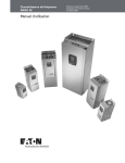
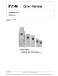
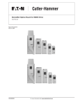
Cover Photo: Cutler-Hammer® SVX9000/SPX9000 AF Drives.
MN04001004E
For more information visit: www.eaton.com
i
9000X AF Drives User Manual
June 2009
Table of Contents
LIST OF FIGURES . . . . . . . . . . . . . . . . . . . . . . . . . . . . . . . . . . . . . . . . . . . . . . . . . . . . . . . . .
LIST OF TABLES . . . . . . . . . . . . . . . . . . . . . . . . . . . . . . . . . . . . . . . . . . . . . . . . . . . . . . . . . .
SAFETY . . . . . . . . . . . . . . . . . . . . . . . . . . . . . . . . . . . . . . . . . . . . . . . . . . . . . . . . . . . . . . . . .
Definitions and Symbols . . . . . . . . . . . . . . . . . . . . . . . . . . . . . . . . . . . . . . . . . . . . . . .
Hazardous High Voltage . . . . . . . . . . . . . . . . . . . . . . . . . . . . . . . . . . . . . . . . . . . . . . .
Warnings and Cautions . . . . . . . . . . . . . . . . . . . . . . . . . . . . . . . . . . . . . . . . . . . . . . . .
CHAPTER 1 — OVERVIEW . . . . . . . . . . . . . . . . . . . . . . . . . . . . . . . . . . . . . . . . . . . . . . . . .
How to Use This Manual . . . . . . . . . . . . . . . . . . . . . . . . . . . . . . . . . . . . . . . . . . . . . . .
Receiving and Inspection. . . . . . . . . . . . . . . . . . . . . . . . . . . . . . . . . . . . . . . . . . . . . . .
Open SVX9000/SPX9000 Catalog Numbers. . . . . . . . . . . . . . . . . . . . . . . . . . . . . . . .
CHAPTER 2 — MOUNTING . . . . . . . . . . . . . . . . . . . . . . . . . . . . . . . . . . . . . . . . . . . . . . . . .
Space Requirements . . . . . . . . . . . . . . . . . . . . . . . . . . . . . . . . . . . . . . . . . . . . . . . . . .
Environmental Requirements . . . . . . . . . . . . . . . . . . . . . . . . . . . . . . . . . . . . . . . . . . .
Standard Mounting Instructions . . . . . . . . . . . . . . . . . . . . . . . . . . . . . . . . . . . . . . . . .
CHAPTER 3 — POWER WIRING . . . . . . . . . . . . . . . . . . . . . . . . . . . . . . . . . . . . . . . . . . . . .
Guidelines . . . . . . . . . . . . . . . . . . . . . . . . . . . . . . . . . . . . . . . . . . . . . . . . . . . . . . . . . . .
UL Compatible Cable Selection and Installation . . . . . . . . . . . . . . . . . . . . . . . . . . . .
UL Compatible Cable Selection and Installation with Breaker. . . . . . . . . . . . . . . . .
Installation Instructions . . . . . . . . . . . . . . . . . . . . . . . . . . . . . . . . . . . . . . . . . . . . . . . .
Standard Wiring Diagrams and Terminal Locations . . . . . . . . . . . . . . . . . . . . . . . . .
Power and Motor Wiring Terminal Photos. . . . . . . . . . . . . . . . . . . . . . . . . . . . . . . . .
Checking the Cable and Motor Insulation . . . . . . . . . . . . . . . . . . . . . . . . . . . . . . . . .
CHAPTER 4 — CONTROL WIRING . . . . . . . . . . . . . . . . . . . . . . . . . . . . . . . . . . . . . . . . . . .
General Information. . . . . . . . . . . . . . . . . . . . . . . . . . . . . . . . . . . . . . . . . . . . . . . . . . .
Control Wiring Details . . . . . . . . . . . . . . . . . . . . . . . . . . . . . . . . . . . . . . . . . . . . . . . . .
CHAPTER 5 — MENU INFORMATION . . . . . . . . . . . . . . . . . . . . . . . . . . . . . . . . . . . . . . . .
Keypad Operation . . . . . . . . . . . . . . . . . . . . . . . . . . . . . . . . . . . . . . . . . . . . . . . . . . . .
Menu Navigation . . . . . . . . . . . . . . . . . . . . . . . . . . . . . . . . . . . . . . . . . . . . . . . . . . . . .
CHAPTER 6 — START-UP . . . . . . . . . . . . . . . . . . . . . . . . . . . . . . . . . . . . . . . . . . . . . . . . . .
Safety Precautions . . . . . . . . . . . . . . . . . . . . . . . . . . . . . . . . . . . . . . . . . . . . . . . . . . . .
Overview . . . . . . . . . . . . . . . . . . . . . . . . . . . . . . . . . . . . . . . . . . . . . . . . . . . . . . . . . . . .
Sequence of Operation to Commission an Induction Motor . . . . . . . . . . . . . . . . . .
Manual Tuning of the SVX9000/SPX9000 . . . . . . . . . . . . . . . . . . . . . . . . . . . . . . . . .
Closed Loop Vector Control Manual Tuning (SPX9000 Only). . . . . . . . . . . . . . . . . .
APPENDIX A — TECHNICAL DATA . . . . . . . . . . . . . . . . . . . . . . . . . . . . . . . . . . . . . . . . . . .
General . . . . . . . . . . . . . . . . . . . . . . . . . . . . . . . . . . . . . . . . . . . . . . . . . . . . . . . . . . . . .
Specifications . . . . . . . . . . . . . . . . . . . . . . . . . . . . . . . . . . . . . . . . . . . . . . . . . . . . . . . .
Power Ratings. . . . . . . . . . . . . . . . . . . . . . . . . . . . . . . . . . . . . . . . . . . . . . . . . . . . . . . .
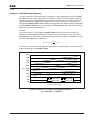
Power Loss and Switching Frequency . . . . . . . . . . . . . . . . . . . . . . . . . . . . . . . . . . . .
Dimensions . . . . . . . . . . . . . . . . . . . . . . . . . . . . . . . . . . . . . . . . . . . . . . . . . . . . . . . . . .
EMC Capability . . . . . . . . . . . . . . . . . . . . . . . . . . . . . . . . . . . . . . . . . . . . . . . . . . . . . . .
Declaration of Conformity . . . . . . . . . . . . . . . . . . . . . . . . . . . . . . . . . . . . . . . . . . . . . .
Warranty and Liability Information. . . . . . . . . . . . . . . . . . . . . . . . . . . . . . . . . . . . . . .
APPENDIX B — FAULT AND WARNING CODES . . . . . . . . . . . . . . . . . . . . . . . . . . . . . . . .
APPENDIX C — TROUBLESHOOTING CHARTS USING FAULT CODES . . . . . . . . . . . . .
APPENDIX D — SPARE PARTS . . . . . . . . . . . . . . . . . . . . . . . . . . . . . . . . . . . . . . . . . . . . . .
Series Option Board Kits . . . . . . . . . . . . . . . . . . . . . . . . . . . . . . . . . . . . . . . . . . . . . . .
Drive Options . . . . . . . . . . . . . . . . . . . . . . . . . . . . . . . . . . . . . . . . . . . . . . . . . . . . . . . .
Spare Units & Replacement Parts for 9000X Drives . . . . . . . . . . . . . . . . . . . . . . . . .
ii
For more information visit: www.eaton.com
iii
v
vii
vii
vii
viii
1-1
1-1
1-1
1-2
2-1
2-1
2-2
2-2
3-1
3-1
3-2
3-6
3-8
3-11
3-14
3-20
4-1
4-1
4-3
5-1
5-1
5-3
6-1
6-1
6-2
6-3
6-6
6-11
A-1
A-1
A-2
A-4
A-7
A-11
A-27
A-27
A-28
B-1
C-1
D-1
D-1
D-4
D-5
MN04001004E
9000X AF Drives User Manual
June 2009
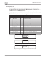
List of Figures
Figure 2-1: Mounting Space Requirements. . . . . . . . . . . . . . . . . . . . . . . . . . . . . . . . . . . . .
Figure 3-1: Input Power and Motor Cable Stripping and Wire Lengths . . . . . . . . . . . . . .
Figure 3-2: Wiring Plate . . . . . . . . . . . . . . . . . . . . . . . . . . . . . . . . . . . . . . . . . . . . . . . . . . . .
Figure 3-3: Ground Terminal Locations . . . . . . . . . . . . . . . . . . . . . . . . . . . . . . . . . . . . . . . .
Figure 3-4: Cable Protection Plate . . . . . . . . . . . . . . . . . . . . . . . . . . . . . . . . . . . . . . . . . . . .
Figure 3-5: Principle Wiring Diagram of SVX9000/SPX9000 Power Unit,
FR4 to FR5 and FR6 . . . . . . . . . . . . . . . . . . . . . . . . . . . . . . . . . . . . . . . . . . . . . . . . . . . . .
Figure 3-6: Principle Wiring Diagram of SVX9000/SPX9000 Power Unit,
FR6, FR7 and FR8 . . . . . . . . . . . . . . . . . . . . . . . . . . . . . . . . . . . . . . . . . . . . . . . . . . . . . .
Figure 3-7: Principle Wiring Diagram of SVX9000/SPX9000 Power Unit,
FR9 to FR10 . . . . . . . . . . . . . . . . . . . . . . . . . . . . . . . . . . . . . . . . . . . . . . . . . . . . . . . . . . .
Figure 3-8: FR4 Power and Motor Wiring Terminals . . . . . . . . . . . . . . . . . . . . . . . . . . . . .
Figure 3-9: FR5 Power and Motor Wiring Terminals . . . . . . . . . . . . . . . . . . . . . . . . . . . . .
Figure 3-10: FR6 Power and Motor Wiring Terminals . . . . . . . . . . . . . . . . . . . . . . . . . . . .
Figure 3-11: FR7 Power and Motor Wiring Terminals . . . . . . . . . . . . . . . . . . . . . . . . . . . .
Figure 3-12: FR8 Power and Motor Wiring Terminals . . . . . . . . . . . . . . . . . . . . . . . . . . . .
Figure 3-13: FR9 Power and Motor Wiring Terminals . . . . . . . . . . . . . . . . . . . . . . . . . . . .
Figure 4-1: Option Board Slots . . . . . . . . . . . . . . . . . . . . . . . . . . . . . . . . . . . . . . . . . . . . . . .
Figure 4-2: Option Board A9 Wiring Diagram . . . . . . . . . . . . . . . . . . . . . . . . . . . . . . . . . . .
Figure 4-3: Option Board A9 Jumper Location and Settings . . . . . . . . . . . . . . . . . . . . . .
Figure 4-4: Option Board A2 Wiring Diagram . . . . . . . . . . . . . . . . . . . . . . . . . . . . . . . . . . .
Figure 4-5: Option Board A2 Terminal Locations . . . . . . . . . . . . . . . . . . . . . . . . . . . . . . . .
Figure 4-6: Positive/Negative Logic . . . . . . . . . . . . . . . . . . . . . . . . . . . . . . . . . . . . . . . . . . .
Figure 5-1: Keypad and Display . . . . . . . . . . . . . . . . . . . . . . . . . . . . . . . . . . . . . . . . . . . . . .
Figure 5-2: Main Menu Navigation . . . . . . . . . . . . . . . . . . . . . . . . . . . . . . . . . . . . . . . . . . .
Figure 5-3: Parameter Menu Structure Example . . . . . . . . . . . . . . . . . . . . . . . . . . . . . . . .
Figure 5-4: Keypad Control Menu . . . . . . . . . . . . . . . . . . . . . . . . . . . . . . . . . . . . . . . . . . . .
Figure 5-5: Active Fault Display Example . . . . . . . . . . . . . . . . . . . . . . . . . . . . . . . . . . . . . .
Figure 5-6: Sample Fault History Display . . . . . . . . . . . . . . . . . . . . . . . . . . . . . . . . . . . . . .
Figure 5-7: System Menu Structure . . . . . . . . . . . . . . . . . . . . . . . . . . . . . . . . . . . . . . . . . . .
Figure 5-8: Expander Board Menu Structure . . . . . . . . . . . . . . . . . . . . . . . . . . . . . . . . . . .
Figure 5-9: Digital Inputs — DIN1, DIN2, DIN3 Status . . . . . . . . . . . . . . . . . . . . . . . . . . . .
Figure 5-10: Digital Inputs — DIN4, DIN5, DIN6 Status . . . . . . . . . . . . . . . . . . . . . . . . . . .
Figure 5-11: Digital and Relay Outputs — DO1, RO1, RO2 Status . . . . . . . . . . . . . . . . . .
Figure 5-12: Operate Menu Navigation . . . . . . . . . . . . . . . . . . . . . . . . . . . . . . . . . . . . . . . .
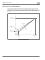
Figure 6-1: Open Loop Tuning . . . . . . . . . . . . . . . . . . . . . . . . . . . . . . . . . . . . . . . . . . . . . . .
Figure 6-2: Motor Current after V/f-Curve Tuning . . . . . . . . . . . . . . . . . . . . . . . . . . . . . . . .
Figure 6-3: Motor Equivalent Circuit . . . . . . . . . . . . . . . . . . . . . . . . . . . . . . . . . . . . . . . . . .
Figure 6-4: Left: OL Speed Control Off. Right: OL Speed Control ON. . . . . . . . . . . . . . . .
Figure 6-5: Closed Loop Motor Voltage . . . . . . . . . . . . . . . . . . . . . . . . . . . . . . . . . . . . . . . .
Figure 6-6: Closed Loop Current Limit . . . . . . . . . . . . . . . . . . . . . . . . . . . . . . . . . . . . . . . .
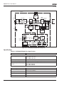
Figure A-1: SVX9000/SPX9000 Block Diagram . . . . . . . . . . . . . . . . . . . . . . . . . . . . . . . . . .
Figure A-2: Power Loss as Function of Switching Frequency —
3/4 – 3 hp 230V, 1 – 5 hp 480V . . . . . . . . . . . . . . . . . . . . . . . . . . . . . . . . . . . . . . . . . . . .
Figure A-3: Power Loss as Function of Switching Frequency —
5 – 7-1/2 hp 230V, 7-1/2 – 15 hp 480V . . . . . . . . . . . . . . . . . . . . . . . . . . . . . . . . . . . . . .
Figure A-4: Power Loss as Function of Switching Frequency —
10 – 15 hp 230V, 20 – 30 hp 480V . . . . . . . . . . . . . . . . . . . . . . . . . . . . . . . . . . . . . . . . . .
Figure A-5: Power Loss as Function of Switching Frequency —
20 – 30 hp 230V, 40 – 60 hp 480V . . . . . . . . . . . . . . . . . . . . . . . . . . . . . . . . . . . . . . . . . .
MN04001004E
For more information visit: www.eaton.com
2-1
3-8
3-9
3-10
3-10
3-11
3-12
3-13
3-14
3-15
3-16
3-17
3-18
3-19
4-1
4-3
4-5
4-5
4-6
4-6
5-1
5-4
5-5
5-6
5-7
5-9
5-10
5-18
5-19
5-19
5-19
5-21
6-6
6-8
6-9
6-10
6-12
6-13
A-2
A-7
A-8
A-8
A-9
iii
9000X AF Drives User Manual
June 2009
List of Figures (Continued)
Figure A-6: Power Loss as Function of Switching Frequency —
75 – 125 hp 480V . . . . . . . . . . . . . . . . . . . . . . . . . . . . . . . . . . . . . . . . . . . . . . . . . . . . . .
Figure A-7: Power Loss as Function of Switching Frequency —
150 – 200 hp 480V . . . . . . . . . . . . . . . . . . . . . . . . . . . . . . . . . . . . . . . . . . . . . . . . . . . . .
Figure A-8: NEMA Type 1 Enclosure Dimensions . . . . . . . . . . . . . . . . . . . . . . . . . . . . . . .
Figure A-9: NEMA Type 1 and 12 with Flange Kit, FR4, FR5 and FR6
Enclosure Dimensions . . . . . . . . . . . . . . . . . . . . . . . . . . . . . . . . . . . . . . . . . . . . . . . . .
Figure A-10: NEMA Type 1 with Flange Kit, FR7 and FR8 Enclosure Dimensions . . . . .
Figure A-11: FR9 Enclosure Dimensions . . . . . . . . . . . . . . . . . . . . . . . . . . . . . . . . . . . . . .
Figure A-12: FR9 with Flange Kit Enclosure Dimensions . . . . . . . . . . . . . . . . . . . . . . . . .
Figure A-13: SPX9000 Dimensions, FR10 Open Chassis . . . . . . . . . . . . . . . . . . . . . . . . .
Figure A-14: SPX9000 Dimensions, FR11 Open Chassis . . . . . . . . . . . . . . . . . . . . . . . . .
Figure A-15: SPX9000 Dimensions, FR13 Open Chassis Inverter . . . . . . . . . . . . . . . . . .
Figure A-16: SPX9000 Dimensions, FR13 Open Chassis Converter . . . . . . . . . . . . . . . .
Figure A-17: SPX9000 Dimensions, FR13 Open Chassis Converter —
900/1000 hp 480V . . . . . . . . . . . . . . . . . . . . . . . . . . . . . . . . . . . . . . . . . . . . . . . . . . . . . .
Figure A-18: AC Choke (CHK0650) Dimensions . . . . . . . . . . . . . . . . . . . . . . . . . . . . . . . . .
Figure A-19: AC Choke (CHK0520) Dimensions . . . . . . . . . . . . . . . . . . . . . . . . . . . . . . . . .
Figure A-20: AC Choke (CHK0400) Dimensions . . . . . . . . . . . . . . . . . . . . . . . . . . . . . . . . .
Figure A-21: AC Choke (CHK0261) Dimensions . . . . . . . . . . . . . . . . . . . . . . . . . . . . . . . . .
Figure A-22: Control Unit Dimensions . . . . . . . . . . . . . . . . . . . . . . . . . . . . . . . . . . . . . . . .
Figure A-23: Control Unit with Star-Coupler Board, FR12 or FR14 Only . . . . . . . . . . . . .
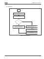
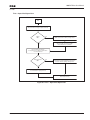
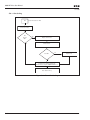
Figure C-1: F1 — Overcurrent . . . . . . . . . . . . . . . . . . . . . . . . . . . . . . . . . . . . . . . . . . . . . . .
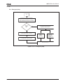
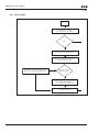
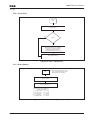
Figure C-2: F2 — Overvoltage . . . . . . . . . . . . . . . . . . . . . . . . . . . . . . . . . . . . . . . . . . . . . . .
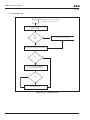
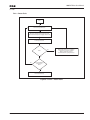
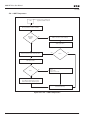
Figure C-3: F3 — Earth Fault . . . . . . . . . . . . . . . . . . . . . . . . . . . . . . . . . . . . . . . . . . . . . . . .
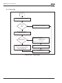
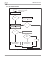
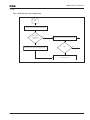
Figure C-4: F5 — Charging Switch . . . . . . . . . . . . . . . . . . . . . . . . . . . . . . . . . . . . . . . . . . .
Figure C-5: F6 — Emergency Stop . . . . . . . . . . . . . . . . . . . . . . . . . . . . . . . . . . . . . . . . . . .
Figure C-6: F7 — Saturation Trip . . . . . . . . . . . . . . . . . . . . . . . . . . . . . . . . . . . . . . . . . . . . .
Figure C-7: F8 — System Fault . . . . . . . . . . . . . . . . . . . . . . . . . . . . . . . . . . . . . . . . . . . . . .
Figure C-8: F9 — Undervoltage . . . . . . . . . . . . . . . . . . . . . . . . . . . . . . . . . . . . . . . . . . . . . .
Figure C-9: F10 — Input Line Supervision . . . . . . . . . . . . . . . . . . . . . . . . . . . . . . . . . . . . .
Figure C-10: F11 — Output Phase Supervision . . . . . . . . . . . . . . . . . . . . . . . . . . . . . . . . .
Figure C-11: F12 — Brake Chopper Supervision . . . . . . . . . . . . . . . . . . . . . . . . . . . . . . . .
Figure C-12: F13 — Frequency Converter Under Temperature . . . . . . . . . . . . . . . . . . . .
Figure C-13: F14 — Frequency Converter Over Temperature . . . . . . . . . . . . . . . . . . . . .
Figure C-14: F15 — Motor Stalled . . . . . . . . . . . . . . . . . . . . . . . . . . . . . . . . . . . . . . . . . . . .
Figure C-15: F16 — Motor Over Temperature . . . . . . . . . . . . . . . . . . . . . . . . . . . . . . . . . .
Figure C-16: F17 — Motor Under Load . . . . . . . . . . . . . . . . . . . . . . . . . . . . . . . . . . . . . . .
Figure C-17: F22 — Param Fault . . . . . . . . . . . . . . . . . . . . . . . . . . . . . . . . . . . . . . . . . . . . .
Figure C-18: F24 — Counter Fault . . . . . . . . . . . . . . . . . . . . . . . . . . . . . . . . . . . . . . . . . . . .
Figure C-19: F25 — Microprocessor Watchdog Fault . . . . . . . . . . . . . . . . . . . . . . . . . . . .
Figure C-20: F31 — IGBT Temperature (Hardware) . . . . . . . . . . . . . . . . . . . . . . . . . . . . . .
Figure C-21: F32 — Fan Cooling . . . . . . . . . . . . . . . . . . . . . . . . . . . . . . . . . . . . . . . . . . . . .
Figure C-22: F36 — Control Unit . . . . . . . . . . . . . . . . . . . . . . . . . . . . . . . . . . . . . . . . . . . . .
Figure C-23: F37 — Device Change (Indication Only) . . . . . . . . . . . . . . . . . . . . . . . . . . . .
Figure C-24: F38 — Device Added (Indication Only) . . . . . . . . . . . . . . . . . . . . . . . . . . . . .
Figure C-25: F39 — Device Removed (Indication Only) . . . . . . . . . . . . . . . . . . . . . . . . . .
Figure C-26: F40 — Device Unknown . . . . . . . . . . . . . . . . . . . . . . . . . . . . . . . . . . . . . . . . .
Figure C-27: F41 — IGBT Temperature . . . . . . . . . . . . . . . . . . . . . . . . . . . . . . . . . . . . . . . .
Figure C-28: F42 — Brake Resistor Over Temperature . . . . . . . . . . . . . . . . . . . . . . . . . . .
iv
For more information visit: www.eaton.com
A-9
A-10
A-11
A-12
A-13
A-14
A-15
A-16
A-17
A-18
A-19
A-20
A-21
A-22
A-23
A-24
A-25
A-26
C-1
C-2
C-3
C-4
C-5
C-6
C-7
C-8
C-9
C-10
C-11
C-12
C-13
C-14
C-15
C-16
C-17
C-18
C-18
C-19
C-20
C-21
C-21
C-22
C-22
C-23
C-24
C-25
MN04001004E
9000X AF Drives User Manual
June 2009
List of Figures (Continued)
Figure C-29: F44 — DevParChange . . . . . . . . . . . . . . . . . . . . . . . . . . . . . . . . . . . . . . . . . . .
Figure C-30: F45 — DevParAdded . . . . . . . . . . . . . . . . . . . . . . . . . . . . . . . . . . . . . . . . . . . .
Figure C-31: F50 — Analog Input Iin < 4 mA . . . . . . . . . . . . . . . . . . . . . . . . . . . . . . . . . . . .
Figure C-32: F51 — External Fault . . . . . . . . . . . . . . . . . . . . . . . . . . . . . . . . . . . . . . . . . . . .
Figure C-33: F52 — Keypad Communication Fault . . . . . . . . . . . . . . . . . . . . . . . . . . . . . . .
Figure D-1: 9000X Series Option Boards . . . . . . . . . . . . . . . . . . . . . . . . . . . . . . . . . . . . . . .
C-26
C-27
C-28
C-29
C-30
D-1
List of Tables
Table 1-1: SVX9000/SPX9000 AF Drive Catalog Numbering System . . . . . . . . . . . . . . . .
Table 2-1: Space Requirements for Mounting a SVX9000/SPX9000 Drive . . . . . . . . . . . .
Table 2-2: Cooling Airflow Requirements . . . . . . . . . . . . . . . . . . . . . . . . . . . . . . . . . . . . . .
Table 3-1: Cable Spacings . . . . . . . . . . . . . . . . . . . . . . . . . . . . . . . . . . . . . . . . . . . . . . . . . . .
Table 3-2: 40°C Cable and Fuse Sizes — 230V Ratings . . . . . . . . . . . . . . . . . . . . . . . . . . . .
Table 3-3: 40°C Cable and Fuse Sizes — 480V Ratings . . . . . . . . . . . . . . . . . . . . . . . . . . . .
Table 3-4: 40°C Cable and Fuse Sizes — 575V Ratings . . . . . . . . . . . . . . . . . . . . . . . . . . . .
Table 3-5: Cable and Busbar Sizes, SPX FR10 – FR12 — 480V Ratings . . . . . . . . . . . . . . .
Table 3-6: Cable and Busbar Sizes, SPX FR13 – FR14 — 480V Ratings . . . . . . . . . . . . . . .
Table 3-7: Cable and Busbar Sizes, SPX FR10 – FR12 — 575V Ratings . . . . . . . . . . . . . . .
Table 3-8: Cable and Busbar Sizes, SPX FR13 – FR14 — 575V Ratings . . . . . . . . . . . . . . .
Table 3-9: Maximum Symmetrical Supply Current . . . . . . . . . . . . . . . . . . . . . . . . . . . . . . .
Table 3-10: Cable and Breaker Sizes – 230V Ratings . . . . . . . . . . . . . . . . . . . . . . . . . . . .
Table 3-11: Cable and Breaker Sizes – 480V Ratings . . . . . . . . . . . . . . . . . . . . . . . . . . . .
Table 3-12: Cable and Breaker Sizes – 575V Ratings . . . . . . . . . . . . . . . . . . . . . . . . . . . .
Table 3-13: Power Connection Tightening Torque. . . . . . . . . . . . . . . . . . . . . . . . . . . . . . . .
Table 3-14: Power and Motor Cable Stripping Lengths . . . . . . . . . . . . . . . . . . . . . . . . . . .
Table 4-1: Tightening Torques of Terminals . . . . . . . . . . . . . . . . . . . . . . . . . . . . . . . . . . . . .
Table 4-2: Control Wiring Instructions . . . . . . . . . . . . . . . . . . . . . . . . . . . . . . . . . . . . . . . . .
Table 4-3: Option Board A9 Terminal Descriptions . . . . . . . . . . . . . . . . . . . . . . . . . . . . . . .
Table 4-4: Option Board A2 Terminal Descriptions . . . . . . . . . . . . . . . . . . . . . . . . . . . . . . .
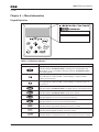
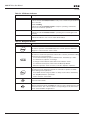
Table 5-1: LCD Status Indicators . . . . . . . . . . . . . . . . . . . . . . . . . . . . . . . . . . . . . . . . . . . . .
Table 5-2: LED Status Indicators . . . . . . . . . . . . . . . . . . . . . . . . . . . . . . . . . . . . . . . . . . . . .
Table 5-3: Navigation Buttons . . . . . . . . . . . . . . . . . . . . . . . . . . . . . . . . . . . . . . . . . . . . . . . .
Table 5-4: Fault Types . . . . . . . . . . . . . . . . . . . . . . . . . . . . . . . . . . . . . . . . . . . . . . . . . . . . . .
Table 5-5: Fault Time Data . . . . . . . . . . . . . . . . . . . . . . . . . . . . . . . . . . . . . . . . . . . . . . . . . . .
Table 5-6: Total Counters . . . . . . . . . . . . . . . . . . . . . . . . . . . . . . . . . . . . . . . . . . . . . . . . . . . .
Table 5-7: Trip Counters . . . . . . . . . . . . . . . . . . . . . . . . . . . . . . . . . . . . . . . . . . . . . . . . . . . .
Table 5-8: Software Information . . . . . . . . . . . . . . . . . . . . . . . . . . . . . . . . . . . . . . . . . . . . . .
Table 5-9: Application Information . . . . . . . . . . . . . . . . . . . . . . . . . . . . . . . . . . . . . . . . . . . .
Table 5-10: Hardware Information . . . . . . . . . . . . . . . . . . . . . . . . . . . . . . . . . . . . . . . . . . . .
Table 5-11: Expander Board Information . . . . . . . . . . . . . . . . . . . . . . . . . . . . . . . . . . . . . . .
Table 5-12: Monitoring Menu Items — Standard Application Example . . . . . . . . . . . . . .
Table 5-13: Operate Menu Items — Standard Application Example . . . . . . . . . . . . . . . . .
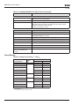
Table A-1: SVX9000/SPX9000 Drive Specifications . . . . . . . . . . . . . . . . . . . . . . . . . . . . . .
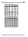
Table A-2: Output Power Ratings — 230V IH . . . . . . . . . . . . . . . . . . . . . . . . . . . . . . . . . . .
Table A-3: Output Power Ratings — 480V IH . . . . . . . . . . . . . . . . . . . . . . . . . . . . . . . . . . .
Table A-4: Output Power Ratings — 480V SPX FR10 – FR14 . . . . . . . . . . . . . . . . . . . . . . .
Table A-5: Output Power Ratings — 575V IH . . . . . . . . . . . . . . . . . . . . . . . . . . . . . . . . . . .
Table A-6: Output Power Ratings — 575V SPX FR10 – FR14 . . . . . . . . . . . . . . . . . . . . . . .
Table A-7: NEMA Type 1/Type 12 Enclosure Dimensions . . . . . . . . . . . . . . . . . . . . . . . . . .
Table A-8: FR4, FR5 and FR6 with Flange Kit Enclosure Dimensions . . . . . . . . . . . . . . . .
Table A-9: FR7 and FR8 with Flange Kit Enclosure Dimensions. . . . . . . . . . . . . . . . . . . . .
MN04001004E
For more information visit: www.eaton.com
1-2
2-1
2-2
3-1
3-2
3-3
3-4
3-4
3-5
3-5
3-5
3-5
3-6
3-6
3-7
3-8
3-9
4-2
4-2
4-4
4-6
5-1
5-2
5-2
5-8
5-8
5-15
5-16
5-16
5-16
5-17
5-17
5-19
5-20
A-2
A-4
A-5
A-5
A-6
A-6
A-11
A-12
A-13
v
9000X AF Drives User Manual
June 2009
List of Tables (Continued)
Table A-10: FR9 Enclosure Dimensions. . . . . . . . . . . . . . . . . . . . . . . . . . . . . . . . . . . . . . . .
Table A-11: FR9 with Flange Kit Enclosure Dimensions . . . . . . . . . . . . . . . . . . . . . . . . . .
Table A-12: Dimensions for SPX9000, FR10 Open Chassis . . . . . . . . . . . . . . . . . . . . . . . .
Table A-13: Dimensions for SPX9000, FR11 Open Chassis . . . . . . . . . . . . . . . . . . . . . . . .
Table A-14: Dimensions for SPX9000, FR13 Open Chassis Inverter . . . . . . . . . . . . . . . . .
Table A-15: FR13 — Number of Input Units . . . . . . . . . . . . . . . . . . . . . . . . . . . . . . . . . . . .
Table A-16: Dimensions for SPX9000, FR13 Open Chassis Converter . . . . . . . . . . . . . . .
Table A-17: FR13 — Number of Input Units . . . . . . . . . . . . . . . . . . . . . . . . . . . . . . . . . . . .
Table A-18: Dimensions for SPX9000, FR13 Open Chassis Converter —
900/1000 hp 480V . . . . . . . . . . . . . . . . . . . . . . . . . . . . . . . . . . . . . . . . . . . . . . . . . . . . . .
Table B-1: Fault Codes . . . . . . . . . . . . . . . . . . . . . . . . . . . . . . . . . . . . . . . . . . . . . . . . . . . . .
Table D-1: Option Board Kits . . . . . . . . . . . . . . . . . . . . . . . . . . . . . . . . . . . . . . . . . . . . . . . .
Table D-2: Control Panel Factory Options . . . . . . . . . . . . . . . . . . . . . . . . . . . . . . . . . . . . . .
Table D-3: 9000X Spare Units . . . . . . . . . . . . . . . . . . . . . . . . . . . . . . . . . . . . . . . . . . . . . . .
Table D-4: Replacement Parts — 9000X Drives, 208 – 240V . . . . . . . . . . . . . . . . . . . . . . .
Table D-5: Replacement Parts — FR4 – FR9 9000X Drives, 380 – 500V . . . . . . . . . . . . . .
Table D-6: Replacement Parts — FR10 – FR12 9000X Drives, 380 – 500V . . . . . . . . . . . .
Table D-7: Replacement Parts — FR6 – FR9 9000X Drives, 525 – 690V . . . . . . . . . . . . . .
Table D-8: Replacement Parts — FR10 – FR12 9000X Drives, 525 – 690V . . . . . . . . . . . .
Table D-9: Power Module Catalog Number Matrix . . . . . . . . . . . . . . . . . . . . . . . . . . . . . .
Table A-10: FR9 Enclosure Dimensions. . . . . . . . . . . . . . . . . . . . . . . . . . . . . . . . . . . . . . . .
vi
For more information visit: www.eaton.com
A-14
A-15
A-16
A-17
A-18
A-19
A-19
A-20
A-20
B-1
D-1
D-4
D-5
D-5
D-7
D-9
D-11
D-13
D-14
A-14
MN04001004E
9000X AF Drives User Manual
June 2009
Safety
Definitions and Symbols
WARNING
This symbol indicates high voltage. It calls your attention to items
or operations that could be dangerous to you and other persons
operating this equipment. Read the message and follow the
instructions carefully.
This symbol is the “Safety Alert Symbol.” It occurs with either of
two signal words: CAUTION or WARNING, as described below.
WARNING
Indicates a potentially hazardous situation which, if not avoided,
can result in serious injury or death.
CAUTION
Indicates a potentially hazardous situation which, if not avoided,
can result in minor to moderate injury, or serious damage to the
equipment. The situation described in the CAUTION may, if not
avoided, lead to serious results. Important safety measures are
described in CAUTION (as well as WARNING).
Hazardous High Voltage
WARNING
Motor control equipment and electronic controllers are connected
to hazardous line voltages. When servicing drives and electronic
controllers, there may be exposed components with housings or
protrusions at or above line potential. Extreme care should be taken
to protect against shock.
• Stand on an insulating pad and make it a habit to use only one
hand when checking components.
• Always work with another person in case an emergency occurs.
• Disconnect power before checking controllers or performing
maintenance.
• Be sure equipment is properly grounded.
• Wear safety glasses whenever working on electronic controllers
or rotating machinery.
MN04001004E
For more information visit: www.eaton.com
vii
9000X AF Drives User Manual
June 2009
Warnings and Cautions
Read this manual thoroughly and make sure you understand the procedures before you
attempt to install, set up, or operate this Cutler-Hammer® SVX9000/SPX9000 Adjustable
Frequency Drive from Eaton’s electrical business.
Warnings
WARNING
Be sure to ground the unit following the instructions in this manual.
Ungrounded units may cause electric shock and/or fire.
WARNING
This equipment should be installed, adjusted, and serviced by
qualified electrical maintenance personnel familiar with the
construction and operation of this type of equipment and the
hazards involved. Failure to observe this precaution could result in
death or severe injury.
WARNING
Components within the SVX9000/SPX9000 power unit are live
when the drive is connected to power. Contact with this voltage is
extremely dangerous and may cause death or severe injury.
WARNING
Line terminals (L1, L2, L3), motor terminals (U, V, W) and the DClink/brake resistor terminals (-/+) are live when the drive is
connected to power, even if the motor is not running. Contact with
this voltage is extremely dangerous and may cause death or severe
injury.
WARNING
Even though the control I/O-terminals are isolated from line
voltage, the relay outputs and other I/O-terminals may have
dangerous voltage present even when the drive is disconnected
from power. Contact with this voltage is extremely dangerous and
may cause death or severe injury.
WARNING
The SVX9000/SPX9000 drive has a large capacitive leakage current
during operation, which can cause enclosure parts to be above
ground potential. Proper grounding, as described in this manual, is
required. Failure to observe this precaution could result in death or
severe injury.
WARNING
Before applying power to the SVX9000/SPX9000 drive, make sure
that the front and cable covers are closed and fastened to prevent
exposure to potential electrical fault conditions. Failure to observe
this precaution could result in death or severe injury.
viii
For more information visit: www.eaton.com
MN04001004E
9000X AF Drives User Manual
June 2009
WARNING
An upstream disconnect/protective device must be provided as
required by the National Electric Code (NEC). Failure to follow this
precaution may result in death or severe injury.
WARNING
Before opening the SVX9000/SPX9000 drive covers:
• Disconnect all power to the SVX9000/SPX9000 drive.
• Wait a minimum of 5 (five) minutes after all the lights on the
keypad are off. This allows time for the DC bus capacitors to
discharge.
• A hazard voltage may still remain in the DC bus capacitors even
if the power has been turned off. Confirm that the capacitors
have fully discharged by measuring their voltage using a
multimeter set to measure DC voltage.
Failure to follow the above precautions may cause death or severe
injury.
Cautions
CAUTION
Do not perform any meggar or voltage withstand tests on any part
of the SVX9000/SPX9000 drive or its components. Improper testing
may result in damage.
CAUTION
Prior to any tests or measurements of the motor or the motor cable,
disconnect the motor cable at the SVX9000/SPX9000 output
terminals (U, V, W) to avoid damaging the SVX9000/SPX9000
during motor or cable testing.
CAUTION
Do not touch any components on the circuit boards. Static voltage
discharge may damage the components.
CAUTION
Any electrical or mechanical modification to this equipment
without prior written consent of Eaton will void all warranties and
may result in a safety hazard in addition and voiding of the UL
listing.
CAUTION
Install the SVX9000/SPX9000 drive on flame-resistant material such
as a steel plate to reduce the risk of fire.
MN04001004E
For more information visit: www.eaton.com
ix
9000X AF Drives User Manual
June 2009
CAUTION
Install the SVX9000/SPX9000 drive on a perpendicular surface that
is able to support the weight of the drive and is not subject to
vibration, to lessen the risk of the drive falling and being damaged
and/or causing personal injury.
CAUTION
Prevent foreign material such as wire clippings or metal shavings
from entering the drive enclosure, as this may cause arcing
damage and fire.
CAUTION
Install the SVX9000/SPX9000 drive in a well-ventilated room that is
not subject to temperature extremes, high humidity, or
condensation, and avoid locations that are directly exposed to
sunlight, or have high concentrations of dust, corrosive gas,
explosive gas, inflammable gas, grinding fluid mist, etc. Improper
installation may result in a fire hazard.
Motor and Equipment Safety
CAUTION
Before starting the motor, check that the motor is mounted properly
and aligned with the driven equipment. Ensure that starting the
motor will not cause personal injury or damage equipment
connected to the motor.
CAUTION
Set the maximum motor speed (frequency) in the SVX9000/
SPX9000 drive according to the requirements of the motor and the
equipment connected to it. Incorrect maximum frequency settings
can cause motor or equipment damage and personal injury.
CAUTION
Before reversing the motor rotation direction, ensure that this will
not cause personal injury or equipment damage.
CAUTION
Make sure that no power correction capacitors are connected to the
SVX9000/SPX9000 output or the motor terminals to prevent
SVX9000/SPX9000 malfunction and potential damage.
CAUTION
Make sure that the SVX9000/SPX9000 output terminals (U, V, W)
are not connected to the utility line power as severe damage to the
SVX9000/SPX9000 may occur.
x
For more information visit: www.eaton.com
MN04001004E
9000X AF Drives User Manual
June 2009
Chapter 1 — Overview
This chapter describes the purpose and contents of this manual, the receiving inspection
recommendations and the Cutler-Hammer® SVX9000/SPX9000 catalog numbering system.
How to Use This Manual
The purpose of this manual is to provide you with information necessary to install, set and
customize parameters, start up, troubleshoot and maintain the Cutler-Hammer SVX9000/
SPX9000 AF Drives by Eaton’s electrical business. To provide for safe installation and
operation of the equipment, read the safety guidelines at the beginning of this manual and
follow the procedures outlined in the following chapters before connecting power to the
SVX9000/SPX9000. Keep this user manual handy and distribute to all users, technicians and
maintenance personnel for reference along with the appropriate application manual.
Chapter 1 – Overview is the chapter you are reading now.
Chapter 2 – Mounting
Chapter 3 – Power Wiring
Chapter 4 – Control Wiring
Chapter 5 – Menu Information
Chapter 6 – Start-Up
Appendix A – Technical Data
Appendix B – Fault and Warning Codes
Appendix C – Troubleshooting Charts
Appendix D – Spare Parts
Receiving and Inspection
This SVX9000/SPX9000 AC drive has met a stringent series of factory quality requirements
before shipment. It is possible that packaging or equipment damage may have occurred
during shipment. After receiving your SVX9000/SPX9000 drive, please check for the
following:
●
●
●
Check to make sure that the package(s) includes the proper drive, the User Manual, and
rubber conduit covers, screws, conduit plate and ground straps.
Inspect the unit to ensure it was not damaged during shipment.
Make sure that the part number indicated on the nameplate corresponds with the
Catalog Number on your order.
If shipping damage has occurred, please contact and file a claim with the carrier involved
immediately.
If the delivery does not correspond to your order, please contact your Eaton representative.
Note: Do not destroy the packing. The template printed on the protective cardboard can be
used for marking the mounting points of the SVX9000/SPX9000 AF Drives on the wall
or cabinet.
MN04001004E
For more information visit: www.eaton.com
1-1
9000X AF Drives User Manual
June 2009
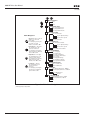
Open SVX9000/SPX9000 Catalog Numbers
Table 1-1: SVX9000/SPX9000 AF Drive Catalog Numbering System
SVX 007A 1 - 4 A 1 B 1
Expansion Slots 3 through 5
Product
• Option boards be selected from left
to right, in alpha-numeric order.
• Characters to be left blank if no
options are selected
SVX = SVX Industrial Drive
SPX = SPX Drive
Horsepower (IH) F07 = 3/4
001 = 1
F15 = 1-1/2
002 = 2
003 = 3
004 = 5 IL Only
005 = 5
006 = 7-1/2 IL Only
007 = 7-1/2
010 = 10
015 = 15
020 = 20
025 = 25
030 = 30
040 = 40
050 = 50
060 = 60
075 = 75
100 = 100
125 = 125
150 = 150
200 = 200
250 = 250
300 = 300
350 = 350
400 = 400
500 = 500
550 = 550
600 = 600
650 = 650
700 = 700
800 = 800
900 = 900
H10 = 1000
H12 = 1200
H13 = 1350
H15 = 1500
H16 = 1600
H20 = 2000
AFD Software Series
A = Standard Software
Board Modifications
1 = Standard Boards (A9, A2)
Braking
N = No Brake Chopper B = Internal Brake Chopper Input Options 1 = 3-Phase, EMC H
2 = 3-Phase, EMC N
4 = 3-Phase, EMC L
Keypad
A = AlphaNumeric
Voltage
2 = 208 – 230V
4 = 380 – 500V
5 = 525 – 690V
Enclosure 0 = Open Chassis
1 = NEMA Type 1
2 = NEMA Type 12
1-2
All 230V Drives and 480V Drives up to 200 hp (IH) are only available with Input Option 1.
480V Drives 250 hp (IH) or larger are only available with Input Option 2.
480V Drives up to 30 hp (IH) are only available with Brake Chopper Option B.
480V Drives 40 hp (IH) and larger come with Brake Chopper Option N as standard.
230V Drives up to 15 hp (IH) are only available with Brake Chopper Option B.
230V Drives 20 hp (IH) or larger come with Brake Chopper Option N as standard.
480V Drives 250 hp, 300 hp and 350 hp (IH) are only available with Enclosure Style 0 (Chassis).
For more information visit: www.eaton.com
MN04001004E
9000X AF Drives User Manual
June 2009
Chapter 2 — Mounting
The SVX9000/SPX9000 drive may be mounted side-by-side or stacked vertically, as outlined
in the following section.
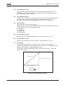
Space Requirements
To ensure proper air circulation and cooling, follow the guidelines below.
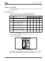
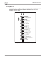
Table 2-1: Space Requirements for Mounting a SVX9000/SPX9000 Drive
Dimensions in Inches (mm) Frame
Drive Type
A
A2
B
C
4
230V, 1 – 3 hp IL, 3/4 – 3 hp IH
480V, 1 – 5 hp IH, 1-1/2 – 7-1/2 hp IL
0.8
(20)
—
0.8
(20)
3.9 (100) 2.0
(50)
5
230V, 5 – 10 hp IL, 5 – 7-1/2 hp IH
480V, 7-1/2 – 15 hp IH, 10 – 20 hp IL
1.2
(30)
—
0.8
(20)
4.7 (120) 2.4
(60)
6
230V, 15 – 20 hp IL, 10 – 15 hp IH
480V, 20 – 30 hp IH, 25 – 40 hp IL
575V, 2 – 25 hp IH, 3 – 30 hp IL
1.2
(30)
—
0.8
(20)
6.3 (160) 3.1
(80)
7
230V, 25 – 40 hp IL, 20 – 30 hp IH
480V, 40 – 60 hp IH, 50 – 75 hp IL
575V, 30 – 40 hp IH, 40 – 50 hp IL
3.1
(80)
—
3.1
(80)
11.8
(300)
3.9 (100)
8
480V, 75 – 125 hp IH, 100 – 150 hp IL
575V, 50 – 75 hp IH, 60 – 100 hp IL
3.1
(80)
5.9 (150) 3.1
(80)
11.8
(300)
7.9 (200)
9
480V, 200 – 250 hp IL, 150 – 200 hp IH
575V, 100 – 150 hp IH, 150 – 200 hp IL
2.0
(50)
—
15.7
(400)
9.8 (250)
13.8
(350) 3.1
(80)
D
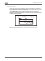
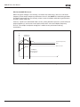
Dimensions represent the minimum clearance needed when mounting a SVX9000/SPX9000. See Figure 2-1 below.
A = clearance around the SVX9000/SPX9000.
A2 = clearance needed to change the fan without disconnecting the motor cables.
B = distance between adjacent SVX9000/SPX9000 drives or between the SVX9000/SPX9000 and an enclosure wall.
C = clearance above the SVX9000/SPX9000.
D = clearance below the SVX9000/SPX9000.
Minimum clearance below the SVX9000/SPX9000 needed to change the fan.
C
B
A
A2
B
A
A2
D
Figure 2-1: Mounting Space Requirements.
If several units are mounted above each other, the clearance between the drives should equal
C + D (see Table 2-1 and Figure 2-1 above). In addition, the outlet air used for cooling the
lower unit must be directed away from the inlet air used by the upper unit.
MN04001004E
For more information visit: www.eaton.com
2-1
9000X AF Drives User Manual
June 2009
Environmental Requirements
Ensure that the environment meets the requirements listed in Table A-1 of Appendix A for
any storage or operating situation.
Table 2-2 specifies the minimum airflow required in the area where the drive will be
mounted.
Table 2-2: Cooling Airflow Requirements
Drive Type
Cooling Air Required
230V, 3/4 – 3 hp IH
480V, 1 – 5 hp IH
41 cfm (70 m3/h)
230V, 5 – 7-1/2 hp IH
480V, 7-1/2 – 15 hp IH
112 cfm (190 m3/h)
230V, 10 – 15 hp IH
480V, 20 – 30 hp IH
575V, 2 – 25 hp IH
250 cfm (425 m3/h)
230V, 20 – 30 hp IH
480V, 40 – 60 hp IH
575V, 30 – 40 hp IH
250 cfm (425 m3/h)
480V, 75 – 125 hp IH
575V, 60 – 75 hp IH
383 cfm (650 m3/h)
480V, 150 – 200 hp IH
575V, 100 – 150 hp IH
765 cfm (1300 m3/h)
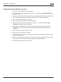
Standard Mounting Instructions
1. Measure the mounting space to ensure that it allows for the minimum space
surrounding the drive. Drive dimensions are in Appendix A.
2. Make sure the mounting surface is flat and strong enough to support the drive, is not
flammable, and is not subject to excessive motion or vibration.
3. Ensure that the minimum airflow requirements for your drive are met at the mounting
location.
4. Mark the location of the mounting holes on the mounting surface, using the template
provided on the cover of the cardboard shipping package.
5. Using fasteners appropriate to your drive and mounting surface, securely attach the
drive to the mounting surface using all 4 screws or bolts.
2-2
For more information visit: www.eaton.com
MN04001004E
9000X AF Drives User Manual
June 2009
Chapter 3 — Power Wiring
Guidelines
To ensure proper wiring, use the following guidelines:
●
●
●
Use heat-resistant copper cables only, +75°C or higher.
The input line cable and line fuses must be sized in accordance with the rated input
current of the unit. See Tables 3-2 through 3-8.
Provide a ground wire with both input power and output motor leads.
The control should be installed in accordance with all applicable codes. In accordance with
NEC 430 Part IV, a protective device is required in the installation of the control. This
protective device can be either a fuse or circuit breaker. An RK fuse is an acceptable
component. For maximum protection Eaton recommends a Class T fuse.
Input line cable and line fuses must be sized in accordance with Tables 3-2 through 3-6.
●
●
●
●
If the motor temperature sensing is used for overload protection, the output cable size
may be selected based on the motor specifications.
If three or more shielded cables are used in parallel for the output on the larger units,
every cable must have its own overload protection.
Avoid placing the motor cables in long parallel lines with other cables.
If the motor cables run in parallel with other cables, note the minimum distances
between the motor cables and other cables given in Table 3-1 below:
Table 3-1: Cable Spacings
●
●
Minimum Distance Between
Cables in Feet (m)
Cable in Feet (m)
1 (0.3)
≤ 164 (50)
3.3 (1.0)
≤ 656 (200)
The spacings of Table 3-1 also apply between the motor cables and signal cables of
other systems.
The maximum length of the motor cables is as follows:
– 1 – 2 hp, 230V units, 328 ft. (100m)
– All other hp units, 984 ft. (300m)
●
●
MN04001004E
The motor cables should cross other cables at an angle of 90 degrees.
If conduit is being used for wiring, use separate conduits for the input power wiring,
the output power wiring, the signal wiring and the control wiring.
For more information visit: www.eaton.com
3-1
9000X AF Drives User Manual
June 2009
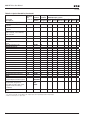
UL Compatible Cable Selection and Installation
Use only copper wire with temperature rating of at least 75°C.
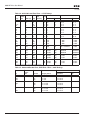
Table 3-2: 40°C Cable and Fuse Sizes — 230V Ratings
IL hp
Wire Size
Terminal Size
Fuse Fuse
Quantity [A]
Power
Ground Power
Ground
1
1-1/2
2
3
FR4
4.2
6
6.8
9.6
4.8
6.6
7.8
11
3
3
3
3
10
10
10
15
14
14
14
14
14
14
14
14
16 – 12
16 – 12
16 – 12
16 – 12
16 – 14
16 – 14
16 – 14
16 – 14
5
7-1/2
10
FR5
15.2
22
28
17.5
25
31
3
3
3
20
30
40
12
10
8
12
10
8
16 – 8
16 – 8
16 – 8
16 – 8
16 – 8
16 – 8
15
20
FR6
42
54
48
61
3
3
60
80
4
2
8
6
14 – 0
14 – 0
10 – 2
10 – 2
25
30
40
FR7
68
80
104
72
87
114
3
3
3
100
110
125
2
1
1/0
6
6
4
14 – 0
14 – 0
14 – 0
10 – 00
10 – 00
10 – 00
50
60
75
FR8
130
154
192
140
170
205
3
3
3
175
200
250
3/0
4/0
300
2
0
2/0
4 – 3/0
000 – 350 MCM
000 – 350 MCM
4 – 000
4 – 000
4 – 000
100
FR9
248
261
3
300
2x4/0
3/0
2x000 – 350 MCM
4 – 000
3-2
Frame
Size
NEC I [A] I [A]
UL recognized type JJS preferred but RK acceptable.
For more information visit: www.eaton.com
MN04001004E
9000X AF Drives User Manual
June 2009
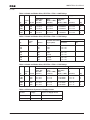
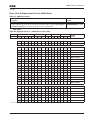
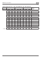
Table 3-3: 40°C Cable and Fuse Sizes — 480V Ratings
IL hp
Wire Size
Terminal Size
Fuse Fuse
Quantity [A]
Power
Ground Power
Ground
1-1/2
2
3
5
7-1/2
FR4
3
3.4
4.8
7.6
11
3.3
4.3
5.6
7.6
12
3
3
3
3
3
10
10
10
10
15
14
14
14
14
12
14
14
14
14
14
16 – 12
16 – 12
16 – 12
16 – 12
16 – 12
16 – 14
16 – 14
16 – 14
16 – 14
16 – 14
10
15
20
FR5
14
21
27
16
23
31
3
3
3
20
30
35
10
10
8
12
10
8
16 – 8
16 – 8
16 – 8
16 – 8
16 – 8
16 – 8
25
30
40
FR6
34
40
52
38
46
61
3
3
3
50
60
80
6
4
2
8
8
6
14 – 0
14 – 0
14 – 0
10 – 2
10 – 2
10 – 2
50
60
75
FR7
65
77
96
72
87
105
3
3
3
100
110
125
2
1
1/0
6
6
4
14 – 0
14 – 0
14 – 0
10 – 00
10 – 00
10 – 00
100
125
150
FR8
124
156
180
140
170
205
3
3
3
175
200
250
3/0
4/0
300
2
0
2/0
4 – 3/0
000 – 350 MCM
000 – 350 MCM
4 – 000
4 – 000
4 – 000
200
250
FR9
240
302
261
300
3
3
350
400
2x4/0
2x250
3/0
300
2x000 – 350 MCM
2x000 – 350 MCM
4 – 000
4 – 000
300
350
400
FR10
361
414
477
385
460
520
3
3
3
450
500
600
2x250
2x300
2x400
300
300
350
600 MCM
600 MCM
600 MCM
300 MCM
300 MCM
300 MCM
500
550
600
FR11
590
NS
NS
590
650
730
6
6
6
350
400
450
2x500
4x4/0
4x250
500
500
600
Bus Bar
Bus Bar
Bus Bar
Bus Bar
Bus Bar
Bus Bar
650
700
800
FR12
NS
NS
NS
820 6
920 6
1030 6
500
500
600
4x300
4x300
4x350
600
600
Bus Bar
Bus Bar
Bus Bar
Bus Bar
Bus Bar
Bus Bar
MN04001004E
Frame
Size
NEC I [A] I [A]
UL recognized type JJS preferred but RK acceptable.
For more information visit: www.eaton.com
3-3
9000X AF Drives User Manual
June 2009
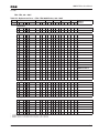
Table 3-4: 40°C Cable and Fuse Sizes — 575V Ratings
IL hp
3
5
7-1/2
10
Frame
Size
NEC I [A] I [A]
FR6
15
20
25
30
Wire Size
Terminal Size
Fuse Fuse
Quantity [A]
Power
Ground Power
Ground
3.9
6.1
9
11
4.5
7.5
10
13.5
3
3
3
3
10
10
15
20
14
14
12
12
14
14
14
12
14 – 0
14 – 0
14 – 0
14 – 0
14 – 2
14 – 2
14 – 2
14 – 2
17
22
27
32
18
22
27
34
3
3
3
3
30
35
40
45
10
8
8
6
10
8
8
8
14 – 0
14 – 0
14 – 0
14 – 0
14 – 2
14 – 2
14 – 2
14 – 2
40
50
FR7
41
52
41
52
3
3
50
70
6
4
8
6
14 – 0
14 – 0
10 – 0
10 – 0
60
75
100
125
FR8
62
77
99
125
62
80
100
125
3
3
3
3
80
125
150
175
2
1/0
2/0
3/0
6
6
6
6
4 – 000
4 – 000
4 – 000
4 – 000
4 – 000
4 – 000
4 – 000
4 – 000
150
200
FR9
144
192
144
208
3
3
250
275
300
350
1/0
2/0
000 – 350 MCM
000 – 350 MCM
4 – 000
4 – 000
250
300
400
FR10
242
289
382
261
325
385
3
3
3
350
400
450
2x4/0
2x250
2x300
3/0
300
300
600 MCM
600 MCM
600 MCM
300 MCM
300 MCM
300 MCM
450
500
550
FR11
412
472
NS
460
502
590
6
6
6
250
300
350
2x300
2x350
2x500
300
350
500
Bus Bar
Bus Bar
Bus Bar
Bus Bar
Bus Bar
Bus Bar
600
700
800
FR12
NS
NS
NS
650
750
820
6
6
6
400
450
500
4x4/0
4x250
4x300
500
600
600
Bus Bar
Bus Bar
Bus Bar
Bus Bar
Bus Bar
Bus Bar
UL recognized type JJS preferred but RK acceptable
Table 3-5: Cable and Busbar Sizes, SPX FR10 – FR12 — 480V Ratings
hp
External Power Busbars
Current
Cu (per phase)
Cu
(in Inches)
Qty.
250
300
350
FR10
300
385
460
2 x 2/0
2 x 3/0
2 x 3/0
1.18 x 0.25
1.57 x 0.25
1.57 x 0.25
3
3
3
400
500
—
FR11
520
590
650
2 x 2 x 2/0
2 x 2 x 2/0
2 x 2 x 2/0
1.18 x 0.25
1.18 x 0.25
1.18 x 0.25
6
6
6
600
—
700
FR12
750
820
920
2 x 2 x 3/0
2 x 2 x 3/0
2 x 2 x 3/0
1.57 x 0.25
1.57 x 0.25
1.57 x 0.25
6
6
6
3-4
Frame
Size
Internal Power Cables
90°C rating recommended.
For more information visit: www.eaton.com
MN04001004E
9000X AF Drives User Manual
June 2009
Table 3-6: Cable and Busbar Sizes, SPX FR13 – FR14 — 480V Ratings
Internal Power Connections
hp
Busbar Size
Frame
NFE – INU
Size
Current (in Inches)
Supply Busbars
Busbar Size/
Phase (Choke — NFE)
(in Inches)
Cable Size/
Phase
(Choke — NFE)
Cu
(in Inches)
Qty.
800
900
1000
FR13
1030
1150
1300
2.36 x 0.39
3.15 x 0.39
3.15 x 0.39
1.57 x 0.25
1.57 x 0.25
1.57 x 0.25
2 x 300 MCM
2 x 250 MCM
2 x 250 MCM
1.57 x 0.25
1.57 x 0.25
1.57 x 0.25
6
12
12
1200
1600
FR14
1600
1940
2.36 x 0.39
2.36 x 0.39
1.57 x 0.25
1.57 x 0.25
2 x 250 MCM
2 x 300 MCM
1.57 x 0.25
1.57 x 0.25
12
12
Rigid copper connection.
Table 3-7: Cable and Busbar Sizes, SPX FR10 – FR12 — 575V Ratings
Internal Power Cables
Frame
Size hp
External Power Busbars
Current
Cu (per phase)
Cu
(in Inches)
Qty.
200
250
300
FR10
208
261
325
2x2/0
2x2/0
2x2/0
1.18 x .25
1.18 x .25
1.18 x .25
3
3
3
400
450
500
FR11
385
460
502
2x3/0
2x3/0
2x2x2/0
1.57 x .25
1.57 x .25
1.18 x .25
3
3
6
—
600
700
FR12
590
650
750
2x2x2/0
2x2x2/0
2\x2x2/0
1.18 x .25
1.18 x .25
1.18 x .25
6
6
6
90°C rating recommended.
Table 3-8: Cable and Busbar Sizes, SPX FR13 – FR14 — 575V Ratings
Internal Power Connections
hp
Busbar Size
Frame
NFE – INU
Size
Current (in Inches)
Supply Busbars
Busbar Size/
Phase (Choke — NFE)
(in Inches)
Cable Size/
Phase
(Choke — NFE)
Cu
(in Inches)
Qty.
800
900
1000
FR13
820
920
1030
2.36 x 0.39
2.36 x 0.39
2.36 x 0.39
1.57 x .25
1.57 x .25
1.57 x .25
2 x 300 MCM
2 x 250 MCM
2 x 300 MCM
1.18 x .25
1.18 x .25
1.18 x .25
6
6
6
1350
1500
2000
FR14
1300
1500
1900
3.15 x 0.39
2.36 x 0.39
2.36 x 0.39
1.57 x .25
1.57 x .25
1.57 x .25
2 x 250 MCM
2 x 250 MCM
2 x 300 MCM
1.18 x .25
1.18 x .25
1.18 x .25
12
12
12
Rigid copper connection.
Table 3-9: Maximum Symmetrical Supply Current
MN04001004E
Product
Voltage
Maximum RMS Symmetrical
Amperes on Supply Circuit
3/4 – 30 hp
230
100,000A
1-1/2 – 200 hp
480
100,000A
For more information visit: www.eaton.com
3-5
9000X AF Drives User Manual
June 2009
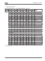
UL Compatible Cable Selection and Installation with Breaker
Use only copper wire with temperature rating of at least 75°C.
Table 3-10: Cable and Breaker Sizes – 230V Ratings
hp
Frame
Size
FLA
Breaker
Current
Wire Size Terminal Size
Power
Ground
Power
Ground
1
1-1/2
2
3
FR4
4.8
6.6
7.8
11
15
15
15
15
14
14
14
12
14
14
14
12
12 – 16
12 – 16
12 – 16
12 – 16
14 – 16
14 – 16
14 – 16
14 – 16
5
7-1/2
FR5
17.5
25
20
30
10
8
10
8
8 – 16
8 – 16
8 – 16
8 – 16
10
15
FR6
31
48
40
60
8
4
8
6
1/0 – 14
1/0 – 14
2 – 14
2 – 14
20
25
30
FR7
61
72
87
80
100
100
2
2
1/0
6
6
4
1/0 – 14
1/0 – 14
1/0 – 14
2/0 – 10
2/0 – 10
2/0 – 10
Based on a maximum environment of 104°F (40°C).
A UL listed breaker must be used.
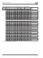
Table 3-11: Cable and Breaker Sizes – 480V Ratings
hp
Wire Size Terminal Size
FLA
Breaker
Current
Power
Ground
Power
Ground
1-1/2
2
3
5
FR4
3.3
4.3
5.6
7.6
15
15
15
15
14
14
14
14
14
14
14
14
12 – 16
12 – 16
12 – 16
12 – 16
14 – 16
14 – 16
14 – 16
14 – 16
7-1/2
10
15
FR5
12
16
23
20
30
30
12
10
8
12
10
8
8 – 16
8 – 16
8 – 16
8 – 16
8 – 16
8 – 16
20
25
30
FR6
31
38
46
40
50
60
8
6
4
8
8
6
1/0 – 14
1/0 – 14
1/0 – 14
2 – 14
2 – 14
2 – 14
40
50
60
FR7
61
72
87
80
100
100
2
2
1/0
6
6
4
1/0 – 14
1/0 – 14
1/0 – 14
2/0 – 10
2/0 – 10
2/0 – 10
75
100
125
FR8
105
140
170
125
150
200
2/0
4/0
300
2
1/0
2/0
3/0 – 4
350 MCM – 3/0
350 MCM – 3/0
3/0 – 4
3/0 – 4
3/0 – 4
150
200
FR9
205
261
250
300
350
2x250
3/0
3/0
350 MCM – 2x3/0
350 MCM – 2x3/0
3/0 – 4
3/0 – 4
250
300
350
FR10
300
385
460
400
500
600
2x250
2x300
2x400
300 MCM
300 MCM
300 MCM
600 MCM
600 MCM
600 MCM
600 MCM
600 MCM
600 MCM
400
500
550
FR11
520
590
650
700
800
900
2x500
4x4/0
4x250
500
500
600
Bus Bar
Bus Bar
Bus Bar
Bus Bar
Bus Bar
Bus Bar
600
650
700
FR12
750
820
920
1000
1000
1200
4x300
4x300
4x400
600
600
Bus Bar
Bus Bar
Bus Bar
Bus Bar
Bus Bar
Bus Bar
3-6
Frame
Size
Based on a maximum environment of 104°F (40°C).
A UL listed breaker must be used.
For more information visit: www.eaton.com
MN04001004E
9000X AF Drives User Manual
June 2009
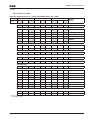
Table 3-12: Cable and Breaker Sizes – 575V Ratings
hp
2
3
5
7-1/2
Frame
Size
FR6
10
15
20
25
Wire Size Terminal Size
Power
Ground
Power
Ground
FLA
Breaker
Current
3.3
4.5
7.5
10
15
15
15
20
14
14
14
12
14
14
14
14
1/0 – 14
1/0 – 14
1/0 – 14
1/0 – 14
2 – 14
2 – 14
2 – 14
2 – 14
13.5
18
22
27
30
30
40
40
10
10
8
8
12
10
8
8
1/0 – 14
1/0 – 14
1/0 – 14
1/0 – 14
2 – 14
2 – 14
2 – 14
2 – 14
30
40
FR7
34
41
50
60
6
4
8
6
1/0 – 14
1/0 – 14
1/0 – 10
1/0 – 10
50
60
75
100
FR8
52
62
80
100
100
100
125
150
2
1
1/0
3/0
6
6
6
6
3/0 – 4
3/0 – 4
3/0 – 4
3/0 – 4
3/0 – 4
3/0 – 4
3/0 – 4
3/0 – 4
125
150
FR9
125
144
200
250
4/0
350
2
1/0
350 MCM – 2x3/0
350 MCM – 2x3/0
3/0 – 4
3/0 – 4
200
250
300
FR10
208
261
325
300
400
500
2x250
2x300
2x350
300 MCN
300 MCM
300 MCM
600 MCM
600 MCM
600 MCM
600 MCM
600 MCM
600 MCM
400
450
500
FR11
385
460
502
500
600
700
2x300
2x350
2x500
300
350
500
Bus Bar
Bus Bar
Bus Bar
Bus Bar
Bus Bar
Bus Bar
550
600
700
FR12
590
650
750
800
900
1000
4x4/0
4x250
4x300
500
600
600
Bus Bar
Bus Bar
Bus Bar
Bus Bar
Bus Bar
Bus Bar
Based on a maximum environment of 104°F (40°C).
A UL listed breaker must be used.
Note: The current interrupting of the breaker, up to 100 kAIC, will determine the overall
current rating of the combination.
MN04001004E
For more information visit: www.eaton.com
3-7
9000X AF Drives User Manual
June 2009
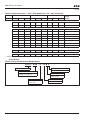
Table 3-13: Power Connection Tightening Torque
Rating
230V, 3/4 – 3 hp
480V, 1 – 5 hp
Frame Tightening Torque Tightening Torque
Size
(in-lbs)
(Nm)
5
5
0.6
0.6
230V, 5 – 7-1/2 hp FR5
480V, 7-1/2 – 15 hp
13
13
1.5
1.5
230V, 10 – 15 hp
480V, 20 – 30 hp
575V, 2 – 25 hp
FR6
35
35
35
4
4
4
230V, 20 – 30 hp
480V, 40 – 60 hp
575V, 30 – 40 hp
FR7
85
85
85
10
10
10
480V, 75 – 125 hp
575V, 50 – 75 hp
FR8
340/187 340/187 40/22 40/22 480V, 150 – 200 hp FR9
575V, 100 – 175 hp
340/187 340/187 40/22 40/22 FR4
The isolation standoff of the bus bar will not withstand the listed tightening torque.
Use a wrench to apply a counter torque when tightening.
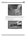
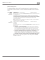
Installation Instructions
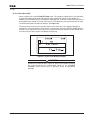
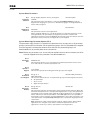
1. Strip the motor and input power cables as shown in Figure 3-1 and Table 3-14.
Ground
Ground
A1
C1
A2
C2
B1
D1
B2
D2
Power
Motor
Figure 3-1: Input Power and Motor Cable Stripping
and Wire Lengths
3-8
For more information visit: www.eaton.com
MN04001004E
9000X AF Drives User Manual
June 2009
Cable Stripping Lengths for Power and Motor Cables
Table 3-14: Power and Motor Cable Stripping Lengths
Product
Frame
Size
Power Wiring in Inches (mm)
Motor Wiring in Inches (mm)
A1
B1
C1
D1
A2
B2
C2
D2
hp
Voltage
3/4 – 3
1–5
230V
480V
FR4
0.59
(15)
1.38
(35)
0.39
(10)
0.79
(20)
0.28
(7)
1.97
(50)
0.28
(7)
1.38
(35)
5 – 7-1/2 230V
7-1/2 – 15 480V
FR5
0.79
(20)
1.57
(40)
0.39
(10)
1.18
(30)
0.79
(20)
2.36
(60)
0.39
(10)
1.57
(40)
10 – 15
20 – 30
2 – 25
230V
480V
575V
FR6
0.79
(20)
3.54
(90)
0.59
(15)
2.36
(60)
0.79
(20)
3.54
(90)
0.59
(15)
2.36
(60)
20 – 30
40 – 60
30 – 40
230V
480V
575V
FR7
0.98
(25)
4.72
(120)
0.98
(25)
4.72
(120)
0.98
(25)
4.72
(120)
0.98
(25)
4.72
(120)
75 – 125
50 – 75
480V
575V
FR8
1.10
(28)
9.45
(240)
1.10
(28)
9.45
(240)
1.10
(28)
9.45
(240)
1.10
(28)
9.45
(240)
150 – 200 480V
100 – 300 575V
FR9
1.10
(28)
11.61
(295)
1.10
(28)
11.61
(295)
1.10
(28)
11.61
(295)
1.10
(28)
11.61
(295)
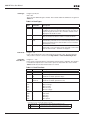
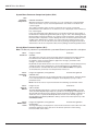
2. Locate the plastic bag containing the wiring plate.
Figure 3-2: Wiring Plate
3. If conduit is being used, attach the wiring plate to drive then conduit.
4. Pass the motor and input power wires/cables through the holes of the wiring plate.
5. Connect the input power and motor and control wires to their respective terminals
according to the wiring diagrams in the section marked “Standard Wiring Diagrams and
Terminal Locations” on Page 3-11.
6. If an optional external brake resistor is used, connect its cable to the appropriate
terminals. See “Standard Wiring Diagrams and Terminal Locations.”
7. If shielded cable is used, connect the shields of the input line power cable and the motor
cable to the ground terminals of the SVX9000/SPX9000 drive, the motor and the line
power supply.
MN04001004E
For more information visit: www.eaton.com
3-9
9000X AF Drives User Manual
June 2009
Figure 3-3: Ground Terminal Locations
8. If shielded cable is not used, check the connection of the ground cable to the motor, the
SVX9000/SPX9000 drive and the input line power terminals marked with
.
9. Attach the wiring plate with the screws provided. Ensure that no wires are trapped
between the frame and the wiring plate.
10. Insert the rubber grommets supplied into the wiring plate holes that have not been
used, as illustrated in Figure 3-4.
Figure 3-4: Cable Protection Plate
3-10
For more information visit: www.eaton.com
MN04001004E
9000X AF Drives User Manual
June 2009
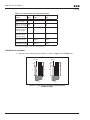
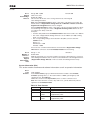
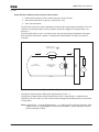
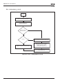
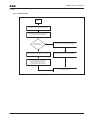
Standard Wiring Diagrams and Terminal Locations
The following wiring diagrams show the line and motor connections of the frequency
converter.
Power
Board
230V
480V
575V
3/4 - 15 hp
1 - 30 hp
2 - 25 hp
Control
Board
RFI Filter
L1
L2
L3
R- U
V
W
DC- DC+/
R+
Note:
Integrated Brake
Chopper Circuit Not
Included on 575V units.
BR
Option
L1 L2 L3
See
Note
M
3~
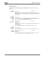
Figure 3-5: Principle Wiring Diagram of SVX9000/SPX9000 Power Unit,
FR4 to FR5 and FR6
Note: When using a 1-phase supply, for units rated for such, connect the input power to
terminals L1 and L2. Consult Eaton for more information.
MN04001004E
For more information visit: www.eaton.com
3-11
9000X AF Drives User Manual
June 2009
Power
Board
230V
480V
575V
20 - 30 hp
40 - 125 hp
30 - 75 hp
Control
Board
RFI Filter
L1
L2
L3
DC+/
R+
R- U
V
W
DCBR
Option
L1 L2 L3
See
Note
Note:
Integrated Brake
Chopper Circuit Not
Included on 575V units.
M
3~
Figure 3-6: Principle Wiring Diagram of SVX9000/SPX9000 Power Unit,
FR6, FR7 and FR8
Note: When using a 1-phase supply, for units rated for such, connect the input power to
terminals L1 and L2. Consult Eaton for more information.
3-12
For more information visit: www.eaton.com
MN04001004E
9000X AF Drives User Manual
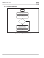
June 2009
Power
Board
480V
575V
150 - 350 hp
100 - 300 hp
Control
Board
RFI Filter
L1
L2
L3
DC+/
R+
R- U
V
W
DCBR
Option
L1 L2
See
Note
L3
M
3~
Figure 3-7: Principle Wiring Diagram of SVX9000/SPX9000 Power Unit,
FR9 to FR10
The dotted lines refer to components present in FR9 but not in FR10.
Note: When using a 1-phase supply, for units rated for such, connect the input power to
terminals L1 and L2. Consult Eaton for more information.
MN04001004E
For more information visit: www.eaton.com
3-13
9000X AF Drives User Manual
June 2009
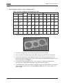
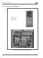
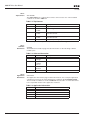
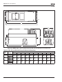
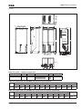
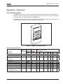
Power and Motor Wiring Terminal Photos
230V, 3/4 – 3 hp
480V, 1 – 5 hp
Frame Size: FR4
Figure 3-8: FR4 Power and Motor Wiring Terminals
3-14
For more information visit: www.eaton.com
MN04001004E
9000X AF Drives User Manual
June 2009
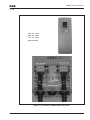
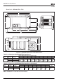
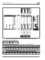
230V, 5 – 7-1/2 hp
480V, 7-1/2 – 15 hp
Frame Size: FR5
Figure 3-9: FR5 Power and Motor Wiring Terminals
MN04001004E
For more information visit: www.eaton.com
3-15
9000X AF Drives User Manual
June 2009
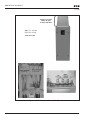
230V, 10 – 15 hp
480V, 20 – 30 hp
575V, 2 – 25 hp
Frame Size: FR6
Figure 3-10: FR6 Power and Motor Wiring Terminals
3-16
For more information visit: www.eaton.com
MN04001004E
9000X AF Drives User Manual
June 2009
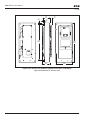
230V, 20 – 30 hp
480V, 40 – 60 hp
575V, 30 – 40 hp
Frame Size: FR7
Figure 3-11: FR7 Power and Motor Wiring Terminals
MN04001004E
For more information visit: www.eaton.com
3-17
9000X AF Drives User Manual
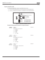
June 2009
Supplied only when
Brake Chopper
included with Drive.
{
480V, 75 – 125 hp
575V, 50 – 75 hp
Frame Size: FR8
Figure 3-12: FR8 Power and Motor Wiring Terminals
3-18
For more information visit: www.eaton.com
MN04001004E
9000X AF Drives User Manual
June 2009
480V, 150 – 200 hp
575V, 100 – 175 hp
Frame Size: FR9
Figure 3-13: FR9 Power and Motor Wiring Terminals
MN04001004E
For more information visit: www.eaton.com
3-19
9000X AF Drives User Manual
June 2009
Checking the Cable and Motor Insulation
1. Check the motor cable insulation as follows:
●
●
●
Disconnect the motor cable from terminals U, V and W of the SVX9000/SPX9000 and
from the motor.
Measure the insulation resistance of the motor cable between each phase conductor as
well as between each phase conductor and the protective ground conductor.
The insulation resistance must be >1 MΩ.
2. Check the input power cable insulation as follows:
●
●
●
Disconnect the input power cable from terminals L1, L2 and L3 of the SVX9000/
SPX9000 and from the utility line feeder.
Measure the insulation resistance of the input power cable between each phase
conductor as well as between each phase conductor and the protective ground
conductor.
The insulation resistance must be >1 MΩ.
3. Check the motor insulation as follows:
●
●
●
3-20
Disconnect the motor cable from the motor and open any bridging connections in the
motor connection box.
Measure the insulation resistance of each motor winding. The measurement voltage
must equal at least the motor nominal voltage but not exceed 1000V.
The insulation resistance must be >1 MΩ.
For more information visit: www.eaton.com
MN04001004E
9000X AF Drives User Manual
June 2009
Chapter 4 — Control Wiring
General Information
The control unit of the SVX9000/SPX9000 consists of the control board and various option
boards that plug into the five slot connectors (A to E) of the control board.
Galvanic isolation of the control terminals is provided as follows:
●
The control connections are isolated from power, and the GND terminals are
permanently connected to ground.
●
The digital inputs are galvanically isolated from the I/O ground.
●
The relay outputs are double-isolated from each other at 300V AC.
Option Board General Information
The SVX9000/SPX9000 series drives can accommodate a wide selection of expander and
adapter option boards to customize the drive for your application needs.
The drive’s control unit is designed to accept a total of five option boards. Option boards are
available for normal analog and digital inputs and outputs, communication and additional
application-specific hardware.
The SVX9000/SPX9000 factory installed standard option board configuration includes an A9
I/O board and an A2 relay output board, which are installed in slots A and B. For information
on additional option boards, see the 9000X Series Drives Option Board User Manual.
A
B
C
D
E
Figure 4-1: Option Board Slots
MN04001004E
For more information visit: www.eaton.com
4-1
9000X AF Drives User Manual
June 2009
Control Wiring Guidelines
Wire the control terminals using the following guidelines:
●
●
●
The control wires shall be at least AWG 20 (0.5 mm2) shielded cables.
The maximum wire size is AWG 14 (2.5 mm2) for the relay terminals and AWG 16
(1.5 mm2) for all other terminals.
The tightening torques for the option board terminals are listed in Table 4-1.
Table 4-1: Tightening Torques of Terminals
Tightening Torque
Terminal Screw
in-lbs
Nm
Relay and thermistor terminals
(M3 screw)
4.5
0.5
Other terminals (M2.6 screw)
2.2
0.25
Control Wiring Instructions
Table 4-2: Control Wiring Instructions
1. Unlock the bottom cover by turning
the locking screw 90 degrees
counterclockwise.
2. Remove the bottom cover by rotating
the cover towards you on the base
hinges, then lifting the cover away
from the base.
4-2
For more information visit: www.eaton.com
MN04001004E
9000X AF Drives User Manual
June 2009
Table 4-2: Control Wiring Instructions (Continued)
3. Wire the control terminals following
the details for the specific option
boards shown on the following pages.
Note: Note for ease of access, the option
board terminal blocks can be
unplugged for wiring.
Control Wiring Details
Wiring Option Board A9
Basic I/O Board A9
+10Vref
1
AI1+
2
GND
3
AI2+
4
AI2-
5
24Vout
6
GND
7
DIN1
8
DIN2
9
DIN3
10
CMA
11
Input Reference
(Voltage)
Input Reference
(Current)
Control Voltage Output
24V
GND
24Vout 12
GND
13
DIN4
14
DIN5
15
DIN6
16
CMB
17
AO1+
18
0 (4)/20 mA
AO1-
19
RL<500 8
DO1
20
+ V<+48V
I<50 mA
24V
GND
Indicates Connections for Inverted Signals
Figure 4-2: Option Board A9 Wiring Diagram
MN04001004E
For more information visit: www.eaton.com
4-3
9000X AF Drives User Manual
June 2009
Table 4-3: Option Board A9 Terminal Descriptions
4-4
Terminal
Signal
Description and Parameter Reference
1
+10 Vref
Reference voltage
Maximum current 10 mA
2
AI1+
Analog input, voltage
3
GND
Analog input common
Default: 0 – +10V (Ri = 200 kΩ)
-10V to +10V (joystick control)
0 – 20 mA (Ri = 250 Ω)
Select V or mA with jumper block X1 (Figure 4-3)
Differential input if not connected to ground;
allows ±20V differential mode voltage to GND
4
AI2+
Analog input
5
GND/AI2- Analog input common
6
24 Vout
24V control voltage (bi-directional)
±15%, 250 mA (all boards total); 150 mA (max.
current from single board); Can be used as
external power backup for the control (and
fieldbus); Galvanically connected to terminal #12
7
GND
I/O ground
Ground for reference and controls; Galvanically
connected to terminals #13, 19
Ri = min. 5 kΩ
Default: 0 – 20 mA (Ri = 250 Ω)
0 – +10V (Ri = 200 kΩ)
-10V to +10V (joystick control)
Select V or mA with jumper block X2
(Figure 4-3)
Differential input if not connected to ground;
allows ±20V differential mode voltage to GND
8
DIA1
Digital input 1
9
DIA2
Digital input 2
10
DIA3
Digital input 3
11
CMA
Digital input common A for DIN1,
DIN2 and DIN3
Must be connected to GND or 24V of I/O terminal
or to external 24V or GND. Selection with
jumper block X3. (Figure 4-3)
12
24 Vout
24V control voltage (bi-directional)
Same as terminal #6; Galvanically connected to
terminal #6
13
GND
I/O ground
Same as terminal #7; Galvanically connected to
terminals #7 & 19
14
DIB4
Digital input 4
Ri = min. 5 kΩ
15
DIB5
Digital input 5
16
DIB6
Digital input 6
17
CMB
Digital input common B for DIN4,
DIN5 and DIN6
Must be connected to GND or 24V of I/O terminal
or to external 24V or GND. Select with jumper
block X3. (Figure 4-3)
18
A01+
Analog signal (+output)
Output signal range: 0 – 10V default
Current: 0(4) – 20 mA, RL max 500 Ω or
Voltage: 0 – 10V, RL >1 kΩ
Selection with jumper block X6. (Figure 4-3)
19
A01-
Analog output common
Maximum Vin = 48V DC; Galvanically connected
to terminals #7, 13
20
DO1
Digital output1
Open collector, Maximum current = 50 mA
For more information visit: www.eaton.com
MN04001004E
9000X AF Drives User Manual
June 2009
X2 Jumper Setting
Analog Input 2 (AI2)
X1 Jumper Setting
Analog Input 1 (AI1)
0 to 20 mA* A B C D
Current Input
ABC D
0 to 10V*
Voltage Input
ABC D
0 to 10V
Voltage Input
ABC D
0 to 20 mA
Current Input
0 to 10V
ABC D
(Differential)
Voltage Input
0 to 10V
ABC D
(Differential)
Voltage Input
X6 Jumper Setting
Analog Output 1 (A01)
ABC D
0 to 20 mA
Current Output
ABC D
-10 to 10V
Voltage Input
ABC D
0 to 10V*
Voltage Output
ABC D
-10 to 10V
Voltage Input
ABC D ABC D
X1
X2
ABC D
X6
X3 Jumper Setting
CMA and CMB Grounding
CMB Connected to Ground*
CMA Connected to Ground
X3
CMB Isolated from Ground
CMA Isolated from Ground
CMB and CMA Internally
Connected and Isolated
from Ground
* Designates Default Jumper Settings
Figure 4-3: Option Board A9 Jumper Location and Settings
Wiring Option Board A2
Basic Relay Board A2
RO1/1
21
RO1/2
22
RO1/3
23
RO2/1
24
RO2/2
25
RO2/3
26
RL
AC / DC
Switching:
<8A / 24V DC
<0.4A / 125V DC
<8A / 250V AC
Continuously
<2 Arms
Figure 4-4: Option Board A2 Wiring Diagram
MN04001004E
For more information visit: www.eaton.com
4-5
9000X AF Drives User Manual
June 2009
Table 4-4: Option Board A2 Terminal Descriptions
Terminal
Signal
Technical Information
Switching Capacity:
24V DC / 8A
250V AC / 8A
125V DC / 0.4A
Min Switching Load: 5V/10 mA
Continuous Capacity: <2 Arms
21
RO1/1
Normally Closed (NC)
22
RO1/2
Common
23
RO1/3
Normally Open (NO)
24
RO2/1
Normally Closed (NC)
25
RO2/2
Common
26
RO2/3
Normally Open (NO)
Switching Capacity:
24V DC / 8A
250V AC / 8A
125V DC / 0.4A
Min Switching Load: 5V/10 mA
Continuous Capacity: <2 Arms
21 22 23
24 25 26
Figure 4-5: Option Board A2 Terminal Locations
Inverting the Digital Input Signal
The active signal level depends on which potential the common inputs CMA and CMB
(terminals 11 and 17) are connected to. The alternatives are either +24V or ground (0V). See
Figure 4-6.
The 24V control voltage and the ground for the digital inputs and the common inputs (CMA,
CMB) can be sourced from either the internal 24V supply or an external supply.
1
2
+24V
Ground
Ground
DIN1
DIN1
DIN2
DIN2
DIN3
DIN3
CMA
+24V
CMA
Figure 4-6: Positive/Negative Logic
4-6
Positive logic (+24V is the active signal) = the input is active when the switch is closed.
Negative logic (0V is the active signal) = the input is active when the switch is closed.
For more information visit: www.eaton.com
MN04001004E
9000X AF Drives User Manual
June 2009
Chapter 5 — Menu Information
Keypad Operation
Figure 5-1: Keypad and Display
Table 5-1: LCD Status Indicators
Indicator
Description
Run
Indicates that the SVX9000/SPX9000 is running and controlling the load.
Blinks when a stop command has been given but the SVX9000/SPX9000 is
still ramping down.
Counterclockwise Operation
The output phase rotation is BAC, corresponding to counterclockwise
rotation of most motors.
Clockwise Operation
The output phase rotation is ABC, corresponding to clockwise rotation of
most motors.
Stop
Indicates that the SVX9000/SPX9000 is stopped and not controlling the load.
Ready
Indicates that the SVX9000/SPX9000 is ready to be started.
Alarm
Indicates that there is one or more active drive alarm(s).
Fault
Indicates that there is one or more active drive fault(s).
I/O Terminal
Indicates that the I/O terminals have been chosen for control.
Keypad
Indicates that the keypad has been chosen for control.
Bus/Communications
Indicates that the communications bus control has been chosen for control.
MN04001004E
For more information visit: www.eaton.com
5-1
9000X AF Drives User Manual
June 2009
Table 5-2: LED Status Indicators
Indicator
Description
local
Local — Steady Illumination
Indicates that the SVX9000/SPX9000 is ready to be started and operated from
the Local mode.
Local — Flashing
Indicates that the SVX9000/SPX9000 is ready for operating command to
select Local or Remote operation.
remote
Remote
Indicates that the SVX9000/SPX9000 is operating and controlling the load
remotely.
fault
Fault
Indicates that there is one or more active drive fault(s).
Table 5-3: Navigation Buttons
Button
Description
Start
This button operates as the START button for normal operation when the
“Keypad” is selected as the active control.
Enter
This button is used in the parameter edit mode to save the parameter setting
and move to the next parameter …
• to reset the Fault History if pressed while in the “Fault History” menu.
• to confirm the acceptance of a change.
• to change a virtual button status while in the “Button” menu.
• to confirm the start-up list at the end of the Start-Up Wizard.
• when the “Operate” menu is active, to exit the “Operate” submenu.
Stop
This button has two integrated operations. The button operates as STOP
button during normal operation …
• motor STOP from the keypad, which is always active unless disabled by
the “StopButtonActive” parameter.
• used to reset the active faults.
Reset
Resets the active faults.
Local / Remote
Switches between LOCAL and REMOTE control for start, speed reference and
reverse functions. The control locations corresponding to local and remote
can be selected within an application.
5-2
For more information visit: www.eaton.com
MN04001004E
9000X AF Drives User Manual
June 2009
Table 5-3: Navigation Buttons (Continued)
Button
Description
Left Arrow
• navigation button, movement to left.
• in parameter edit mode, exits mode, backs up one step.
• cancels edited parameter (exit from a parameter edit mode).
• When in “Operate” menu will move backward through menu.
• At end of “Start-Up Wizard”, repeats the “Start-Up Wizard” setup menu.
Right Arrow
• navigation button, movement to right.
• enter parameter group mode.
• enter parameter mode from group mode.
• When in “Operate” menu will move forward through menu.
Up and Down Arrows
• move either up or down a menu list to select the desired menu item.
• editing a parameter/password, while the active digit/character is scrolled.
• increase/decrease the reference value of the selected parameter.
• in the “Operate” menu, will cause the display of the current reference
source and value and allow its change if the keypad is the active
reference source. Used to set the password (if defined) when leaving
the “Operate” menu.
• scroll through the “Active Faults” menu when the SVX9000/SPX9000 is
stopped.
Menu Navigation
Navigation Tips
●
To navigate within one level of a menu, use the up and down arrows.
●
To move deeper into the menu structure and back out, use the right and left arrows.
●
●
●
●
●
To edit a parameter, navigate to show that parameter’s value, and press the right arrow
button to enter the edit mode. In edit mode, the parameter value will flash.
When in edit mode, the parameter value can be changed by pressing the up or down
arrow keys.
When in edit mode, pressing the right arrow a second time will allow you to edit the
parameter value digit by digit.
To confirm the parameter change you must press the ENTER button. The value will not
change unless the ENTER button is pushed.
Some parameters can not be changed while the SVX9000/SPX9000 is running. The
screen will display LOCKED if you attempt to edit these parameters while the drive is
running. Stop the drive to edit these parameters. See the appropriate application
manual for identification of these parameters specific to your chosen application.
Main Menu
The data on the control keypad are arranged in menus and submenus. The first menu level
consists of M1 to M8 and is called the Main Menu. The structure of these menus and their
submenus is illustrated in Figure 5-2. Some of the submenus will vary for each application
choice.
MN04001004E
For more information visit: www.eaton.com
5-3
9000X AF Drives User Manual
June 2009
+ M1 Parameters
G1.1
...
G1.x
+ M2 Keypad Control
R2.1 Keypad Reference
P2.2 Keypad Direction
...
P2.x Stop Button Active
+ M3 Active Faults
A3.1 Active Fault 1
T3.1.1 Operation Days
...
T3.1.13 Zero Speed
...
A3.x Active Fault x
Menu Navigation:
Up Arrow — The up arrow
advances to the next
menu item.
For example, pressing the
up arrow once will
advance from M1 to M2.
Down Arrow — The down
arrow backs up to the
previous menu item.
For example, pressing the
down arrow once will back
up from M2 to M1.
Right Arrow — The right
arrow will advance to the
next level in the menu.
For example, pressing the
right arrow once will
advance from M2 to R2.1.
Left Arrow — The left
arrow will back up one
level in the menu
structure.
For example, pressing the
left arrow once will back
up from R2.1 to M2.
+ M4 Fault History
H4.1 Most Recent Fault
T4.1.1 Operation Days
...
T4.1.13 Zero Speed
...
H4.1.x Oldest Saved Fault
+ M5 System Menu
S5.1
S5.2
S5.3
S5.4
S5.5
S5.6
S5.7
S5.8
Language
Application
Copy Parameters
Compare Parameters
Security
Keypad Settings
Hardware Settings
System Information
+ M6 Expander Boards
G6.1 Slot A Board
...
G6.5 Slot E Board
+ M7 Monitor
V7.1 Output Frequency - 0.00 Hz
V7.2 Frequency Reference - 0.00 Hz
...
M7.1x Multimonitor
N7.1x.1
+ M8 Operate Mode
O1 Output Frequency - 0.0 Hz
O2 Freq Reference - 0.0 Hz
...
Ox . . .
Figure 5-2: Main Menu Navigation
5-4
Menu application dependent.
For more information visit: www.eaton.com
MN04001004E
9000X AF Drives User Manual
June 2009
Parameter Menu (M1)
The Parameter Menu is a single or multi-level menu dependent upon the application in use,
arranged by the parameter group items. Figure 5-3 illustrates this for the Standard
application. Parameters and parameter groups are explained in further detail in the
appropriate application manual.
M1 Parameters Menu
+ G1.1 Basic Parameters
P1.1.1 Minimum Frequency
P1.1.2 Maximum Frequency
...
P1.1.16 Preset Speed 1
+ G1.2 Input Signals
P1.2.1 Start/Stop Logic
P1.2.2 DIN3 Function
...
P1.2.9 AI2 Signal Select
+ G1.3 Output Signals
P1.3.1 A1out Signal
P1.3.2 A1out Content
...
P1.3.17 A2out Scale
+ G1.4 Drive Control
P1.4.1 Ramp 1 Shape
P1.4.2 Ramp 2 Shape
...
P1.4.13 Flux Brake Current
+ G1.5 Skip Frequency
P1.5.1 Skip F1 Low Limit
P1.5.2 Skip F1 High Limit
P1.5.3 PH Accel/Decel Ramp
+ G1.6 Motor Control
P1.6.1 Motor Control Mode
P1.6.2 V/Hz Optimization
...
P1.6.13 Identification
+ G1.7 Protections
P1.7.1 4mA Input Fault
P1.7.2 4mA Fault Frequency
...
P1.7.23 Slot Comm Fault Response
+ G1.8 Auto Restart
P1.8.1 Wait Time
P1.8.2 Trial Time
...
P1.8.10 Underload Tries
Figure 5-3: Parameter Menu Structure Example
MN04001004E
For more information visit: www.eaton.com
5-5
9000X AF Drives User Manual
June 2009
Keypad Control Menu (M2)
In the Keypad Control Menu, you can set the frequency reference, choose the motor
direction for keypad operation, and determine if the STOP button will be active at all
times. See Figure 5-4.
M2 Keypad Control
R2.1 Keypad Reference
P2.2 Keypad Direction
...
P2.x Stop Button Active
Figure 5-4: Keypad Control Menu
5-6
R2.1
Keypad
Reference
Range: Min. Frequency — Max. Frequency
Units: Hertz
Keypad Reference
This displays and allows the operator to edit the keypad frequency reference. A
change takes place immediately. This reference value will not influence the output
frequency unless the keypad has been selected as the active control place.
P2.2
Keypad
Direction
Range: Forward, Reverse
Default: Forward
Keypad Direction
This allows the operator to change the rotation direction of the motor. This setting
will not influence the rotation direction of the motor unless the keypad has been
selected as the active control place.
P2.3 Stop Button
Active
Range: Yes, No
Default: Yes
StopButtonActive
By default, pushing the STOP button will always stop the motor regardless of the
selected control place. If this parameter is set to No, the STOP button will stop the
motor only when the keypad has been selected as the active control place.
This parameter number varies for different applications.
For more information visit: www.eaton.com
MN04001004E
9000X AF Drives User Manual
June 2009
Active Faults Menu (M3)
When a fault occurs, the SVX9000/SPX9000 stops. The sequence indication F1, the fault code,
a short description of the fault and the fault type symbol will appear on the display. In
addition, the indication FAULT or ALARM is displayed and, in case of a FAULT, the red LED on
the keypad starts to blink. If several faults occur simultaneously, the sequence of active faults
can be browsed with the Browser buttons. See Figure 5-5.
The active faults memory can store the maximum of 10 faults in the sequential order of
appearance. The fault remains active until it is cleared with either the STOP or RESET buttons
or with a reset signal from the I/O terminal. Upon fault reset the display will be cleared and
will return to the same state it was before the fault trip.
51
F
Ext Fault
T1
T13
Figure 5-5: Active Fault Display Example
CAUTION
Remove any External Start signals or permissives before resetting
the fault to prevent an unintentional restart of the SVX9000/
SPX9000, which could result in personal injury or equipment
damage.
MN04001004E
For more information visit: www.eaton.com
5-7
9000X AF Drives User Manual
June 2009
Fault Type
Range: A, F, AR, FT
Fault Type
There are four different types of faults. These faults and their definitions are given in
Table 5-4.
Table 5-4: Fault Types
Fault Code
Fault Time
Data Record
Fault
Type
Fault Name
Description
A
Alarm
This type of fault is a sign of an unusual operating
condition. It does not cause the drive to stop, nor does it
require any special actions. The “A fault” remains in the
display for about 30 seconds.
F
Fault
An “F fault” is a kind of fault that makes the drive stop.
Actions need to be taken in order to restart the drive.
AR
Auto-Restart
Fault
If an “AR fault” occurs the drive will also stop
immediately. The fault is reset automatically and the drive
tries to restart the motor. If the restart is not successful, a
fault trip (FT) occurs.
FT
Fault Trip
If the drive is unable to restart the motor after an AR fault,
an FT fault occurs. The effect of the “FT fault” is the same
as that of the F fault — the drive is stopped.
Range: 1 – 54
Fault codes indicate the cause of the fault. A list of fault codes, their descriptions,
and possible solutions can be found in Appendix B — Fault and Warning Codes.
Range: T.1 – T.13
In this menu, important data recorded at the time the fault is available. This feature
is intended to help the user or the service person to determine the cause of fault.
Table 5-5 indicates the information that is recorded.
Table 5-5: Fault Time Data
Data
Units
Description
T.1 D
Counted operation days (Fault 43: Additional code)
T.2
hh:mm:ss
(d)
Counted operation hours
(Fault 43: Counted operation days)
T.3
Hz
hh:mm:ss
Output frequency
(Fault 43: Counted operation hours)
T.4
T.5
T.6
T.7
T.8
A
V
%
%
V
Motor current
Motor voltage
Motor power
Motor torque
DC bus voltage
T.9
T.10
T.11
T.12
T.13
°C
—
—
—
—
Unit temperature
Run status
Direction
Warnings
Zero speed
Real time record.
If real time is set, T.1 and T.2 will appear as follows:
5-8
T.1
yyyy-mm-dd
Counted operation days (Fault 43: Additional code)
T.2
hh:mm:ss.sss
Counted operation hours (Fault 43: Counted operation days)
For more information visit: www.eaton.com
MN04001004E
9000X AF Drives User Manual
June 2009
Fault History Menu (M4)
All faults are stored in the Fault History Menu, which can be viewed by using the Browser
buttons. Additionally, the Fault time data record pages are accessible for each fault as in the
Active Faults Menu described above. See Figure 5-6.
The SVX9000/SPX9000’s memory can store a maximum of 30 faults, in the order of
appearance. If there are 30 uncleared faults in the memory, the next occurring fault will erase
the oldest fault from the memory.
11
F
Output Phase
T1
T13
Figure 5-6: Sample Fault History Display
Note: Pressing the ENTER button for 3 seconds will clear the entire fault history.
MN04001004E
For more information visit: www.eaton.com
5-9
9000X AF Drives User Manual
June 2009
System Menu (M5)
The controls associated with the general use of the drive, such as application selection,
customized parameter sets or information about the hardware and software are located in
the System Menu. Password protection can be activated by parameter S5.5.1.
Descriptions of the system menu parameters are illustrated in Figure 5-7.
+ S5.1 Language Selection
+ S5.2 Application Selection
+ S5.3 Copy Parameters
S5.3.1
S5.3.2
S5.3.3
S5.3.4
Parameter Sets
Upload to Keypad
Download from Keypad
Automate Backup
S5.4 Parameter Comparison
+ S5.5 Security
S5.5.1
P5.5.2
P5.5.3
P5.5.4
Password
Parameter Lock
Start-Up Wizard
Multimonitor Items
+ S5.6 Keypad Settings
P5.6.1
P5.6.2
P5.6.3
P5.6.4
P5.6.5
Default Page
Default Page/Operating Menu
Timeout Time
Contrast Adjustment
Backlight Time
+ S5.7 Hardware Settings
P5.7.1
P5.7.2
P5.7.3
P5.7.4
Internal Brake Resistor
Fan Control
HMI Acknowledge Timeout
HMI Number of Retries
+ S5.8 System Information
+
+
+
+
+
+
+
S5.8.1 Total Counters
C5.8.1.1 MWh Counter
C5.8.1.2 Power On Day Counter
C5.8.1.3 Power On Hour Counter
S5.8.2 Trip Counters
T5.8.2.1 MWh Counter
T5.8.2.2 Clear MWh Trip Counter
T5.8.2.3 Power On Day Counter
T5.8.2.4 Power On Hour Counter
T5.8.2.5 Clear Operating Time Counter
S5.8.3 Software Information
I5.8.3.1 Software Package
I5.8.3.2 System Software Version
I5.8.3.3 Firmware Interface
I5.8.3.4 System Load
S5.8.4 Applications
A5.8.4.# Name of Application
D5.8.4.#.1 Application ID
D5.8.4.#.2 Version
D5.8.4.#.3 Firmware Interface
S5.8.5 Hardware
I5.8.5.1 Nominal Unit Power
I5.8.5.2 Nominal Unit Voltage
E5.8.5.3 Brake Chopper
E5.8.5.4 Brake Resistor
S5.8.6 Expander Boards
S5.8.7 Debug Menu
Figure 5-7: System Menu Structure
5-10
For more information visit: www.eaton.com
MN04001004E
9000X AF Drives User Manual
June 2009
System Menu Parameters
S5.1
Language
Selection
S5.2
Application
Selection
Range: English, Spanish, French, Portuguese
Default: English
Language
This parameter offers the ability to control the SVX9000/SPX9000 through the
keypad in the language of your choice. Available languages are: English, Spanish,
French and Portuguese.
Default: Basic
Application
This parameter sets the active application.
When changing applications, you will be asked if you want the parameters of the
new application to be uploaded to the keypad. If you wish to load the new
application parameters, push the ENTER button. Pushing any other button saves the
parameters of the previously used application in the keypad.
System Menu Copy Parameter Options (S5.3)
The parameter copy function is used when the operator wants to copy one or all parameter
groups from one drive to another. All the parameter groups are first uploaded to the keypad,
then the keypad is connected to another drive and then the parameter groups are
downloaded to it (or possibly back to the same drive).
Note: Before any parameters can successfully be copied from one drive to another, the drive
must be stopped when the parameters are downloaded to it.
S5.3.1
Parameter
Sets
S5.3.2
Upload to
Keypad
S5.3.3
Download
from Keypad
S5.3.4
Automatic
Backup
MN04001004E
Parameter Sets
This parameter allows you to reload the factory default parameter values, and to
store and load two customized parameter sets.
Up to keypad
This function uploads all existing parameter groups to the keypad.
Range: 0 – 3
Default: 0 (All parameters)
Down from keypad
This function downloads one or all parameter groups from the keypad to the drive.
0 All parameters
1 All, no motor
2 Application parameters
Range: Yes, No
Default: Yes
Auto.backup
This parameter activates and deactivates the parameter backup function. When the
Parameter backup function is activated, the keypad makes a copy of the parameters
and settings in the currently active application. When applications are changed, you
will be asked if you wish the parameters of the new application to be uploaded to
the keypad. For this to happen, push the ENTER button. If you wish to keep the copy
of the parameters of the previously used application saved in the keypad push any
other button.
Note: Parameters saved in the parameter settings of S5.3.1 will be deleted when
applications are changed. If you want to transfer the parameters from one
application to another you have to upload them to the keypad first.
For more information visit: www.eaton.com
5-11
9000X AF Drives User Manual
June 2009
System Menu Parameter Comparison Options (S5.4)
S5.4
Parameter
Comparison
Parameter Comparison
With the Parameter Comparison function, you can compare the actual parameter
values to the values of your customized parameter sets and those loaded to the
control keypad.
The actual parameter values are first compared to those of the customized
parameter Set1. If no differences are detected, a “0” is displayed on the lowermost
line of the keypad.
If any of the parameter values differ from those of the Set1 parameters, the number of
the deviations is displayed together with symbol P (e.g. P1 ➔ P5 = five deviating values).
By pressing the right arrow button once again you will see both the actual value and
the value it was compared to. In this display, the value on the Description line (in the
middle) is the default value, and the one on the value line (lowermost line) is the
edited value. You can also edit the actual value by pushing the Right Arrow button.
Actual values can also be compared to Set2, Factory Settings and the Keypad Set values.
Security Menu Parameter Options (S5.5)
Note: The Security submenu is protected with a password. Store the password in a safe place.
S5.5.1
Password
Range: 0 – 65535
Default: 0
Password
The application selection can be protected against unauthorized changes with the
Password function. When the password function is enabled, the user will be
prompted to enter a password before application changes, parameter value
changes, or password changes.
By default, the password function is not in use. If you want to activate the password,
change the value of this parameter to any number between 1 and 65535. The
password will be activated after the Timeout time (Timeout Time) has expired.
To deactivate the password, reset the parameter value to 0.
P5.5.2
Parameter
Lock
Range: ChangeEnable, ChangeDisabl
Default: ChangeDisabl
Parameter Lock
This function allows the user to prohibit changes to the parameters. If the parameter
lock is activated the text *locked* will appear on the display if you try to edit a
parameter value.
Note: This function does not prevent unauthorized editing of parameter values.
P5.5.3
Start-Up
Wizard
P5.5.4
Multimonitor
Items
5-12
Range: Yes, No
Default: No
Start-up Wizard
The Start-Up Wizard facilitates commissioning the SVX9000/SPX9000. If selected
active, the Start-Up Wizard prompts the operator for the language and application
desired and then advances through the start-up parameter list. After completion it
allows the user to repeat the Start-Up Wizard or return to the default page, the
Operate Menu. The Start-Up Wizard in always active for the initial power up of the
SVX9000/SPX9000.
Range: ChangeEnable, ChangeDisabl
Default: ChangeEnable
Multimon.items
The keypad display can display three actual monitored values at the same time. This
parameter determines if the operator is allowed to replace the values being
monitored with other values.
For more information visit: www.eaton.com
MN04001004E
9000X AF Drives User Manual
June 2009
Keypad Settings (S5.6)
There are five parameters (Default Page to Backlight Time) associated with the keypad
operation:
P5.6.1
Default Page
P5.6.2
Default Page
in the
Operating
Menu
P5.6.3
Timeout Time
P5.6.4
Contrast
Adjustment
P5.6.5
Backlight
Time
MN04001004E
Default: 0
Default page
This parameter sets the view to which the display automatically moves as the
Timeout Time expires or when the keypad power is switched on. If the Default Page
value is 0 this function is not activated, i.e. the last displayed page remains on the
keypad display.
Default page/OM
Here you can set the location in the Operating menu to which the display
automatically moves as the set Timeout Time expires, or when the keypad power is
switched on. See setting of Default Page parameter above.
Range: 0 – 65,535
Default: 30
Units: Seconds
Timeout time
The Timeout Time setting defines the time after which the keypad display returns to
the Default Page.
Note: If the Default Page value is 0 the Timeout Time setting has no effect.
Contrast adjustment
If the display is not clear, you can adjust the keypad contrast with this parameter.
Range: 1 – 65,535 or Forever
Default: 10
Units: Minutes
Backlight time
This parameter determines how long the backlight stays on before going out. You
can select any time between 1 and 65,535 minutes or “Forever”.
For more information visit: www.eaton.com
5-13
9000X AF Drives User Manual
June 2009
Hardware Settings (S5.7)
The Hardware Settings submenu (S5.7) provides parameters for setting information on
Internal brake resistor connection, Fan control, Keypad acknowledge timeout and Keypad
retries.
5-14
P5.7.1
Internal Brake
Resistor
Connection
Range: Connected – Not Connected
Default: Connected
Internbrakeres
With this function you tell the SVX9000/SPX9000 whether the internal brake resistor
is connected or not.
If your drive has an internal brake resistor, the default value of this parameter is
“Connected”. However, if it is necessary to increase braking capacity by installing an
external brake resistor, or if the internal brake resistor is disconnected, it is advisable
to change the value of this function to “Not Connected” in order to avoid
unnecessary fault trips.
Note: The brake resistor is available as an option for all drives. It can be installed
internally in frame sizes FR4 to FR6.
5.7.2
Fan Control
Range: Continuous, Temperature, First Start and
Default: Continuous
Calc Temp
Fan Control
This function allows you to control the SVX9000/SPX9000’s cooling fan. You can set
the fan to run:
1 Continuous — fan runs continuously.
2 Temperature — based on the temperature of the unit. The fan is switched on
automatically when the heatsink temperature reaches 60°C. The fan receives a
stop command when the heatsink temperture falls to 55°C. The fan runs for
about a minute after receiving the stop command or switching on the power, as
well as after changing the value from “Continuous” to “Temperature”.
3 First Start — after power up the fan is stopped until the run command is given
and then fan runs continuously. This is mainly made for common DC-bus
systems to prevent cooling fans to load charging resistors on power up moment.
4 Calc Temp — starting of cooling fan is based on calculated IGBT-temperature.
When IGBT temp = 40°C, fan starts and when temp falls down to 30°C, fan stops.
Note: The fan runs continuously, regardless of this setting, when the SVX9000/
SPX9000 is in RUN state.
For more information visit: www.eaton.com
MN04001004E
9000X AF Drives User Manual
June 2009
P5.7.3
Keypad
Acknowledge
Timeout
Range: 200 – 5,000
Default: 200
Units: mseconds
Keypad ACK timeout
This function allows the user to change the timeout of the Keypad
acknowledgement time.
Note: If the SVX9000/SPX9000 has been connected to a PC with a serial cable, the
default values of Keypad Acknowledge Timeout and Number of Retries to Receive
Keypad Acknowledgement must not be changed.
If the SVX9000/SPX9000 has been connected to a PC via a modem and there is delay
in transferring messages, the value of Keypad Acknowledge Timeout must be set
according to the delay as follows:
Example:
• Transfer delay between the SVX9000/SPX9000 and the PC is found to be = 600 ms
• The value of Keypad Acknowledge Timeout is set to 1200 ms (2 x 600, sending
delay + receiving delay)
• The corresponding setting is then entered in the [Misc] section of the file
9000XDrive.ini:
Retries = 5
AckTimeOut = 1200
TimeOut = 5000
It must also be considered that intervals shorter than the Keypad Acknowledge
Timeout time cannot be used in SVX9000/SPX9000 drive monitoring.
P5.7.4
Number of
Retries to
Receive
Keypad
Acknowledgement
Range: 1 – 10
Default: 5
Keypad retry
With this parameter you can set the number of times the drive will try to receive an
acknowledgement when it has not been received within the acknowledgement time
(Keypad Acknowledge Timeout) or if the received acknowledgement is faulty.
System Information (S5.8)
This section contains hardware and software information as well as operation information.
S5.8.1
Total
Counters
Total counters
In the Total Counters page you will find information related to the SVX9000/
SPX9000 operating times, i.e. the total numbers of MWh, operating days and
operating hours. See Table 5-6.
Unlike the counters for the Trip Counters, these counters cannot be reset.
Note: The Power On time counters, days and hours, operate whenever power is
applied to the SVX9000/SPX9000.
Table 5-6: Total Counters
MN04001004E
Number
Name
Description
C5.8.1.1
MWh counter
Megawatt hours total operation time counter
C5.8.1.2
Power On day
counter
Number of days the SVX9000/SPX9000 has been
supplied with power
C5.8.1.3
Power On hour Number of hours the SVX9000/SPX9000 has been
counter
supplied with power
For more information visit: www.eaton.com
5-15
9000X AF Drives User Manual
June 2009
S5.8.2
Trip Counters
Trip counters
The Trip Counters are counters whose values can be reset to zero. The resettable
counters are shown in Table 5-7.
Table 5-7: Trip Counters
Number
Name
Description
T5.8.2.1
MWh counter
Megawatts hours since last reset
P5.8.2.2
Clear MWh
counter
Resets megawatts hours counter
T5.8.2.3
Power On day
counter
Number of days the SVX9000/SPX9000 has been run
since the last reset
T5.8.2.4
Power On hour Number of hours the SVX9000/SPX9000 has been run
counter
since the last reset
P5.8.2.5
Clr Optime cntr Resets the operating day and hour counters
Note: The Trip Counters operate only when the motor is running.
S5.8.3
Software
Information
Software
The Software information page includes information on the following software
related topics:
Table 5-8: Software Information
S5.8.4
Application
Information
Number
Name
Description
I5.8.3.1
Software
package
SVX00031V003
I5.8.3.2
System
software
version
11.53.6536
I5.8.3.3
Firmware
interface
4.37
I5.8.3.4
System load
G9.1
Applications
The Application information page includes information on not only the application
currently in use but also all other applications loaded into the SVX9000/SPX9000.
The information available is shown in Table 5-9. Note that the “x” in the table refers
to the sequential number of the application in the list.
Table 5-9: Application Information
5-16
Name
Content
A4.8.4.x
Application name
D4.8.4.x.1
Application ID
D4.8.4.x.2
Version
D4.8.4.x.3
Firmware interface
For more information visit: www.eaton.com
MN04001004E
9000X AF Drives User Manual
June 2009
S5.8.5
Hardware
Information
Hardware
The Hardware information page provides information on the following hardwarerelated topics:
Table 5-10: Hardware Information
S5.8.6
Expander
Board
Information
Number
Content
I5.8.5.1
Nominal power of the unit
I5.8.5.2
Nominal voltage of the unit
E5.8.5.3
Brake chopper
E5.8.5.4
Brake resistor
Expander boards
This parameter and its sub-items provide information about the basic and option
boards plugged into the control board as shown in Table 5-11. Note that the “x” in
the table refers to the sequential number of the slot, with slot A being “1” and slot
E being “5”.
Table 5-11: Expander Board Information
S5.8.7
Debug Menu
MN04001004E
Number
Content
E5.8.6.x
Slot “x” board identification
E5.8.6.x.1
Operating state
E5.8.6.x.2
Software version
Debug
This menu is meant for advanced users and application designers. Contact the
factory for any assistance needed.
For more information visit: www.eaton.com
5-17
9000X AF Drives User Manual
June 2009
Expander Board Menu (M6)
The Expander Board Menu makes it possible for the user to:
●
to see what expander boards are connected to the control board and
●
to access and edit the parameters associated with the expander board.
+ G6.1 “A: OPTA9” (Slot A Option Board)
G6.1.1 Parameters
P6.1.1.1 AI1 Mode
P6.1.1.2 AI2 Mode
P6.1.1.3 AO1 Mode
G6.1.2 I/O-monitor
+
+
+
+
G6.2
G6.3
G6.4
G6.5
“B:
“C:
“D:
“E:
” (Slot B Option Board)
” (Slot C Option Board)
” (Slot D Option Board)
” (Slot E Option Board)
Figure 5-8: Expander Board Menu Structure
Example of Expander Board Parameters for Option Board A9
P6.1.1.1
AI1 Mode
Range: 1 – 5
AI1 Mode
Analog Input 1 input options:
1 0 – 20 mA
2 4 – 20 mA
3 0 – 10V
4 2 – 10V
5 -10 – +10VP
Default: 3
P6.1.1.2
AI2 Mode
Range: 1 – 5
AI2 Mode
Analog Input 2 input options:
1 0 – 20 mA
2 4 – 20 mA
3 0 – 10V
4 2 – 10V
5 -10 – +10VP
Default: 1
Range: 1 – 4
A01 Mode
Analog Output 1 output options:
1 0 – 20 mA
2 4 – 20 mA
3 0 – 10V
4 2 – 10V
Default: 1
P6.1.1.3
AO1 Mode
5-18
For more information visit: www.eaton.com
MN04001004E
9000X AF Drives User Manual
June 2009
Monitoring Menu (M7)
The Monitoring Menu items are meant for viewing parameter values during operation.
Monitored values are updated every 0.3 sec. Monitored items are identified by item numbers
V7.1 to V1.xx, where “xx” varies by application. Table 5-12 provides an example of the
monitored values for the Standard application.
Monitored parameters are not editable from this menu (See Parameter Menu [M1] to change
parameter values).
Table 5-12: Monitoring Menu Items — Standard Application Example
Code
Signal Name
Unit
Description
V7.1
Output Frequency
Hz
Output frequency
V7.2
Frequency reference
Hz
Frequency reference setting
V7.3
Motor speed
rpm
Calculated motor speed
V7.4
Motor current
A
Measured motor current
V7.5
Motor torque
%
Calculated torque based on nominal motor torque
V7.6
Motor power
%
Calculated power based on nominal motor power
V7.7
Motor voltage
V
Calculated motor voltage
V7.8
DC bus voltage
V
Measured DC-bus voltage
V7.9
Unit temperature
°C
Heatsink temperature
V7.10
Calculated motor
temperature
°C
Calculated motor temperature based on the motor
nameplate information and the calculated motor load
V7.11
Analog Input 1
V
Voltage input at Terminals AI1+ and GND
V7.12
Analog Input 2
mA
Current input at Terminals AI2+ and AI2-
V7.13
DIN1, DIN2, DIN3
—
Digital input status (Figure 5-9)
V7.14
DIN4, DIN5,DIN6
—
Digital input status (Figure 5-10)
V7.15
DO1, RO2, RO3
—
Digital and relay output status (Figure 5-11)
V7.16
Analog Iout
mA
Current output at Terminals AO1+ and AO1-
V1.13
DIN1, DIN2, DIN3
OFF ON OFF
Figure 5-9: Digital Inputs — DIN1, DIN2, DIN3 Status
V1.14
DIN4, DIN5, DIN6
ON OFF OFF
Figure 5-10: Digital Inputs — DIN4, DIN5, DIN6 Status
V1.15
DO1, RO1, RO2
OFF OFF ON
Figure 5-11: Digital and Relay Outputs — DO1, RO1, RO2 Status
MN04001004E
For more information visit: www.eaton.com
5-19
9000X AF Drives User Manual
June 2009
Multimonitor (V7.17)
This parameter allows the viewing and selection (if allowed by System menu item, P5.5.4) of
three simultaneously monitored items from the Monitored Menu Items shown in Table 5-12.
Use the right arrow key to select the item to be modified and then the up or down arrow keys
to select the new item. Press the ENTER key to accept the change.
Operate Menu (M8)
The Operate Menu provides a easy to use method of viewing key numerical Monitoring
Menu items. Some applications also support the setting of reference values in this menu. The
items displayed vary by application. Table 5-13 is an example for the Standard application.
Table 5-13: Operate Menu Items — Standard Application Example
Code
Signal Name
Unit
Description
O.1
Output Frequency
Hz
Output frequency
O.2
FreqReference
Hz
Frequency reference
O.3
Motor Speed
rpm
Calculated motor speed
O.4
Motor Current
A
Measured motor current
O.5
Motor Torque
%
Calculated torque based on nominal motor torque
O.6
Motor Power
%
Calculated power based on nominal motor power
O.7
Motor Voltage
V
Calculated motor voltage
O.8
DC-Bus Voltage
V
Measured DC-bus voltage
O.9
Unit Temperature
°C
Heatsink temperature
O.10
MotorTemperature
%
Calculated motor temperature based on the motor
nameplate information and the calculated motor load
R1
Keypad Reference
Hz
Keypad frequency reference setting
The menu is navigated by using the left and right arrow buttons. If a reference level is
available for setting, the up and down arrow buttons adjust the value. To exit the Operate
Menu to access the other menus, depress the ENTER button for 2 seconds. While in the other
menus, if there is no keypad activity, the display will return to the Operate Menu after 30
seconds. Figure 5-12 illustrates the Operate Menu button function.
5-20
For more information visit: www.eaton.com
MN04001004E
9000X AF Drives User Manual
June 2009
One Touch Operate Menu
Navigation
Freq Ref Up
Monitor Display
Navigation Left
Monitor Display
Navigation Right
Note!
Up and Down arrows are defaulted to
frequency reference. Some applications
also support other references like
Torque or PID. The active reference is
selected with a parameter.
Freq Ref Down
Password ?
Programming Menu
M1 Parameters
M2 Keypad Control
Exit Operate Menu by navigating
to Programming display and
pressing ENTER button or simply
press ENTER button 2 seconds.
Acknowledgement password
value if defined.
Display will automatically
return to default Operate
Menu monitor display
after 30 sec. delay.
M3 Active Faults
M4 Fault History
M5 System Menu
M6 Expander Boards
M7 Monitor
Return to Operate
or time delay
Figure 5-12: Operate Menu Navigation
Start-Up Wizard
Upon initial power up, the Start-Up Wizard guides the commissioner through the basic
SVX9000/SPX9000 setup. The Start-Up Wizard may be set to function upon an application
change by setting parameter P5.5.3.
Upon power up, the display will read:
“Startup Wizard”
“Press enter”
Upon pressing ENTER, the choice for the language to be used followed by the application
desired are presented. The lists are navigated by using the right arrow and up and down
arrow buttons. A selection is confirmed by pressing ENTER. After these two selections, the
following text appears:
“Setup starts”
“Press enter”
When ENTER is pressed the setup parameter list is presented. The parameter value will be
blinking allowing setting by the arrow buttons. The value is confirmed using the ENTER
button, after which the next parameter in the list will be displayed.
After the last setup parameter is presented, the following text is displayed:
“Repeat setup?”
“Press ➔“
If the left arrow is pressed the Start-Up Wizard restarts. If the ENTER button is pressed the
following is displayed:
“Setup done”
After this, the display returns to the default page, normally the Operate Menu.
MN04001004E
For more information visit: www.eaton.com
5-21
9000X AF Drives User Manual
June 2009
5-22
For more information visit: www.eaton.com
MN04001004E
9000X AF Drives User Manual
June 2009
Chapter 6 — Start-Up
Safety Precautions
Before start-up, observe the warnings and safety instructions provided throughout this
manual.
WARNING
MN04001004E
1
Internal components and circuit boards (except the isolated
I/O terminals) are at utility potential when the SVX9000/
SPX9000 is connected to the line. This voltage is extremely
dangerous and may cause death or severe injury if you
come in contact with it.
2
When the SVX9000/SPX9000 is connected to the utility, the
motor connections U (T1), V (T2), W (T3) and DC-bus/brake
resistor connections B–, B+ and R– are live even if the motor
is not running.
3
Do not make any connections when the AF drive is
connected to the utility line.
4
Do not open the cover of the AF drive immediately after
disconnecting power to the unit, because components
within the drive remain at a dangerous voltage potential for
some time. Wait at least five minutes after the cooling fan
has stopped and the keypad or cover indicators are dark
before opening the SVX9000/SPX9000 cover.
5
The control I/O terminals are isolated from the utility
potential, but relay outputs and other I/Os may have
dangerous external voltages connected even if power is
disconnected from the SVX9000/SPX9000.
6
Before connecting to the utility, make sure that the cover of
the drive is closed.
For more information visit: www.eaton.com
6-1
9000X AF Drives User Manual
June 2009
Overview
The SVX9000/SPX9000 Control can be used to operate induction motors using the
applications included in the system software delivered with the drive. Higher performance
permanent magnet (PM) synchronous motors and other functions of the frequency converter
(FC) are accomplished by loading special applications with the 9000XLoad software tool. The
following sections describe how to commission the drive for motor control in all applications.
See the All-in-One or special application manual for additional startup information or details
on the parameters. Parameters are available (visible) based on the application selected, the
type of control (SVX or SPX), the option boards installed in the control and the version of the
system software loaded in the control. In general, the SVX controls are limited to V/Hz and
open loop speed control of induction motors while the SPX control will work with any
application and option board. Before starting the commissioning process, select the type of
control, option boards, and size of the drive to meet the needs of the application and check
that the latest system software is loaded. Open loop or sensorless control means motor
control is accomplished by the standard drive unit without added speed/position feedback
devices and associated option cards. Vector control means the drive can differentiate
between torque producing and magnetizing current when reading motor phase currents. The
“rotor flux oriented, current vector control” allows the AC drive to control an induction motor
in the same manner as a separately excited DC motor.
Open Loop Vector Control Operations
The SVX9000/SPX9000 Control normally operates an induction motor in V/Hz or open loop
vector control (speed control) mode. By default, the ID run is designed to automatically
configure parameters for the programmable volts per Hertz (V/f) curve and make a stator
resistance measurement for a standard induction motor. If the ID run does not give the
proper performance, manual tuning of the control is described in later sections.
Frequency Controlled Application
For pumps and fans the application is usually frequency controlled and there is no need for
high torque on low speed. A straight V/f curve (“linear” V/Hz ratio type) is all that is required
for proper operation. Since pumps and fans are variable torque, selecting “Squared” for
V/Hz ratio type will give some energy savings. Compensation for measured stator resistance
voltage drop will improve performance and selecting “Auto Torque Boost” will help start the
motor if necessary. The SLX/SVX controls will operate a PM motor open loop but manual
tuning of the V/f curve is required.
Speed Controlled Application
When an application is speed controlled and high torque at low speed is needed, it is often
necessary to complete the ID run; select auto torque boost to help start the motor and set the
drive to speed control mode to compensate for the slip of the induction motor.
6-2
For more information visit: www.eaton.com
MN04001004E
9000X AF Drives User Manual
June 2009
Closed Loop Vector Control Operations
Closed loop vector mode provides the best performance for speed and torque control;
especially in low speed, high torque applications, including full torque at zero speed. The
SPX is required for closed loop control with a speed or position feedback device. The closed
loop ID run is similar to the open loop mode ID run.
PM Motor Control Operations
The SPX control can be used to control a synchronous PM motor open loop, or closed loop
with a resolver or absolute encoder. Best low speed, high torque performance is achieved
with a position feedback device. The High Performance Multi-purpose application has a
selection for PM motor control. The PM motor Encoder ID run determines the zero position of
the rotor and stores it to a parameter for use when the load is connected.
Sequence of Operation to Commission an Induction Motor
1. Read and follow all safety warnings and cautions in this manual.
2. At installation ensure:
●
●
●
●
That the SVX9000/SPX9000 and motor are connected to ground.
That the utility and motor cables are in accordance with the installation and
connection instructions as detailed in Chapter 3 — Power Wiring.
That the control cables are located as far as possible from the power cables as
detailed in Chapter 4 — Control Wiring and Table 3-1. That control cable shields are
connected to protective ground. That no wires make contact with any electrical
components in the SVX9000/SPX9000.
That the common input of each digital input group is connected to ground or +24V of
the I/O terminal supply or an external supply as detailed here and Figure 4-6.
3. Check the quality of the cooling air as detailed in Chapter 2 — Mounting.
4. Check that moisture has not condensed inside the SVX9000/SPX9000.
5. Check that all START/STOP switches connected to the I/O terminals are in the STOP
state.
6. Connect the SVX9000/SPX9000 to the utility and switch the power on. For the initial
power up you will enter the Start-Up Wizard, which will guide you through application
selection and basic parameter setup. See the Start-Up Wizard section at the end of
Chapter 5 — Menu Information for more information. After completing the Start-Up
Wizard, proceed to step 8. If this is not the initial power up, the keypad will default to the
Operate Menu. Depress the ENTER button for 2 seconds to enter the Parameter Menu.
Proceed to step 7.
MN04001004E
For more information visit: www.eaton.com
6-3
9000X AF Drives User Manual
June 2009
7. Ensure that the Group 1 parameters match the application by setting — at minimum, the
following parameters to match the motor nameplate:
●
Nominal voltage of the motor.
●
Nominal nameplate frequency of the motor.
●
Nominal nameplate full load speed of the motor.
●
Motor nominal current.
●
Motor power factor.
●
Motor type (Select PM motor in Group 6 of special app)
8. Perform either Test A or Test B without the motor connected to the SVX9000/SPX9000.
Test A — Control from the Control Panel
●
Apply input power to the SVX9000/SPX9000.
●
Press the keypad START button.
●
●
If not in the Operate Menu, go to the Monitoring Menu and check that the output
frequency follows the keypad reference.
Press the keypad STOP button.
Test B — Control from the I/O Terminals
●
●
Apply input supply power to the SVX9000/SPX9000.
Change control from the keypad to the I/O terminals using the LOCAL/REMOTE
button.
●
Start the drive by closing the START/STOP input on DIN1.
●
Change the frequency reference setting on AI1.
●
●
If not in the Operate Menu, go to the Monitoring Menu and check that the output
frequency follows the frequency reference.
Stop the drive by opening the START/STOP input on DIN1.
9. Disconnect all power to the SVX9000/SPX9000. Wait until the cooling fan on the unit
stops and the indicators on the panel are not lit. If no keypad is present, check the
indicators in the control panel cover. Wait at least five more minutes for the DC bus to
discharge. Connect the motor to the SVX9000/SPX9000. If possible, perform a startup
test or ID run with the motor connected to the SVX9000/SPX9000 but not connected to
the process. If the SVX9000 must be tested with the motor connected to the process,
perform it under no-load conditions.
6-4
For more information visit: www.eaton.com
MN04001004E
9000X AF Drives User Manual
June 2009
10. Repeat test 8A or 8B to check operation of the motor without the process or load. Note
for proper motor current, voltage and direction of shaft rotation. If an encoder card is
installed, set encoder parameters in the expander board menu and monitor frequency
and speed from the encoder board. Frequency should match output frequency of the
drive with a positive value for forward direction. If encoder frequency is opposite;
change motor phase order, encoder connection or select “invert” on the expander
board menu. For many pump or fan applications, no tuning is required. If further tuning
is necessary, perform the tuning while the motor is disconnected from the process.
11. Perform ID Run. Setting the identification parameter to the appropriate value Par/group
P1.6.16 followed by a start command within 20 seconds activates automatic
identification. (See test 8A or 8B for start command.) Upon completion, cancellation by
a stop command or if timely start is not received, the parameter will reset to its default
setting. Possible ID run selections are as follows:
●
●
●
●
●
OL V/f Ratio — The drive is run at zero speed to identify the motor parameters.
(Earlier system software version.)
OL V/f +Boost — The drive is run at zero speed to identify the motor parameters and
automatic torque boost is turned on. (Earlier system software version.)
Identification without motor run — The drive is run at zero speed to identify the
motor parameters.
Identification with motor run — The drive is run at 2/3 rated speed to identify the
motor parameters. (No load on motor.)
Encoder ID run — Identifies the shaft zero position when using PM motor with
absolute encoder or resolver feedback.
12. When ID Run is complete as shown by a stop indication on the keypad, reset the drive
with a stop command according to Test 8A or 8B. Set the motor control mode to
OL Speed Control, CL Speed Control if appropriate for the application and repeat
Test 8A or 8B.
13. If necessary, skip to the next section to perform manual tuning functions before
connecting the motor to the process.
14. Disconnect all power to the SVX9000/SPX9000. Wait until the cooling fan on the unit
stops and the indicators on the panel are not lit. If no keypad is present, check the
indicators in the control panel cover. Wait at least five more minutes for the DC bus to
discharge. Connect the motor to the driven load making sure mechanical system
requirements are met. Make sure that the driven load can be run safely and that no
hazard exists to any personnel. Repeat test 8A or 8B.
MN04001004E
For more information visit: www.eaton.com
6-5
9000X AF Drives User Manual
June 2009
Manual Tuning of the SVX9000/SPX9000
Proper tuning of the open loop speed control will give better torque control accuracy for
improved motor performance. The aim of tuning is to get the motor model as close to the
actual motor as possible through proper setting of parameters. Open loop tuning consists of
three functions, 1) V/f curve tuning, 2) stator resistance measurement, and 3) compensation
for slip.
V
Voltage at Field VN
Weakening Point
Programmable
V/f
Curve Midpoint
Voltage
Linear
Output Voltage
at Zero Frequency
f
U/f
Curve Midpoint
Frequency
fN
Field Weakening
Point
Figure 6-1: Open Loop Tuning
6-6
For more information visit: www.eaton.com
MN04001004E
9000X AF Drives User Manual
June 2009
V/f- Curve Manual Tuning
When tuning the V/f — curve manually (not using identification run) the motor shaft must be
unloaded and the motor control mode set to frequency control (P1.6.1). The following
parameters are adjusted to tune the V/f curve:
Parameters
V/f ratio selection
Field weakening point
Voltage at field weakening point
V/f curve midpoint frequency
V/f curve midpoint voltage
Output voltage at zero frequency
P1.6.3
P1.6.4
P1.6.5
P1.6.6
P1.6.7
P1.6.8
When using a linear V/f curve with increased zero frequency voltage ensure that the motor
current does not increase too much between 3 – 7 Hz.
Tuning Steps
Set the motor nameplate values.
Nominal voltage of motor
Nominal frequency of motor
Nominal speed of motor
Nominal current of motor
Motor Power Factor (Cos Phi)
P1.1.6
P1.1.7
P1.1.8
P1.1.9
P1.1.10
Run the motor unloaded at 2/3 rated speed using a frequency reference. Read the motor
current from the monitoring menu (V7.4) or use 9000XDrive for monitoring. This current is
the motor magnetizing current. This value should match a nameplate magnetizing current
value if given.
If the motor will only be run in closed loop, skip to section on closed loop vector control
tuning.
Change the V/f- curve ratio selection to programmable-mode = 2 (P1.6.3).
Run motor with zero frequency reference and increase motor zero point voltage (P1.6.8) until
motor current is approximately same as the motor magnetizing current. (If motor is only in
the low frequency area for short periods, it is possible to use up to 80% of rated current).
Set then the midpoint voltage (P1.6.7) to 1.4142*P1.6.8 ( 2 * Zero Point Voltage) and
midpoint frequency (P1.6.6) to value P1.6.8/100%*P1.1.7. ([ZeroPoint Voltage/100%]*Nominal
frequency of motor.)
P1.6.7 =
MN04001004E
2 * P1.6.8
P1.6.8
P1.6.6 = ---------------- * P1.1.7
100
For more information visit: www.eaton.com
6-7
9000X AF Drives User Manual
June 2009
Hint for the 9000X Drive user:
When zero point voltage is set correctly, run motor with slow ramp (~20 s) to 1/2 of rated
frequency. Show output frequency and motor current in the 9000XDrive monitoring window.
If midpoint parameters are set correctly, motor current should be stable during acceleration.
(Picture 2: heavy solid line).
If there is a peak in the monitored motor current, (heavy dashed in picture 2.) check what the
output frequency is at the max current point, and set this value for midpoint frequency
(P1.6.6). Then readjust midpoint voltage for a stable current performance during
acceleration.
ld
V/f Midpoint
Voltage P1.6.7
Practical Compromise
Ideal
With Linear V/f
V/f Midpoint
Frequency P1.6.6
2...3 x Slip Freq.
f
1 Hz
Figure 6-2: Motor Current after V/f-Curve Tuning
6-8
For more information visit: www.eaton.com
MN04001004E
9000X AF Drives User Manual
June 2009
Stator Resistance Measurement Using Dc-brake at Start
1. Define the DC-brake current (=motor nominal current) (P1.4.8).
2. Set the DC-brake time at start to 2 seconds (P1.4.11).
3. Give start command.
The drive will correct the stator impedance to improve the motor torque calculation. This also
improves slip compensation accuracy. (Stator resistance voltage loss compensation, see
picture 3.)
If the DC-brake time at start is set back to zero, the calculated stator impedance value goes
back to default if the drive's power is switched off. (Identification will retain all values in
memory.)
Voltage Loss on = R x I
S
S
Stator Resistance
Is
Iq
RS
Id
RR
V at the
Motor Terminals
V Across LM Is
The Magnetizing
Voltage
LM
Air
Gap
Flux
~V
Stator
Rotor
Figure 6-3: Motor Equivalent Circuit
Change the motor control mode to the speed control (P1.6.1 = 1)
Change the V/f-optimization (Auto Torque Boost) to on if more torque is needed on low
frequencies (P1.6.2). Note, this will increase motor voltage while loading motor, check motor
current draw.
Note: In high torque — low speed applications — it is likely that the motor will overheat. If the
motor has to run a prolonged time under these conditions, special attention must be
paid to cooling the motor.
MN04001004E
For more information visit: www.eaton.com
6-9
9000X AF Drives User Manual
June 2009
Slip Compensation In Open Loop
The drive uses motor torque and motor nominal RPM to compensate slip. If motor nominal
RPM is 1710 -> nominal slip is 90 RPM. And when motor torque is 50% slip is 45 RPM. To
keep reference speed drive must increase output frequency by:
50%*90 RPM
------------------------------------ * 50,00 Hz = 1,50 Hz
1500 RPM
TN
TN
1/2
1/2
Slip
Slip
Figure 6-4: Left: OL Speed Control Off. Right: OL Speed Control ON.
6-10
For more information visit: www.eaton.com
MN04001004E
9000X AF Drives User Manual
June 2009
Closed Loop Vector Control Manual Tuning (SPX9000 Only)
For some non-standard motors the auto-tune is not sufficient. Closed lop control mode is
used, when enhanced performance near zero speed and better steady stats and dynamic
speed accuracy at higher speeds are needed.
Tuning Steps
Set the motor nameplate values.
Nominal voltage of motor
Nominal frequency of motor
Nominal speed of motor
Nominal current of motor
Motor Power Factor (Cos Phi)
P1.1.6
P1.1.7
P1.1.8
P1.1.9
P1.1.10
Check encoder Pulse/Revolution rate and set this value to expander menu P6.3.1.1.
Parameter is only visible if OPTA4 or OPTA5 is installed to slot C.
Set motor control mode to open loop frequency control (P1.6.1 = 0).
Run the motor unloaded at 2/3 rated speed using a frequency reference. Read the motor
current from the monitoring menu (V1.4) or use 9000X Drive for monitoring. This current is
the motor magnetizing current. This value should match a nameplate magnetizing current
value if given.
Check the expander board menu (monitoring page V6.3.2.1), that the encoder frequency is
approximately the same as the output frequency. Check also, that the direction is correct. If
the encoder frequency direction is opposite the output frequency (negative value), change
the motor phase order to encoder connection. The expander board menu also has a
parameter to invert the signal if rewiring is not an option.
Set motor control mode to closed loop (P1.6.1 = 3 or 4).
Set the motor magnetizing current P1.6.17.1 (measured in step 4).
Fine Tuning
Tune parameter P1.6.17.6 (Slip Adjust) to get the motor voltage slightly above the linear
V/f-curve when motor is loaded and slightly below when motor is generating.
Using the linear V/f-curve (P1.6.3 = 0), run the motor in frequency control mode (P1.6.1 = 0) at
about 2/3 of the motor nominal frequency and check motor voltage (V7.7).
At 40 Hz, voltage should be 40/60*460V = 307V.
Run the motor in closed loop control mode with same reference and check the motor voltage.
Adjust P1.6.17.6 (Slip Adjust) so that motor voltage is slightly above the linear
V/f-curve. If motor voltage is low, decrease the value of Slip Adjust (P1.6.17.6).
MN04001004E
For more information visit: www.eaton.com
6-11
9000X AF Drives User Manual
June 2009
Closed Loop
Motor Voltage
307 V
60 Hz
460V
40 Hz
Figure 6-5: Closed Loop Motor Voltage
Adjust the following parameters for optimum performance in closed loop mode:
Fine Tuning Parameters
613
Speed control P gain
Sets the gain for the speed controller in % per Hz. 100 means nominal torque with 1 Hz
frequency error.
614
Speed control I time
Sets the integral time constant for the speed controller. Too short integration time
makes the control unstable.
620
Load drooping
Setting a proper value to the LoadDrooping parameter enables the load drooping.
This function causes the speed to decrease as the load torque increases. At rapid load
changes this gives a smoother torque response, when a part of the required power is
taken from the system inertia. This operation causes a constant, torque-dependent
steady-state error in speed response.
626
Acceleration compensation
Sets the inertia compensation to improve speed response during acceleration and
deceleration. The time is defined as acceleration time to nominal speed with nominal
torque. This parameter is active also in advanced open loop mode.
627
Magnetizing current at start
628
Magnetizing time at start
These parameters are certain type of DC-brake in start. With these parameters it is
possible to shorten the time needed to fully magnetize the motor, especially when
motor is big.
6-12
For more information visit: www.eaton.com
MN04001004E
9000X AF Drives User Manual
June 2009
615
Zero speed time at start
After giving the start command the drive will remain at zero speed for the time
defined by this parameter. The ramp is released to follow the set frequency/speed
reference after this time has elapsed.
616
Zero speed time at stop
The drive will remain at zero speed with controllers active for the time defined by this
parameter after reaching the zero speed when a stop command is given. This
parameter has no effect, if the selected stop function (P1.4.7) is coasting.
621
Start-up torque
This parameter selects the start-up torque.
Torque Memory is used in crane applications. Start-up Torque FWD/REV can be used
in other applications to help the speed controller.
0 = Not Used
1 = TorqMemory
2 = Torque Ref
3 = Torq.Fwd/Rev
633
Start-up torque, forward
Sets the start-up torque for forward direction, if selected with par. 1.6.17.12.
634
Start-up torque, reverse
Sets the start-up torque for reverse direction, if selected with par. 1.6.17.13.
107
Current limit
This parameter determines the maximum motor current from the frequency
converter. The parameter value range differs from size to size. On closed loop control
mode this limits torque (= torque producing current).
For example, if motor magnetizing current is 2.0 A and current limit is 1.0 A, total
motor current can be:
I (Total Current)
Iq (Torq. Producing Current) = 1.0 A
Id (Magnetising Current) = 2.0 A
I2 = ld2 + lq2
I=
ld2 + lq2
I = 2.24 A
Figure 6-6: Closed Loop Current Limit
MN04001004E
For more information visit: www.eaton.com
6-13
9000X AF Drives User Manual
June 2009
6-14
For more information visit: www.eaton.com
MN04001004E
9000X AF Drives User Manual
June 2009
Appendix A — Technical Data
General
Figure A-1 shows a block diagram of the SVX9000/SPX9000 drive. The SVX9000/SPX9000
physically consists of two sections, the Power Unit and the Control Unit. The three-phase
AC Choke with the DC-Link Capacitor form a LC filter which together with the Rectifier
produce the DC voltage for the IGBT Inverter block. The AC Choke smooths the disturbances
from the utility into the SVX9000/SPX9000 as well as the high frequency disturbances caused
by the SVX9000/SPX9000 on the utility line. It also improves the input current waveform to
the SVX9000/SPX9000. The IGBT Inverter produces a symmetrical three-phase pulse width
modulated adjustable frequency AC voltage to the motor.
The Motor and Application Control block contains a microprocessor with customized
software. The microprocessor controls the motor based on Measured Signals, parameter
value settings and commands from the Control I/O Block and the Control Module. The Motor
and Application Control block commands the Motor Control ASIC which calculates the IGBT
switching positions. Gate Drivers amplify these signals for driving the IGBT Inverter.
The Control Keypad is a link between the user and the SVX9000/SPX9000. With the Control
Keypad the user can set parameter values, read status information and issue control
commands. The Control Keypad is removable and can be mounted externally and connected
with the appropriate cable. Instead of the Control Keypad, a PC can be used to control the
SVX9000/SPX9000 by cable connecting it where the Control Keypad is normally connected or
through an option board.
The Control I/O Block is isolated from line potential and may be connected to or isolated
from ground by the choice of the control I/O board which is used. OPTA8 is isolated ground,
OPTA1 and OPTA9 are not.
Input and Output EMC-Filters are not required for the functionality of the SVX9000/SPX9000.
They are only needed for compliance with the EU EMC directive as detailed in the following
section.
MN04001004E
For more information visit: www.eaton.com
A-1
9000X AF Drives User Manual
June 2009
Brake Resistor
Power
Module
Brake
Chopper
L1
Input
L2
L3
EMC
IGBT
Inverter Current
Sensors
Rectifier
AC Choke
Utility
3~
Motor
U Output
V
W EMC
3~
Charg Res
Fan
Power
Supply
Measurements
PE
Gate
Drivers
Voltage
Sensors
Control
Keypad
Motor
Control
ASIC
Motor and
Application
RS-232
Control
Control
Module
Control
I/O
Control
I/O
Control
I/O
Control
I/O
Control
I/O
Figure A-1: SVX9000/SPX9000 Block Diagram
Specifications
Table A-1: SVX9000/SPX9000 Drive Specifications
Description
Specification
Power Connections
Input Voltage (Vin)
208 – 240V +10%/-15%
380 – 500V +10%/-15%
525 – 690V +10%/-15%
Input Frequency (fin)
50/60 Hz (variation up to 45 – 66 Hz)
Connection to Utility Power
Once per minute or less (typical operation)
Maximum Symmetrical Supply
Current
208 – 240V, 100 kAIC
380 – 500V, 100 kAIC
525 – 690V, 100 kAIC
Motor Connections
A-2
Output Voltage
0 to Vin
Continuous Output Current
Ambient temperature max. +122°F (+50°C), overload 1.5 x IL
(1 min. out of 10 min.)
Starting Current
200% for 2 seconds
Output Frequency
0 to 320 Hz
Frequency Resolution
0.01 Hz
For more information visit: www.eaton.com
MN04001004E
9000X AF Drives User Manual
June 2009
Table A-1: SVX9000/SPX9000 Drive Specifications (Continued)
Description
Specification
Control Characteristics
Control Method
SVX Frequency Control (V/f)
SVX Open Loop Sensorless Vector
SPX Open Loop Sensorless Vector Control
SPX Closed Loop Control
Switching Frequency
Adjustable with Parameter 2.6.9
208 – 230V: 3/4 – 15 hp: 1 to 16 kHz; default 10 kHz
20 – 30 hp: 1 to 10 kHz; default 3.6 kHz
380 – 500V: 1 – 30 hp: 1 to 16 kHz; default 10 kHz
40 – 200 hp: 1 to 10 kHz; default 3.6 kHz
525 – 690V All Sizes: 1 to 6 kHz; default 1.5 kHz
Frequency Reference
Analog Input: Resolution 0.1% (10-bit), accuracy ±1%
Panel Reference: Resolution 0.01 Hz
Field Weakening Point
30 to 320 Hz
Acceleration Time
0.1 to 3000 sec.
Deceleration Time
0.1 to 3000 sec.
Braking Torque
DC brake: 15% to 150% x Tn (without brake option)
Environment
Ambient Operating Temperature 14°F (-10°C), no frost to 122°F (+50°C)
Storage Temperature
-40°F (-40°C) to 158°F (70°C)
Relative Humidity
0 to 95% RH, non-condensing, non-corrosive, no dripping water
Air Quality
Chemical vapors: IEC 60721-3-3, unit in operation, class 3C2
Mechanical particles: IEC 60721-3-3, unit in operation, class 3S2
Altitude
100% load capacity (no derating) up to 3300 ft. (1000m);
1% derating for each 330 ft. (100m) above 3300 ft. (1000m);
max. 10000 ft. (3000m)
Vibration
EN 50178, EN 60068-2-6
5 to 50 Hz, displacement amplitude 1 mm (peak) at 3 to 15.8 Hz,
Max. acceleration amplitude 1 G at 15.8 to 150 Hz
Shock
EN 50178, EN 60068-2-27
UPS Drop test (for applicable UPS weights)
Storage and shipping: max. 15 G, 11 mS (in package)
Enclosure Class
NEMA 1/IP21 available all ratings
NEMA 12/IP54 available all ratings
Standards
EMC (at default settings)
Immunity: Fulfils all EMC immunity requirements
Emissions: EN 61800-3
Safety
UL 508C
Product
IEC 61800-2
Control Connections
Analog Input Voltage
MN04001004E
0 to 10V, R – 200 kΩ differential (-10 to 10V joystick control)
Resolution 0.1%; accuracy ±1%
Analog Input Current
0(4) to 20 mA; Ri – 250Ω differential
Digital Inputs (6)
Positive or negative logic; 18 to 24V DC
Auxiliary Voltage
+24V ±15%, max. 250 mA
Output Reference Voltage
+10V +3%, max. load 10 mA
For more information visit: www.eaton.com
A-3
9000X AF Drives User Manual
June 2009
Table A-1: SVX9000/SPX9000 Drive Specifications (Continued)
Description
Specification
Control Connections (Continued)
Analog Output
0(4) to 20 mA; RL max. 500Ω; Resolution 10 bit; Accuracy ±2% or 0 to
10 V, RL 1 kΩ, select with jumper
Digital Outputs
Open collector output, 50 mA/48V
Relay Outputs
3 programmable change-over relay outputs
Switching capacity: 24V DC / 8A, 250V AC / 8A, 125V DC / 0.4A
Minimum switching load: 5V/10 mA
Continuous capacity: < 2 Arms
Protections
Overcurrent Protection
Yes
Undervoltage Protection
Yes
Ground (Earth) Fault
In case of a ground fault in the motor or motor cables, only the
SVX9000/SPX9000 is protected
Input Phase Supervision
Trips if any of the input phases are missing
Motor Phase Supervision
Trips if any of the output phases are missing
Overtemperature Protection
Yes
Motor Overload Protection
Yes
Motor Stall Protection
Yes
Motor Underload Protection
Yes
Short Circuit Protection of the
+24V and +10V Reference
Voltages
Yes
Power Ratings
Table A-2: Output Power Ratings — 230V IH
Catalog Number
SVXF07Ax-2A_1
Frame
Size
Horsepower
FR4
3/4
Current
3.7
SVX001Ax-2A_1
1
4.8
SVXF15Ax-2A_1
1-1/2
6.6
SVX002Ax-2A_1
2
7.8
3
11.0
5
17.5
7-1/2
25.
SVX003Ax-2A_1
SVX005Ax-2A_1
FR5
SVX007Ax-2A_1
SVX010Ax-2A_1
FR6
10
31.
15
48.
20
61.
SVX025Ax-2A_1
25
75.
SVX030Ax-2A_1
30
88.
SVX015Ax-2A_1
SVX020Ax-2A_1
A-4
Three-Phase Input
FR7
Insert a 1 for NEMA Type 1 or a 2 for NEMA Type 12 in place of the x in the
Catalog Number.
For SPX drives change SVX prefix to SPX.
For more information visit: www.eaton.com
MN04001004E
9000X AF Drives User Manual
June 2009
Table A-3: Output Power Ratings — 480V IH
Catalog Number Three-Phase Input
Frame
Size
Horsepower
Current
SVX001x-4A_1
SVXF15x-4A_1
SVX002x-4A_1
SVX003x-4A_1
SVX005x-4A_1
FR4
1
1-1/2
2
3
5
SVX007x-4A_1
SVX010x-4A_1
SVX015x-4A_1
FR5
7-1/2
10
15
12.
16.
23.
SVX020x-4A_1
SVX025x-4A_1
SVX030x-4A_1
FR6
20
25
30
31.
38.
46.
SVX040x-4A_1
SVX050x-4A_1
SVX060x-4A_1
FR7
40
50
60
61.
72.
87.
SVX075x-4A_1
SVX100x-4A_1
SVX125x-4A_1
FR8
75
100
125
105.
140.
170.
SVX150x-4A_1
SVX200x-4A_1
FR9
150
200
205.
245.
2.2
3.3
4.3
5.6
7.6
Insert a 1 for NEMA Type 1 or a 2 for NEMA Type 12 in place of the x in the
Catalog Number.
For SPX drives change SVX prefix to SPX.
Table A-4: Output Power Ratings — 480V SPX FR10 – FR14
Catalog
Number
Frame
Size SPX250A0-4A2N1
SPX300A0-4A2N1
SPX350A0-4A2N1
FR10
250
300
350
330
385
460
300
—
400
385
460
520
SPX400A0-4A2N1
SPX500A0-4A2N1
SPX550A0-4A2N1
FR11
400
500
—
520
590
650
500
—
600
590
650
730
SPX600A0-4A2N1
SPX650A0-4A2N1
SPX700A0-4A2N1
FR12
600
—
700
730
820
920
—
700
800
820
920
1030
SPX800A0-4A2N1
SPX900A0-4A2N1
SPXH10A0-4A2N1
FR13
800
900
1000
1030
1150
1300
900
1000
1200
1150
1300
1450
SPXH12A0-4A2N1
SPXH16A0-4A2N1
SPXH19A0-4A2N1
FR14
1200
1600
1900
1600
1940
2300
1500
1800
2200
1770
2150
2700
MN04001004E
hp (IH)
Current
(IH)
hp (IL)
Current
(IL)
FR10 – FR14 includes 3% line reactor, but it is not integral to chassis.
For more information visit: www.eaton.com
A-5
9000X AF Drives User Manual
June 2009
Table A-5: Output Power Ratings — 575V IH
Catalog Number SVX002A1-5A4N1
SVX003A1-5A4N1
SVX004A1-5A4N1
SVX005A1-5A4N1
SVX007A1-5A4N1
Three-Phase Input
Frame
Size
Horsepower
FR6
—
SVX010A1-5A4N1
SVX015A1-5A4N1
SVX020A1-5A4N1
SVX025A1-5A4N1
2
3
5
7-1/2
Current
3.33
4.5
5.5
7.5
10.
10
15
20
25
13.5
18.
22.
27.
SVX030A1-5A4N1
SVX040A1-5A4N1
FR7
30
40
34.
41.
SVX050A1-5A4N1
SVX060A1-5A4N1
SVX075A1-5A4N1
FR8
50
60
75
52.
62.
80.
SVX100A1-5A4N1
SVX125A1-5A4N1
SVX150A1-5A4N1
SVX175A1-5A4N1
FR9
100
125
150
—
100.
125.
144.
170.
For SPX drives change SVX prefix to SPX.
Table A-6: Output Power Ratings — 575V SPX FR10 – FR14
Catalog
Number
Frame
Size SPX200A0-5A2N1
SPX250A0-5A2N1
SPX300A0-5A2N1
FR10
200
250
300
208
261
325
250
300
400
261
325
385
SPX400A0-5A2N1
SPX450A0-5A2N1
SPX500A0-5A2N1
FR11
400
450
500
385
460
502
450
500
—
460
502
590
SPX550A0-5A2N1
SPX600A0-5A2N1
SPX700A0-5A2N1
FR12
—
600
700
590
650
750
600
700
800
650
750
820
SPX800A0-5A2N1
SPX900A0-5A2N1
SPXH10A0-5A2N1
FR13
800
900
1000
820
920
1030
900
1000
1250
920
1030
1180
SPXH13A0-5A2N1
SPXH15A0-5A2N1
SPXH20A0-5A2N1
FR14
1350
1500
2000
1300
1500
1900
1500
2000
2300
1500
1900
2250
A-6
hp (IH)
Current
(IH)
hp (IL)
Current
(IL)
FR10 – FR14 includes a 3% line reactor but it is not integral to chassis.
For more information visit: www.eaton.com
MN04001004E
9000X AF Drives User Manual
June 2009
Power Loss and Switching Frequency
In some situations it may be desirable to change the switching frequency of the SVX9000/
SPX9000 for some reason (typically e.g. to reduce the motor noise). Raising the switching
frequency above the factory default level increases the drive power loss and increases the
cooling requirements, Figures A-2 through A-7 illustrate the power loss increase for the
different SVX9000/SPX9000 models. When operating above the default switching frequency
the SVX9000/SPX9000 output current rating should be derated by the ratio of the increased
power loss to the nominal power loss.
Example:
The user of a 30 hp IH, 61A, 480V SVX9000/SPX9000 wishes to increase the switching
frequency from the factory default value of 10 kHz to 15 kHz to reduce motor noise. From
Figure A-4 the loss at the factory default switching frequency of 10 kHz is 1240 watts. The loss
at 15 kHz from Figure A-4 is 1340 watts.
Re rate = 61 x 1240 = 56A
1340
Thus at the increased switching frequency the maximum load allowed is reduced to 56A to
avoid overheating the SVX9000/SPX9000.
200,00
180,00
160,00
140,00
120,00
P [W]
100,00
80,00
60,00
40,00
0003SVX 400V
0004SVX 400V
0005SVX 400V
20,00
0,00
0,00
2,00
4,00
10,00
6,00
8,00
Switching Frequency [kHz]
0009SVX 400V
0007SVX 400V
0012SVX 400V
12,00
14,00
16,00
Figure A-2: Power Loss as Function of Switching Frequency —
3/4 – 3 hp 230V, 1 – 5 hp 480V
MN04001004E
For more information visit: www.eaton.com
A-7
9000X AF Drives User Manual
June 2009
900,00
800,00
700,00
600,00
500,00
P [W]
400,00
300,00
200,00
0016SVX 400V
0016SVX 500V
0022SVX 400V
100,00
0,00
0,00
2,00
4,00
6,00
8,00
10,00
Switching Frequency [kHz]
0022SVX 500V
0031SVX 400V
0031SVX 500V
12,00
14,00
16,00
Figure A-3: Power Loss as Function of Switching Frequency —
5 – 7-1/2 hp 230V, 7-1/2 – 15 hp 480V
1400,00
1200,00
1000,00
800,00
P [W]
600,00
400,00
0038SVX 400V
0038SVX 500V
0045SVX 400V
200,00
0,00
0,00
2,00
4,00
6,00
8,00
10,00
Switching Frequency [kHz]
0045SVX 500V
0061SVX 400V
0061SVX 500V
12,00
14,00
16,00
Figure A-4: Power Loss as Function of Switching Frequency —
10 – 15 hp 230V, 20 – 30 hp 480V
A-8
For more information visit: www.eaton.com
MN04001004E
9000X AF Drives User Manual
June 2009
2500,00
2000,00
1500,00
P [W]
1000,00
500,00
0072SVX 400V
0072SVX 500V
0087SVX 400V
0,00
0,00
2,00
4,00
6,00
8,00
Switching Frequency [kHz]
0087SVX 500V
0105SVX 400V
0105SVX 500V
10,00
12,00
Figure A-5: Power Loss as Function of Switching Frequency —
20 – 30 hp 230V, 40 – 60 hp 480V
4000,00
3500,00
3000,00
2500,00
P [W] 2000,00
1500,00
1000,00
0140SVX 400V
0140SVX 500V
0168SVX 400V
500,00
0,00
0,00
2,00
4,00
6,00
8,00
Switching Frequency [kHz]
0168SVX 500V
0205SVX 400V
0205SVX 500V
10,00
12,00
Figure A-6: Power Loss as Function of Switching Frequency —
75 – 125 hp 480V
MN04001004E
For more information visit: www.eaton.com
A-9
9000X AF Drives User Manual
June 2009
4000,00
3500,00
3000,00
2500,00
P [W] 2000,00
1500,00
1000,00
0261SVX 400V
0261SVX 500V
500,00
0,00
0,00
2,00
3,60
6,00
Switching Frequency [kHz]
0300SVX 400V
0300SVX 500V
10,00
Figure A-7: Power Loss as Function of Switching Frequency —
150 – 200 hp 480V
A-10
For more information visit: www.eaton.com
MN04001004E
9000X AF Drives User Manual
June 2009
Dimensions
D2
D3
W1
W2
D1
R2
R1
H1
H3
H2
R2
Figure A-8: NEMA Type 1 Enclosure Dimensions
Table A-7: NEMA Type 1/Type 12 Enclosure Dimensions
Frame
Size
Voltage hp (IH)
Approximate Dimensions in Inches (mm)
H1
H2
H3
D1
D2
D3
W1
W2
Weight
R1 dia. R2 dia. Lbs. (kg)
FR4
12.9
(327)
12.3
(312)
11.5
(292)
7.5
(190)
2.5
(64)
5.0
(126)
5.0
(128)
3.9
(100)
0.5
(13)
0.3
(7)
11
(5)
16.5
(419)
16.0
(406)
15.3
(389)
8.4
(214)
2.7
(68)
5.8
(148)
5.6
(143)
3.9
(100)
0.5
(13)
0.3
(7)
17.9
(8.1)
22.0
(558)
21.3
(541)
20.4
(519)
9.3
(237)
2.7
(68)
6.7
(171)
7.7
(195)
5.8
(148)
0.7
(18)
0.4
(9)
40.8
(18.5)
24.8
(630)
24.2
(614)
23.3
(591)
10.1
(257)
2.7
(68)
7.5
(189)
9.3
(237)
7.5
(190)
0.7
(18)
0.4
(9)
77.2
(35)
29.7
(755)
28.8
(732)
28.4
(721)
12.3
(312)
1.3
(34)
11.0
(279)
11.2
(285)
10.0
(255)
0.7
(18)
0.4
(9)
127.8
(58)
5.4
(137)
8.8
(224)
18.9
(480)
15.7
(400)
0.7
(18)
0.4
(9)
321.9
(146)
FR5
FR6
FR7
FR8
FR9
230V
480V
230V
480V
230V
480V
575V
230V
480V
575V
480V
575V
480V
575V
MN04001004E
3/4 – 3
1–5
5 – 7-1/2
7-1/2 – 15
10 – 15
20 – 30
2 – 25
20 – 30
40 – 60
30 – 40
75 – 125
50 – 75
150 – 200
100 – 150
45.3
44.1
45.3
14.3
(1150) (1120) (1150) (362)
For more information visit: www.eaton.com
A-11
9000X AF Drives User Manual
June 2009
W2
Dia.
H2
H1
W1
H4
D1
H5
D2
H3
Figure A-9: NEMA Type 1 and 12 with Flange Kit, FR4, FR5 and FR6 Enclosure Dimensions
Table A-8: FR4, FR5 and FR6 with Flange Kit Enclosure Dimensions
Frame
Size
FR4
FR5
FR6
A-12
Voltage
230V
480V
230V
480V
230V
480V
575V
Approximate Dimensions in Inches (mm)
W1
W2
H1
H2
H3
H4
H5
D1
D2
Dia.
5.0
(128)
4.45
(113)
13.27
(337)
12.8
(325)
12.9
(327)
1.18
(30)
.87
(22)
7.5
(190)
3.0
(77)
.27
(7)
5.67
(144)
4.7
(120)
17.0
(434)
16.5
(420)
16.5
(419)
1.4
(36)
.7
(18)
8.42
(214)
3.93
(100)
.27
(7)
7.67
(195)
6.7
(170)
22.0
(560)
21.6
(549)
21.9
(558)
1.18
(30)
.79
(20)
9.33
(237)
4.17
(106)
.25
(6.5)
For more information visit: www.eaton.com
MN04001004E
9000X AF Drives User Manual
June 2009
H6
H4
H4
H5
Dia.
W4 W2
H2
H1
W3
H7
W1
D1
D2
H3
Figure A-10: NEMA Type 1 with Flange Kit, FR7 and FR8 Enclosure Dimensions
Table A-9: FR7 and FR8 with Flange Kit Enclosure Dimensions
Frame
Size
FR7
FR8
Voltage
230V
480V
575V
480V
575V
MN04001004E
Approximate Dimensions in Inches (mm)
W1
W2
W3
W4
H1
H2
H3
H4
H5
H6
9.33
(237)
7.42
(188.5)
7.42
(188.5)
.9
.78
(23) (20)
10.43
(265)
1.7 2.24 11.3 4.33 .35
(43) (57) (288) (110) (9)
6.8
10.62 10
25.6
(175) (270) (253) (652)
11.22 —
(285)
24.8 24.8
(632) (630)
13.97 13
32.75 —
(355) (330) (832)
29.33 10.15
(745) (258)
For more information visit: www.eaton.com
H7
D1
D2
Dia.
10.1 4.6
.25
(257) (117) (5.5)
A-13
9000X AF Drives User Manual
June 2009
Dia.
D1
D2
W5
W5
H3
W4
W2
W3
PE
W1
H4
B- B+ /R+ R-
H6
H2
D3
H5
H1
Figure A-11: FR9 Enclosure Dimensions
Table A-10: FR9 Enclosure Dimensions
Approximate Dimensions in Inches (mm)
Frame
Size
Voltage W1
W2
W3
W4 W5 H1
H2
FR9
480V
575V
H3
H4
H5
H6 D1
D2
D3
Dia.
18.8 15.75 6.5
.35 2.12 45.27 44
28.3 8
.62 7.4
14.25 13.38 11.22 .82
(480) (400) (165) (9) (54) (1150) (1120) (721) (205) (16) (188) (362) (340) (285) (21)
Brake resistor terminal box (H6) included when brake chopper ordered.
A-14
For more information visit: www.eaton.com
MN04001004E
9000X AF Drives User Manual
June 2009
Dia.
D1
D2
D3
H4
H5
H4
H2
H3
H3
H3
H5
H7
W5
W4
W3
Opening
W2 W1
W4
H6
H1 Opening
Figure A-12: FR9 with Flange Kit Enclosure Dimensions
Table A-11: FR9 with Flange Kit Enclosure Dimensions
Approximate Dimensions in Inches (mm)
Frame
Size
Voltage W1
W2
W3
W4
W5 H1
H2
FR9
480V
575V
MN04001004E
H3
H4
H5
H6 H7 D1
D2
D3
Dia.
20.9 20
19.1 7.9
.22 51.7
45.3
16.5 3.9
1.4 .35 .08 24.9 13.4 4.3
.8
(530) (510) (485) (200) (5.5) (1312) (1150) (420) (100) (35) (9) (2) (362) (340) (109) (21)
For more information visit: www.eaton.com
A-15
9000X AF Drives User Manual
June 2009
Power Unit — SPX9000 FR10 – FR14
H3
H4
H5
W3
W2
W1
W5
H7
W4
H6
H2
H1
D3
D4
D2
D1
Figure A-13: SPX9000 Dimensions, FR10 Open Chassis
Table A-12: Dimensions for SPX9000, FR10 Open Chassis
Frame
Size
FR10
Voltage
hp (IH)
Approximate Dimensions in Inches (mm)
W1
W2
W3
W4
W5
H1
H2
H3
H4
480V
575V
250 – 350
200 – 300
19.7
(500)
45.9
(1165)
44.1
(1121)
34.6
(879)
33.5
(850)
16.7
(425)
1.2
(30)
2.6
(67)
12.8
(325)
Table A-12: Dimensions for SPX9000, FR10 Open Chassis (Continued)
Frame
Size
FR10
Voltage
hp (IH)
Approximate Dimensions in Inches (mm)
H5
H6
H7
D1
D2
D3
D4
Weight
Lbs. (kg)
480V
575V
250 – 350
200 – 300
.7
(17)
16.7
(423)
16.6
(421)
518
(235)
24.7
(627)
10.8
(275)
19.9
(506)
17.9
(455)
Note: SPX9000 FR12 is built of two FR10 modules.
A-16
For more information visit: www.eaton.com
MN04001004E
9000X AF Drives User Manual
June 2009
H2
W3
W3
W2
W2
W2
W2
Shown without
terminal cover
H1
W1
D1
D2
Figure A-14: SPX9000 Dimensions, FR11 Open Chassis
Table A-13: Dimensions for SPX9000, FR11 Open Chassis
Frame
Size
FR11
MN04001004E
Voltage
hp (IH)
Approximate Dimensions in Inches (mm)
W1
W2
W3
H1
H2
D1
D2
Weight
Lbs. (kg)
480V
575V
400 – 550
400 – 500
27.9
(709)
19.8
(503)
18.4
(468)
833
(378)
8.6
(225)
2.6
(67)
45.5
(1155)
For more information visit: www.eaton.com
33.5
(850)
A-17
9000X AF Drives User Manual
June 2009
W3
D6
Dia. 4
D8
D7
D5
W4 W4 W4 W4 W4 Dia. 1
D1
D2
D6
W1
H3
H1
H4
H2
Dia. 2
W2
W2
W2
Dia. 3
W2
D4
D4
H5
Dia. 3
D3
W5
W5
W5
Figure A-15: SPX9000 Dimensions, FR13 Open Chassis Inverter
Table A-14: Dimensions for SPX9000, FR13 Open Chassis Inverter
Frame
Size
Approximate Dimensions in Inches (mm)
W1
W2
W3
W4
W5
H1
H2
H3
H4
H5
FR13
27.87
(708)
3.35
(85)
41.54
(1055)
2.46
(62.5)
39.86
(1012.5)
41.34
(1050)
.79
(20)
5.91
(150)
26.65
(677)
4.57
(116)
Table A-14: Dimensions for SPX9000, FR13 Open Chassis Inverter (Continued)
Approximate Dimensions in Inches (mm)
Frame
Size
D1
D2
D3
D4
D5
D6
FR13
21.77
(553)
.51
(13)
.63
(16)
1.97
(50)
1.06
(27)
1.57
(40)
D7
D8
Dia.
1
Dia.
2
Dia.
3
Dia.
4
Weight
Lbs. (kg)
5.91
(150)
9.64
.35x.59 .18
(244.8) (9x15) (4.6)
.51
(13)
.37
(9.5)
683
(310)
Note: 9000X FR14 is built of two FR13 modules.
Note: FR13 is built from an inverter module and a converter module.
A-18
For more information visit: www.eaton.com
MN04001004E
9000X AF Drives User Manual
June 2009
W3
Dia. 3
D9
D8
D7
Dia. 1 W4
W4
D6
W4
D1
D2
W1
H4
H1
H3
H2
W2
D4
W2
D5 D5
H5
Dia. 2
Dia. 2
D3
W5
W5
Figure A-16: SPX9000 Dimensions, FR13 Open Chassis Converter
Table A-15: FR13 — Number of Input Units
480V
hp
Input Modules 690V
SPX800A0-4A2N1
800
2
SPX800A0-5A2N1
SPX900A0-5A2N1
SPXH10A0-5A2N1
hp
Input Modules
800
900
1000
2
2
2
Table A-16: Dimensions for SPX9000, FR13 Open Chassis Converter
Frame
Size
Approximate Dimensions in Inches (mm)
W1
W2
W3
W4
W5
H1
H2
H3
H4
H5
D1
D2
FR13
18.74
(476)
41.54
(1055)
2.46
(62.5)
39.86
(1012.5)
41.34
(1050)
.69
(17.5)
14.69
(373)
.51
(13)
5.91
(150)
17.52
(445)
4.57
(116)
3.35
(85)
Table A-16: Dimensions for SPX9000, FR13 Open Chassis Converter (Continued)
Frame
Size
Approximate Dimensions in Inches (mm)
D3
D4
D5
D6
D7
D8
D9
Dia. 1
Dia. 2
Dia. 3
Weight
Lbs. (kg)
FR13
.73
(18.5)
5.91
(150)
5.24
(133)
.35x.59
(9x15)
.51
(13)
.37
(9.5)
295
(134)
MN04001004E
6.42
(163)
2.56
(65)
1.06
(27)
1.57
(40)
For more information visit: www.eaton.com
A-19
9000X AF Drives User Manual
June 2009
Dia. 4
W3
D9
D8
D7
D6
Dia. 1 W4
W4
W4
W4
W4
D1
W1
D2
H1
H3
H4
H2
Dia. 2
W2
D3
W5
W2
W2
W5
D4
W2
D5 D5
H5
Dia. 3
W5
Figure A-17: SPX9000 Dimensions, FR13 Open Chassis Converter — 900/1000 hp 480V
Table A-17: FR13 — Number of Input Units
480V
hp
Input Modules
SPX900A0-4A2N1
SPXH10A0-4A2N1
900
1000
3
3
Table A-18: Dimensions for SPX9000, FR13 Open Chassis Converter — 900/1000 hp 480V
Frame
Size
Approximate Dimensions in Inches (mm)
W1
W2
W3
W4
W5
H1
H2
H3
H4
H5
D1
D2
D3
FR13
27.87
(708)
2.46
(62.5)
39.86
(1012.5)
41.34
(1050)
.69
(17.5)
14.69
(373)
.51
(13)
.73
(18.5)
5.91
(150)
26.65
(677)
4.57
(116)
3.35
(85)
41.54
(1055)
Table A-18: Dimensions for SPX9000, FR13 Open Chassis Converter — 900/1000 hp 480V (Continued)
Frame
Size
Approximate Dimensions in Inches (mm)
D4
D5
D6
D7
D8
D9
Dia. 1
Dia. 2
Dia. 3
Dia. 4
Weight
Lbs. (kg)
FR13
6.42
(163)
5.24
(133)
.35x.59
(9x15)
.18
(4.6)
.51
(13)
.37
(9.5)
443
(201)
A-20
2.56
(65)
1.06
(27)
1.57
(40)
5.91
(150)
For more information visit: www.eaton.com
MN04001004E
9000X AF Drives User Manual
June 2009
AC Choke — CHK0650
19.57
(497)
1
15.79
(401)
.79
(20)
8.11
(206)
1
.43 x .59 (11 x 15)
Slot (9 Places)
1
19.53
17.68 (496)
(449)
1.58
(40)
.79
(20)
1.77
(45)
3
3
3
2
2
2
3.03 (77)
7.88
(200)
.51 (13)
(8 Places)
15.75
(400)
6.50
(165)
6.50
(165)
5.71
(145)
9.61
(244)
.83
(21)
.24
(6)
Figure A-18: AC Choke (CHK0650) Dimensions
Approximate Dimensions in Inches (mm)
MN04001004E
For more information visit: www.eaton.com
A-21
9000X AF Drives User Manual
June 2009
AC Choke — CHK0520
8.03
(204)
19.57
(497)
1
1
1
17.57
15.71 (446)
(399)
1.58
(40)
.79
(20)
.79
(20)
1.69
(43)
3
3
3
2
2
2
3.03 (77)
7.88
(200)
5.70
(145)
9.61
(244)
6.50
(165)
6.50
(165)
.55
(14)
.83
(21)
.24
(6)
Figure A-19: AC Choke (CHK0520) Dimensions
Approximate Dimensions in Inches (mm)
A-22
For more information visit: www.eaton.com
MN04001004E
9000X AF Drives User Manual
June 2009
AC Choke — CHK0400
13.78
(350)
9.37
(238)
1
1
1
16.58
15.08 (421)
(383)
1.18
(30)
.59
(15)
.59
(15)
1.54
(39)
3
3
2
2
3
2.64
(67)
2
5.91
(150)
.75
(19)
5.51
(140)
10.32
(262)
4.72
(120)
4.72
(120)
.24
(6)
Figure A-20: AC Choke (CHK0400) Dimensions
Approximate Dimensions in Inches (mm)
MN04001004E
For more information visit: www.eaton.com
A-23
9000X AF Drives User Manual
June 2009
AC Choke — CHK0261
8.11
(206)
1
1
1
13.51
12.17 (343)
(309)
1.18
(30)
.59
(15)
3
3
3
.59
(15)
1.54
(39)
2.44 .49
(62) (12.5)
2
2
2
5.91
(150)
4.25
(108)
13.94
(354)
4.72
(120)
9.06
(230)
4.72
(120)
.59
(15)
.16
(4)
Figure A-21: AC Choke (CHK0261) Dimensions
Approximate Dimensions in Inches (mm)
A-24
For more information visit: www.eaton.com
MN04001004E
9000X AF Drives User Manual
June 2009
Control Unit — SPX9000 FR10 – FR14
2.32
(59)
.33
(8.5)
.63
(16)
.33
(8.5)
11.82
(300)
12.94
(328.5)
2.52
(64)
5.75
(146)
Figure A-22: Control Unit Dimensions
Approximate Dimensions in Inches (mm)
MN04001004E
For more information visit: www.eaton.com
A-25
9000X AF Drives User Manual
June 2009
.33
(8.5)
2.32
(59)
.63
(16)
.33
(8.5)
11.82
(300)
12.91
(328)
2.52
(64)
5.75
(146)
Figure A-23: Control Unit with Star-Coupler Board, FR12 or FR14 Only
Approximate Dimensions in Inches (mm)
A-26
For more information visit: www.eaton.com
MN04001004E
9000X AF Drives User Manual
June 2009
EMC Capability
General
For products used within the European Community (EC), the Electro Magnetic Compatibility
(EMC) directive states that the electrical equipment must not disturb the environment and
must be immune to other Electro Magnetic Disturbances in the environment.
The design intent was to develop a family of drives, which is user friendly and cost effective,
while fulfilling the user’s needs. EMC compliance was a major consideration from the outset
of the design.
The SVX9000/SPX9000 drive series is targeted at the world market. To ensure maximum
flexibility, yet meet the EMC needs of different regions, all drives meet the highest immunity
levels, while emission levels meet the requirements noted in the following section.
EMC Classification
The SVX9000/SPX9000 drive series are EMC classification H capable.
Class H
SVX9000/SPX9000 drives have been designed to fulfill the requirements of the product
standard EN 61800-3+A11 for the 1st environment restricted distribution and the 2nd
environment.
The emission levels correspond to the requirements of EN 61000-6-4.
SVX9000/SPX9000 series drives fulfill all applicable EMC immunity requirements (standards
EN 61000-6-1, EN 61000-6-2 and EN 61800-3+A11).
Declaration of Conformity
The Manufacturer’s Declarations of Conformity assuring the compliance of the SVX9000/
SPX9000 drives with the European Community (EC) EMC-directives is available upon
request.
MN04001004E
For more information visit: www.eaton.com
A-27
9000X AF Drives User Manual
June 2009
Warranty and Liability Information
Eaton Electrical Inc. warrants the product delivered in the Cutler-Hammer shipping package
to be free from defects in material and workmanship, under normal use and service, for
twenty four (24) months from date of manufacturing. Products that fail during this period will
be repaired or replaced at Eaton’s discretion, with the same or a functionally equivalent
product, provided the original purchaser (A) returns the failed product, and (B) provides
proof of original date of purchase. This warranty does not apply, in the judgment of Eaton, to
damage caused during shipment, handling, storage, or accidental misuse. The original
purchaser of the product must obtain a Cutler-Hammer Return Material Authorization (RMA)
number prior to returning any defective product. (When purchased through an Authorized
Distributor, the Distributor should supply an RMA number to their customer.)
The maximum liability of this warranty is limited to the purchase price of the product. In no
event, regardless of cause, shall Eaton Electrical Inc. be liable (a) for penalties or penalty
clauses of any description, or (b) for certification not otherwise specifically provided herein
and/or indemnification of purchaser or others for costs, damages or expenses, each arising
out of or related to the product or services of any order or (c) for any damages resulting from
loss of profits, use of products or for any incidental indirect or consequential damages, even
if advised of the possibility of such damages.
A-28
For more information visit: www.eaton.com
MN04001004E
9000X AF Drives User Manual
June 2009
Appendix B — Fault and Warning Codes
The faults with one asterisk are “Fault” only. The faults with two asterisks can be
programmed for different actions based on the chosen application. See the appropriate
application manual for specific application details.
Table B-1: Fault Codes
Fault
Code Fault
MN04001004E
Possible Cause
Solution
1
Overcurrent
The SVX9000/SPX9000 has detected Check loading.
a high current (>4xIn) in its output
Check motor.
due to:
Check cables.
• sudden heavy load increase
• short in the motor
• short in the cables to the motor
• unsuitable motor
2
Overvoltage
The DC-link voltage has exceeded its
high limit due to:
• too short a deceleration time
• high voltage levels or surges in
the utility supply
Make the deceleration time longer.
Use a chopper and brake resistor
(standard on some models, available
as an option on others).
Correct utility supply voltage (level is
too high).
Add input impedance to limit surges.
3**
Ground (Earth)
Fault
Current sensing indicates that the
sum of motor phase currents is not
zero.
• insulation failure in motor or
motor cables
Check the motor and motor cables.
5
Charging Switch
The charging switch was open when Reset the fault and restart.
the START command was been given Should the fault re-occur, contact
due to:
your Cutler-Hammer distributor.
• faulty operation
• component failure
6
Emergency stop
An Emergency stop signal was
received from one of the digital
inputs
Determine the reason for the
Emergency stop and remedy it.
7
Saturation trip
• defective component
• motor or motor cable short
Cannot be reset from the keypad.
Switch off power.
If this fault appears simultaneously
with Fault 1, check the motor and
motor cables.
IF THE PROBLEM IS NOT IN THE
MOTOR OR ITS CABLES, DO NOT
RE-CONNECT POWER!
Contact your Cutler-Hammer
distributor.
8
System fault
• component failure
• faulty operation
Note: exceptional fault data record,
see the Active Fault Menu and Fault
Time Data Record for more
information
Reset the fault and restart.
Should the fault reoccur, contact
your Cutler-Hammer distributor.
For more information visit: www.eaton.com
B-1
9000X AF Drives User Manual
June 2009
Table B-1: Fault Codes (Continued)
Fault
Code Fault
Possible Cause
Solution
Undervoltage
DC-link voltage is less than the
minimum safe operating voltage
limit.
• most probable cause: too low a
supply voltage
• SVX9000/SPX9000 internal fault
If there was a supply voltage loss or
dip, reset the fault and restart the
SVX9000/SPX9000. Check the supply
voltage. If it was within specification
at the time of the fault, an internal
failure has occurred.
Contact your Eaton distributor.
10**
Input line
supervision
Input line phase is low or missing.
Check the utility supply voltage,
cables and connections.
11**
Output phase
supervision
Current sensing indicates that there
is no current in one motor phase.
Check the motor cables, connections
and motor.
12
Brake chopper
supervision
• no brake resistor installed
• brake resistor is open
• brake chopper failure
Check the brake resistor.
If the resistor is ok, the chopper is
faulty. Contact your Eaton
distributor.
13
SVX9000/SPX9000 Heatsink temperature is under 14°F
undertemperature (-10°C)
Provide supplemental heating or
relocate the SVX9000/SPX9000 to a
warmer location.
14
SVX9000/SPX9000 Heatsink temperature is over 194°F
overtemperature (90°C).
An overtemperature warning is
issued when the heatsink
temperature exceeds 185°F (85°C), a
fault occurs at 194°F (90°C). Check for
the correct amount and unrestricted
flow of cooling air.
Check the heatsink for dust or dirt
buildup.
Check the highest ambient
temperature level.
Make sure that the switching
frequency is not set too high in
relation to ambient temperature and
motor load.
15**
Motor stalled
• motor or load mechanical failure
• load is too high
• stall parameter settings incorrect
Check motor, mechanical system and
load level.
Confirm the stall parameter settings.
16**
Motor
overtemperature
• motor is overloaded
• motor overheating has been
detected by the SVX9000/
SPX9000 motor temperature
model
Decrease the motor load.
If no motor overload exists, check the
temperature model parameters.
17**
Motor underload
• mechanical or load problems
• underload parameter settings
incorrect
Check the motor. Check for a loose
belt, broken coupling or load
problems. Confirm the underload
parameter settings.
22
EEPROM
checksum fault
Parameter save fault
• faulty operation
• component failure
Upon reset of this fault, the SVX9000/
SPX9000 will automatically reload
the parameter default settings. Check
all parameter settings after reset. If
the fault reoccurs, contact your Eaton
distributor.
9**
B-2
For more information visit: www.eaton.com
MN04001004E
9000X AF Drives User Manual
June 2009
Table B-1: Fault Codes (Continued)
Fault
Code Fault
MN04001004E
Possible Cause
Solution
24*
Counter fault
Values displayed on the counters are
incorrect
25
Microprocessor
watchdog fault
• faulty operation
• component failure
26
Startup prevented Startup of the drive has been
prevented
Check Start Enable/Interlock settings.
29**
Thermistor fault
Check the motor cooling and the
motor loading.
Check the thermistor connection.
(If the thermistor input of an option
board is not being used, it must be
short-circuited).
31
IGBT temperature IGBT Inverter Bridge
(hardware)
overtemperature protection has
detected a high short-term overload
current
Check loading.
Check motor size.
32
Fan cooling
The SVX9000/SPX9000 cooling fan
did not start when commanded
Contact your Eaton distributor.
34
CAN bus
communication
Sent message not acknowledged
Ensure that there is another device
on the bus with the appropriate
configuration.
36
Control unit
The control unit cannot control the
power unit and vice-versa
Change the control unit.
37*
Device change
(same type)
• option board changed
• different power rating of drive
Reset.
Note: No Fault Time Data Record is
made.
38*
Device added
(same type)
• option board added
• drive of different power rating
added
Reset.
Note: No Fault Time Data Record is
made.
39*
Device removed
• option board removed
• drive removed
Reset.
Note: No Fault Time Data Record is
made.
40
Device unknown
Unknown option board or drive
Contact your Eaton distributor.
41
IGBT temperature IGBT Inverter Bridge
overtemperature protection has
detected a high short-term overload
current
Check loading.
Check motor size.
42**
Brake resistor
overtemperature
Set the deceleration time longer.
Use an external brake resistor.
The thermistor input of an option
board has detected a high motor
temperature
Brake resistor overtemperature
protection has detected excessive
braking
For more information visit: www.eaton.com
Reset the fault and restart.
Should the fault reoccur, contact
your Eaton distributor.
B-3
9000X AF Drives User Manual
June 2009
Table B-1: Fault Codes (Continued)
Fault
Code Fault
B-4
Possible Cause
Solution
43
Encoder fault
Note: exceptional fault data record,
see the Active Fault Menu and Fault
Time Data Record for more
information. Additional codes:
1 = Encoder 1 channel A is missing
2 = Encoder 1 channel B is missing
3 = Both encoder 1 channels are
missing
4 = Encoder reversed
Check encoder channel connections.
Check the encoder board.
44*
Device change
(different type)
• option board changed
• different power rating of drive
Reset.
Note: No Fault Time Data Record is
made.
Note: Application parameter values
restored to default.
45*
Device added
(different type)
• option board added
• drive of different power rating
added
Reset.
Note: No Fault Time Data Record is
made.
Note: Application parameter values
restored to default.
50**
Analog input
Iin < 4 mA
(for the signal
range
4 to 20 mA)
Current at the analog input is
< 4 mA.
• control cable is broken or loose
• signal source has failed
Check the current loop, signal source
and wiring.
51
External fault
Digital input set as an external fault
input has been triggered
Check source of trigger.
52
Keypad
communication
fault
The connection between the control
keypad and the SVX9000/SPX9000
has been lost
Check the keypad connection and
keypad cable.
53
Communication
bus fault
The data connection between the
Check installation.
communication bus master and the If installation is correct contact your
communication bus board has failed Eaton distributor.
54
Slot fault
Defective option board or slot
Check that the board is properly
installed and seated in slot. If the
installation is correct, contact your
Eaton distributor.
56
PT100 board
temperature fault
Temperature limit values set for the
PT100 board parameters have been
exceeded
Determine the cause of the high
temperature.
For more information visit: www.eaton.com
MN04001004E
9000X AF Drives User Manual
June 2009
Appendix C — Troubleshooting Charts Using Fault Codes
F1 — Overcurrent
F1
Check parameters in G2.1 and G2.6
Parameter
Settings
OK ?
No
Make corrections to the settings
Yes
Start up the drive
Disconnect motor cable from the drive
Yes
F1 ?
No
Start up the drive
F1 ?
No
Fault was generated by external factor. Check:
– motor
– motor cable
– features of the load
Yes
Check current measuring circuit
according to instructions in service
manual and replace defective parts
Clear fault memory
Figure C-1: F1 — Overcurrent
MN04001004E
For more information visit: www.eaton.com
C-1
9000X AF Drives User Manual
June 2009
F2 — Overvoltage
F2
Check parameters in G2.1, G2.4 and G2.6.
Notice the break chopper if used,
check parameter P6.3.3.
Parameter
Settings
OK ?
No
Make corrections to the settings
Yes
Measure voltage in DC-bus.
Compare measured voltage to
monitored value V1.8.
Measure value =
Monitored value ?
Yes
Fault was generated by external factor:
– line voltage >+10%
– voltage spikes on line
– feature of load
– declaration time too short for system inertia
– break resistor too small
No
Check current measuring circuit
according to instructions in service
manual. Replace defective parts as
recommended in the spare parts lists.
Make corrective measures to
quality of line power, setting the
deceleration time versus system inertia
Clear fault memory
Note: Overvoltage triplimit is
911V in 380-500V units.
Figure C-2: F2 — Overvoltage
C-2
For more information visit: www.eaton.com
MN04001004E
9000X AF Drives User Manual
June 2009
F3 — Earth Fault
F3
Disconnect motor cable from the drive
Start up the drive
F3 ?
No
Yes
Check current measuring circuit
according to instructions in service
manual. Replace defective parts as
recommended in spare parts lists.
Fault was generated by external factor:
– damage in insulation of motor cable
– damage in motor insulation
Make corrective measures
Clear fault memory
Figure C-3: F3 — Earth Fault
MN04001004E
For more information visit: www.eaton.com
C-3
9000X AF Drives User Manual
June 2009
F5 — Charging Switch
F5
Reset the fault and start up the unit
F5 ?
No
Yes
Test and/or replace the control board
with functional one by following
instructions in service manual.
Replace defective parts as
recommended in spare parts lists.
Set values of parameters to
comply with nature of application
Clear fault memory
Figure C-4: F5 — Charging Switch
C-4
For more information visit: www.eaton.com
MN04001004E
9000X AF Drives User Manual
June 2009
F6 — Emergency Stop
F6
Check the reason for external fault
programmed to a digital input. Reset the fault
and start up the unit. Measure operating
voltage (+24V DC) from frequency converter.
Measured
voltage
OK ?
Yes
Look at the monitoring page
for the digital input and measure
signal from external device.
No
Check +24V circuit in converter
If measured value
is OV=>
replace
external device
Replace defective parts as
recommended in spare parts lists
If measured value
is 24V and
monitored value
is OFF=>
replace I/O board
Clear fault memory
Figure C-5: F6 — Emergency Stop
MN04001004E
For more information visit: www.eaton.com
C-5
9000X AF Drives User Manual
June 2009
F7 — Saturation Trip
Note: This fault also covers brake chopper.
Earthfault on brakeresistor = F7.
F7
Check the main circuit
according to instructions
in service manual
Main
Circuit
OK ?
No
Change defective parts according to
instructions in service manual
Yes
Power up and start the drive.
Run through the frequency range Fmin-Fmax.
F7 ?
No
Yes
Check control module using instructions
in service manual and functional
test using the 9000XSERVICE tool
No
F7 ?
Yes
Clear fault memory
Figure C-6: F7 — Saturation Trip
C-6
For more information visit: www.eaton.com
MN04001004E
9000X AF Drives User Manual
June 2009
F8 — System Fault
F8
Reset the fault and start up the unit
No
F8 ?
Yes
Check subfault code (1-7)
Check control box with 9000X service
tool software according to
instructions in service manual
and change defective parts
Note: Subfault codes:
1 = feedback fault
2 = Asic fault
3 = Asic fault
4 = Asic fault
5 = vacon bus problem
6 = charging relay fault
7 = charging relay fault
Clear fault memory
Figure C-7: F8 — System Fault
MN04001004E
For more information visit: www.eaton.com
C-7
9000X AF Drives User Manual
June 2009
F9 — Undervoltage
F9
Check parameters in G2.1 and G2.6
Parameter
Settings
OK ?
No
Set values of parameters to
comply with nature of application
Yes
Measure voltage in DC-bus.
Compare actual voltage to
monitored value V1.8.
Fault was generated by either:
Measured value =
Monitored value ?
Yes
External factor: – line dips
– features of the load
– blown input fuses
Internal factor: – faulty rectifier
No
Check the voltage measuring circuit
and rectifier according to instructions
in service manual. Replace defective
parts as recommended and
listed in spare parts lists.
Make corrections to parameter settings
Clear fault memory
Figure C-8: F9 — Undervoltage
C-8
For more information visit: www.eaton.com
MN04001004E
9000X AF Drives User Manual
June 2009
F10 — Input Line Supervision
F10
Measure mains voltage at input terminals
Mains
OK ?
No
Make corrections to mains, change fuses
If fuses blown, check for possible
internal failures in converter
Yes
Check rectifier-circuit and
dc-capacitors according to instructions
in service manual
Measurements
OK ?
Yes
Occasionally existing line dips or
disturbances may activate line supervision
function. Ensure quality of line power.
No
Replace defective parts as
recommended in spare part lists
Clear fault memory
Figure C-9: F10 — Input Line Supervision
MN04001004E
For more information visit: www.eaton.com
C-9
9000X AF Drives User Manual
June 2009
F11 — Output Phase Supervision
F11
Check connections in power transmission line
from drive to motor
Connections
OK ?
No
Make corrective measures to circuit
from the drive to motor
Yes
Check operation of the current
measuring circuit according to
instructions in service manual
Replace defective parts as
recommended and listed in spare parts lists
Clear fault memory
Figure C-10: F11 — Output Phase Supervision
C-10
For more information visit: www.eaton.com
MN04001004E
9000X AF Drives User Manual
June 2009
F12 — Brake Chopper Supervision
F12
Check brake resistor and connections
in brake chopper circuit
Circuit
OK ?
No
Note: Earthfault on brakeresistor = F7
Make corrective measures. Check the
dimensioning of the braking resistor.
Yes
Check conditions of brake
chopper according to instructions
in service manual
Brake chopper
OK ?
Yes
F12 ?
No
No
Yes
Replace power board
according to instructions
in service manual
Replace defective parts
according to instructions
in service manual
Clear fault memory
Figure C-11: F12 — Brake Chopper Supervision
MN04001004E
For more information visit: www.eaton.com
C-11
9000X AF Drives User Manual
June 2009
F13 — Frequency Converter Under Temperature
F13
Read value of operation
temperature V1.9
Value V1.9
corresponds to
Tambient, and
Tambient lower
than -10C ?
Yes
Unit under temperature protection operated.
Install unit into warmer environment
or install external heating element.
No
Check the temperature measuring
circuit according to instructions in
service manual. Replace parts as
recommended and listed in spare
parts lists. Check control module using
instructions in service manual and
functional test using the 9000XSERVICE tool.
Clear fault memory
Figure C-12: F13 — Frequency Converter Under Temperature
C-12
For more information visit: www.eaton.com
MN04001004E
9000X AF Drives User Manual
June 2009
F14 — Frequency Converter Over Temperature
F14
Check operation of cooling fans;
rotation and direction of blowing
Clear blocked heat sink by blowing
compressed air along fins of the heat sink
F14 ?
No
Yes
Read value of operation
temperature V1.9
Yes
Value V1.9 =
Tambient ?
No
Check the temperature measuring
circuit according to instructions in
service manual. Replace parts as
recommended and listed in spare
parts lists. Check control module using
instructions in service manual and
functional test using the 9000XSERVICE tool.
Clear fault memory
Figure C-13: F14 — Frequency Converter Over Temperature
MN04001004E
For more information visit: www.eaton.com
C-13
9000X AF Drives User Manual
June 2009
F15 — Motor Stalled
F15
Check parameters in G2.7 and
make corrections to match
with requirements of application
F15 ?
No
Yes
Check mechanical load of the application
versus rating of the motor and the drive
Measure actual motor current and
compare it to V1.4 reading
Combination of the rating for motor and
drive do not match with mechanical load
Yes
Measured current =
Monitored current ?
No
Check current measuring circuit
according to instructions in service manual
and replace defective parts
as recommended in spare parts lists
Clear fault memory
Figure C-14: F15 — Motor Stalled
C-14
For more information visit: www.eaton.com
MN04001004E
9000X AF Drives User Manual
June 2009
F16 — Motor Over Temperature
F16
Motor overheating has been detected by
frequency converter temperature model.
Measure temperature of motor.
Temperature higher
than thermal capability
of the motor ?
Yes
Motor overloaded.
Decrease load or provide
additional cooling to motor if needed.
No
Correct the parameters for
thermal protection in G2.7
No
F16 ?
Yes
Measure actual motor current
and compare it to V1.4
Measured (I) =
Monitored (I) ?
Yes
No
Check current measurement
according to instructions
in service manual
Replace parts recommended
Clear fault memory
Figure C-15: F16 — Motor Over Temperature
MN04001004E
For more information visit: www.eaton.com
C-15
9000X AF Drives User Manual
June 2009
F17 — Motor Under Load
F17
Check settings of parameters in
G2.7 and set values according to
requirements of application
Measure motor current and compare
result to value V1.4
(I) Measured =
(I) Monitored ?
Yes
No
Check the current measuring circuit
according to instructions in service
manual. Replace defective parts
as recommended in spare parts lists.
Clear fault memory
Figure C-16: F17 — Motor Under Load
C-16
For more information visit: www.eaton.com
MN04001004E
9000X AF Drives User Manual
June 2009
F22 — Param Fault
F22
Check parameters and
fix incorrect parameters
Disconnect input power from drive and
wait until internal power supply shuts down
Power up the drive
F22 ?
Yes
Test and/or replace control board
with functioning one according to
instructions in service manual.
Replace defective parts as
recommended in spare parts lists.
No
No
Check Parameters,
Parameters
OK ?
Yes
Clear fault memory
Figure C-17: F22 — Param Fault
MN04001004E
For more information visit: www.eaton.com
C-17
9000X AF Drives User Manual
June 2009
F24 — Counter Fault
F24
Reset fault and start up the unit
Clear fault memory
Figure C-18: F24 — Counter Fault
F25 — Microprocessor Watchdog Fault
F25
Reset the fault,
check the parameters and start up the unit
Test and/or replace the control board
with functioning one according to
instructions in service manual.
Replace defective parts as
recommended in spare parts lists.
Clear fault memory
Figure C-19: F25 — Microprocessor Watchdog Fault
C-18
For more information visit: www.eaton.com
MN04001004E
9000X AF Drives User Manual
June 2009
F31 — IGBT Temperature (Hardware)
F31
Note: F31 occurs only from FR9 and bigger
frame sizes.
If F31 and F41 occur at the same time,
use F41 troubleshooting.
Check parameters in G2.1 and G2.6
Parameter
Settings
OK ?
No
Make corrections to the settings
Start up the drive
Yes
Disconnect motor cable from the drive
Yes
F31 ?
No
Start up the drive
F31 ?
No
Check motor and cables
Yes
Motor
and cables
OK ?
No
Yes
Check current measuring
circuit according to instructions
in service manual
and replace defective parts
Fix motor and
cables
Disbalance fault.
Check power modules and
current measuring circuit.
Replace defective parts.
Clear fault memory
Figure C-20: F31 — IGBT Temperature (Hardware)
MN04001004E
For more information visit: www.eaton.com
C-19
9000X AF Drives User Manual
June 2009
F32 — Fan Cooling
F32
Note: This fault is for FR8.
Check fan inverter
Fan
Inverter
OK ?
Yes
No
Replace fan inverter
Check the fan
Fan OK ?
No
Replace fan
Yes
Check control module using
instructions in service manual and
functional test using the 9000XSERVICE tool
Clear fault memory
Figure C-21: F32 — Fan Cooling
C-20
For more information visit: www.eaton.com
MN04001004E
9000X AF Drives User Manual
June 2009
F36 — Control Unit
F36
Reset the fault
No
F36 ?
Yes
Test and/or replace control board
with functioning one according to
instructions in service manual.
Replace defective parts as
recommended in spare parts lists.
Clear fault memory
Figure C-22: F36 — Control Unit
F37 — Device Change
F37
Note: F37 should appear when same
type of power unit and/or option
board have been changed.
Reset the fault
Clear fault memory
Note: Faulty board is displayed
on panel bottom line
1 = Control card
A = Slot A
2 = Control unit
B = Slot B
3 = Power card
C = Slot C
4 = Power unit
D = Slot D
5 = Adapter card
E = Slot E
Figure C-23: F37 — Device Change (Indication Only)
MN04001004E
For more information visit: www.eaton.com
C-21
9000X AF Drives User Manual
June 2009
F38 — Device Added
F38
Note: F38 should appear when same type
of option board has been added.
Reset the fault
Clear fault memory
Note: Faulty board is displayed
on panel bottom line
1 = Control card
A = Slot A
2 = Control unit
B = Slot B
5 = Adapter card
C = Slot C
D = Slot D
E = Slot E
Figure C-24: F38 — Device Added (Indication Only)
F39 — Device Removed
F39
Note: F39 should appear when an option
board has been removed.
Reset the fault
Clear fault memory
Note: Faulty board is displayed
on panel bottom line
A = Slot A
B = Slot B
C = Slot C
D = Slot D
E = Slot E
5 = Adapter card
Figure C-25: F39 — Device Removed (Indication Only)
C-22
For more information visit: www.eaton.com
MN04001004E
9000X AF Drives User Manual
June 2009
F40 — Device Unknown
F40
Note: F40 should appear if installed
power board, control board
and/or option board are faulty.
Disconnect input power from drive and
wait until internal power supply shuts down
Power up the unit
F40 ?
No
Yes
Faulty board is displayed on panel bottom line
Change the faulty board and reset the fault
Clear fault memory
Note: Faulty board is displayed
on panel bottom line
1 = Control card
A = Slot A
2 = Control unit
B = Slot B
3 = Power card
C = Slot C
4 = Power unit
D = Slot D
5 = Adapter card
E = Slot E
Figure C-26: F40 — Device Unknown
MN04001004E
For more information visit: www.eaton.com
C-23
9000X AF Drives User Manual
June 2009
F41 — IGBT Temperature
Note: If F41 occurs continuously,
upgrade software version.
F41
Check parameters in G2.1 and G2.6
Parameter
Settings
OK ?
No
Make corrections to the settings
Yes
Start up the drive
Disconnect motor cable from the drive
Yes
F41 ?
No
Start up the drive
No
F41 ?
Fault was generated by external factor. Check:
– motor
– motor cable
– features of the load
Yes
Check current measurement circuit
according to instructions in service
manual and replace defective parts
Clear fault memory
Figure C-27: F41 — IGBT Temperature
C-24
For more information visit: www.eaton.com
MN04001004E
9000X AF Drives User Manual
June 2009
F42 — Brake Resistor Over Temperature
F42
Too rough usage of the internal brakeresistor
Is it possible
to slow down the
process ?
Yes
Use longer deceleration time and try again
No
Change parameters – external brakeresistor.
Mount properly sized external brakeresistor.
F42 ?
Yes
No
Clear fault memory
Figure C-28: F42 — Brake Resistor Over Temperature
MN04001004E
For more information visit: www.eaton.com
C-25
9000X AF Drives User Manual
June 2009
F44 — DevParChange
Note: F44 should appear when different
type power unit and/or option
board have been changed.
F44
Use old
parameters ?
Yes
Copy parameters to keypad
or upload parameters from drive to PC
and save them to file
No
Reset the fault
Download parameters to drive
Reset the fault
Check parameters
Disconnect input power form drive and wait
until internal power supply shuts down
Power up the drive
Check parameters
Clear fault memory
Note: Faulty board is displayed
on panel bottom line
A = Slot A
B = Slot B
C = Slot C
D = Slot D
E = Slot E
4 = Power unit
Figure C-29: F44 — DevParChange
C-26
For more information visit: www.eaton.com
MN04001004E
9000X AF Drives User Manual
June 2009
F45 — DevParAdded
F45
Note: F45 should appear when different type
option board has been added.
Reset the fault
Clear fault memory
Note: Faulty board is displayed
on panel bottom line
A = Slot A
B = Slot B
C = Slot C
D = Slot D
E = Slot E
Figure C-30: F45 — DevParAdded
MN04001004E
For more information visit: www.eaton.com
C-27
9000X AF Drives User Manual
June 2009
F50 — Analog Input Iin < 4 mA
F50
Check value on monitoring
page corresponding to the input
Measure mA signal of
the measurement device
Measured value =
Monitored value ?
No
Yes
I<4mA ?
No
Yes
Make corrections to external circuit
Test input on the option board, if faulty
replace option board with functioning one
Test and/or replace control board
with functioning one according to
instructions in service manual.
Replace defective parts as
recommended in spare parts lists.
Clear fault memory
Figure C-31: F50 — Analog Input Iin < 4 mA
C-28
For more information visit: www.eaton.com
MN04001004E
9000X AF Drives User Manual
June 2009
F51 — External Fault
F51
Set parameters to match with application
Read status of programming input from
corresponding monitoring page
Actual status =
Monitored status ?
Yes
External reason for activating the fault
No
Check I/O option board, replace if necessary
Make corrections to the external devices
Test and/or replace control board
with functioning one according to
instructions in service manual.
Replace defective parts as
recommended in spare parts lists.
Clear fault memory
Figure C-32: F51 — External Fault
MN04001004E
For more information visit: www.eaton.com
C-29
9000X AF Drives User Manual
June 2009
F52 — Keypad Communication Fault
F52
Check keypad connections and its cable.
Replace broken parts.
Plug in a functional panel
F26 ?
No
Yes
Test and/or replace control board
with functioning one according to
instructions in service manual.
Replace defective parts as
recommended in spare parts lists.
Clear fault memory
Figure C-33: F52 — Keypad Communication Fault
C-30
For more information visit: www.eaton.com
MN04001004E
9000X AF Drives User Manual
June 2009
Appendix D — Spare Parts
Series Option Board Kits
The 9000X Series drives can accommodate a wide selection of expander and adapter option
boards to customize the drive for your application needs. The drive’s control unit is designed
to accept a total of five option boards (see Figure D-1).
The 9000X Series factory installed standard board configuration includes an A9 I/O board and
an A2 relay output board, which are installed in slots A and B.
A
DE
B C
Figure D-1: 9000X Series Option Boards
Table D-1: Option Board Kits
Option Kit
Description Standard I/O Cards (See Figure D-1)
2 RO (NC/NO)
6 DI, 1 DO, 2 AI, 1AO, 1
+10V DC ref, 2 ext +24V DC/
EXT +24V DC
Extended I/O Card Options
2 RO, Therm
Encoder low volt +5V/15V24V
Encoder high volt +15V/24V
Double encoder — SPX Only
6 DI, 1 DO, 2 AI, 1 AO
3 DI (Encoder 10 – 24V),
Out +15V/+24V, 2 DO
(pulse+direction) — SPX Only
Allowed Field
Installed
Slot
Locations Catalog
Number
Factory
Installed
9000X Ready Programs
Option
Local/
Designator Basic Remote Standard MSS PID Multi-P. PFC
B
A
OPTA2
OPTA9
—
—
X
X
X
X
X
X
X
X
X
X
X
X
X
X
B
C
C
C
A
C
OPTA3
OPTA4
OPTA5
OPTA7
OPTA8
OPTAE
A3
A4
A5
A7
A8
AE
—
—
—
X
—
X
X
X
X
X
X
X
X
X
X
X
X
X
X
X
X
X
X
X
X
X
X
X
X
X
X
X
X
X
X
X
X
X
X
X
X
X
Option card must be installed in one of the slots listed for that card. Slot indicated in Bold is the preferred location.
AI = Analog Input; AO = Analog Output, DI = Digital Input, DO = Digital Output, RO = Relay Output
MN04001004E
For more information visit: www.eaton.com
D-1
9000X AF Drives User Manual
June 2009
Table D-1: Option Board Kits (Continued)
Option Kit
Description Extended I/O Card Options (Continued)
6 DI, 1 ext +24V DC/EXT
+24V DC
1 RO (NC/NO), 1 RO (NO),
1 Therm
1 AI (mA isolated), 2 AO
(mA isolated), 1 ext +24V DC/
EXT +24V DC
3 RO (NO)
1 ext +24V DC/EXT +24V DC,
3 Pt100
1 RO (NO), 5 DI 42 – 240V AC
Input
SPI, Absolute Encoder
Communication Cards Modbus
Johnson Controls N2
Modbus TCP
BACnet
Ethernet IP
Profibus DP
LonWorks
Profibus DP (D9 Connector)
CanOpen (Slave)
DeviceNet
Modbus (D9 Type Connector)
Adapter — SPX Only
Adapter — SPX Only
RS-232 with D9 Connection
Keypad
9000X Series Local/Remote
Keypad (Replacement Keypad)
9000X Series Remote Mount
Keypad Unit (Keypad not
included, includes 10 ft. cable,
keypad holder, mounting
hardware)
9000X Series RS-232 Cable,
13 ft.
Allowed Field
Installed
Slot
Locations Catalog
Number
Factory
Installed
9000X Ready Programs
Option
Local/
Designator Basic Remote Standard MSS PID Multi-P. PFC
B, C, D, E OPTB1
B1
—
—
—
—
—
X
X
B, C, D, E OPTB2
B2
—
—
—
—
—
X
X
B, C, D, E OPTB4
B4
—
X
X
X
X
X
X
B, C, D, E OPTB5
B, C, D, E OPTB8
B5
B8
—
—
—
—
—
—
—
—
—
—
X
—
X
—
B,C, D, E
OPTB9
B9
—
—
—
—
—
X
X
C
OPTBB
BB
—
—
—
—
—
—
—
D, E
D, E
D, E
D, E
D, E
D, E
D, E
D, E
D, E
D, E
D, E
D, E
D, E
D, E
OPTC2
OPTC2
OPTCI
OPTCJ
OPTCK
OPTC3
OPTC4
OPTC5
OPTC6
OPTC7
OPTC8
OPTD1
OPTD2
OPTD3
C2
CA
CI
CJ
CK
C3
C4
C5
C6
C7
C8
D1
D2
D3
X
—
X
X
X
X
X
X
X
X
X
X
X
X
X
—
X
X
X
X
X
X
X
X
X
X
X
X
X
—
X
X
X
X
X
X
X
X
X
X
X
X
X
—
X
X
X
X
X
X
X
X
X
X
X
X
X
—
X
X
X
X
X
X
X
X
X
X
X
X
X
—
X
X
X
X
X
X
X
X
X
X
X
X
X
—
X
X
X
X
X
X
X
X
X
X
X
X
—
—
—
—
—
—
—
—
—
KEYPAD- —
LOC/REM
OPTRMT —
-KIT9000X
—
—
—
—
—
—
—
—
PP00104
—
—
—
—
—
—
—
—
Option card must be installed in one of the slots listed for that card. Slot indicated in Bold is the preferred location.
AI = Analog Input; AO = Analog Output, DI = Digital Input, DO = Digital Output, RO = Relay Output
OPTC2 is a multi-protocol option card.
D-2
For more information visit: www.eaton.com
MN04001004E
9000X AF Drives User Manual
June 2009
Johnson Controls Metasys™ N2 Network Communications
The OPTC2 fieldbus board provides communication between the 9000X Drive and a Johnson
Controls Metasys™ N2 network. With this connection, the drive can be controlled, monitored
and programmed from the Metasys system. The N2 fieldbus is available as a factory installed
option and as a field installable kit.
Modbus/TCP Network Communications
The Modbus/TCP Network Card OPTCI is used for connecting the 9000X Drive to Ethernet
networks utilizing Modbus protocol. It includes an RJ-45 pluggable connector. This interface
provides a selection of standard and custom register values to communicate drive
parameters. The board supports 10 Mbps and 100 Mbps communication speeds. The IP
address of the board is configurable over Ethernet using a supplied software tool.
BACnet Network Communications
The BACnet Network Card OPTCJ is used for connecting the 9000X Drive to BACnet
networks. It includes a 5.08 mm pluggable connector. Data transfer is Master-Slave/Token
Passing (MS/TP) RS-485. This interface uses a collection of 30 Binary Value Objects (BVOs)
and 35 Analog Value Objects (AVOs) to communicate drive parameters. The card supports
9.6, 19.2 and 38.4 Kbaud communication speeds and supports network addresses 1 – 127.
Ethernet/IP Network Communications
The Ethernet/IP Network Card OPTCK is used for connecting the 9000X Drive to Ethernet/
Industrial Protocol networks. It includes an RJ-45 pluggable connector. The interface uses CIP
objects to communicate drive parameters (CIP is “Common Industrial Protocol”, the same
protocol used by DeviceNet). The board supports 10 Mbps and 100 Mbps communication
speeds. The IP address of the board is configurable by Static, BOOTP and DHCP methods.
Modbus RTU Network Communications
The Modbus Network Card OPTC2 is used for connecting the 9000X Drive as a slave on a
Modbus network. The interface is connected by a 9-pin DSUB connector (female) and the
baud rate ranges from 300 to 19200 baud. Other communication parameters include an
address range from 1 to 247; a parity of None, Odd or Even; and the stop bit is 1.
Profibus Network Communications
The Profibus Network Card OPTC3 is used for connecting the 9000X Drive as a slave on a
Profibus-DP network. The interface is connected by a 9-pin DSUB connector (female). The
baud rates range from 9.6K baud to 12M baud, and the addresses range from 1 to 127.
LonWorks Network Communications
The LonWorks Network Card OPTC4 is used for connecting the 9000X Drive on a LonWorks
network. This interface uses Standard Network Variable Types (SNVT) as data types. The
channel connection is achieved using a FTT-10A Free Topology transceiver via a single
twisted transfer cable. The communication speed with LonWorks is 78 kBits/s.
CanOpen (Slave) Communications
The CanOpen (Slave) Network Card OPTC6 is used for connecting the 9000X Drive to a host
system. According to ISO11898 standard cables to be chosen for CAN bus should have a
nominal impedance of 120Ω, and specific line delay of nominal 5 nS/m. 120Ω line termination
resistors required for installation.
MN04001004E
For more information visit: www.eaton.com
D-3
9000X AF Drives User Manual
June 2009
DeviceNet Network Communications
The DeviceNet Network Card OPTC7 is used for connecting the 9000X Drive on a DeviceNet
Network. It includes a 5.08 mm pluggable connector. Transfer method is via CAN using a
2-wire twisted shielded cable with 2-wire bus power cable and drain. The baud rates used for
communication include 125K baud, 250K baud and 500K baud.
Drive Options
Control Panel Options
Table D-2: Control Panel Factory Options
Field Installed
Factory
Installed NEMA Type 1
Option
Code
Catalog
Number
A
KEYPAD-LOC/REM
Keypad Remote Mounting Kit — This option is used to remote mount —
the 9000X keypad. The footprint is compatible to the SV9000 remote
mount kit. Includes 10 ft. cable, keypad holder and mounting hardware.
OPTRMT-KIT-9000X
Keypad Blank — 9000X Series select keypad for use with special and
custom applications.
KEYPAD-BLANK
Description
Local/Remote Keypad SVX9000 Control Panel — This option is
standard on all drives and consists of an RS-232 connection, backlit
alphanumeric LCD display with nine indicators for the RUN status and
two indicators for the control source. The nine pushbuttons on the
panel are used for panel programming and monitoring of all 9000X
parameters. The panel is detachable and isolated from the input line
potential. Include LOC/REM key to choose control location.
D-4
—
9000XDrive — A PC-based tool for controlling and monitoring of the
—
9000X. Features include: loading parameters that can be saved to a file
or printed, setting references, starting and stopping the motor,
monitoring signals in graphical or text form, and real-time display. To
avoid damage to the drive or computer, SVDrivecable must be used.
9000XDRIVE
SVDrivecable — 6 ft. (1.8m) RS-232 cable (22 gauge) with a 7-pin
—
connector on each end. Should be used in conjunction with the 9000X
Drive option to avoid damage to the drive or computer. The same cable
can be used for downloading specialized applications to the drive.
SVDRIVECABLE
For more information visit: www.eaton.com
MN04001004E
9000X AF Drives User Manual
June 2009
Spare Units & Replacement Parts for 9000X Drives
Table D-3: 9000X Spare Units
Catalog
Number
Description
Control Unit – Includes the control board, blue base housing, installed 9000X software
CSBS0000000000 (for SVX)
program and blue flip cover. Does not include any OPT boards or keypad. See Figure D-1 CPBS0000000000 (for SPX)
and Table D-1 (Page D-1) for standard and option boards and keypad.
208 – 240V
Table D-4: Replacement Parts — 9000X Drives, 208 – 240V
Frame:
4
hp (IH):
3/4
5
1
1-1/2 2
3
5
6
7
8
5
7-1/2 10
15
20
25
30
40
50
60
Catalog
Number
Control Board
1
1
1
1
1
1
1
1
1
1
1
1
1
1
1
1
VB00252 (for SVX)
1
1
1
1
1
1
1
1
1
1
1
1
1
1
1
1
VB00561 (for SPX)
Power Boards
VB00308-0004-2
1
VB00308-0007-2
1
VB00308-0008-2
1
VB00310-0011-2
1
VB00310-0012-2
1
VB00313-0017-2
1
VB00313-0025-2
1
VB00313-0031-2
1
VB00316-0048-2
1
VB00316-0061-2
1
VB00319-0075-2
1
VB00319-0088-2
1
VB00319-0114-2
1
VB00322-0140-2
1
VB00322-0170-2
1
1
VB00322-0205-2
Electrolytic Capacitors
2
2
PP01000
2
2
PP01001
2
2
PP01002
2
PP01003
2
2
PP01004
2
2
2
2
4
PP01005
4
4
PP01099
5 hp IL only; has no corresponding IH rated hp rating.
MN04001004E
For more information visit: www.eaton.com
D-5
9000X AF Drives User Manual
June 2009
Table D-4: Replacement Parts — 9000X Drives, 208 – 240V (Continued)
Frame:
4
hp (IH):
3/4
5
1
1-1/2 2
3
1
1
6
5 5
7-1/2 10
7
15
20
8
25
30
40
50
60
Catalog
Number
Cooling Fans
1
1
1
PP01060
1
1
PP01061
1
1
PP01062
1
1
1
PP01063
1
1
1
1
1
1
1
1
PP01123 PP01086
1
1
1
1
1
PP01088
1
1
1
PP01049
1
1
2
2
CP01180
1
1
1
PP08037
IGBT Modules
1
CP01304
1
CP01305
1
1
1
CP01306
1
CP01307
1
CP01308
1
PP01022
1
PP01023
1
PP01024
1
PP01025
1
PP01029
1
PP01026
1
1
1
PP01027
Choppers/Rectifiers
CP01367
1
CP01368
1
Diode/Thyristor Modules
3
3
PP01035
3
3
3
3
CP01268
Rectifying Boards
1
1
VB00242
1
1
1
1
VB00227
5 hp IL only; has no corresponding IH rated hp rating.
PP00061 capacitor not included in main fan; please order separately.
D-6
For more information visit: www.eaton.com
MN04001004E
9000X AF Drives User Manual
June 2009
FR4 – FR9, 380 – 500V
Table D-5: Replacement Parts — FR4 – FR9 9000X Drives, 380 – 500V
Frame: 4
5
6
7
8
9
Catalog
hp (IH): 1 1-1/2 2 3 5 7-1/2 7-1/2 10 15 20 25 30 40 50 60 75 100 125 150 200 Number
Control Board
1 1
1 1 1 1
1
1
1
1
1
1
1
1
1
1
1
1
1
1
VB00252 (for SVX)
1 1
1 1 1 1
1
1
1
1
1
1
1
1
1
1
1
1
1
1
VB00561 (for SPX)
Power Boards
VB00208-0003-5
1
VB00208-0004-5
1
VB00208-0005-5
1
VB00208-0007-5
1
VB00208-0009-5
1
VB00210-0012-5
1
VB00213-0016-5
1
VB00213-0022-5
1
VB00213-0031-5
1
VB00216-0038-5
1
VB00216-0045-5
1
VB00216-0061-5
1
VB00219-0072-5
1
VB00219-0087-5
1
VB00219-0105-5
1
VB00236-0140-5
1
VB00236-0168-5
1
VB00236-0205-5
1
Electrolytic Capacitors
2 2
PP01000
2 2
PP01001
2 2
2
PP01002
2
PP01003
2
2
2
PP01004
2
2
2
2
4
4
4
8
8
PP01005
Cooling Fans
1 1
PP01060
1 1 1 1
1
1
PP01061
1
1
1
PP01062
1
1
1
PP01063
1
1
1
PP01123 1
1
1
PP01080 IL only; has no corresponding IH rated hp rating.
PP00061 capacitor not included in main fan; please order separately.
PP00011 capacitor not included in main fan; please order separately.
MN04001004E
For more information visit: www.eaton.com
D-7
9000X AF Drives User Manual
June 2009
Table D-5: Replacement Parts — FR4 – FR9 9000X Drives, 380 – 500V (Continued)
Frame: 4
5
6
7
8
9
Catalog
hp (IH): 1 1-1/2 2 3 5 7-1/2 7-1/2 10 15 20 25 30 40 50 60 75 100 125 150 200 Number
Cooling Fans (Continued)
1 1
PP01086
1 1 1 1
1
1
PP01088
1
1
1
1
1
1
PP01049
1
1
1
CP01180
1
1
1
2
PP01068
1
PP09051
IGBT Modules
1 1
CP01304
1
CP01305
1 1
1
CP01306
1
CP01307
1
CP01308
1
1
PP01022
1
PP01023
1
PP01024
1
PP01025
1
PP01029
1
PP01026
1
1
PP01027
1
Chopper/Rectifiers
1
CP01367
1
CP01368
1
Diode/Thyristor Modules
3
3
PP01035
3
3
3
CP01268
3
3
3
PP01037
Rectifying Boards
1
1
VB00242
1
1
1
VB00227
1
1
1
VB00459
1
1
FR09810
Rectifying Module Sub-assembly
Power Module Sub-assemblies
FR09-150-4-ANS 1
1
FR09-200-4-ANS IL only; has no corresponding IH rated hp rating.
For FR9 NEMA Type 12 you need two PP01068 internal fans.
See Table D-9 for details.
D-8
For more information visit: www.eaton.com
MN04001004E
9000X AF Drives User Manual
June 2009
FR10 – FR12, 380 – 500
Table D-6: Replacement Parts — FR10 – FR12 9000X Drives, 380 – 500V
Frame:
10
hp (IH):
250
11
300
12
350
400
500
550
600
650
700
Catalog
Number
1
1
1
1
1
1
1
VB00561
Control Board
1
1
Shunt Boards
VB00537
6
VB00497
6
6
12
12
12
VB00498
VB00538
9
VB00513
9
9
VB00514
3
VB00489
Driver Boards
3
1
3
1
2
2
2
VB00487
1
1
2
2
2
VB00330
1
1
2
2
2
VB00451
2
2
2
VB00448
1
1
1
VB00336
2
2
2
FR10820 1
Driver Adapter Board
1
ASIC Board
1
1
1
1
Feedback Interface Board
Star Coupler Board
Power Modules
1
1
1
2
2
2
2
2
2
FR10828
FR10-250-4-ANS 1
FR10-300-4-ANS 1
1
2
FR10-350-4-ANS FR11-500-4-ANS 3
3
2
FR11-400-4-ANS 3
2
FR11-550-4-ANS Rectifying board not included.
See Table D-9 for details.
MN04001004E
For more information visit: www.eaton.com
D-9
9000X AF Drives User Manual
June 2009
Table D-6: Replacement Parts — FR10 – FR12 9000X Drives, 380 – 500V (Continued)
Frame:
10
hp (IH):
250
11
300
350
12
400
500
550
600
650
700
Catalog
Number
Electrolytic Capacitors
2
2
2
3
3
3
4
4
4
PP00060
12
12
12
18
18
18
24
24
24
PP01005
1
1
1
1
1
1
2
2
2
PP01094
2
2
2
2
2
2
4
4
4
PP01095
Fuses
Cooling Fans and Isolation Transformers
2
2
2
3
3
3
4
4
4
VB00299
2
2
2
3
3
3
4
4
4
PP01080 2
2
2
4
4
4
PP01068
1
1
1
1
1
1
1
1
1
1
1
1
1
1
1
3
3
1
2
2
1
3
1
3
2
2
2
PP01096
2
2
2
FR10844
2
2
2
FR10845
2
2
2
FR10846
3
2
2
2
FR10847
2
2
2
2
VB00459
1
3
Rectifying Board
1
1
PP00060 capacitor not included in main fan; please order separately.
D-10
For more information visit: www.eaton.com
MN04001004E
9000X AF Drives User Manual
June 2009
FR6 – FR9, 525 – 690V
Table D-7: Replacement Parts — FR6 – FR9 9000X Drives, 525 – 690V
Frame:
6
hp (IH):
2
7
3
5
8
9
5
Catalog
7-1/2 10 15 20 25 30 40 50 60 75 100 125 150 200 Number
Control Board
1
1
1
1
1
1
1
1
1
1
1
1
1
1
1
1
1
1
VB00252 (for SVX)
1
1
1
1
1
1
1
1
1
1
1
1
1
1
1
1
1
1
VB00561 (for SPX)
Driver Board
VB00404-0004-6
1
VB00404-0005-6
1
VB00404-0007-6
1
VB00404-0010-6
1
VB00404-0013-6
1
VB00404-0018-6
1
VB00404-0022-6
1
VB00404-0027-6
1
1
VB00404-0034-6
1
VB00414
Power Boards
1
1
1
1
1
1
1
1
VB00419-0041-6
1
VB00419-0052-6
1
VB00422-0062-6
1
VB00422-0080-6
1
VB00422-0100-6
1
Power Modules
FR09-100-5-ANS 1
FR09-125-5-ANS 1
FR09-150-5-ANS 1
1
FR09-175-5-ANS Electrolytic Capacitors
2
2
2
2
2
2
2
2
PP01093
2
2
2
4
4
8
8
8
8
PP01041
PP01040
4
Fuses
1
1
1
1
1
1
1
PP01094
2
2
2
2
2
2
2
PP01095
IL only; has no corresponding IH rated hp rating.
See Table D-9 for details.
MN04001004E
For more information visit: www.eaton.com
D-11
9000X AF Drives User Manual
June 2009
Table D-7: Replacement Parts — FR6 – FR9 9000X Drives, 525 – 690V (Continued)
Frame:
6
hp (IH):
2
3
5 5
7
8
9
Catalog
7-1/2 10 15 20 25 30 40 50 60 75 100 125 150 200 Number
Cooling Fans
1
1
1
1
PP01061
1
1
1
1
PP01062
1
1
PP01063
1
1
1
1
1
1
1
1
1
1
1
1
1
PP01123
1
PP01049
1
1
1
CP01180
1
1
1
1
1
PP01068
1
1
1
1
PP01080
1
1
1
VB00299
Fan Power Supply
IGBT Modules
3
3
3
3
3
3
3
3
PP01091
3
1
PP01089
1
1
1
1
2
2
2
PP01127
IGBT/Diode (Brake)
1
1
1
1
1
1
1
1
1
1
1
1
1
1
1
1
1
2
2
2
2
PP01040
Diode Module
1
1
1
PP01092
Diode/Thyristor Modules
3
PP01071
3
3
3
3
3
PP01072
Rectifying Boards
1
VB00442
1
1
1
1
1
VB00460
1
1
1
FR09810
1
1
1
FR09811
Rectifying Module Sub-assemblies
IL only; has no corresponding IH rated hp rating.
For NEMA Type 12, two PP01068 internal fans are needed.
D-12
For more information visit: www.eaton.com
MN04001004E
9000X AF Drives User Manual
June 2009
FR10 – FR12, 525 – 690V
Table D-8: Replacement Parts — FR10 – FR12 9000X Drives, 525 – 690V
Frame:
10
hp (IH):
200
11
250
12
300
400
450
500
550
600
700
Catalog
Number
1
1
1
1
1
1
1
VB00561
Control Board
1
1
Shunt Boards
VB00545
6
VB00510
6
6
12
12
12
VB00511
VB00546
9
VB00547
9
VB00512
9
Driver Boards
1
1
2
1
3
3
2
2
VB00487
VB00489
3
Driver Adapter Board
1
1
1
1
1
2
2
2
VB00330
2
2
2
VB00451
2
2
2
VB00448
1
1
1
VB00336
2
2
2
FR10821 ASIC Board
1
1
1
1
Feedback Interface Board
Star Coupler Board
Power Modules
1
1
1
2
2
2
2
2
2
FR10829
FR10-200-5-ANS 1
FR10-250-5-ANS 1
1
2
2
2
FR10-300-5-ANS FR11-400-5-ANS 3
FR11-450-5-ANS 3
FR11-500-5-ANS 3
Electrolytic Capacitors
2
2
2
3
3
3
4
4
4
PP00060
12
12
12
18
18
18
24
24
24
PP01099
Rectifying board not included.
See Table D-9 for details.
MN04001004E
For more information visit: www.eaton.com
D-13
9000X AF Drives User Manual
June 2009
Table D-8: Replacement Parts — FR10 – FR12 9000X Drives, 525 – 690V (Continued)
Frame:
10
hp (IH):
200
11
12
250
300
400
450
500
550
600
700
Catalog
Number
1
1
1
1
1
1
2
2
2
PP01094
2
2
2
2
2
2
4
4
4
PP01095
Fuses
Cooling Fans and Isolation Transformers
2
2
2
3
3
3
4
4
4
VB00299
2
2
2
3
3
3
4
4
4
PP01080 2
2
2
4
4
4
PP01068
1
1
1
1
1
1
2
2
2
PP01096
1
1
1
2
2
2
FR10844
1
1
1
2
2
2
FR10845
1
1
1
2
2
2
FR10846
1
1
1
2
2
2
FR10847
1
1
1
VB00299
2
2
2
VB00460
3
3
3
3
3
3
Fan Power Supply
Rectifying Boards
1
1
1
2
2
2
PP00060 capacitor not included in main fan; please order separately.
Power Module
Table D-9: Power Module Catalog Number Matrix
FR10 – 000 – 4 – A N S
Varnishing
Frame Code
S = Standard
V = Varnished
Horsepower
Example: 150 = 150 hp
(See Table 1-1 on Page 1-2.)
Brake Option
N = No Brake Chopper
B = Brake Chopper
Voltage
4 = 380 – 500V
5 = 525 – 690V
D-14
Cooling Type
A = Air
For more information visit: www.eaton.com
MN04001004E
Eaton’s electrical business
is a global leader in power
distribution, power quality,
control, and industrial
automation products and
services. Eaton’s global
electrical product lines,
including Cutler-Hammer,T
Moeller,T Powerware,T
Holec,T MEM,T Santak,T
and MGE Office Protection
Systems,E provide
customer-driven PowerChain
ManagementT solutions
to serve the power system
needs of the data center,
industrial, institutional,
government, utility,
commercial, residential,
and OEM markets worldwide.
PowerChain Management
solutions help enterprises
achieve sustainable and
competitive advantages
through proactive
management of the power
system as a strategic,
integrated asset throughout
its life cycle. With Eaton’s
distribution, control, and
power quality equipment;
full-scale engineering
services; and information
management systems, the
power system is positioned
to deliver powerful results:
greater reliability, operating
cost efficiencies, effective
use of capital, enhanced
safety, and risk mitigation.
Eaton Corporation
Electrical Sector
1111 Superior Ave.
Cleveland, OH 44114
United States
877-ETN-CARE (877-386-2273)
Eaton.com
© 2009 Eaton Corporation
All Rights Reserved
Printed in USA
Publication No. MN04001004E / Z8862
June 2009
PowerChain Management is a registered
trademark of Eaton Corporation.
All other trademarks are property of their
respective owners.