1
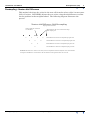
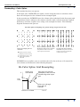
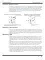
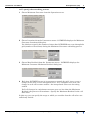
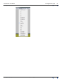
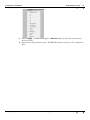
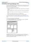
INTREPID User Manual
Library | Help | Top
Grid Operations (T25)
1
| Back |
Grid Operations (T25)
Top
The Grid Operations tool enables you to perform the following operations on gridded
datasets:
•
Resample a grid to change its cell size and/or origin. The user can choose between
four resampling methods.
•
Smooth a grid using the method of Minimum Curvature to improve its
appearance.
•
Rotate a grid about the grid origin.
•
Decimate a grid (by half) and create an output grid with double the cell size.
•
Extract single band grids from a multi-band grid.
•
Insert single band grids into a multi-band grid.
•
Detrend a grid using the 2D least squares technology from grid filter.
•
Convert the internal grid values from Integer/Real to Double Precision.
•
Export all non-null values from a grid to an INTREPID point dataset.
•
Create GRF grids for your selected input grid. You must supply date of survey
acquisition and survey flying height.
•
Capture the grid outline into a shape or polygon file.
•
Save the difference of a grid from the reference grid, without the requirement that
the grids have the same origin and cell size.
Tensor Grid Operations
Both standard Full tensor grids and the Falcon variant are supported in this tool
Library | Help | Top
•
Create a tensor grid from its component grids
•
Deconstruct a tensor grid into its component grids.
© 2012 Intrepid Geophysics
| Back |
INTREPID User Manual
Library | Help | Top
Grid Operations (T25)
2
| Back |
The Grid Operations tool
>> To use the Grid Operations tool
1
Choose Grid Operations from the Grid menu of the Project Manager, or use the
command gridop.exe. INTREPID will open the Grid Operations window.
2
If you have previously prepared file specifications and parameter settings for Grid
Operations, load the corresponding task specification file using Load Options from
the File menu. (See Specifying input and output files for detailed instructions.) If
all of the specifications are correct in this file, go to step 6. If you wish to modify
any settings, carry out the following steps as required.
3
Specify the input, reference and output datasets for the operation. Specify the
reference dataset for resampling or smoothing, if required. (See Specifying input
and output files for detailed instructions.)
4
If you are resampling, specify the cell size required for your resampled grid, and
select the resampling process you wish to use. (See Resampling a grid for details.)
5
If you are smoothing your grid, specify the number of iterations required and the
maximum residual difference for the minimum curvature smoothing process. (See
Smoothing a grid for details.)
6
Choose Apply. INTREPID will process the input grid and create an output grid.
7
If you wish to save the parameters for this process in a task specification (.job) file
in order to repeat a similar task later or for some other reason, use Save Options
from the File menu. (See Specifying input and output files for detailed
instructions.)
8
To exit from Grid Operations, choose Quit from the File menu.
___
You can view Help information by choosing options from the Help menu (See Help).
You can execute Grid Operations as a batch task using a task specification file (.job)
file that you have previously prepared. See Using task specification files for details.
Library | Help | Top
© 2012 Intrepid Geophysics
| Back |
INTREPID User Manual
Library | Help | Top
Grid Operations (T25)
3
| Back |
Specifying input and output files
For resampling, specify the original grid as the input grid. The origin of the new grid
can be set to that of an existing grid by selecting the existing grid as the reference
grid at the file selection stage. (See Preparing grids to avoid Grid Merge or Stitch tool
resampling for an example of a situation where you would wish to change the origin).
Specify a name for the output grid (the resampled grid).
For other operations, specify input and output grids.
Choose the corresponding options from the File menu to specify the datasets as
described above.
In each case INTREPID displays an Open dialog box. Use the directory and file
selector to locate the file you require. (See "Specifying input and output files" in
Introduction to INTREPID (R02) for information about specifying files).
Specify Input Grid Select the name of the grid dataset to be processed.
Specify Reference Grid The reference grid serves a distinctly different role
depending on whether you are resampling or smoothing your dataset.
If you are resampling a grid and wish to change the origin, use this to specify the
name of the existing grid you want to align with. (See Preparing grids to avoid
Grid Merge or Stitch tool resampling for an example of a situation where you
would wish to change the origin).
If you are smoothing a grid, use this to specify the name of the input dataset
which contains the original values for honouring by the minimum curvature
smoothing process.
If you do not specify a reference grid, INTREPID uses the input grid as the
reference grid.
Specify Output Grid Specify the name of the new grid dataset you are creating with
this grid operation.
Load Options Select a Grdop task specification file to preload the interactive session
with all the required file and parameter settings. (See Using task specification
files for information about task specification files).
Save Options Save the current Grid Operations file specifications and parameter
settings as a task specification file. (See Section Using task specification files for
more information).
Save Outline Poly Save the outline of the current Grid to a shape file of polygon
dataset.
Library | Help | Top
© 2012 Intrepid Geophysics
| Back |
INTREPID User Manual
Library | Help | Top
Grid Operations (T25)
4
| Back |
Resampling a grid
The Resampling option creates a new grid with a specified cell size and an origin
based on a specified reference grid. If you do not specify a reference grid, INTREPID
uses the origin of the input grid. It uses an interpolation process to calculate the
value for each output cell. The output cell size may be larger or smaller than the
input grid cell size. The output cell size does not need to be an exact multiple of the
input grid cell size.
Each cell value in the output grid is derived from a single input grid cell or a group of
neighbouring input grid cells. There are four resampling methods available to
interpolate values for the output cells. They are Newton 4th Order, Cubic Spline,
Minimum Curvature or Cubic Polynomial.
Newton 4th Order is our recommended general purpose method. It works well for a
wide range of datasets. It is the best method to use for radiometric or
electromagnetic data. It computes quickly on large grids, and honours the
original values faithfully.
Cubic Spline is best suited to datasets with small amplitude changes between cells
(ie; not radiometric or electromagnetic data). It is slower to compute than Newton
4th order.
Minimum Curvature is especially suited to potential field data. It is our
recommended method for magnetic or gravity datasets. It also computes quickly
on large grids, and honours original values well.
Cubic Polynomial is especially suited to potential field data. This method ensures
the highest quality local estimates of a field that is Laplacian. It provides
genuinely 2-dimensional interpolation, rather than one-dimensional interpolation
applied in orthogonal directions.
The default behavior of the Gridop tool is to resample the grid and then apply
Minimum Curvature smoothing to the output grid. The smoothing stage is optional
and can be turned off by setting the number of smoothing iterations to zero.
Library | Help | Top
© 2012 Intrepid Geophysics
| Back |
INTREPID User Manual
Library | Help | Top
Grid Operations (T25)
5
| Back |
>> To specify the resampling process
1
Specify input, reference and output grids (See Specifying input and output files
for detailed instructions).
2
Choose the method required from the Resampling menu (See below for process
descriptions).
3
Specify the grid cell size required for the resampling process. Choose Cellsize
from the Parameters menu.
INTREPID displays the Resampled Output Grid Cell Size dialog box.
You must specify the cell size before resampling the dataset. (The Cell Size text box
may not contain the cell size of the input dataset.) Specify the required cell size for
the output dataset (in the distance units of the dataset13) and choose OK.
1. If your dataset is geodetic (latitude and longitude) you need to specify the Grid Cell Size
in degrees.
Library | Help | Top
© 2012 Intrepid Geophysics
| Back |
INTREPID User Manual
Library | Help | Top
Grid Operations (T25)
6
| Back |
Resampling—Newton 4th Difference
This method calculates the value for the new cell from the values of the 5 nearest nonNull cell values. INTREPID adjusts the new value using the 4th difference to allow
for the gradient in that neighbourhood. The following diagram illustrates the
process.
Newton 4th Difference Grid Resampling
Input grid cell centroids
Output grid cell centroid to
be estimated
Δ1
Δ1
Δ2
Resampled so that rows and columns align
with output grid
Δ1
Δ1
Δ2
Δ2
Δ3
Δ3
Δ4
First differences between resampled input grid cells
Second differences between resampled input grid cells
Third differences between resampled input grid cells
Fourth difference between resampled input grid cells
INTREPID calculates the value for new cell by linear interpolation from the adjacent cells, then modifies
it using the 4th difference Δ4. This allows for the influence of the gradient near the new cell.
Library | Help | Top
© 2012 Intrepid Geophysics
| Back |
INTREPID User Manual
Library | Help | Top
Grid Operations (T25)
7
| Back |
Resampling—Cubic Spline
This method involves two passes.
In the first pass, INTREPID uses spline curves along the rows to calculate values
that will correspond to the columns in the resampled grid.
In the second pass, INTREPID uses the column values obtained in the first pass (and
original data values wherever the column coincides with a column from the original
dataset) to calculate a spline curve along each resampled column. The following
diagram illustrates the process.
Bi-cubic spline resampling of a grid to change origin and cell size.
First pass along rows: INTREPID
interpolates values in line with
output grid cell centroids.
Input and output grid cell
centroids
Input grid cell centroid
Second pass down columns:
INTREPID interpolates values for
output grid using interpolated
values from first pass.
Output grid cell centroid
Interpolated value in line
with output grid cell
centroids
INTREPID uses a spline curve to calculate the value for each new cell centroid in
each column as illustrated in the following diagram.
Bi-Cubic Spline Grid Resampling
Z
Output grid
cell centroid
Input grid cell centroids
resampled so that rows and
columns align with output
grid
Cell
value
Spline curve through
input grid cell
centroids
Grid row or column
Library | Help | Top
X or Y
© 2012 Intrepid Geophysics
| Back |
INTREPID User Manual
Library | Help | Top
Grid Operations (T25)
8
| Back |
Resampling—Minimum Curvature
INTREPID calculates the value of the new cell centroid using a weighted combination
of surrounding original cell values in one pass. The Minimum Curvature resampling
process uses values from the current original grid row, and from the two grid rows
either side of the current grid row. This method is an 'inverse' of the Honour Original
Data method (See "Minimum Curvature" in Old Gridding (T22)). The following
diagrams illustrate the process.
Minimum Curvature Grid Resampling
Input grid cell centroids
Minimum Curvature Grid Resampling
(ideal case of aligned cell centroids)
Input grid cell centroids
Output grid cell centroid to be estimated. INTREPID bases the
value on a weighted combination of surrounding input cell values,
honouring the exact location of the output cell.
Output grid cell centroid to
be estimated
Resampling—Cubic Polynomial
The Cubic Polynomial method is applicable to resampling within a grid cell, where
the values of the field at the corners and also the gradients, are known quantities. An
analytic function is used locally to calculate the field value at the required point. This
method is often used in contouring as well, to ensure high quality local estimates of a
field that is Laplacian.
Smoothing a grid
After resampling is completed, the resampled grid may appear pixelated or 'coarse
grained'. Intrepid will automatically apply Minimum Curvature smoothing to the
resampled grid. You can control the amount of smoothing by changing the number of
smoothing iterations, or turn it off completely by setting the number of iterations to
zero.
Smoothing can also be run as a separate operation on its own. You may have a grid
which for some reason or other appears pixelated. You can improve its appearance by
smoothing it. Specify your grid as the input grid. If you do not specify a reference
grid, INTREPID uses the cell values in the input dataset you have specified.
INTREPID uses a minimum curvature smoothing process. INTREPID will perform
several iterations through the grid, progressively examining and adjusting each cell
in the input grid according to the values of the cells in the corresponding region of the
reference grid. INTREPID will repeat the process until it has either completed the
number of specified iterations, or the maximum residual change for all interpolated
cells is less than the specified value.
Library | Help | Top
© 2012 Intrepid Geophysics
| Back |
INTREPID User Manual
Library | Help | Top
Grid Operations (T25)
9
| Back |
>> To specify the smoothing process
1
Choose Minimum Curvature from the Operation menu.
2
Choose Iterations from the Parameters menu. INTREPID displays the Minimum
Curvature Iterations dialog box.
Use this box to specify the number of times that INTREPID may scan through the
grid (number of iterations) during the Minimum Curvature smoothing process.
3
Choose Max Residual from the Parameters menu. INTREPID displays the
Minimum Curvature Maximum Residual dialog box.
4
Each time INTREPID scans in its attempt to smooth the grid, it may cause a
change in the value of each interpolated cell. As it completes each scan, the
change in each cell becomes smaller—the interpolated values are becoming
settled.
If all cell changes in a minimum curvature pass are less than the Maximum
Residual, the process will terminate. Specify the Maximum Residual in the cell
data units.
In this way you can specify the stage at which you consider that the cell values are
sufficiently settled.
Library | Help | Top
© 2012 Intrepid Geophysics
| Back |
INTREPID User Manual
Library | Help | Top
Grid Operations (T25)
10
| Back |
Rotating a grid
The Grid Operations tool can rotate a grid dataset. When a grid is rotated the result
is a change in the orientation of the grid rows and columns.
Grid rotation is performed around the grid origin. Positive angles are anti-clockwise.
You may declare the rotation angle parameter in either of two ways - either by
specifying the output grid rotation angle, or as a rotation through the specified
angle.
How to rotate a grid
>> To specify rotation for a grid dataset
1
Ensure that you have correctly specified an input and output dataset.
2
Choose Rotation from the Operation menu.
INTREPID displays the Grid Rotation dialog box which reports the current
rotation of the grid.
3
Specify the angle to or by which you wish to rotate the grid. Do this by either:
a) Selecting the target angle (Output Rotation Angle)
OR
b) the amount of rotation (Rotate Through Angle).
Then specify the angle in degrees (positive angles are anticlockwise) in the text
box corresponding to the selected option.
Library | Help | Top
4
Choose OK. INTREPID displays the Rotation Check dialog box which reports the
existing and proposed rotation settings for the grid.
5
Choose Yes if the settings correspond to your requirements.
6
Choose Apply in the main window.
© 2012 Intrepid Geophysics
| Back |
INTREPID User Manual
Library | Help | Top
Grid Operations (T25)
11
| Back |
Reasons for rotating a grid
When you are using INTREPID there are two situations where you may wish to
rotate a grid.
1
The INTREPID Bicubic Spline algorithm creates a rotated grid if the survey lines
were not acquired in a North–South or East–West direction. In this case you
would use the Gridop tool to unrotate the grid back to a rotation angle of zero.
2
If you want to use the INTREPID Decorrugation tool, this tool requires that the
input grid have rows and columns with North–South or East–West orientation.
However the INTREPID Minimum Curvature gridding algorithm creates grid
columns which run parallel to the survey lines. For survey lines which were not
acquired in a North–South or East–West direction, the grid rows and columns will
not have North–South or East–West orientation. In this case you will need to use
Gridop to rotate the grid such that the input grid for Decorrugation has the
correct orientation.
Extract grid from Multiband
This option enables you extract a new single band grid from an existing multiband
grid. To extract a single band grid:
1
Choose File > Specify Input Grid and select and open your existing multiband
grid.
2
From the Select Band dialog box select select the band name and choose OK.
3
Choose File > Specify Output, specify the single band grid file name and choose
OK.
4
Choose Operation > Extract grid from Multiband.
5
Choose Apply.
6
The Enter band number dialog box appears. Leave the entry as the default of 1/1.
Note: you cannot create a multiband grid using this prompt. Choose OK.
A message box appears Finished OK. Choose OK.
Implant grid into Multiband
This option enables you to combine existing single band grids into a new multiband
grid. To create a multiband grid in this way:
1
Choose File > Specify Input Grid and select your first single band grid.
2
Choose File > Specify Output and specify the multiband grid to be created.
3
Choose Operation > Implant grid into Multiband
4
Choose Apply.
5
In the Enter band number dialog box, enter the number of bands to be in your
multiband grid and the band number of the grid you specified in step 1.
For example, for a 3 band K-U-Th radiometric grid, if you have just specified band
1, enter 3/1 in the pop-up box.
Library | Help | Top
6
Choose OK and dismiss the message box that tells you the operation is complete.
7
Choose File > Specify Input Grid. Select your next single band grid.
8
Choose Apply. Enter the band number for this grid.
9
Repeat steps 7–8 until you have populated each band of your multiband grid.
© 2012 Intrepid Geophysics
| Back |
INTREPID User Manual
Library | Help | Top
Grid Operations (T25)
12
| Back |
Preparing grids to avoid Grid Merge or Stitch tool resampling
In some situations you may wish to combine a pair of grids with minimal Grid Stitch
tool resampling. Using Grid Operations you can specify an origin and cell size for the
resampled grid so it fits neatly with the grid to which you intend to stitch it. This will
reduce or eliminate the need for resampling during the Grid Stitch process.
Note. The more recent INTREPID GridMerge tool incorporates a much superior
resampling scheme to the earlier GridStitch, thus reducing the need to perform
resampling in Grid Operations.
>> To prepare grids for low resample stitching
If you wish to stitch grids A and B, and you will be resampling grid A to fit with grid
B:
1
Specify grid A as the input grid and grid B as the reference grid.
Specify a new grid cell size for the resampled dataset (A').
•
For minimal resampling of A' by Grid Stitch specify the cell size of A' as a
whole number multiple or fraction of the reference grid (B) cell size.
•
For no resampling of A' by Grid Stitch specify the cell size of A' equal to that of
B.
INTREPID produces a resampled dataset (A') whose origin is a whole number of
reference grid cells away from the origin of the reference grid (B).
2
Smooth grid A' if necessary.
___
You can then use Grid Stitch to stitch grids A' and B with minimal or no resampling.
Specify grid B as the grid to Calculate Geographic Reference From.
Specify the output cell size (Mesh Size) the same as that of grid B.
Grid Stitch will still perform adjustment and feathering as specified by you.
See Grid Stitch—combining two grids (T23) for full instructions on the use of the Grid
Stitch tool.
Create GRF grids
The Create GRF grids option creates three grids that cover the extents of the
currently selected input grid. The grids created are the amplitude, inclination and
declination of the Earth’s magnetic field. They are calculated using the IGRF
theoretical model. The calculation requires you to specify a survey flying height above
the spheroid (GPS height) and the survey acquisition date. This is done in the
Parameters > GRF parameters menu.
This feature can be useful for comparing trends in your supplied dataset with
predicted theory. You may also wish to restore a regional trend back into your
dataset. You can use the Spreadsheet editor tool to add this trend back into your
input grid.
Library | Help | Top
© 2012 Intrepid Geophysics
| Back |
INTREPID User Manual
Library | Help | Top
Grid Operations (T25)
13
| Back |
Dump Non-Null grid values to dataset
This operation uses the non-null values in your input grid to create a standard
INTREPID point dataset containing X,Y,Z fields. This is a “reverse” gridding process
that enables you to regain some of the original observations from a grid. This can be
useful for Geomodeller, as you sometimes need just a few points to indicate the
observation of a contact. See also the Dataset Sampler tool for similar functionality:
Dataset Sampler (T25a).
Note - when you Specify Output, you must include a database extension, eg: ..DIR,
otherwise the program will assume an output grid is required.
Detrend grid
This operation creates an output grid that is detrended using the same 2D polynomial
technology used in the Spectral domain grid filters tool (GridFFT). The required
degree of the detrending can be set in the Parameters > Detrend Polynomial Degree
menu option.
Constructing and deconstructing tensor grids
You can:
•
Construct a tensor grid from a number of component grids
•
Extract components of a tensor grid as independent grids.
Constructing a tensor grid
>> To construct a tensor grid from its components:
1
Library | Help | Top
Ensure that you have a set of six component grids:
•
With matching size, location and cell size
•
In ERMapper (.ers) or .semi format
2
Specify the output tensor grid. Choose File > Specify Output Grid.
3
Choose TensorGrids > Create from parts
4
Choose Apply. INTREPID displays Open dialog boxes for the component grids
XX, XY, ZX, YY, YZ, ZZ
5
Specify the component grids. INTREPID creates the tensor grid.
© 2012 Intrepid Geophysics
| Back |
INTREPID User Manual
Library | Help | Top
Library | Help | Top
Grid Operations (T25)
14
| Back |
© 2012 Intrepid Geophysics
| Back |
INTREPID User Manual
Library | Help | Top
Grid Operations (T25)
15
| Back |
Extracting components from a tensor grid
You can extract grids of the following components and derived values from a tensor
grid:
Component
Description
Auv,Ane,Buv,Bne,Guv,G
ne
Falcon components
XX, XY, ZX, YY, YZ, ZZ
Normal Component gradients
Max, Mid, Min eigenvalue
Principal components
Trace, SQRT 1st,
CubeRT 2nd
1st, 2nd, 3rd scaled invariants
Ratio I2 / I1
Ratio of second to first scaled invariant. This may
help to tell if causative body has 2-dimensional
characteristics. See:
Pedersen L.B., Rasmussen T.M., The Gradient
Tensor of Potential Field Anomalies: Some
Implications on Data Collection and Data
Processing of Maps. Geophysics, 55, No 12, 1558–
1566.
Phase
Independent rotational component of tensor
curvature. We use this for enhancing subtle
features and supressing strong features
Scalar Magnitude
David Clarke’s suggestion measure of invariant
amplitude
Curvature Gradient
Falcon Hilbert pair magnitude ( sqrt(Guv2 + Gne2))
WormsTotalHorizontal
Gradient
For scalar and tensor grids (sqrt(Tzx2 + Tyz2))
>> To extract a grid of a component or calculated value from a tensor grid:
1
Specify the input tensor grid. Choose File > Specify Input Grid.
Note: Always specify the input grid before selecting the operation that you want
to perform.
2
Library | Help | Top
Choose the component or derived values that you want to estract. Choose the
required option from the TensorGrid menu
© 2012 Intrepid Geophysics
| Back |
INTREPID User Manual
Library | Help | Top
Library | Help | Top
Grid Operations (T25)
16
| Back |
3
Choose Apply. INTREPID displays a Save As dialog box for the component or
derived values
4
Specify the output dataset name. INTREPID extracts and saves the component
grid.
© 2012 Intrepid Geophysics
| Back |
INTREPID User Manual
Library | Help | Top
Grid Operations (T25)
17
| Back |
Optimising processing performance for large grids
For large grids, INTREPID uses a tiling system. This involves processing the grid a
section at a time. You can optimise the performance of your computer by adjusting
the value of the INTREPID_MEMORY system parameter.
Apart from this optimising adjustment, the tiling process and the decision to use it is
automatic. See "INTREPID Memory limits and tiling" in Configuring and using
INTREPID (R04)for information about INTREPID_MEMORY.
Apply
When you choose Apply, INTREPID performs the resampling or smoothing grid
operation as specified by you, saving the grid
•
When finished for a small grid or
•
As it proceeds for a large grid where it is using the tiling process (See Optimising
processing performance for large grids for details about small and large grids and
tiling).
Exit from Grid Operations
To exit from Grid Operations choose Quit from the File menu.
Help
You can use the help menu to display help text on the topics shown in the menu
illustration below.
Library | Help | Top
© 2012 Intrepid Geophysics
| Back |
INTREPID User Manual
Library | Help | Top
Grid Operations (T25)
18
| Back |
Using task specification files
You can store sets of file specifications and parameter settings for Grid Operations in
task specification (.job) files. As at V5.0 Intrepid, all of this functionailty is moved
to the GOOGLE protobuf syntax and the complete datamodel is published in the API
section. This gives the advantage of less code for Intrepid to maintaing, and better
parsers and a new way to do interprocess communication across disparate servers,
operating systems etc.
>> To create a task specification file with the Grid Operations tool
1
Specify all files and parameters.
2
If possible, execute the task (choose Apply) to ensure that it will work.
3
Choose Save Options from the File menu. Specify a task specification file
(INTREPID will add the extension .job) INTREPID will create the file with the
settings current at the time of the Save Options operation.
For full instructions on creating and editing task specification files see INTREPID
task specification (.job) files (R06) files.
>> To use a task specification file in an interactive Grid Operations session
Load the task specification (.job) file (File menu, Load Options), modify any settings
as required, then choose Apply.
>> To use a task specification file for a batch mode Grid Operations task
1
Type the command gridop.exe with the switch -batch followed by the name
(and path if necessary) of the task specification file.
For example, if you had a task specification file called surv_conv.job in the current
directory you would use the commands
gridop.exe –batch surv_conv.job
Library | Help | Top
© 2012 Intrepid Geophysics
| Back |
INTREPID User Manual
Library | Help | Top
Grid Operations (T25)
19
| Back |
Task specification file examples
Here is an example of an Grid Operations resampling task specification file.
Process Begin
Name = gridop
Input = /disk1/data/mlevel_grid
Reference = /disk1/data/mlnext_grid
Output = /disk1/data/mlevres_grid
Parameters Begin
Method = Newton_4th_Order
Cellsize = 50.0
Parameters End
Process End
Here is an example of an Grid Operations smoothing task specification file.
Process Begin
Name = gridop
Input = /disk1/data/mlevres_grid
Reference = /disk1/data/mlevel_grid
Output = /disk1/data/mlevsm_grid
Parameters Begin
Method = Smoothing
MaxResidual = 0.04
Iterations = 80
Parameters End
Process End
Here is an example of an Grid Operations smoothing task specification file which
shows the syntax for most of the current options.
Process Begin
Name = gridop
Input = /disk1/data/mlevres_grid
Output = /disk1/data/grdop_grid
Parameters Begin
# Method options are as follows:
# Cubic_Spline Newton_4th_Order Minimum_curvature Cubic Smoothing
# Rotate SubSample GetBand PutBand
Method = Minimum_curvature
Cellsize = 15.
MaxResidual = 0.5
Iterations = 100
OutputPrecision = IEEE4ByteReal
OutputRotation = 0.0
# only used for getband method
GetBand Begin
Band = 1
GetBand End
# only used for putband method
PutBand Begin
Band = 1
NBands = 1
PutBand End
Library | Help | Top
© 2012 Intrepid Geophysics
| Back |
INTREPID User Manual
Library | Help | Top
Grid Operations (T25)
20
| Back |
# only used for subsample method
SubSample Begin
SS = 0
SL = 0
NL = 100
NS = 100
SINC = 2 # sub sample increment
LINC = 2 # line increment
SubSample End
Parameters End
Process End
Library | Help | Top
© 2012 Intrepid Geophysics
| Back |