1
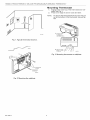
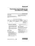
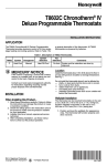
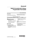
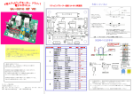
Honeywell
T8665A Chronotherm®IV
Deluxe Programmable
Wireless Thermostat
APPLICATION
The T8665 Chronotherm® IV Wireless Thermostat
provides electronic control of 24 Vac heating end cooling
systems. It must be used with a W8665 Receiver
Module. Refer to Table 1 for a general description of the
thermostat. The T8665A Thermostats are batterypowered.
Table I. T8665A Thermostat Description.
T8665
A
System
Changeover
Heat-Cool
Automatic
System Selection
Heat-Off-Cool-Auto
Fan Selection
On-Auto
Comments
System and fan
selections are entered at
keyboard.
Location
MERCURYNOTICE
tf this control is replacing a control that contains
mercury in a sealed tube, do not place your old
control in the trash.
Contact your local waste management authority
for instructions regarding recycling and the
proper disposal of the old thermostat.
INSTALLATION
Accessory
Required
(Not Included)
Select one of the receiver modules for your application:
-W8665A Receiver Module (RM) for single zone
applications.
-W8665E RF Zone
Panel for up to three zones.
Install the thermostat about 5 ff (1.5m) above the floor in
an area with good air circulation at average temperature.
See Fig. 1.
Do not install the thermostat where it can be affected by:
-- drafts, or dead spots behind doors and in corners.
-- hot or cold air from ducts.
-- radiant heat from sun or appliances.
-- concealed pipes and chimneys.
-- unheated (uncooled) areas such as an outside wall
behind the thermostat.
Wallplate
1.
TM
2.
When Installing
1.
2.
3.
4.
this Product...
Read these instructions carefully. Failure to follow
the instructions can damage the product or cause
a hazardous condition.
Check the ratings given in the instructions and on
the product to make sure the product is suitable for
your application.
Installer must be a trained, experienced service
technician.
After completing installation, use these instructions
to check out the product operation.
® US. Registered
Installation
The thermostat can be mounted horizontally on the wall.
3.
4.
5.
6.
7.
Position and level the wallplate (for appearance
only). The thermostat functions correctly even
when not level.
Use e pencil to mark the mounting holes. See Fig.
2.
Remove the wallplate from the wall and drill two
3/16 in. holes in the wall (if drywall) as marked. For
firmer material such as plaster, drill two 7/32 in.
holes.
Gently tap anchors (provided) into the drilled holes
until flush with the wall.
Position the wallptate over the holes.
Loosely insert the mounting screws into the holes.
Tighten the mounting screws.
Trademark
Copyright ® 2002 Honeywell
•
_
• All Rights Reserved
69-1535-3
T8665A
CHRONOTHERM®
IV DELUXE
PROGRAMMABLE
WIRELESS
THERMOSTAT
Mounting
1.
2.
NOTE:
Fig. 1. Typical thermostat
Thermostat
Engage tabs at the top of the thermostat and wallplate. See Fig. 3.
Press lower edge of case to close and latch.
To remove the thermostat from the wall, first pull
out at the bottom of the thermostat; remove top
last.
location.
Fig. 3. Mounting thermostat
Fig.
69-1535-3
2. Mounting
the waltplate.
2
on wallplate.
T8665A
Using Thermostat
CHRONOTHERM®
IV DELUXE
Keys
PROGRAMMABLE
WIRELESS
THERMOSTAT
• configure Installer Setup,
• check self-test,
• set the system operation,
• set the fan operation.
See Pig. 4 for key locations.
The thermostat keys are used to:
• set current day end time.
• program times and setpoints for heating and cooling.
• temporarily override program temperatures
• display present setting,
Fig. 4. T8665A key locations and descriptions.
Setting up T8665A to Send Signal
to W8665A, E Receiver Module
Multizone Applications
one W8665E)
The T8665A Thermostat must be set up to send signals
to the W8665 Receiver Module. Use the W8665A
Receiver for single-zone applications. Use the W8665E
RF Zone TM Panel for up to three T8665A Thermostats for
multizone applications.
IMPORTANT
The thermostats must be set up one zone at a
time to ensure a unique address is used for
each zone.
1.
Single Zone
Applications
(one T8665N
one W8665A)
1. Place the Zone 1 DiP switch on the W8665A
Receiver to the On position.
NOTE:
2.
3.
Observe that the Zone 1 LED on the W8665
flashes.
Press the thermostat Fan key to the On position.
The Receiver accepts the message, stores the
identity of that zone, end stops flashing the Zone 1
LED. The thermostat is now set up to send signals
to Zone 1 of the W8665E Receiver.
Observe that the Zone 1 LED on the W8665
flashes.
NOTE:
The word On end a fan blade _ appear in the
thermostat display to indicate the thermostat is
calling for the fan to turn on.
3.
At any time, if you want to stop the thermostat
from sending signals to the W8665 Receiver,
simply turn the DIP switch to the Off position.
Follow the instructions in steps above to set up
the thermostat again to send signals to the
W8665A Receiver.
4.
3
The word On and a fan blade tt appear in the
thermostat display to indicate the thermostat is
calling for the fan to turn on.
Set the System and Fan keys to the desired locations.
NOTE:
Set the System and Fan keys to the desired locations.
NOTE:
Place the Zone 1 DIP switch on the W8665E
Receiver to the On position.
NOTE:
Press the thermostat Fan key to the On position.
The receiver accepts the message, stores identity
end then stops flashing the Zone 1 LED. The thermostat is now set up to send signals the W8665A
Receiver.
NOTE:
(Up to three T8665A!
At any time, if you want to stop the thermostat
from sending signals to the W8665 Receiver,
simply turn the DIP switch to the Off position.
Follow the instructions in steps above to set up
the thermostat again to send signals to the
W8665E Receiver.
Repeat steps 1-3 for zones two and three.
69-1535-3
T8665A
5.
CHRONOTHERM®
IV DELUXE
PROGRAMMABLE
WIRELESS
THERMOSTAT
Attach the zone number stickers, included with the
thermostat, onto the thermostat case on the inside
of the thermostat cover. See Fig. 5.
P_aceone_e4_nside
e_cht_efmostat_oof
MI3426
Fig. 5. Zone stickers included
Thermostat.
with T8665A
SETTINGS
Fig. 6. Thermostat
NOTE:
System and Fan Settings
The system default setting is Heat and the fan default
setting is Auto. Use the System and Fan keys to change
the settings. See Fig. 6. The fan settings can be set for
each program period individually. The system selection is
for all the program periods.
System
and
Fan
key locations.
Always press the keys with your fingertip or similar blunt tool. Sharp instruments like a pen or
pencil point can damage the keyboard.
Programmed TemperatureSettings
Refer to Table 2 for the default program. If the daytime
energy savings period is not used, press the period key
(Leave or Return) until the time is blank. The fan setting
feature is available on select thermostat models. See
Owner's Guide for complete instructions on changing the
program.
System settings control the thermostat operation as
follows:
Heat: The thermostat controls the heating.
Off: Both the heating and cooling are off.
Cool: The thermostat controls the cooling.
Table 2. Default Program Settings.
Auto: The thermostat automatically changes between
heating and cooling operation, depending on the
indoor temperature.
Period
Cool
Setpoint
Fan
Setting
6:00
AM
70°F
(21°C)
78°F
(25.5°C)
Auto
Leave
8:00
AM
62°F
(16.5°C)
85°F
(29.5°C)
Auto
Return
6:00
PM
7O°F
(21°C)
78°F
(25.5°C)
Auto
Sleep
10:00
PM
62°F
(16.5°C)
82°F
(28°C)
Auto
Auto: Fan operates with equipment.
4
Heat
Setpoint
Wake
Fan settings control the system fan as follows:
On: Fan operates continuously.
69-1535-3
Time
T8665A
CHRONOTHERM®
IV DELUXE
PROGRAMMABLE
WIRELESS
THERMOSTAT
INSTALLER SETUP
NOTE:
For most applications, the thermostat factorysettings do not need to be changed. Review the
factory default settings in Table 3 and, if no
changes are necessary, go to the Installer SelfTest section.
Iml
The Installer Setup is used to customize the thermostat
to specific systems. Some of the options include
temperature display and system changeover. Installer
Setup numbers are listed in Table 3. The table includes
all the configuration options and the factory-settings for
the T8665.
/
/'
NUMBER D_SPLAY
(COLUMN 2 OF TABLE 3)
CHOICE DISPLAY (COLUMN 3
OR 5 OF TABLE 3)
MI4GI8
A combination of key presses are required to use the
Installer Setup feature:
-- To enter the Installer Setup, press and hold the
Information i key with the increase • and decrease •
keys until the first number is displayed. All display
segments appear for approximately three seconds
before the number is displayed. See Fig. 7 and 8.
-- To advance to the next Installer Setup, press the Time
•
key.
-- To change a setting, use the increase • or decrease
•
key.
-- To scroll the Installer Setup numbers backward, press
the Time • key.
-- To exit the Installer Setup, press Run Program.
Fig.
1
8. Display
of Installer
Setup
number
and settings.
CAUTION
Equipment Damage Hazard.
Electric heat and heat pump systems must
run with fan.
Configure to 1 in Installer Setup number 2 to
prevent equipment damage.
IMPORTANT
Only configured numbers are shown on the
device.For example: If thermostat does not
have a system key: Installer Setup Number f2
will not display Review Table 3 factory settings
and mark any desired changes in the Actual
Settings column. When Installer Setup is complete, review the settings to confirm they Matthew system.
Fig.
7. Display
of all LCD
segments.
5
69-1535-3
T8665A
CHRONOTHERM®
IV DELUXE
Table
Select
Factory
1
Fan operation a
2
Installer
Setup
THERMOSTAT
Options.
Setting
(Press
•
or
Choices
•
key to change)
•
Actual
change)
Not used
3. Thermostat
WIRELESS
Other
Installer
Setup
Number
(Press
Time
key to
PROGRAMMABLE
Display
Description
Display
Conventional
applications where
equipment controls
fan operation in heat
mode
Description
Heat pump or electric heat
applications where
thermostat controls fan
3peration in heat mode
Not used
Heating cycle
rate
6--6 cph used for
conventional heat
1,3or9
1--1 cph used for radiant
floor heat, gravity system
3--3 cph used for hot
water systems or high
sfficiency furnaces
9--9 cph used for electric
heat systems
Not used
5 thru 11
System setting
adjustment
12
1
Manual changeover
0 or 2
3--Auto changeover
2--Auto only
Adaptive
Intelligent
Recovery
control
13
0
Adaptive Intelligent
Recovery
control
is activated (system
starts early so
setpoint is reached
by start of program
period)
1
Conventional recovery
(system starts recovery at
programmed time)
Temperature is
displayed in °F
1
Temperature is displayed
in °C
TM
TM
Degree
temperature
display
Not used
14
15
m
Clock format
16
0
12-hour clock format 1
24-hour clock format
Not used
17 and 18
Extended fan
operation in
heating a
19
0
No extended fan
operation after the
call for heat ends
1
Fan operation is extended
90 seconds after the call
for
heat ends.
Extended fan
operation in
cooling a
2O
No extended fan
operation after the
call for cool ends
1
Fan operation is extended
90 seconds after the call
for
coot ends.
Not used
21 thru
Deadband
30
29
Heating and cooling 4 thru 10
setpoints can be set
no closer than 3°F
(1.5°C)
Heating and cooling
setpoints can be set no
closer than the chosen
Value:
4--4°F
5--5°F
B--6°F
7--7°F
(2°C)
(215°C)
(3°C)
(3.5°C)
8--8°F(4°C)
9--9°F (4.5°C)
10--10°F (5°C)
Not used
31 and 32
Minimum off
time for the
compressor
33
69-1535-3
five-minute
0 thru 4
minimum off time for
the compressor
6
Minimum number of
minutes (0 thru 5) the
compressor will be off
between calls for the
compressor
Setting
T8665A
CHRONOTHERM®
Table 3. Thermostat
IV DELUXE
PROGRAMMABLE
Installer Setup Options.
WIRELESS
THERMOSTAT
(Continued)
Temperature
range stops in
heating
34
90
Highest setpoint
heating can be set
to
40 to 89
Temperature range (I°F
increments) heating
setpoint can be set to
Temperature
range stops in
cooling
35
45
Lowest setpoint
46 to 99
cooling can be set to
Temperature range (I°F
increments) cooling
setpoint can be set to
Not used
36
....
Temperature
display
adjustment
37
0
No difference in
displayed
temperature and
actual room
temperature
3 thru
-3
1--Display adjusts to I°F
higher than actual room
temperature
2--Display adjusts to 2°F
higher than actual room
temperature
3--Display adjusts to 3°F
higher than actual room
temperature
-1--Display adjusts to I°F
lower than actual room
temperature
-2--Display adjusts to 2°F
lower than actual room
temperature
-3--Display adjusts to 3°F
lower than actual room
temperature
Furnace air
filter timer
(pushbutton
System keys)
43
2
30 days
(System run time)
0, 1, 3,4
3--Off
1--10 days
3--60 days
4--120 days
Time is counted when
heat, cool or fan is
running.)
Humidifier pad 44
monitor
0
Off
1, 2, 3
1--90 days
2--180 days
3--365 days
Time is counted by
calendar days in heat
mode.)
Ultraviolet air
45
treatment (UV)
system lamp
monitor
0
Off
1
1--365 days
Time is counted by
calendar days in any
mode.)
Number 2 must be set to 1 to extend fan operation.
IMPORTANT
Review the settings to confirm they match the
system. Press Run Program to exit the Installer
Setup. The thermostat has saved the linstaller
Setup changes and initiated a reset to operate
using the new settings. Be sure to set the current day and time immediately.
7
69-1535-3
T8665A
CHRONOTHERM®
IV DELUXE
PROGRAMMABLE
WIRELESS
THERMOSTAT
Setting Current Day and Time
1.
Press Set Current Day/Time.
NOTE:
On initial powerup or after an extended power
loss, 1:00 pm flashes on the display until a key
is pressed.
"Oaylight
}
)
Cf'
,_
M14622
4.
_Set Current_=
I Day/Time ]
I=
_
Time
Press Ran Program.
f'U ____
M.,
MI4GI9
2.
Press Day until the current day is displayed.
NOTE:
Sun=Sunday, Mon=Monday,
Tue=Tuesday, Wed=Wednesday,
Thu=Thursday, Fri=Friday, Sat=Saturday.
Viewing or Resetting Timer Settings
When the thermostat activates a timer, the thermostat
flashes Filter until the timer resets.
1.
'
Rest the timer by pressing the i key until the
expired time is displayed.
I
i,i-u-r
M1462O
3.
Press Time • or Time •
displayed.
NOTE:
until the current time is
Filtel
LI !!
Days
m
II--
CJ
Tapping Set Current Day/Time changes the time
in one-hour increments.
M20_3
Press the Time •
key to reset the timer.
Ti_e
_-iLl
j
J.o
Filtel
M14621
NOTE:
_!
0
I!-M2o_4
If the current time is Daylight Savings Time,
press Daylight Time until DST is displayed.
3.
NOTE:
69-1535-3
Days
8
Press the Ran Program key.
You can view the number of days remaining at
any time by pressing the i key three or four
times. If more than one timer is active, all active
timers show sequentially when pressing the i
key several times.
T8665A
CHRONOTHERM®
IV DELUXE
PROGRAMMABLE
WIRELESS
THERMOSTAT
INSTALLER SYSTEM TEST
Use the Installer System Test to check the thermostat
operation. Refer to Table 4 for a list of the available
installer System Tests.
Wait_
CAUTION
_
Tempc_ary
Setting
w
....
w
w
! at j!,!
*'
.. system
Em Heat
*Auo
Filterr_lt_
Days _
_11_
D: .Fan----]
MonTueWedThuFri
SatSun ReplBattRoomOutdoor_°_
On
Wake Leave Return Sleep DST THeat CoolA i
Auto]
Equipment Damage Hazard.
Compressor damage can result if compressor
is cycled too quickly.
Be aware that compressor minimum off time is
bypassed during the installer System Test.
M4559
Fig.
9. LCD
segments
display.
To start the system test:
1.
2.
Press and hold increase • and decrease •
at
the same time until 10 appears.
Observe atl segments of the display are displayed
before the 10 appears. See Fig. 9 and 10.
irl
Table 4. Tests Available in Installer
Test Number
I
I
System Test.
System Test Description
Fig. 10. Test number display.
10-19
Heating equipment can be turned
on and off.
30-39
Refer to Table 5 for the instructions and description of the
specific tests.
Cooling equipment can be turned
on and off.
40-49
Pan equipment can be turned on
and off.
60 0 to
60 19
Keyboard keys test.
70-79
Thermostat information, including
date code and soak!are versions,
are displayed.
Table 5. Installer
NOTE:
Press Time • to advance to the next test and
press Time •
to go back to the previous test.
Press Run Program to exit the system test.
System Test Options.
Key to Press I Test Number
I
Heating Equipment System Test
Description
Time
10
Enter heating equipment system test.
•
11
Heat comes on. When Installer Setup number 2 is 1, the system fan is also
energized.
•
Cooling
12
Equipment
Heat and system fan turn off.
System Test
Time
30
Change from heating to cooling equipment system test.
•
31
Cool and system fan come on.
•
30
Cool and system fan turn off.
Fan Equipment
Time
•
•
Key Operation
Time
NOTE:
System Test
40
41
Change from cooling to fan equipment system test.
Fan comes on.
40
Fan turns off.
System Teat
160 2
IChange from fan to key operation system test.
Press any key and the displayed number will change. Press Time • to go to the previous test and Time •
to go to the next test. The Run Program key will not exit this test. Press Time • or Time •
and then the Run
Program key to exit.
9
69-1535-3
T8665A
CHRONOTHERM@
IV DELUXE
PROGRAMMABLE
WIRELESS
THERMOSTAT
Thermostat Information
1.
Press the Time key to access the them_ostat information.
LIB
rl
=l J=l
I LI
M14615
4.
5.
M1461S
2.
Press the increase •
key to display the production date code. The first two large digits are the
month and the third digit is the last digit of the year
(example: 027=February 1997).
]I
u
e
M14817
Press the increase key • again to display the software identification code. (Example: 02 = software
ID code 2).
69-1535-3
Press the increase key •
again to display the
software revision number (example:001
= revision
number 1).
Press the increase • key again te display the
EEPROM identification cede (example: 314 =
EEPROM ID 314).
Press the Run Program key to exit the system test.
The system test times out after four minutes without any key presses.
M14614
3.
1
10
T8665A CHRONOTHERM®
IV DELUXE PROGRAMMABLE
WIRELESS THERMOSTAT
TROUBLESHOOTING GUIDE
For troubleshooting,
see Table 6.
Table 6. Troubleshooting
Symptom
Guide.
Possible Cause
Action
Display does not Thermostat is not being
come on.
_owered.
Check if batteries are present and installed correctly.
-If batteries are present and installed correctly, replace thermostat.
Temperature
display is
Room temperature display
has been reconfigured.
Enter Installer Setup number 37 and reconfigure the display.
incorrect.
Thermostat is configured
for °F or °C display.
Enter Installer Setup number 14 and reconfigure the display.
Poor choice of thermostat
location.
Relocate the thermostat.
The upper or lower
temperature limits were
reached.
The setpoint temperature
range stops were
configured.
Check the temperature setpoints:
° Heating limits are 40 to 90°F (4.5 to 32°C)
° Cooling limits are 48 to 99°F (7 to 35°C)
Check Installer Setup numbers 34 and 35 and reconfigure the setpoint
stops.
Temperature
settings do not
change,
(Example:
Cannot set the
heating higher or
the cooling
lower.)
Heating does not Thermostat is calling for
come on.
heat (flame icon is in
display).
•
•
Thermostat is not calling
•
for heat (no flame icon is in •
display).
Thermostat minimum off
time is activated.
Troubleshoot the W8665 Receiver Module.
Troubleshoot the heating equipment.
Raise heating setpoint above room temperature.
Check if the W8665 is set up to receive signals from this thermostat.
-Set up W8665 to receive signals.
Wait up to five minutes for the system to respond.
System selection is not set Set system selection to Heat.
to Heat.
Heating setpoint is below
room temperature.
Cooling does not Thermostat minimum off
come on.
time is activated.
Check heating setpoint. Set heating setpoint to desired temperature.
•
•
Wait up to five minutes for the system to respond.
Enter Installer Setup number 33. Reconfigure minimum off time
(if required).
System selection is not set Set system selection to Cool.
to Cook
Cool setpoint is above
room temperature.
Check cooling setpoint. Set cooling setpoint to desired temperature.
Thermostat is calling for
cool (snowflake is in
display).
•
•
Thermostat is not calling
•
for cool (no snowflake icon
is in display).
System on
indicator
Troubleshoot cooling equipment.
Troubleshoot W8665 Receiver Module.
Check if the W8665 is set up to receive signals from the thermostat.
-Set up W8665 to receive signals.
( (_ = heat,
Fan operation set for 0
conventional heat) when it
should be set for 1 (electric
heat).
Enter Installer Setup number 2 and reconfigure the fan operation.
>_4 = cool) is
displayed, butno
warm or cool air
is coming from
Conventional heating
Wait a minute after seeing the on indicator and then check the
equipment tums on the fan registers.
when the furnace has
warmed up to a setpoint.
the registers.
Heating or cooling
equipment is not operating.
Verify operation of heating or cooling equipment in self-test.
Thermostat
backlight
appears dim.
Backtight may fade over
the life of the batteries,
•
•
Wait unit Replace Battery indicator is illuminated and replace
batteries.
Replace batteries now.
11
69-1535-3
T8555A
CHRONOTHERM®
IV DELUXE
PROGRAMMABLE
WIRELESS
THERMOSTAT
FCCID: CFS8DL5800STAT
CANADA: 1748A12111
This device complies with Part 15 of the FCC Rules. Operation is subject to the following two conditions:
(1) This device may not cause harmful interference, and
(2) This device must accept any interference received, including interference that may cause undesired operation.
FEDERALCOMMUNICATIONSCOMMISSION(FCC) STATEMENT
This equipment has been tested to FCC requirements and has been found acceptable for use. The FCC requires the
following statement for your information:
This equipment generates and uses radio frequency energy and, if not installed and used properly; that is, in strict
accordance wih the manufacturer's instructions, may cause interference to radio and television reception. It has been
type tested and found to comply with the limits for a Class B computing device in accordance with the specifications in
Part 15 of FCC Rules, which are designed to provide reasonable protection against such interference in a residential
installation. However, there is no guarantee that interference will not occur in a particular installation. If this equipment
does cause interference to radio or television reception, which can be determined by turning the equipment off and on,
the user is encouraged to try to correct the interference by one or more of the following measures:
•
•
•
•
•
If using an indoor antenna, have a quality outdoor antenna installed.
Reorient the receiving antenna until interference is reduced or eliminated.
Move the radio or television receiver away from the receiver/control.
Move the antenna leads away from any wire runs to the receiver/controL
Plug the receiver/control into a different outlet so that it and the radio or television receiver are on different branch
circuits.
if necessary, the user should consult the dealer or an experienced radio/television technician for additional
suggestions. The user or installer may find the following booklet prepared by the Federal Communications Commission
helpful:
"Interference Handbook"
This booklet is available under Stock No. 004-000-00450-7
20402.
from the US Government Printing Office, Washington, DC
The user shall not make any changes or modifications to the equipment unless authorized by the Installation
Instructions or User's Manual Unauthorized changes or modifications could void the user's authority to operate the
equipmenL
Honeywell
Autonmtion
Hon=_
1985 Douglas
Oolden
and
Control
Solutions
ell
Valley,
69-1535-3
Hone}_
Dave
MN
GH
ell Limlted-Honeywell
Norfll
35 D_ami¢
55422
Sca_oi_ugh,
M IV 4Z9
Rev. 11-02
Printed
Limltde
Dave
Ontario
in U.S_.
wwwhoneywe]Lcom/yourhome