1
Honeywell
W8665A,E
RF Receiver Module
APPLICATION
The W8665A,E RF Receiver Module (RM) provides 24
Vac control of HVAC equipment when used with a
T8665A Chronotherm® IV Wireless Programmable
Thermostat. The W8665A can be used with 1H/1C
Table
Model
Application
1. W8665
single-zone conventional applications. The W8665E can
be used with up to three zones when used with a
Honeywell EMM-3 Electronic MiniZone TM Panel,
EMM-3U Universal Electronic MiniZone
Panel,
TZ-3 TotalZone® Control Panel or TZ-4 TotalZone® Zone
Control Panel. See Table 1.
TM
Description.
Zones
Stages
Comments
W8665A
Conventional gas, oil or
electric systems.
1H/1C
One
Use with T8665A Wireless
Thermostat.
W8665E
Conventional gas, oil or
electric systems.
1H/1C
Up to three
Use with T8665A Wireless
Thermostats.
Use with EMM-3 Electronic
MiniZone TM Panel
Single or multi-stage
conventional or heat
pump systems.
Up to 2H/2C
Use with T8665A Wireless
Thermostats.
Use with EMM-3U Universal
Electronic MiniZone
Panel.
1H/1C orupto
3H/2C
Use with T8665A Wireless
Thermostats.
Use with TZ-3 TotalZone
Zone
Control Panel a or TZ-4
TotalZone® Zone Control Panel b.
TM
TM
aTZ-3 can work with up to 30 zones. Must use multiple W8665E Receiver Modules.
bTZ-4 can work with up to 32 zones. Must use multiple W8665E Receiver Modules.
INSTALLATION
1.
CAUTION
2.
Equipment Damage Hazard.
Do not mount W8665 inside HVAC equipment.
Do not mount on metal surfaces.
Mount only on wall.
¢_)U.S. Registered
Copyright
Trademark
¢) 2003 Honeywe41 •
3.
4.
Mount the thermostats in each zone of the living
space using the installation instructions provided
with each thermostat.
Mount the dampers in the ductwork using the
installation instructions provided with each damper.
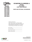
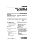
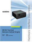
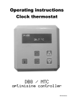
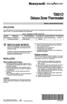
Mount the W8665 RF Receiver Module near the
HVAC equipment on a walt. See Fig. 1.
Level the W8665 for appearance only.
/_
_
• All Rights Reserved
69-1d30-1
W8665A,E
RF RECEIVER
MODULE
Wiring the W8665E
Connect the RF Receiver Module zones to the
appropriate thermostat zone connections on the EMM-3
Electronic MiniZone
Panel, EMM-3U Universal
Electronic MiniZone
Panel, TZ-3 TotaiZone TMZone
Control Panel or TZ-4 TotalZone® Zone Control Panel.
See Fig. 7 through 16 and Table 3.
TM
TM
W8665
Table 3. W8665E Terminal
Designations.
M20162
Terminal
Designation
Fig. 1. W8665 mounting location
24 Vac transformer hot.
Powers RF receiver module.
C
24 Vac transformer common.
Powers RF receiver module.
RZ
24 Vac system transformer.
The three RZ terminals are
internally connected.
Connect RZ to Zone 1 R terminal
on zone panel, as desired. (Not
required.)
RZ
24 Vac system transformer.
The three RZ terminals are
internally connected.
Connect RZ to Zone 2 R terminal
on zone panel, as desired. (Not
required.)
RZ
24 Vac system transformer.
The three RZ terminals are
internally connected.
Connect RZ to Zone 3 R terminal
on zone panel, as desired. (Not
required.)
Zone 1 Y
Stage 1 cool.
Zone 1 W
Stage 1 heat.
Zone 1 G
Fan
Zone 2 Y
Stage 1 cool.
Zone 2 W
Stage 1 heat.
Zone 2 G
Fan
Zone 3 Y
Stage 1 cool.
Zone 3 W
Stage 1 heat.
Zone 3 G
Fan
WIRING
All wiring must comply with local electric codes and
ordinances. See Fig. 2 through 16 wiring diagrams for
specific applications. Refer to Tables 2 and 3 for terminal
designations.
CAUTION
Voltage Hazard.
Can cause electrical shock or equipment
damage.
Disconnect power before beginning installation.
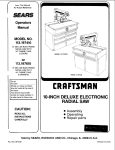
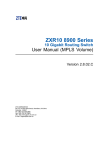
Wiring the W8665A
Connect the RF Receiver Module to the equipment
loads. See Fig. 2 through 6 and Table 2.
Table 2. W8665A Terminal Designations.
Terminal
Designation
R
Function
24 Vac transformer hot.
Powers RF receiver module.
C
24 Vac transformer common.
Powers RF receiver module.
RZ
24 Vac system transformer.
Factory installed jumper between
R and RZ terminals. Use RZ as a
convenience terminal, as
desired.
Y
Stage 1 cool.
W
Stage 1 heat.
G
Fan
69-1630-1
Function
R
2
W8665A,E
__J
COMM
RF RECEIVER
MODULE
ZON5
O
O
LED
LED
W8665A
L
LED STATES:
COMM_
RAPIDLY FLASHING GREEN RECEIVING INFORMATION FROMTHERMOSTAT
GREEN OFF STANgBY_ READY TO RECEIVE INFORMATION
ZONE¸
RSDON SYSTEM (HEAT COOL OR FAN) ISON
RED OFF SYSTEM (HEAT COOL OR FAN) ISOFF
FLASHJNGRED ERROR NOTRECEIVINGSlGNALFROMTHERMOSTAT
RAPIDLY FLASHING RED RECEIVER IN SET UP MODE
DIP SWITCH SETT_NaS:
OFF_NOT SET UP TO RECEI\'E INFORMATION FROM A THERMOSTAT
ON_READY TO RECEIVE INFORMATION FROMTHERMOSTAT AFTER
SET UP IS COMPLETE
ZONE I
ZONE 2
ZONE S
SET-UP:
MOVE 91P SWITCH TO O_ POSITION AND MAKE THERMOSTAT CALL FOR FAN
NOTE¸ ALL OTHER THERMOSTATS MUST BE OFF (NOT CALLING) DURING SET UP
.....
I
[_Z_
J
J
LI
L2 (HOT)
t42016SC
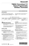
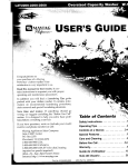
Fig.
2. Connecting
CO_M
J
the W8665A
RF Receiver
ZONE _
ZONE2
ZONES
O
O
O
O
LEg
LED
LED
LED
Module
to the
equipment.
WSG65E
h
LEDSTATES:
RAPID_v FLASHINGGREEN RECEIVIf_GINFORMATONFROM THERfqOSTAT
G_EEN OFF STANDBY,
READYTO RECEIVE_NFORMATION
ZONE
REDON SYSTE_ _HEATCOOLOR FAN}ISON
REDOFF SYSTEM(_EATCOOLORFANIISOFF
FLASHINGRED ERROR NOTRECEIVINGSIGNALFROMTHERM©STAT
AApIDJVFLAS INGRED RECEIVERIN SETUP MODE
DfPSW{TCHSETTINGS:
OFRNOTSE_U_TO RECEIVEINFORf_ATION
FRO_ATHERMOSTAT
ONmEADYTORECE_VE_NFO_MATION
FROMTHERMOSTA_
AFTER
SE_UmSCOMPLETE
ZONE1
ZONE2
ZONES
_E_UP:
_OVEDI_ SWffC_TO O_ _OS_TIO_ANDf_A_ET_ERMOSTATCALLFOR_N
NOTE_ALLOTHERT_ERMOSTA_Sf_UST
BEOFF_NO_CALLI_GIDURINGSE_UP
ZOnE I
Z_FACTORY
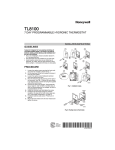
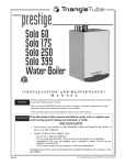
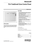
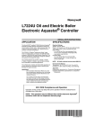
Fig. 3. Connecting
the
ZONE 2
ZONES
¥WG
R C RZ_RZ
INSTALLEDJUM_E_
W8665E
RF Receiver
LI (HOT_197S_
Module
3
to the
equipment
in a one-zone
application.
69-I630-1
W8665A,E
RF RECEIVER
MODULE
FW8665A
Q_
(_
"-'_
_
L2
_
L,NE',OLTAGE
CIRC_JLATOR
L8124E,G,L
Fig.
4. Single
zone
hot
water
heat
using
an L8124E,
G, L Aquastat.
W8665A
R8222
©
• (TV)
•
_FACTORYINSTALLEDJUMPER
CIRCULATOR
INEVOLTAGE
[_
L8124A,B,C,M
Fig. 5. Single
69-1630-1
zone
hot
water
heat
using
an L8124A,B,C,M
or L8148
4
Aquastat,
an R8222
relay
and
a transformer.
W8665A,E
RF RECEIVER
MODULE
LsA
_t
_'
_ ..................................
tt_.,.
Q0CIRCULATOR
UNEVOLTAGE
L8124/L8148
Fig.
6. Single-zone
hot water
M20_83
heat
with
cooling
using
an L8124
transformer.
5
or L8148
Aquastat,
an R8222
relay
and
a
69-I630-1
W8665A,E
RF RECEIVER
MODULE
F
i i::: i i:o:
THERMOSTAT
THERMOSTAT
COMM
ZONE /
ZONE 2
0
0
0
0
LED
LED
LED
LED
THERMOSTAT
ZONE 3
L
W8665E
LED STATES:
COMM
RAPIDLY FLASHING GREEN
RECEIVING INFORMATION FROMTHERMOSTAT
GREEN OFF
STANDBY READY TO RECEIVE _NFORMATION
ZONE
RED ON
SYSTEM (HEAT COOL OR FAN} IS ON
RED OFF
SYSTEM (HEAl COOL OR FAN} IS OFF
FLASHING RED
ERROR NOT RECEWING SIGNAL FROM THERMOSTAT
RAPIDLY FLASHING RED
RECEIVER IN SETUP MODE
DIP SWITCH SETTINGS:
OFF NOT SE%UP TO RECEIVE INFORMATION FRO_4 A THE RI_OS [AT
ON READY TO RECEIVE INFORTV_ATIONFROM THERMOSTAT AFTER
SEFUP _SCOMPLETE
ZONE I
_
ZONE 2
ZONE 3
SET-UP:
MOVE DIP SWITCH TO ON POSFION AND MAKE THERMOSTAT CALL FOR FAN
NOTE ALL OTHER THERMOSTATS MUST BE OFF (NOT CALUNG) DURING SE%UP
ZONE I
Y W
G
ZONE 2
ZONE 3
Y
Y
W
G
W
G
/_
R
C RZRZRZ
M20_8
Fig. 7. Connecting
Fig. 8. Connecting
69-1630-1
the
W8665E
RF Zone
Z_
LEAVE
JUMPER
the
W8665E
O/B
TM
Panel to the EMM-3
MiniZone
thermostat
zone COl_lrlectiorls.
DISCONNECTED
ON
EMM-3U
TM
RF Zone
Panel to the EMM-3U
up to three thermostat
zone
6
TM
Panel
to control
1H/1C
with
up three
BOARD
Zone Control
connections.
Panel
to operate
up to 2H/2C
with
W8665A,E
RF RECEIVER
MODULE
I
W8665E
ZONE I
Y
W
G
ZONE 2
ZONE 3
Y
Y W
W
G
I
I
G
/_
_'_'_±
_
_±
,J
TR/
A
FACTORY
THE
INSTALLED
THREE
JUMPER
RZ TERMINALS
ARE
INTERNALLY
24V, 40VA TRANSFORMER
CONNECTED
M20165B
Fig. 9. Connecting
the W8665E
RF Zone
Panel to the TZ-3
3H/2C with up to three thermostat
TM
ZONE I
ZONE 2
ZONE I
ZONE 2
ZONE S
w £
¥ w_
_ w _]
TotalZone®
Zone Control
zone connections.
Panel
to operate
up to
ZONE S
7-
/k_
zRzRz
oo00 oooooooo
ooooooooo
oo oooooooo
oooo oo
,_._
£._
£._
,_._ _o
T210
OAMPER
XFRM
TZ 4
Z_
FACTORY
Z_
LEAVE
Fig.
INSTALLED
O/B JUMPER
10. Connecting
JUMPER
THE
D}SCONNECTED
the
THREE
RZ TERMINALS
ON TZ-4
ARE INTERNALLY
CONNECTED
BOARD
M20572A
TM
W8665E
RF Zone
Panel to the TZ-4
3H/2C with up to three thermostat
7
TotaIZone®
Zone
zone connections.
Control
Panel
to operate
up to
69-I630-1
W8665A,E
RF RECEIVER
MODULE
W8665E
t
L8148!
END
L8124
SWITCH
T(TV)
i
V8043
L2
L/
Z'_REMOVEFACTORYINSTALLEDJUMPER
Fig.
11. Zoned
hot water
heat
using
V8043F
zone
--
I
r_I20686A
valves,
an L8148/L8124
Aquastat
and
a transformer.
7._
Y wQ
Y wG
Y wG
c RZRZRZ
N8665 r_
L8148
/ L8124
V8043F
V8043F
L2
L/
Z'_
Fig.
12. Zoned
69-1630-1
hot water
heat
REMOVE
FACTORY
and single-zone
INSTALLED
JUMPER
cooling
using V8043F
and a transformer.
8
M20687A
Zone
Valves,
and
L8148/L8124
Aquastat
W8665A,E
RF RECEIVER
MODULE
IN8665E
V8043E
• (TV)
T
L8148 / L8124
Fig.
13. Zoned
hot
water
V8043E
Z_
FACTORY
FNSTALLED
Z_
CONNECT
VE043E
YELLOW
Z_
CONNECT
VE043E
RED LEADWIRES
heat
using
V8043E
Zone
JUMPER
LEADWFRE
Valves,
TO W8665E
TO L8148/L8124
an L8148/L8124
Aquastat
and
a transformer.
7.-.
Y
Y WG
wo
¢ RZRZRZ
Y WC
W8665E
V8043E
_
V89_
V8043E
C
• (TV)
•
L8148 / L8124
Fig.
14. Zoned
hot water
heat
Z_
FACTORY ENSTALLEDJUMPER
Z_
CONNECT VEO43E YELLOW LEADWIRE TO W8665E
Z_
CONNECT VEO43E RED LEADWIRES TO L8148/L8124
and
single-zone
cooling
using
and a transformer.
9
_
L2
L/
ve043E
Zone
Valves,
an L8148/L8124
Aquastat
69-I630-1
W8665A,E
RF RECEIVER
MODULE
W8665E
R8222
r (TV)
R8222
T
L8148 / L8124
PUMP
Z_FACTORYINSTALLEDJUMPER
Fig.
15. Zoned
hot water
heat with
circulating
pumps
using
transformer.
R8222
Relays,
an L8148/L8124
Aquastat
and a
7_
N8665E
R8222
R8222
L8148 / L8124
pu[_lm
PUMP
Fig.
16. Zoned
hot water
heat and
M20691A
single-zone
cooling
Aquastat
69-1630-1
using
circulating
and a transformer.
10
pumps,
R8222
Relays,
an L8148/L8124
W8665A,E
RF RECEIVER
MODULE
SETUP
Setting Up W8665A,E to ReceiveSignals
from the T8665A Thermostat(s)
d.
NOTE:
The T8665A Thermostat(s) require(s) setup to send
signals to the W8665 Receiver Module to operate:
• The W8665A Receiver is used for single-zone
applications.
• The W8665E RF Zone
Panel is used for up to three
T8665A Thermostats for multi-zone applications.
Use Fan key to turn off fan.
At any time, if you want to stop the thermostat
from sending signals to the W8665 Receiver,
turn the DiP switch to Off. Then repeat steps 2
through 5 to set up the thermostat to send
signals to the W8665 Receiver.
TM
6.
7.
8.
IMPORTANT
Be sure the thermostat is at least five feet away
from the W8665 during setup. Maximum distance is 200 feet.
Repeat steps 2 through 5 for zones two and three.
Set System and Fan keys to desired locations.
Attach the zone number sticker, included with the
thermostat, onto the thermostat case on the inside
of the thermostat cover. See Fig. 5.
Single Zone Applications
(1 W8665A/1 T8665A)
1. Power up the W8665A and install the batteries in
the T8665A Thermostat.
2. Place the W8665A Zone 1 DiP switch to the On
position.
NOTE:
P_aceo_elabel _ns_e
eacht_efmostatdoor
The W8665A Zone 1 LED will flash.
M_342G
Fig.
Press the thermostat Fan key to On:
a. The receiver accepts the message and stores
the identity.
b. The zone 1 LED stops flashing.
c. The thermostat is now set to send signals to
the W8665A Receiver.
NOTE:
4.
At any time, if you want to stop the thermostat
from sending signals to the W8665 Receiver,
turn the DiP switch to Off. Then repeat steps 13 to set up the thermostat to send signals to the
W8665 Receiver.
Applications
(1 W8665E!Up
2.
3.
4.
to 3
W8665E Single and Multi-Stage
Operation
The first stage is energized by the themlostat.
To control multistage conventional and heat pump
systems, the W8665 must be wired to a zone control
panel that is able to control multiple stages of heat and/or
cool (such as the EMM-3U Universal Electronic MiniZone
Control Panel or TZ-4 TotalZone® Zone Control Panel).
The zone panel (not the RF panel) controls these stages
based on the number of zones calling or with a timer. See
the Zone Control Panel Instructions for more details on
how to control up to three stages of heat and two stages
of cool.
The W8665E zone 1 LED will flash.
Press the thermostat Fan key to On:
a. The receiver accepts the message and stores
the zone identity.
b. The zone 1 LED stops flashing.
c. The thermostat is now set to send signals to
the W8665E Receiver.
NOTE:
of
On a ca_l for heating or cooling from any zone, tile
thermostat sends a signal to the W8665E to bring on the
heating or cooling in that zone until the call is satisfied.
The Comm LED flashes when the W8665E receives a
signal from the thermostat in any zone to turn on the
system or approximately every ten minutes as a status
update. On a call for heating, cooling or fan, the zone
LED lights red.
Power up the W8665 and install the batteries in the
T8665 Thermostats.
Set the thermostats so no zones are calling for system or fan.
Set up each zone separately to ensure that a
unique address is used for each zone.
Place the zone 1 DiP switch on the W8665E
Receiver to the On position.
NOTE:
inside
W8665E Sequence of Operation
T8665A)
1.
for
On a call for heating or cooling, the thermostat sends a
signal to the W8665A to bring on the heating or cooling
until the call is satisfied. The Comm LED flashes when
the W8665A receives a signal from the thermostat to turn
on the system or approximately every ten minutes as a
status update. On a call for heating, cooling or fan, the
zone LED lights red.
Use Fan key to turn off fan.
Multizone
stickers
cover.
W8665A Sequenceof Operation
Set System and Fan keys to the desired locations.
NOTE:
number
thermostat
OPERATION
The word, On, and a fan blade _ appear in the
thermostat display to indicate the thermostat is
calling for the fan to turn on.
d.
17. Zone
The word, On, and a fan blade tt appear in the
thermostat display to indicate the thermostat is
calling for the fan to turn on.
II
69-I630-1
W8665A,E
RF RECEIVER
MODULE
LED Operation (See Table 4)
NOTE:
See Setting up W8665A,E Receiver Module to
Receive Signals from the T8665A Thermostat
section.
Table 4. LED Operation.
LED
LED action
Meaning
Comm
Flashes rapidly for 2-3 seconds.
Indicates device is currently receiving information from the
T8665 Thermostat.
Zones 1-3
On constantly.
Indicates system (heat, cool, or fan) is on.
Zones 1-3
Off constantly.
Indicates system (heat, cool, or fan) is off.
Zones 1-3
Flashes rapidly until signal is
received,
indicates zone is being set up to receive signals from a
transmitter (T8665 Thermostat).
Zones 1-3
Flashes continuously.
Indicates e problem receiving signals from the transmitter
(T8665 Thermostat). See Troubleshooting Guide for more
information.
69-1630-1
12
W8665A,E RF RECEIVER MODULE
TROUBLESHOOTING (TABLE 5)
Table 5. Troubleshooting
Symptom
Possible
Cause
Guide.
Action
Display does not come on.
Thermostat is not being
powered.
Check if batteries are present and installed correctly.
• if batteries are in and installed correctly, replace
thermostat.
Heating does not come on.
System on indicator
((_ = heat)is showing in
display.
Communication
completed.
End and repeat the call for heat.
Check the Comm LED and Zone LED on the W8665
while the call is being made.
• if the Comm LED does not flash when thermostat
first calls for equipment, turn that zone DIP switch
to Off. Refer to Setup section to reset the W8665.
• if the Zone LED flashes continuously, turn that
zone DiP switch to Off. Refer to Setup section to
reset the W8665.
• Check if 24 Vac is present:
• Check between R and C on W8665.
• Check between W of troubled zone and C on
W8665.
If voltage is present, troubleshoot heating system.
Cooling does not come on.
System on indicator
(>_fi = cool) is showing in
display.
is not being
Heating load at W8665 is not
connected correctly.
Thermostat is too close to
W8665.
T8665 Thermostat should be at least five feet away
from the W8665 during setup and operation.
Thermostat is too far away
from W8665.
Maximum distance between W8665 and
T8665A Thermostat should not exceed 200 feet.
Communication
completed.
End and repeat the call for cool.
Wait five minutes for the compressor delay to end.
• if the Comm LED does not flash when thermostat
first calls for equipment, turn that zone DIP switch
to Off. Refer to Setup section to reset the W8665.
• if the Zone LED flashes continuously, turn that
zone DiP switch to Off.Refer to Setup section to
reset the W8665.
• Check if 24 Vac is present:
• Check between R and C on W8665.
• Check between Y of troubled zone and C on
W8665.
If voltage is present, troubleshoot cooling system.
is not being
Cooling load at W8665 is not
connected correctly.
Thermostat is too close to
W8665.
T8665 Thermostat should be at least five feet away
from the W8665 during setup and operation.
Thermostat is too far away
from W8665.
Maximum distance between W8665 and
T8665A Thermostat should not exceed 200 feet.
Wait is displayed and the
call for cool has not started.
Compressor
effect.
Compressor protection can be set on the T8665A
from 0 to 5 minutes to prevent compressor damage
due to rapid cycling.
Wait until the compressor protection period expires.
2nd stage heat or cool (or
3rd stage heat) does not
energize.
W8665 is not wired to a TZ-4
TotalZone
Zone Control
Panel or EMM-3U Universal
Electronic MiniZone Control
Panel that controls the
multiple heat and cool
stages.
protection is in
TM
13
Wire W8665 to TZ-4 TotaiZone
Zone Control Panel
or EMM-3U Universal Electronic MiniZone Control
Panel to control multi-stage systems.
TM
Check TZ-4 TotalZone
Zone Control Panel or
EMM-3U Universal Electronic MiniZone Control
Panel and set correctly.
TM
69-I630-1
W8665A,E
RF RECEIVER
MODULE
Table
Symptom
Fan does not come on with
a call for electric heat.
5. Troubleshooting
Possible Cause
Guide.
Action
Electric heat setting is not
configured.
Set thermostat installer Setup Number 2 to 1 for
electric heat. See thermostat instructions for details.
Fan load at W8665 is not
connected correcfiy.
Check that 24 Vac is present between R and C.
Check that 24 Vac is present between G and C.
If voltage is present, troubleshoot system.
69-1630-1
14
W8665A,E
RF RECEIVER
MODULE
FCCID: CFS8DL5800TSTAT
CANADA:
1748A12113
This device complies with Part 15 of the FCC Rules. Operation is subject to the following two conditions:
(1) This device may not cause harmful interference, and
(2) This device must accept any interference
received, including interference
that may cause undesired operation.
FEDERALCOMMUNICATIONSCOMMISSION(FCC) STATEMENT
This equipment has been tested to FCC requirements
following statement for your information:
and has been found acceptable for use. The FCC requires the
This equipment generates and uses radio frequency energy and, if not installed and used properly; that is, in strict
accordance with the manufacturer's instructions, may cause interference to radio and television reception. It has been
type tested and found to comply with the limits for a Class B computing device in accordance with the specifications in
Part 15 of FCC Rules, which are designed to provide reasonable protection against such interference in a residential
installation. However, there is no guarantee that interference will not occur in a particular installation, tf this equipment
does cause interference to radio or television reception, which can be determined by turning the equipment off and on,
the user is encouraged to try to correct the interference by one or more of the following measures:
•
•
•
•
•
If using an indoor antenna, have a quality outdoor antenna installed.
Reorient the receiving antenna until interference is reduced or eliminated.
Move the radio or television receiver away from the receiver/controL
Move the antenna leads away from any wire runs to the receiver/control.
Plug the receiver/control into a different outlet so that it and the radio or television receiver are on different branch
circuits.
If necessary, the user should consult the dealer or an experienced radio/television technician for additional
suggestions. The user or installer may find the following booklet prepared by the Federal Communications Commission
helpful:
"Interference Handbook"
This booklet is available under Stock No. 004-000-00450-7
20402.
from the US Government Printing Office, Washington, DC
The user shall not make any changes or modifications to the equipment unless authorized by the Installation
Instructions or User's Manual. Unauthorized changes or modifications could void the user's authority to operate the
equipment.
15
69-I630-1
W8665A,E
RF RECEIVER
MODULE
Honeywell
Automation
Hoile_
1985 Dougla_
Ooldei_
alld
(ontrol
Solutio_ls
Driw
North
35 DyilamlC
55422
Sca_oiough,
M 1V 4Z9
e[1
Valley',
69-1630-1
H one)_,, ell Limir_d-H
MN
G.H.
Rev
9-03
oile_._ _11Li1_litee
Drive
Ontario
_
paper
lO%
Printedcontaining
in U S A at
on le_st
recycled
post ¢onsume_ paper fibers
www.honeywelLcom/yourhome