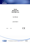
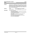
1
HANGZHOU HELON TECH LTD.
U S E R G U ID E
VG-2000 GPRS/CDMA/3G
Vehicle GPS Tracking Device
Preface
VG-2000 GPS Tracking Device is the updated version based on
GPS-GSM/GPRS/CDMA/3G, after years of R&D and marketing experiences.
Helon has the complete GPS product line providing the accurate positioning of
the moving target. The superb two way data communication technology of GPS
and GMS enables the monitoring center to better manage the jobs of both
vehicle and personnel.
The Helon GPS device are best used for Public security, armored vehicle, fire
fighter, Ambulance, Postal service, Cargo Transportation, Government Service,
Civil Transportation vehicle, Mines, Chemical plant, Military, etc. For almost
anything that can be imagined.
http://gps571.com
[email protected]
22/F, Bldg B, Zhong Lian Mansion, 218 Moganshan Road, Hangzhou, Zhejiang Province,China 310012
HANGZHOU HELON TECH LTD.
1. Product Preview
1) The System Structure
Schematic:
The package:
JY_VG2000B
GPS Monitor
(optional)
Screen
(optional)
Phone
(optional)
GPS Antenna
GSM Antenna
http://gps571.com
[email protected]
22/F, Bldg B, Zhong Lian Mansion, 218 Moganshan Road, Hangzhou, Zhejiang Province,China 310012
HANGZHOU HELON TECH LTD.
2、Performance indicators
2.1 Electrical Specifications
◇
Power Interface:
12V or 24V
◇
Current:
<200mA(Active Status)
◇
Speed Accuracy
<=0.2m/s
◇
Cold startup positioning time
<120s
Warm startup positioning
<60 Sec.(95% possibility)
◇
time
◇
Positioning accuracy
25m (no SA, no difference)
◇
Dynamic characteristics
not less than 4g
◇
Frequency Range
GSM 900/1800 MHz; GPS 1575.42 MHz
◇
Telecommunications range
GSM SMS enabled entire network
2.2、Environmental indicators
◇
Host working temperature
-20℃~+55℃
◇
Storage temperature
-40℃~+70℃
◇
Relative Humidity
93% (Not condensed)
◇
Antenna working temperature
-30℃~+75℃
◇
Storage temperature
-40℃~+90℃
◇
Cable working temperature
Not more than 85℃
2.3、Physical size and weight:
Size: 102mm x 80mm x 28mm Weight:300g
3. Features
3.1 Main features
◇
GPS Positioning
◇
GSM car phone
◇
SMS Inter-transmission
◇
Infrared remote control dialing
◇
Emergency messaging
◇
◇
Timely delivery of alarm
information and monitoring
Remote wireless control of multiple
output
◇
Self-protection function for device over
voltage
Δ :Indicating LCD screen function
http://gps571.com
[email protected]
22/F, Bldg B, Zhong Lian Mansion, 218 Moganshan Road, Hangzhou, Zhejiang Province,China 310012
HANGZHOU HELON TECH LTD.
Installation and User Guide
1. Installation and connection instructions
Recommended installation location as shown components, different models
have different installation methods. (Car for example here)
Image 2-A Installation diagram
Image 2-B Physical Installation Map
GPS Antenna
Alarm button
GPS Device Power cable
The Phone
The Screen
http://gps571.com
[email protected]
22/F, Bldg B, Zhong Lian Mansion, 218 Moganshan Road, Hangzhou, Zhejiang Province,China 310012
HANGZHOU HELON TECH LTD.
1.1 Installation and Wiring
The GPS Machine can be installed relatively hidden in the vehicle trunk corners, while
the power cord that came with the system, the big screen cable and GPS, GSM
antenna, and other control cables toward the driving cabinet, then fix the GPS host
machine. Pay attention to the moisture and shock!
GPS antenna fixed location should be selected in front, rear windshield, the location as
close to the bottom of the windshield, and to ensure the level of the antenna; it is also
important that the GPS antenna is in the most possible free area of no interfering
objects to the GPS antenna.
GSM antenna should not be surrounded by metal objects, if objects from above the
antenna or too close to the GSM antenna, it may affect the normal signal reception,
resulting in decreased accuracy of vehicle terminal, therefore, it requires:
◇ As far as possible away from the objects
◇ Outside of the radar beam
◇ At least 4 meters to the VHF / HF / MF transmitting antenna
The screen connecting thread can be placed to the fixed display large screen. The
Power cord can go to the power fuze box in the driver's cab.
1.2 Cable Connections.
Image 3 Connection Diagram
http://gps571.com
[email protected]
22/F, Bldg B, Zhong Lian Mansion, 218 Moganshan Road, Hangzhou, Zhejiang Province,China 310012
HANGZHOU HELON TECH LTD.
1.2.1
The GPS Main Machine
GSM Antenna
Connector B
Connector
SIM Card
GPS Antenna Connector
Indicator Light
Connector A
Image 3_A The GPS Machine physical map
1.2.2 A/B Connection of the connectors be referred to the following diagram:
2
20
2
12
1
19
1
11
Connectors A
Connectors B
Image 3_B
1.2.3
The Connection Diagram
referring to Image 3_B, The wiring instructions of all connectors.
Connector A: (the function of each cable can be referred to the explanations of the
Connector B Appendix.
1. Connecting the red ① and black ② cables to the cable panel of the car battery.
(please be very careful not to connect the wrong cable of the battery) !
2. Connecting the yellow ③ cable to car ignition terminal, it must be controlled by
the car key.
3. Connecting A1_Z socket to the battery A1_T plug.
4. Connecting A2_Z socket to the Anti Theft Device Plug (Called “Tie Jian Jun” - A
Chinese anti theft device model). ( Details of Tie Jian Jun cable connections can
be referred to installation manual of the optional accessories in Appendix A.)
5. Auto Alarm is for the connectors terminal for other applications which require
auto alarm functions.
6. Connecting A3_Z socket to the alarm system button A3_T plug (if reverse
connection, after starting up the device, the indicator will not light on when
pressing the alarm button). (Optional)
7. This socket is optional for other reserved cables, it can be used for other
applications when needed.
http://gps571.com
[email protected]
22/F, Bldg B, Zhong Lian Mansion, 218 Moganshan Road, Hangzhou, Zhejiang Province,China 310012
HANGZHOU HELON TECH LTD.
Connector B wiring instructions:
1. This socket has 2 plugs, B1_Z (RJ45) crystal head is to connect the screen or hand
held device. (optional)
2. Connecting B2_Z to the car amplifier B2_T plug, this is to control the devices
connecting or controlling the car amplifier.
See details in Connector B Appendix
User Manual
2.1 the main box
2.1.1 Power on and off.
This device starts on togeth with the car ignition. It will be off when car ignition
is turned off. If at the time of the car ignition being turned off, there is the
emergency alarm situation, this device will then continue in the working status,
until the emergency alarm is cancelled. .
In normal off status, when there is an emergency alarm situation, the device
will auto start up.
2.1.2 Alarming
When emergency situation occurs, or in need of assistance, help, hand press
the Alarm button (red), the terminal device will instantly send alarm signals to
the Control Center. Auto Alarm will be triggered on if car door, window, or
trunk are not intentionally broken in or opened, while the user is not at scene.
The alarm alert will be instantly sent to the control center, to alert the user of
the event.
2.1.3 Output Control
The system has 7 output controls. Each control can be adjustedto the
customer’s needs based on the software customs definitions.
2.1.4 Other Functions
All other functions can be obtained through the hand-held device or monitor
screen.
http://gps571.com
[email protected]
22/F, Bldg B, Zhong Lian Mansion, 218 Moganshan Road, Hangzhou, Zhejiang Province,China 310012
HANGZHOU HELON TECH LTD.
3. Diagnosis of Common Issues
Issue
Reasons
Vehicle
GPS Antenna is interfered or
Drive to an area without obvious high
shielded by obstacles, or too
rise obstacles; wait for the GPS device
close to high rise buildings.
picking up correct data.
Antenna is not installed correctly.
GPS antenna must be leveled in a wide
Position is not
accurate
Method
angled space.
Antenna has faulty connection.
Wind the antenna to position, and try
again
The BNC of the device is
Make sure BNC plughas the reading of
malfunctioning.
5V±0.5
GPS Antenna is Malfunctioning.
Replace the antenna
Alarm signal is
Alarm Button is damaged
Check external device connection (e.g.
not sent or
Alarm Connection Port is
Anti Theft Device).
alarm signal is
malfunctioning
not sent
Alarm Method is not chosen
Check Control Center Settings for the
continuously.
correctly
alarm method.
GPS device is
SIM card is not correctly
Check SIM card and insert again.
set
installed.
up,
but
does not work
GPS cables are not connected
at all.
correctly
Device has no
GSM Signal
Check GPS cable connections.
GPS device is malfunctioning.
Replace GPS device
Vehicle is in the blind spot area.
Drive to the area that has the GSM
reception signals.
http://gps571.com
[email protected]
22/F, Bldg B, Zhong Lian Mansion, 218 Moganshan Road, Hangzhou, Zhejiang Province,China 310012
HANGZHOU HELON TECH LTD.
4. Maintenance
- This GPS device is running at normal DC 9∽36V±0.5V. Over or under that level, this
device will be triggered the auto protection setting and cut off the power automatically, to
avoid possible damage. Before device installation, or at the event of auto power off, user
shall check the power system to make sure it is working properly. The recommended
working voltage is 12V, or 24V. User shall strictly follow the operation instructions of this
manual. Device damage due to the user’s Improper installation or use is not covered by
product warranty.
- The device positioning requires GPS signal receiption, proper and correct antenna
connection is very important, user shall make sure the antenna is correctly and properly
connected and be sure to place and leveled the antenna in an area without other Radio
interference.
- Temperature range for the device is between -20℃ and 55℃, lower or above this range
will cause the device malfunction, and user shall not use the device at this temperature.
- When power is on, DO NOT UNPLUG the GPS and GSM antenna, or else the device can be
damaged.
-
Do not use the device at gas station, near flammable gas or volatile chemicals.
-
Do not use the device near medical therapy apparatus or equipment.
-
Follow your local rules or laws when using your device.
- Recommended wire protection is to use the fire resistance pipe or stainless pipe ( it
depends on the installation environment).
- TO ensure the device working properly and avoid damage to the device, this VG-2000
GPS tracking model requires all accessories approved by the company.
-
Contact your local dealer or distributor when needed.
Disassembling this device avoids all warranty. DO not do it !
http://gps571.com
[email protected]
22/F, Bldg B, Zhong Lian Mansion, 218 Moganshan Road, Hangzhou, Zhejiang Province,China 310012
HANGZHOU HELON TECH LTD.
Appendix A
Packaged Accessories and instructions:
GPS Antenna size:58mm×48mm×15mm (L x W x H)
Features: 20dB; 1575.42MHZ
GSM Antenna size:100 mm (L x W x H)
Features: 2dB; 900/1800 MHZ
http://gps571.com
[email protected]
22/F, Bldg B, Zhong Lian Mansion, 218 Moganshan Road, Hangzhou, Zhejiang Province,China 310012
HANGZHOU HELON TECH LTD.
Appendix B
VG-2000 Connectors Definitions
Connector A
PA1---------GND
Negative Power
PA2---------+12V
Positive Power
PA3---------LALARM(Low Alarm) Emergency Alarm
PA4---------POWCTR
ACC
PA5---------GND
Extension Serial Ports
PA6---------TX(TX232)
Extension Serial Port Stream
PA7---------HALARM(High Alarm) Anti Theft Alarm, High efficiency Alarm,
PA8---------RX(RX232)
PA9---------OUT1
and input.
Extension Serial Ports Receiving
Gas /Power supply off (after 80 pulse output)
PA10--------OUT2
Forward/Reverse Control output
PA11--------OUT3
Door Lock Control (default set to “High” output, door open to 1 second “Low” pulse.
PA12--------OUT4 Door Close Control. (default set to “High” output, door open to 1 second “Low” pulse.
PA13--------OUT5 (BAKLIN,low voltage alarm with external battery checkup.(High sensitive alarm)
PA14~PA20
---
For internal use only (programming purpose)
Connector B:
PB1---------+5V
PB2---------GND
PB3---------Monitor screen (or hand held device) serial port receiving (RX)
PB4--------- Monitor screen (or hand held device) serial port sending (TX)
PB5---------First channel Audio Input+
PB6--------- First channel Audio InputPB7---------First channel Audio Output +
PB8--------- First channel Audio Output PB9---------Second Channel Audio Input+
PB10---------Ground
PB11-------- Second Channel Audio Output+
PB12---------Ground
2
20
2
12
1
19
1
11
Connector A
Connector B
http://gps571.com
[email protected]
22/F, Bldg B, Zhong Lian Mansion, 218 Moganshan Road, Hangzhou, Zhejiang Province,China 310012
HANGZHOU HELON TECH LTD.
Disclaimer:
Hangzhou Helon Tech Ltd. complies to the principles of long term development strategy,
the company reserves the rights of the descriptions in this manual with regard to the GPS
tracking device, and accessories, LCD display, hand held communication device, software
and hardware upgrade, improvements, without prior notice. There might be the
discrepancies in the printed manual.
This manual is not the legal contract, it is simply the product user manual for reference
purpose. The ultimate interpretation of this manual goes to Hangzhou Helon Tech Ltd.
Technical support: [email protected]
Hangzhou Helon Tech Ltd.
2010.03.30
http://gps571.com
[email protected]
22/F, Bldg B, Zhong Lian Mansion, 218 Moganshan Road, Hangzhou, Zhejiang Province,China 310012