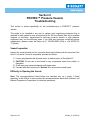
1
Lenntech
[email protected]
www.lenntech.com
Tel. +31-15-261.09.00
Fax. +31-15-261.62.89
Bekaert Progressive Composites
PROTEC™
Pressure Vessels
Users Manual
www.bekaert.com/progressivecomposites
Table of Contents
Section
Description
Page
1
Intended Use
3
2
Precautions
4
3
Vessel Installation
6
4
Multiple Porting Recommendations
9
5
Piping Recommendations
13
6
Pre-Pressurization Checklist
15
7
Preventative Maintenance
17
8
Recommended Spare Parts
18
9
Troubleshooting
19
10
Head Removal Procedure
24
11
Head Rebuilding Procedure
26
12
Head Loading Procedure
27
13
Side Port Seal Replacement Procedure
32
14
Paint Repair Procedure
34
15
Preservation Precautions
35
16
Factory Contact Information
36
Page 2 of 36
901002_A, 4/27/2010
Section 1
Intended Use
The Pressure Vessel is designed for continuous use as a housing for membrane
elements. Vessel has been designed to meet the standards of the American Society of
Mechanical Engineers (ASME), Boiler and Pressure Vessel Code, Section X. At an
additional cost, vessels can be inspected during fabrication by an ASME Authorized
Inspector and Code stamped. Vessel must be installed, operated and maintained using
good industrial practice and following the precautions listed in order to help assure safe
operation and a long service life. Misuse, improper installation or operation may result in
severe bodily harm or property damage and will void the vessel warranty. Therefore,
review and follow the safeguards listed below before placing the vessels into service.
The filament-wound reinforced plastic shell of this vessel must be allowed to expand
under pressure. Any undue restraint at the support points or piping connections can
cause non-repairable leaks to develop in the shell. This vessel must not be subjected to
excessive stress caused by bending moments acting at the side ports in the fiberglass
shell. The end closures and side ports of the vessel must be kept dry and free of
corrosion at all times. Failure to do so may result in deterioration that can lead to
catastrophic failure of the vessel heads. When requested, Bekaert Progressive
Composites will assist the purchaser in determining the suitability of this standard
vessel design for their operating environment. However, the final determination
including the evaluation of the materials of construction for use in the specific corrosive
environment shall be the responsibility of the purchaser. Alternate materials of
construction may be available on special order.
Page 3 of 36
901002_A, 4/27/2010
Section 2
Precautions
Follow all instructions.
Failure to take every precaution listed will void the vessel warranty and may result in
vessel failure.
Mount shell using furnished hardware.
Following the recommended span(s), mount the vessel on saddles provided. Tighten
straps to 1 ft-lb (1.4 N-m) maximum.
Align the side ports with the manifold.
Center each vessel with the manifold and correct the causes of misalignment for each
and every vessel.
Use flexible type groove-end pipe couplings.
Use Victaulic™ or similar flexible groove-end couplings adequate for the intended
pressure following the manufacturer specifications. Allow the maximum possible gap
permitted by the coupling device, in order to maximize flexibility.
Maximize the connection flexibility.
Position the vessel and the piping so that the vessel can grow in length and diameter
under pressure without any undue restraint. DIA = 0.014” (0.4 mm) and L = 0.25”
(6.4 mm) for a length code –7 vessel. This is especially true for Permeate piping where
it is mandatory to maintain maximum flexibility.
Provide overpressure protection.
Set the safety device at not more than 105% design pressure.
Inspect end closures and side ports regularly.
Replace damaged or deteriorated components and correct the cause of any deviation.
Relieve system pressure before working on the vessel.
Working on vessels that are under pressure may result in bodily harm and/or property
damage.
Never support other components with the vessel.
Hanging piping manifolds or supporting other components with the vessel may result in
vessel damage. DO NOT allow the Feed / Concentrate ports or the Permeate ports to
hold the weight of manifolds. Always use the frame to secure manifolds in a manner that
does not pull on these ports.
Do not over tighten the Permeate Port connection.
Tightening the connection more than one turn past hand tight will damage the port.
Avoid movement on the permeate piping not to produce stress on the permeate port.
Ensure that the Thrust Ring is installed downstream.
Operating without a thrust ring may cause membrane damage.
Shim the membranes.
Shim carefully the column of membranes to minimize movement of elements.
Double check end closure installation.
Ensure that retaining system is in place and fully seated.
Page 4 of 36
901002_A, 4/27/2010
Never operate the vessel in excess of its ratings.
This practice will void the vessel warranty, shorten vessel life and could lead to bodily
harm or property damage.
Do not operate the vessel permeate port over 125 psi (8.6 bar).
Permeate pressure in excess of 125 psi (8.6 bar) must be approved by the factory prior
to operation.
Operate the vessel in only positive pressure applications.
This vessel is not designed for vacuum conditions.
Flush the vessel before system shut down.
Some feed waters may cause corrosion under static conditions. Flushing with noncorrosive permeate is recommended.
Operate the vessel within the recommended pH range.
The vessel is designed for continuous use at a pH of 3-11 and for intermittent cleaning
(less than 30 min. at a pH of 2-12). The use of chemical additives, such as sodium
bisulphate or others, may impact the pH and must be continuously monitored and
controlled. Please see Section 15 for further precautions when using chemicals.
Do not install the vessel in direct sunlight.
*Please inform the factory when continuous operating temperature is less than
45°F (7°C).
Page 5 of 36
901002_A, 4/27/2010
Section 3
PROTEC™ Pressure Vessels
Vessel Installation
Proper vessel inspection, handling and installation are important to help ensure a long
vessel life. This guide should be followed during vessel installation by the party
responsible for the installation of the vessels into the system. However, following this
guide does not relieve the purchaser from full responsibility for proper inspection,
handling and installation of the vessel. Damage due to improper handling or installation
shall be the sole responsibility of the purchaser.
Read this entire guide carefully. Vessel misuse, mishandling or corrosion damage can
result in a mechanical failure that can cause property damage, personal injury or even
death. Should any information provided in this guide not agree with the system suppliers
recommendations, please call Bekaert Progressive Composites at +1 760-599-4800
(USA) or +34 94-674-03-12 (Spain) for clarification.
Handling, Receiving and Inspection
Fiberglass pressure vessels are very rugged and are the choice of the industry for
membrane applications. They are designed to operate safely over a long service life
when they are handled and installed correctly. However, failure to do so may result in a
malfunction or catastrophic failure while in service. To help prevent this possibility,
please follow the precautions listed below:
1) Never lift or move a vessel by placing something inside the vessel bore. The
inside surface is designed and intended only for membrane installation and
removal. Lifting the vessel in this careless manner may permanently damage the
vessel.
2) DO NOT scratch the inside surface of the vessel. This is especially true just
inside the vessel bore where the head components must seal to the inside of the
vessel.
3) DO NOT place tools or anything other than Membranes inside the vessel to avoid
scratching the inside surface of the vessel.
4) DO NOT drop the vessel or allow it to hit other objects. If this happens, damage
may be masked due to the durable polyurethane coating, thus hiding a potentially
damaged vessel that may fail while in service.
5) DO NOT apply any undue stress at the shell. While the vessel can handle a
small amount of misalignment, applying any undue stress may shorten the vessel
life and lead to leakage while in service.
6) Before using a forklift or a crane to handle the vessels, either add padding to the
forks or to the vessel wall to prevent any damage to the shell. Scratching or
gouging the outside of the vessel can be prevented by proper handling.
Page 6 of 36
901002_A, 4/27/2010
Impact Damage
Damage to the exterior of the vessel may lead to early failure. Any damage received in
shipment must be reported to the shipping company immediately upon receipt. Minor
damage that goes no deeper than the paint will be acceptable for adequate
performance, however deep gouging should be inspected prior to the vessel being
placed into service. When in doubt, please contact the Customer Service Department at
Bekaert Progressive Composites at +1 760-599-4800 (USA) or +34 94-674-03-12
(Spain).
Mounting the Shell
This section is written to address the mounting of all PROTEC pressure vessels. If you
are mounting vessels for the first time, please refer to Section 5 for piping
recommendations.
Installation
1)
2)
3)
4)
5)
Before determining a final position for the vessel skid, make sure that adequate
room is provided to access both ends of the vessel. Elements are installed from
the feed end of the system and then removed from the opposite (downstream)
end of the system.
Follow all the applicable guidelines on handling, receiving and inspection as
noted earlier.
NOTE: It is important that each vessel is placed in a way to minimize any strain
induced from the system piping that connects the vessel to a header or other
system connection. Normally we suggest that each vessel be centered on the
frame with the feed/concentrate ports located in such a way that the piping
connections can be easily made without any undue stress. Plumbing
components attached to the permeate port or head assembly must be
independently supported.
Set the vessels on the urethane support saddles positioned directly on the
system frame at the “S” dimension found on the Engineering Drawing. Ideally,
the frame should already be drilled for mounting the vessels. The holes in the
frame should be drilled to the dimension found on the Engineering Drawing.
Bekaert always recommends for long vessels to use 3 saddles and only 2
straps to minimize shell stress.
Connect the vessels to the manifolds or to the next vessel while adjusting each
shell and manifold for minimal misalignment at each end. The port to manifolds
or port to port clearance should be set at the flexible connectors’ Maximum
recommendations. This dimension is usually 0.125 inches (3.175 mm). Double
check with your coupling supplier for this value. The flexible connector should
be able to be tightened without experiencing any binding. Secure the manifolds
of the system and the vessels only after completing this important alignment
procedure.
Page 7 of 36
901002_A, 4/27/2010
6)
WARNING: Do not mount the vessels in any way that will restrict the growth of
the vessel. Limiting expansion by rigidly mounting the vessels will not allow for
proper vessel growth under pressure and affect vessel life. For expansion
requirements, please see Section 2.
7) Connect the vessel straps to the system frame by positioning the screws
through the frame and threading them into the bar nut located on the vessel
strap. Tighten straps until finger tight.
8) Finish any piping and alignment that has not been completed following the
alignment procedure noted above.
9) Using a wrench, tighten the strap screws one additional full turn. This should
result in 0-1 ft-lb (0-1.4 N-m) of torque. If in question, repeat the procedure and
measure the torque with an appropriate tool.
10) CAUTION: DO NOT over tighten straps to avoid vessel damage.
11) NOTE: PROTEC straps are designed to secure the vessel during operation.
They have not been designed to handle any and all loads that may occur based
on any unforeseen mounting condition. Appropriate evaluation should be
employed to ensure that and factors such as transit, non-traditional mounting
and system design. PROTEC straps are not designed to handle the weight of
the vessel. For skid transportation the straps must be tightened to avoid any
vessel movement but must be loosened for operation.
12) Strap assemblies are designed for horizontal positioning only.
Page 8 of 36
901002_A, 4/27/2010
Section 4
PROTEC™ Pressure Vessels
Multiple Porting Recommendations
This guide is not intended in any way to replace good engineering judgment that is
required for safe operation over a long service life. We recommend that only a qualified
engineer or mechanic, experienced in servicing pressure vessels or high pressure
equipment carry out the following tasks. If you have any questions concerning proper
maintenance, please contact the factory at +1 760-599-4800 (USA) or +34 94-674-0312 (Spain).
Multiple port vessels are those specified by the user to have more than one highpressure port per end. This feature allows vessels to be directly connected together
allowing water to flow through one vessel into another. This piping method has become
an acceptable way to provide superior system designs while reducing system costs.
While the thought of directly bolting vessels together is easily understood, there are
several guidelines that must be followed in order to have a good long-term system
design. These are as follows:
Flow-balance the system.
When supplying feed water from one side of the vessels, take the concentrate from the
opposite side. This will prevent more water from flowing through the first vessel and
starving the second and third. This practice will help equalize feed flow to each vessel.
Minimize pressure drop.
As water passes through each vessel, a pressure drop occurs. This will result in the last
vessel in a connected pass receiving less pressure than the first. Increasing port size
reduces this effect.
Optimize the water velocity through the ports.
The speed of the water through the ports should be kept within a reasonable range to
ensure proper long-term performance (typically 5-15 ft/sec. (1.5-4.5 m/sec.)) Speeds
that are too fast will result in port erosion while speeds that are too slow will promote
corrosion.
Avoid the temptation to use smaller ports.
Even though the thought of adding on an extra vessel with small ports sounds
reasonable, it can result in a pressure drop problem.
Page 9 of 36
901002_A, 4/27/2010
Take caution when using more than one port size.
Changing ports sizes in a second or third pass requires careful evaluation of pressure
drop that can affect system performance.
Check with your membrane supplier.
It is a good idea to let your membrane supplier evaluate the performance of your
proposed system.
Don’t assume that we endorse the use of multiple ports for your system.
Just because vessels can be ported together does not make them the best choice for
your system. Bekaert Progressive Composites is not responsible for the misapplication
of the multiple port option.
Page 10 of 36
901002_A, 4/27/2010
Page 11 of 36
901002_A, 4/27/2010
Page 12 of 36
901002_A, 4/27/2010
Section 5
PROTEC™ Pressure Vessels
Piping Recommendations
This guide is not intended in any way to replace good engineering judgment that is
required for safe operation over a long service life. We recommend that only a qualified
engineer or mechanic, experienced in servicing pressure vessels or high pressure
equipment carry out the following tasks. If you have any questions concerning proper
maintenance, please contact the factory at +1 760-599-4800 (USA) or +34 94-674-0312 (Spain).
PROTEC™ pressure vessels are the most durable side port vessel available today.
Unlike vessels with less durable designs, connecting PROTEC side ported vessels to
manifolds or to each other is easily done if some very basic rules are followed. These
are as follows:
Use two flexible Victaulic™ connections when manifold accuracy is questionable.
The tolerance required for side-ported vessels should be a total per port of 0.030” (.76
mm). For retrofitting side-ported vessels into older systems or when manifold tolerances
can simply not be guaranteed, the two-connection method is the safest approach.
Use a single flexible Victaulic™ connection when manifold accuracy is not a
problem.
This is possible when manifold to vessel misalignment can be held to within 0.030”
(0.76 mm) in any direction. However, it is important to note that these flexible
connections allow angular but not lateral misalignment. Therefore, any misalignment
must be kept to a minimum.
Use intermediate Victaulic™ connections in the manifolds when required.
This practice allows more flexibility in the system resulting in easier to install manifolds.
Center the vessel between the manifolds.
This is very basic but commonly overlooked. If the port on one end is directly aligned
with the manifold and the opposite end is off by a small distance, centering the vessel
so that the small distance is equally divided between each end before tightening the
straps allows each end to handle half this distance rather than all at one end. Do this
with each vessel to reduce stress on the ports.
Allow one manifold to float.
In some systems, the manifold can be connected to the vessels and supported by the
floor but allowed to float in the axial direction to provide room for vessel growth under
pressure.
Page 13 of 36
901002_A, 4/27/2010
Let the manifold span be longer than the vessel span.
Remember that the vessel will grow in length under pressure, see Section 2. Setting
the manifold span to the maximum tolerance is another way to provide room for vessel
growth under pressure.
Check each connection for acceptable misalignment.
By installing the Victaulic™ connection without the gasket and drawing the bolts snug,
the connector should be able to rotate by hand. On some systems this test may not be
practical. In these cases the Victaulic™ connections must be able to be tightened
without the need of excessive force. Force would indicate a major misalignment that
could damage the vessel. When in doubt, contact the factory.
Ship skids without Victaulic™ couplings to prevent damage.
We recommend that prior to the shipment of preassembled skids, the Victaulic™
couplings be removed and shipped in a separate box. The gasket should remain in
place for easy assembly at the destination.
Page 14 of 36
901002_A, 4/27/2010
Section 6
PROTEC™ Pressure Vessels
Pre-Pressurization Checklist
Danger – High Pressure Device
The operation of this vessel may cause loss of life, severe bodily harm and/or property
damage if not installed correctly and maintained throughout operation. Read,
understand and apply all the guidelines given before attempting to open, close, service
or in any way operate this vessel.
Failure to follow these guidelines, observe every precaution and use good engineering
judgment may result in a malfunction that could result in the explosive failure of a vessel
head or side port.
Misuse, incorrect assembly or the use of damaged or corroded components in the end
closure or vessel side port can result in the components failure.
We recommend that only a highly qualified engineer or mechanic experienced in
serving high pressure equipment open, close and service this vessel.
The checklist alone does not include all the details needed for safe vessel operation.
Use the checklist each time any service operation is carried out to ensure that each step
is completed before pressurizing the vessel.
Page 15 of 36
901002_A, 4/27/2010
PROTEC™ Pressure Vessels
Pre-Pressurization Checklist
Membrane Elements
Installed per manufacturers recommendations.
Feed flow direction correctly noted and elements correctly oriented.
Element Interface
Adapters installed at both ends of element column.
Thrust Cone installed downstream. (Concentrate or brine end) of the element
column.
Head
All components in as-new condition clean and free of damage or corrosion.
All components properly assembled with new freshly lubricated seals as
required.
Head stamped with proper rating for system.
Head seal is free of dirt, grit, dust, etc.
Head assemblies are properly shimmed to avoid membrane shifting.
Head Assembly Interlock (PRO)
Retaining ring groove at each end of shell clean, free of corrosion with insert ring
in sound condition.
All components in as-new condition; clean and free of damage or corrosion.
Retaining Ring is fully seated in the retaining ring groove.
Head Assembly Interlock (BPV)
Locking segment groove at each end of shell clean, free of corrosion with locking
segments in sound condition.
All components in as-new condition; clean and free of damage or corrosion.
Locking segments are fully seated in the locking segment groove and retaining
screws are tight.
Side Ports and Piping Connections
Properly aligned (strain-free) and secured.
Leak and corrosion free.
Page 16 of 36
901002_A, 4/27/2010
Section 7
PROTEC™ Pressure Vessels
Preventative Maintenance
Preventative maintenance is essential to help ensure the safe operation of Bekaert
Progressive Composites PROTEC™ pressure vessels.
Attention to each point listed below will enhance long-term use and provide a vessel
that is easier to open, close and service. Please use the list below as well as sound
engineering judgment when it comes to vessel maintenance. If you have any questions
concerning proper maintenance, please contact the factory at +1 760-599-4800 (USA)
or +34 94-674-03-12 (Spain).
For suggestions on cleaning corrosion deposits from the vessel or head, please refer to
Section 9.
Prevention Checklist
⇒ End closures. Inspect for components that have deteriorated. Replace as
needed.
⇒ Side Ports. Inspect for leakage or any signs that the locking system of the
side port may have deteriorated. This may require the removal of the port
or port seal to determine locking components condition. Replace as
needed.
⇒ Keep external head assembly components as dry as possible.
⇒ Keep all side ports dry and free of leaks that can cause corrosion.
⇒ DO NOT TOLERATE LEAKS.
CAUTION:
Any leakage indicates a potentially dangerous condition. Failure to eliminate
leakage may void the vessel warranty and could result in vessel failure.
Page 17 of 36
901002_A, 4/27/2010
Section 8
PROTEC™ Pressure Vessels
Recommended Spare Parts
Many system operators commonly request our input as the supplier when it comes to
the amount of recommended spare parts required for our pressure vessels. This
question is sometimes difficult to answer as we can not predict any abuse that the
vessel may see during start-up and we have no information concerning the operating
environment. However, we can provide a good faith estimate of what a supplier may
want to have on hand to ensure proper system performance. The following spare parts /
consumables list is for start up and the first two years of operation. These components
are available for sale from Bekaert Progressive Composites. If you have any questions
concerning spare parts / consumables, please contact the factory at +1 760-599-4800
(USA) or +34 94-674-03-12 (Spain).
Spare Parts
Number of vessels
1-50
51-100
101-250
251-500
500 & up
2
2
3
4
4
6
5
8
6
10
2
4
6
8
10
1
2
1
6
10
10
10
10
2
3
2
8
10
10
10
10
4
4
4
10
20
20
20
20
6
5
6
10
20
20
20
20
8
6
8
10
25
30
30
30
Part Name
Entire vessel head
Head Locking Ring
(PRO)
Head
Locking
Segment
sets
(BPV)
Permeate Port
Adapter
Thrust Cone
Side port seal
Head Seal
Permeate Port Seal
Adapter Seal
PWT Seal
Page 18 of 36
901002_A, 4/27/2010
Section 9
PROTEC™ Pressure Vessels
Troubleshooting
This section is written specifically for the troubleshooting of PROTEC™ pressure
vessels.
This guide is not intended in any way to replace good engineering judgment that is
required for safe operation over a long service life. We recommend that only a qualified
engineer or mechanic, experienced in servicing pressure vessels or high pressure
equipment carry out the following tasks. If you have any questions concerning proper
maintenance, please contact the factory at +1 760-599-4800 (USA) or +34 94-674-0312 (Spain).
Vessel Inspection
Inspect the vessel at each end for corrosion which may interfere with the removal of the
head. If corrosion if found or suspected, proceed as follows:
1) Loosen any deposits with a brush and or a medium piece of Scotchbrite™.
2) CAUTION: Do not use a wire brush on any components made from plastic, or
fiberglass.
3) Flush away any loosened deposits with clean water.
4) Proceed with the instructions in Section 10 to remove the vessel head.
Difficulty in Opening the Vessel
Note: The recommendations listed below are intended only as a guide. If head
assembly is still difficult to remove after the recommendations have been followed, call
Bekaert Progressive Composites for technical assistance.
Page 19 of 36
901002_A, 4/27/2010
Retaining Ring (PRO)
1) Will not release from the retaining ring groove:
a. Check that Head has been tapped inboard approximately 1/8” (3 mm).
See Section 10, step 4.
b. Apply a penetrating fluid (such as WD-40 or LPS-1) to the interfacing
areas of the retaining ring.
c. With a screwdriver handle or a similar tool, tap the retaining ring to release
the bond.
d. Again attempt to remove the ring. A screw driver may be used to pry the
finger pull from the shell.
e. Once the ring is removed, inspect the retaining ring groove and the ring for
any corrosion damage. Renew all components to as-new standards.
Head Assembly
1) Will not release from the shell.
NOTE: If the Head is difficult to remove, remove a flexible port or manifold
connection or take action to release any vacuum that may be holding the
head in place.
a. Method A
i. With a soft piece of wood and a plastic mallet, tap the face of the
Bearing Plate of both sides to move the head inboard
approximately 1/8” (3 mm).
ii. Pull head out of shell by grasping the permeate port.
b. Method B (Section 10 step 5)
i. Thread two 5/16-18 or 8 mm (See order details) T-handles into the
threaded holes on the Bearing Plate of the vessel.
ii. Carefully pull on the T-handles while gently rocking the head back
and forth to remove the head.
c. Method C (Section 10 step 5)
i. Drill a 14” (35 cm) long section of 1/4" (1 cm) steel bar stock with
two holes that match the span of the threaded holes in the Bearing
Plate.
ii. Place the section of bar stock against the end bell of the vessel so
that the metal is supported by the vessel bell.
iii. Thread two 5/16-18 or 8 mm (See order details) threaded rods
through the bar stock and into the bearing plate until they are
threaded 1/4” (1 cm) into the Bearing Plate.
iv. Put nuts on the threaded rods with washers between the nuts and
the bar stock.
v. Turn each nut 1/2 turn at a time, alternating between the two nuts
until the head is released from the vessel.
Page 20 of 36
901002_A, 4/27/2010
Seal Leakage
Vessel Side Port
Follow the instruction for seal replacement found in Section 13.
CAUTION: Be careful to inspect for corrosion of the side port locking mechanism
whenever a side port has been leaking. The use of corroded parts may lead to side port
failure.
Head Seal
Warning: Most head seal leaks are caused by improper membrane loading. Whenever a
membrane or a vessel head is loaded, it must be flushed with clean water directly prior
to installation to remove any grit or debris that may scratch the vessel bore. Scratches
caused by improper loading or vessel abuse are not covered under warranty.
1) Remove seal from Sealing Plate.
2) Carefully inspect the seal gland on the Sealing Plate for any contamination or
damage that may affect sealing properties.
3) Renew Seal Plate gland or replace to achieve as-new condition.
4) Install a new head seal that has been properly lubricated.
5) Inspect vessel bore for any damage such as scratches that may affect sealing.
6) If scratches are found, they may be carefully sanded with 600 grit sand paper
dipped in a mild soap/water solution. If any scratches can not be removed in this
manner, contact the factory for further instructions.
Page 21 of 36
901002_A, 4/27/2010
Sudden Drop in Permeate Quality
Systems that are constantly started and stopped may develop problems with permeate
quality. Usually this problem is found when the membrane column moves under
pressure. Problems of this nature are typically sudden and indicate a seal problem.
Changes that happen over time are typically not related to sealing problems and should
be addressed by the membrane supplier.
If permeate quality drops suddenly and membrane performance is not in question,
proceed as follows:
1) First check the membrane interconnectors and membranes by doing a probe
following the membrane manufacturer guidelines.
2) Open the vessel head following the instruction in Section 10.
3) Remove the adapters from each end of the vessel.
4) Remove the PWT seals from the Adapter and the Adapter Seal from each
Permeate Port.
5) Inspect all of these seals for any damage that may cause leakage. This may be
noticeable as a tear, flat spot or gouge in the material.
6) If the seals have moved out of the groove in the Adapter or Permeate Port, this
may indicate that the system is experiencing excessive membrane movement
during start up and shut down. There are two ways to correct the problem. One is
to install the PROTEC Auto-Shim device and the other is to shim the system.
Installing the Auto-Shim
Contact the factory to enquire about the use of the Auto-Shim for your application.
Please note that the Auto-Shim must be installed on the feed end of the vessel. If this is
possible, we recommend the use of this device. If installing on the feed end is simply
not possible or practical, we recommend that the vessel be shimmed.
Page 22 of 36
901002_A, 4/27/2010
Installing Shims
Shimming is done by placing plastic spacers between the adapter and the hub of the
Permeate Port on the upstream end of the vessel. When this is done correctly, it will
help eliminate excessive movement of the membranes during start up and shut down.
This will in turn prevent damage to the PWT and Adapter seals. The plastic spacers
used for shimming are provided with each adapter and are .20 inches thick or 3 mm / 10
mm thick (See order details).
The suggested shimming procedure is as follows:
1)
Before continuing, ensure that the Thrust Cone is installed on the down stream
Head and the membranes are loaded and pushed down-stream as far as
possible.
2) Remove the product water tube seals (PWT seals) from the upstream adapter
and the Head Seal from the Sealing Plate.
3) Lubricate the Adapter Seal in the Permeate Port and also lightly lubricate the
outside of the Adapter that engages into the Permeate Port.
4) Push the Adapter into the Permeate Port Hub until the Adapter passes the
Adapter Seal.
5) Line the Adapter up with the product water tube on the upstream membrane
element and install the head until the Bearing Plate passes the Retaining Ring
groove in the shell.
6) Remove the head being careful to not disrupt the Adapter location in the
Permeate Port.
7) Measure the distance between the Adapter hub and the Permeate Port. This
area is where the Shims will be placed.
8) Determine how many Shims are required without needing more distance than
measured minus 1/8” (3 mm) to allow for Head removal.
9) Install the Shims onto the Adapter.
10) Install the Head into the vessel a second time, to verify that there is still enough
room to get the Head Retaining Ring into the groove in the shell. The Head
should clear the Groove by about 1/8” (3 mm).
11) Now reinstall the seals removed in prior steps onto the Adapter and the
Permeate Port.
12) The Head may now be installed following the directions in Section 12 for the
model used.
Page 23 of 36
901002_A, 4/27/2010
Section 10
PROTEC™ Pressure Vessels
Head Removal Procedure
This guide is not intended in any way to replace good engineering judgment that is
required for safe operation over a long service life. We recommend that only a qualified
engineer or mechanic, experienced in servicing pressure vessels or high pressure
equipment carry out the following tasks. If you have any questions concerning proper
maintenance, please contact the factory at +1 760-599-4800 (USA) or +34 94-674-0312 (Spain).
Step 1 Shut Down System
Shut down system and take all steps necessary to relieve system pressure from the
vessel.
Step 2 Disconnect Permeate Piping
Carefully disconnect the permeate piping from the permeate port. Set this piping in a
secure place for re-assembly.
Step 3 Check End Closure
Examine the end closure for any corrosion or damage. Remove any corrosion with a
brush and flush away the deposits with clean water. Order replacement components
and seals as required.
Page 24 of 36
901002_A, 4/27/2010
Step 4 Remove Retaining Ring (PRO)
Never remove the two bolts. With a soft piece of wood and a plastic mallet, tap the face
of the Bearing Plate on both sides to move the head inboard approximately 1/8” (3 mm).
Pull the retaining ring out of the groove in the shell. After the ring is removed from the
groove for 1/4 turn, stop pulling. Finish removing the ring by running your finger behind
the ring and carefully pulling the ring from groove. It is best to follow the ring in a clockwise direction while removing to avoid stretching the ring.
Remove Locking Segments (BPV)
Remove the three retaining screws from the head that hold each segment in place.
Push the head into the vessel until the locking segments can be removed.
Step 5 Remove Head (See figures below)
Use the two tapped 5/16-18 or 8 mm (See order details) holes in the bearing plate to
pull the head out. It is recommended that you contact the factory for head removal tools.
Page 25 of 36
901002_A, 4/27/2010
Section 11
PROTEC™ Pressure Vessels
Head Rebuilding Procedure
This guide is not intended in any way to replace good engineering judgment that is
required for safe operation over a long service life. We recommend that only a qualified
engineer or mechanic, experienced in servicing pressure vessels or high pressure
equipment carry out the following tasks. If you have any questions concerning proper
maintenance, please contact the factory at +1 760-599-4800 (USA) or +34 94-674-0312 (Spain).
Step 1 Remove Adapter
Pull the adapter from the permeate port by slowly pulling on the adapter body.
Step 2 Remove Permeate Port
Carefully remove the metal retaining ring from the permeate port as to not damage the
ring or the port. A new retaining ring may be required to assemble the head. After the
ring is removed, carefully slip the bearing plate off the permeate port and set it aside.
Then simply pull the permeate port from the sealing plate.
Step 3 Remove Seals
Remove the seal from the permeate port and set aside. Using a small tool, such as a
screwdriver or a paper clip, remove the seal from the inside of the permeate port and
set aside.
Step 4 Clean All Components
Using a mild soap solution, clean each component, rinse with fresh water and then dry
with compressed air or a lint free towel.
Step 5 Inspect Components
Examine each component for corrosion or damage that may affect the performance of
the vessel. Replace any components that have corrosion or visual damage. In addition,
carefully inspect each seal for damage or wear. It is recommended to replace each seal
at this time. Please be aware that seal condition may affect system performance.
Step 6 Lubricate Seals
Using extreme care, coat each seal with a thin layer of glycerin. Only a thin layer is
required. Silicone lubricants can also be used; however, care should be taken to use as
little as possible. Check with your membrane supplier before using these lubricants as
they can foul membranes.
Step 7 Reassemble Head
Reversing the removal procedure, reassemble the head. Please note that a new
permeate port retaining ring may be required to ensure correct component performance.
Page 26 of 36
901002_A, 4/27/2010
Section 12
PROTEC™ Pressure Vessels
Head Loading Procedure
This guide is not intended in any way to replace good engineering judgment that is
required for safe operation over a long service life. We recommend that only a qualified
engineer or mechanic, experienced in servicing pressure vessels or high pressure
equipment carry out the following tasks. If you have any questions concerning proper
maintenance, please contact the factory at +1 760-599-4800 (USA) or +34 94-674-0312 (Spain).
Step 1 Inspect Vessel Shell
Before installing the head, check the inside surface of the shell for any imperfections or
foreign matter. Remove all foreign matter using a mild soap solution and rinse with
clean water. To remove imperfections, lightly sand the surface of the vessel with 600
grit sandpaper and soapy water and then rinse with water.
Step 2 Head Seal and Shell Lubrication
Ensure that the head seal is covered with a thin layer of glycerin and is free from any
dirt or dust contamination. Then lubricate the inside of the shell starting directly inboard
of the retaining ring groove and up the energizing ramp into the vessel bore. Only a thin
layer is required. Silicone lubricants can also be used; however, care should be taken to
use as little as possible. Check with your membrane supplier before using these
lubricants as they can foul membranes.
Page 27 of 36
901002_A, 4/27/2010
Step 3 Install Head
Holding the head square to the axis of the shell, slowly push the head into the shell until
the seal passes the retaining ring groove. As a resistance is felt, tap the head into the
vessel using a 2-3 lb (1-1.5 kg) dead blow hammer until the head clears the retaining
ring groove. Never tap on the Permeate Port or any other plastic parts.
Step 4 Install Retaining Ring (PRO) or Install Locking Segments (BPV)
Install Retaining Ring (PRO)
Remove any moisture from the retaining groove before proceeding. Carefully place the
end of the retaining ring into the groove on the shell. After the ring is started, slowly
push the ring towards the groove. As the ring enters the groove, continue pushing as
your hand slowly rotates counter-clockwise around the inside diameter of the shell. Be
careful to prevent the ring from snapping against your finger as it enters the groove.
Page 28 of 36
901002_A, 4/27/2010
Install Locking Segments (BPV)
Remove any moisture from the locking segment groove before proceeding. Carefully
place the locking segments into the groove on the shell. After the locking segments are
inserted, slowly pull the head outward into the locking segments.
After the head has stopped against the segments, install the three screws into the head
and tighten no more than 1/4 turn past finger tight (preliminary thread).
Be sure that each locking segment fits correctly on the bearing plate.
Don’t thread the screws totally in this step.
Repeat this operation for the 3 screws, twice.
Page 29 of 36
901002_A, 4/27/2010
Finally, push firmly each segment into the internal part of the groove with one hand, and
use the other hand to thread the screws completely.
ENSURE THAT EACH SEGMENT IS PROPERLY SEATED ON THE BEARING
PLATE.
Page 30 of 36
901002_A, 4/27/2010
Step 5 Reconnect Permeate Port
Reconnect the permeate manifold to the permeate port.
Step 6 Pressurize System
Before starting the system, double check that each head has been correctly installed
and that all piping connections are in place. Follow the guidelines in the PrePressurization Checklist, Section 6, of this manual before start up of the system. After
ensuring that all required precautions have been taken, start the system.
Step 7 Check For Leaks
After system start up, verify that all connections are leak free. Fix any leaks at this time
to prevent corrosion that may lead to component deterioration and possibly unsafe
operation.
Page 31 of 36
901002_A, 4/27/2010
Section 13
PROTEC™ Pressure Vessels
Side Port Seal Replacement Procedure
This guide is not intended in any way to replace good engineering judgment that is
required for safe operation over a long service life. We recommend that only a qualified
engineer or mechanic, experienced in servicing pressure vessels or high pressure
equipment carry out the following tasks. If you have any questions concerning proper
maintenance, please contact the factory at +1 760-599-4800 (USA) or +34 94-674-0312 (Spain).
While it is possible to replace the side port seal without removing the port; port removal
is the best way to ensure that the seal gland is not damaged and to inspect/recondition
the gland as required. Before this procedure is started, it is strongly recommended that
a replacement retaining ring and a new side port seal be purchased to ensure correct
port installation. A side port/seal installation kit with instructions is available. Please
contact the factory for ordering.
Step 1 Remove Retaining Ring
Carefully remove the metal retaining ring from the side port as to not damage the ring or
the port.
Step 2 Remove Side Port
Rotate the vessel, until the port is in the 2 O’clock position. Place a soft towel into the
vessel bore to prevent any possible damage. Using a rubber mallet, lightly tap on the
port from the outside of the vessel while holding the port from inside the vessel.
Continue to tap on the port until it is removed. For radius cut side ports only; carefully
mark the port and the shell to indicate correct port location for reinstallation. Check with
the factory if you are not sure which ports are in the vessel.
Step 3 Inspect Port
Inspect inside the port for any corrosion and remove any deposits with a mild abrasive.
Ports that have pitting or crevice corrosion should be replaced. Inspect the sealing area
of the port for areas that may create sealing problems. Imperfections can be sanded
with 600 grit sandpaper and soap solution. If any imperfections cannot be removed in
this manner, port replacement is required.
Page 32 of 36
901002_A, 4/27/2010
Step 4 Inspect Shell
Inspect the sealing area of the shell for areas that may create sealing problems.
Imperfections can be lightly sanded with 600 grit sandpaper and a mild soap solution. If
any imperfections cannot be removed in this manner the port may leak. If this is found
to be the case, the vessel will require a factory technician to repair the damaged area.
Contact the factory for further information.
Step 5 Install Port
Install the port into the vessel wall by pushing it from the inside toward the outside of the
vessel. Push the port into position until the retaining ring groove clears the outside of
the shell. For radius cut side ports only; use the clocking marks made during port
removal to orient the port in the vessel shell.
Step 6 Install New Retaining Ring
Carefully install the new retaining ring being very careful not to stretch it out of shape.
Feed one end of the ring into the groove. Then walk the ring into the groove by pushing
on the ring with a small tool such as a screwdriver until the ring is completely installed in
the groove.
Step 7 Lubricate New Seal
In most cases lubrication is not necessary. Check with your membrane supplier before
using lubricants as they can foul membranes. When necessary, lubricate the new seal
with a thin layer of glycerin. Silicone lubricants can also be used; however, use as little
as possible.
Step 8 Install New Seal
With the tongue depressor, push the seal all the way down at two points across from
each other. Then repeat the process in the opposite direction. The seal should now be
installed at four corners or more for larger seals. Carefully continue to push the seal into
the gland by alternating sides until the entire seal is installed.
Page 33 of 36
901002_A, 4/27/2010
Section 14
PROTEC™ Pressure Vessels
Paint Repair Procedure
This guide is not intended in any way to replace good engineering judgment that is
required for safe operation over a long service life. We recommend that only a qualified
engineer or mechanic, experienced in servicing pressure vessels or high pressure
equipment carry out the following tasks. If you have any questions concerning proper
maintenance, please contact the factory at +1 760-599-4800 (USA) or +34 94-674-0312 (Spain).
Step 1 Sanding
Sand the affected area with 220-600 grit sandpaper (depending on the repair) to smooth
the surface of the vessel.
Step 2 Apply Compound
Apply a thin layer of repairing compound material with filler to cover all of the area.
Step 3 Sand
Once the compound is cured, sand it again with the same sandpaper to smooth the
area.
Step 4 Clean and Paint
Finally clean the area and paint it with a two component polyurethane paint to cover the
affected area.
Page 34 of 36
901002_A, 4/27/2010
Section 15
PROTEC™ Pressure Vessels
Precautions to be taken when using sodium bisulphite
for membrane preservation (or any other chemical).
R
Carefully and strictly monitoring the application of the membrane preservation
procedure is mandatory.
R
All variants in process must be carefully checked all during the preservation.
R
Make a complete filling of the vessel, using a high enough filling pressure in
order to get a turbulent flow.
R
Avoid any air bubbles.
R
Follow carefully the operation instructions of the preserving bisulphite or other
chemical being used.
R
Follow carefully the storage instructions of the preserving bisulphite or other
chemical being used.
R
Control and check strictly the solution pH.
If pH gets lower than 3, change the solution immediately.
R
Special precautions have to be taken in case of high temperatures.
R
Proper use of chemicals is the responsibility of the end user.
** NOT FOLLOWING STRICTLY THESE GUIDELINES ABOVE COULD CAUSE SCC
(Stress Corrosion Cracking) IN THE PRESSURE VESSELS **
Page 35 of 36
901002_A, 4/27/2010
Section 16
PROTEC™ Pressure Vessels
Factory Contact Information
Lenntech
[email protected]
www.lenntech.com
Tel. +31-15-261.09.00
Fax. +31-15-261.62.89
Page 36 of 36
901002_A, 4/27/2010