1
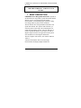
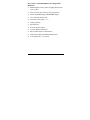
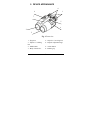
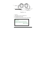
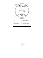
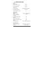
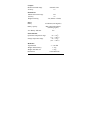
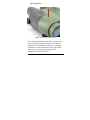
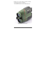
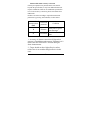
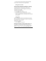
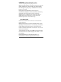
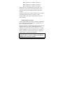
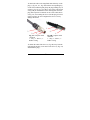
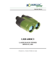
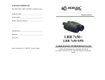
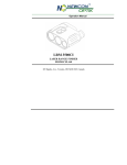
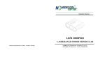
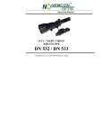
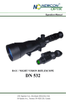
Operation Manual LRB 6000CI LASER RANGE FINDER BINOCULARS 105 Sparks Ave., Toronto, ON M2H 2S5, Canada ii IMPORTANT INFORMATION Read prior to activation You have just purchased a sophisticated electro-optical device that emits invisible laser radiation. To operate it properly, please read this manual carefully. NEVER direct laser beam at the eyes of people or animals NEVER aim the unit at the Sun or bright sources of light NEVER subject the unit to impacts NEVER transport the unit without its case NEVER disassemble the unit. This may be hazardous for you due to high voltage currents in the system ALWAYS keep the unit out of children’s reach ALWAYS remove the battery when the device is not in use for a long period ALWAYS store in a dry place Caution - use of controls or adjustments, or performance of procedures other than those specified herein may result in hazardous radiation exposure iii Caution - use of optical instruments such as binoculars, loupes, mirrors, lenses, etc. with this product increases eye hazard Note: Avoid eye exposure to direct laser beam or its close reflection Prevent bright light from focusing through the eyepieces Never aim the unit at highly reflective objects like mirrors and retroreflective surfaces, which are in close proximity to the laser rangefinder. This can lead to the permanent damage of the photoreceiver incorporated into the device. iv TABLE OF CONTENTS 1. BRIEF DESCRIPTION .......................................... 3 2. DEVICE APPEARANCE....................................... 5 3. DELIVERY SET ..................................................... 8 4. SPECIFICATIONS................................................. 9 5. OPERATION INSTRUCTIONS ......................... 11 Installing the battery ............................................... 11 Using the Device .................................................... 12 Factors affecting measuring distance ..................... 13 Target selection logic ............................................. 14 Operation and service modes ................................. 15 Compass calibration ............................................... 17 Correction of the vertical angle (Elevation correction) .................................................... 18 Hard calibration ...................................................... 19 Soft calibration ....................................................... 22 Distance/Elevation accuracy correction ................. 23 Setting interface format .......................................... 24 Gating mode ........................................................... 24 Data Recall mode ................................................... 25 Computer interconnectivity .................................... 26 GPS interconnectivity ............................................ 28 6. 7. 8. 9. 10. 11. Short mode switching scheme ................................ 28 BEST MEASURING TECHNIQUE.................... 29 STORAGE AND MAINTENANCE ..................... 31 TROUBLESHOOTING ........................................ 32 WARRANTY ......................................................... 33 CUSTOMER SUPPORT..................................... 34 QUALITY CERTIFICATE ................................... 35 2 CAREFULLY READ ALL THE INSTRUCTIONS PRIOR TO USE! FAILURE TO OBEY THE INSTRUCTIONS WILL VOID THE WARRANTY AND MAY CAUSE INJURY! 1. BRIEF DESCRIPTION LRB 6000CI Laser Rangefinder Binoculars (System) is an advanced laser range finder system that enables instant distance, speed, vertical and horizontal angular measurements. An outstanding optics provides a sharp, clear image under any observation conditions. The unit utilises time-of-flight method of distance and speed measurement. The System sends invisible, eye safe laser pulses to the target. The returned pulses are captured by the digital circuitry. The time difference is used to calculate the distance to the target. A built-in digital compass measures an angle between the optical axis and direction to the magnetic North Pole. The unit complies with CFR 21, Part 1040.10 and Part 1040.11. A built-in inclinometer allows elevation angle measurements and height (depth) calculations. 3 Key Features of the LRB 6000CI Laser Rangefinder Binoculars Modern digital circuitry allows targeting through most types of glass First, last or the most reflective target acquisition Meters/Yards/Mils/Degrees/KMH/MPH display Last 10 measurements recall Selectable reticle shape (+ or ) Gating capability Speed detector Accurate digital compass Accurate digital inclinometer RS-232 bidirectional communication GPS interoperability (PLGR/DAGR protocol) Auto shutoff time – 16 seconds 4 2. DEVICE APPEARANCE 4 6 1 7 5 8 3 2 Fig. 1. Front view 1 – Eyepieces 3 – Objective / emitting lens 5 – Mode button 7 – Body of the device 2 – Objective / receiving lens 4 – Dioptric adjustment rings 6 – Action button 8 – Rubber grip 5 1 9 10 11 Fig. 2 Rear view 1 – Eyepiece 9 – Interpupillary distance adjustment lever 10 – Model Identification label 11 – Identification and certification label (on the bottom): 6 6 1 8 7 2 4 3 Fig. 3 Display 1 – Low battery indicator 2 – Reticle (either -¦- or 3 – Units of measurement 4 – Measurement result 5 – Gating indicator 6 – Laser active indicator 7 – Ready mode indicator 8 – Setup mode indicator 7 ) 3. DELIVERY SET Standard delivery set for LRB 6000CI includes: Qty LRB 6000CI Carrying case Neck strap User’s manual Warranty card Cleaning cloth Computer cable CD with communication software Hard case 9V non-magnetic Lithium battery 1 pc. 1 pc. 1 pc. 1 pc. 1 pc. 1 pc. 1 pc. 1 pc. 1 pc. 1 pc. Optional items GPS cable Exact delivery set depends on details of a contract or purchase order. 8 4. SPECIFICATIONS Optics Magnification Objective lens diameter Exit pupil diameter Field of view Type of coating Interpupillary distance Dioptre adjustment range 7x 50 mm 7.1 mm 5 Fully multi-coated optics 58-72 mm ±4 Range Finder Laser Measuring range Accuracy and display resolution First, last and auto target selection Meters / Yards display Class 1, eye safe, 905 nm 1 – 6,500 m 1 m Yes Yes Last 10 measurements recall Reticle Gating capability Yes -¦- or 100 – 3,900 m; 100 m step Speed Detection Measured speed range Accuracy 5-400 km/h or 3-250 mph 2 km/h or mph 9 Compass Measured azimuth range Accuracy 6400 mils /360 ±1 Inclinometer Measured elevation range ±60 Accuracy ±1 Yes (Meters or Yards) Height measuring Power Battery Battery capacity 9V Lithium (non-magnetic) Min 5,000 measurements (Scanning regime) 'Low Battery' indicator Yes Environmental Operational temperature range Storage temperature range Mechanics Tripod thread Weight without battery Weight with hard case Dimensions -25…+50oC (-13…+122oF) -45…+65oC (-49…+149oF) ¼” x 20 TPI 1.3 kg 3.5 kg 210x150x80 mm 10 5. OPERATION INSTRUCTIONS Installing the battery Open the battery compartment using a suitable tool, or a coin. Insert a 9V Lithium non-magnetic battery provided with your device Connect the battery to the battery snap Refit the battery compartment and tighten the screw. If the battery compartment cover does not close tightly and evenly, check that the battery snap wires are neatly packed inside the battery compartment and the cover is aligned over the edge of the battery compartment. Note: Battery in metal casing will diminish compass accuracy. Non-magnetic batteries should be used for the utmost compass performance. LRB 6000CI is equipped with battery monitoring sensor. If display shows “LOW BATTERY” warning when battery voltage falls below 6.5V this indicates that the battery is used up. You can still get readings, but the battery needs to be replaced soon. 11 Using the Device The LRB 6000CI operational procedures are design to allow the user to use most applicable options in the fastest time possible. To activate it, press and hold Action button (6, Fig.1) for one second. At start the unit comes into Ready to Measure mode indicated by the word ‘READY’ on the display visible through the eyepiece. Pressing Action button (6, Fig. 1) again will initiate measurement procedure. The results of measurement are displayed in default form of “Distance (M), Azimuth (mils) and Elevation (mils)” measurement parameters also can be modified to user preference (see Setup Mode). If results of measurement are unreliable four dashes (‘----‘) will be displayed in the area (4, Fig. 3). Pressing Mode button (5, Fig. 1) gives the user the options to change settings from Factory default to specific modes required by user. For full list of Mode options please refer to Operation and Service modes If the target is located below the unit the result of vertical measurement (elevation or height) will be preceded with minus (“-“) sign. 12 Factors affecting measuring distance Though maximum measurement distance depends on target reflectivity, weather conditions and other conditions, for most targets the unit will provide accurate ranging for up to 4,000 meters. Under good conditions a large size target can be measured up to 6,500 meters. Target reflectivity depends on its color, surface finish, size, shape, position in relation to the laser beam, etc. Bright target colors are more reflective than darks. A polished surface is more reflective than a rough one. Larger targets reflect better than small ones. Ranging a target perpendicular to the laser beam provides better results than the one positioned at a sharp angle to the beam. Weather conditions that influence air transparency (rain, fog, snow, mist) reduce maximum range. Bright sunny days will reduce performance as well as IR sun radiation may cover reflected laser impulses. While the unit will measure through many glass types, measuring through glass may reduce accuracy. Natural hand tremor decreases the accuracy of long distance ranging. Using of a tripod is highly recommended. Note: device may produce false readings when reticle is aimed at the sun or in ± 20˚ solid angle from the sun. 13 Target selection logic On its way towards the target the laser beam may be reflected from various objects, thus decreasing ranging accuracy. The smaller, the farther, and the less reflective is the target – the higher is the possibility of obtaining an incorrect measurement. To improve accuracy the unit has a built-in target selection logic that allows user the option of choosing which target to range: the nearest (‘first’), the farthest (‘last’), or the most reflective (‘auto’). This mechanism helps selecting the target when ranging from behind the bushes, wires, through the falling snow, or in similar conditions. Furthermore, it enables ranging a target in front of a bigger object, such as a wire in front of the wall. Note: Even with target selection logic the unit may not always be able to range the desired target as its reflectivity may be too low to produce enough laser beam reflections for statistically reliable calculation. Individual Measurement and Scanning regimes The unit can operate in two methods: (1) Individual Measurement and (2) Scanning. In Individual Measurement method the unit performs single measurement when Action button is pressed shortly, in Scanning regime the unit 14 repeatedly measures and displays results every second while A button is pressed. To activate Scanning regime press and hold Action button in Ready mode. The unit will work in Scanning regime while Action button is pressed. Scanning or Individual Measurement regimes are available for any selected mode of measurement. When two or more parameters are measured in Scanning regime though first result will be displayed, the second and other results will be shown at the display if Action button is released. Nevertheless all data is transferred to the PC and recorded in internal memory, and may be recalled (see Data Recall mode for details.) Operation and service modes Pressing Mode button (5, Fig.1) in Ready mode switches the unit between modes of operation, to activate any desired mode from the menu you must confirm your selection by pressing Action button (6, Fig.1). The unit has the following modes of operation: Ready – Unit is ready to perform measurements dFLt – sets default mode of operation with factory settings, GAtE – allows to set gating distance for measurement 15 Std – allows the user to select single action measurements: o Distance only (d) o Compass Only (C) o Elevation Only (E) o Speed Only (S) o Height Only (H) o Speed + Distance (Sd) o Distance +Compass + Elevation (dCE) Unit – allows the user to select units of desired measurements, o Distance from M to Y o Compass & Elevation from Mils to Degrees o Speed from KMH to MPH* * this option is only available if Std Speed is selected rEc – allows data recall of the last 10 measurement results, o CLr – Clears all Measurement SEt – allows the user to select the following advanced options: o FrSt – First Target Measurement o LASt – Last Target Measurement 16 AUtO – Last Target Measurement* PLGr – Communication to PLGR GPS* PC – Communication to PC* Reticule – Change reticule from + (cross) to (rectangle) o CAL – Compass calibration ▪ CALc – compass calibration (CI model only) ▪ Corr – accuracy correction of active parameters ▪ Display and firmware version check *not shown in the menu if currently selected o o o o Compass calibration Full calibration process consists of three procedures, which shall be conducted in the following sequence: 1. Elevation correction 2. Hard calibration 3. Soft Calibration However all three procedures shall be done only at initial installation and integration of the device, or if some large hardware elements permanently attached to the device were changed. For example bracket made of 17 magnetic metal was replaced or modified. If calibration is performed only to improve accuracy of readings, only the Elevation correction and Soft calibration shall be performed. Correction of the vertical angle (Elevation correction) - Turn on the LRF. - In the LRF menu, select «Std», then «E». Press ACTION. - Select «SET», then «CAL». Press ACTION. - Position LRF strictly flat. Select «corr» and press ACTION. If device is not positioned perfectly level during calibration, this process will introduce permanent error for all future measurements; this error will equal the error of installation during the correction procedure. 18 Hard calibration Fig. 4 Axis of horizontal rotation Note: during all calibration procedures, always put as far as possible all magnetic/metal parts and devices that generate electromagnetic interference (example – Cellphone) from the measurement area, unless these parts or devices will be permanently used in conjunction with the LRF device. 19 - Turn on the LRF. - In the LRF menu select «SET», then «CAL». Press ACTION. - When the text «CALc» is shown, set the LRF horizontally on a flat surface, where the LRF will be rotated around vertical axis. Note: to achieve as accurate calibration results as possible, the digital compass should be exactly on the axis of rotation, please refer to the Fig 4 showing the location of the axis of rotation for this procedure. - Press the ACTION. - -- Start rotating the LRF module to perform one or two full rotations duration 1 min. The display will be blinking «CAL» during entire process. - When the display switches to «CALc», change LRF position to be on the left side down. Note: to achieve as accurate calibration results as possible, the digital compass should be exactly on the axis of rotation, please refer to the Fig 5 showing the location of the axis of rotation for this procedure. - Press ACTION. - Start rotating the LRF module to perform on or two full rotations duration 1 min. The display will be 20 blinking «CAL». When display switches to «CALS», it means that calibration is finished. - Press MODE button to exit the calibration mode. Fig. 5 Axis of on-side rotation 21 Soft calibration Prior to conducting the procedure determine accurate direction to North, West, South and East, accuracy of these references will define accuracy of the compass calibration. - Turn on the LRF. - In the LRF menu select «SET», then «CAL». Press ACTION. - Then select «CALS» and press ACTION - When the display shows «C 0°», the LRF shall be set horizontally and aim the LRF to the North (0 degrees), press ACTION. - When the display shows «C 90°», the LRF shall be set horizontally and aim the LRF to the East (90 degrees), press ACTION. - When the display shows «C 180°», the LRF shall be set horizontally and aim the LRF to the South (180 degrees), press ACTION. - When the display shows «C 270°», the LRF shall be set horizontally and aim the LRF to the West (270 degrees), press ACTION. - When the display shows «corr» press MODE to exit the calibration mode. 22 Distance/Elevation accuracy correction If the System produces any measurement errors that lie beyond unit specification, it may be an indication that unit requires calibration similar to one conducted at production level. To do accuracy correction, please select Corr from CAL menu. Perform correction according to required measurement parameters by pressing Action button, see table below: Active mode of measurement (Std) d E Correction parameter Condition Install unit at 1 meter1 from flat target2 Put unit in a level Elevation plane Distance 1 – Accuracy of distance correction will depend on accuracy of installation against target. If distance is 0.9 meters, then unit will have 0.1 m offset during all future measurements. 2 – Target should not have high-reflective surface (white color is not considered high reflective in this case). 23 3 – If device detects measurement result more than 0.0° elevation correction was not performed. Setting interface format In this mode data communication standard is set. The unit can output measurement data via RS-232 port in either PC format (description of the proprietary format can be obtained from Newcon upon a request) or in the format accepted by PLGF/DAGR. To select required data format: Select PLGr or PC from SEt menu Pressing Action button will activate PC or PLGR format, the display name of format that can be activated will be shown. Gating mode In this mode gating function is activated: here user can set the minimal distance to the target, any object closer than the gating distance will be ignored. To select Gating Mode: Select GAtE from main menu Minimal gating distance of 0 meters (display: 000 m) will be initially set, further pressing M button will increase gating distance by 100 m up to 3,900 m. When the desired distance is reached – select it by pressing Action button. 24 OVER 100M – indicates that gating is active To deactivate gating choose gating value zero. Note: The gating distance can only be increased. To exit the gating selection cycle without setting any gating distance click through full gating range with M button or hold M button for 2 seconds. Gating feature helps measuring remote targets in unfavourable atmospheric and environmental conditions by eliminating reflections from snowflakes, raindrops, industrial wires, tree branches, etc. At the same time, if gating distance is set incorrectly, you can remove the desirable object from measurement range. Data Recall mode In Data Recall mode results of the last 10 measurements can be displayed. Measurement results are saved in on-board memory in sets depending on the parameters set for measuring, for instance, if only distance is measured - the set will consist of one number, if distance and azimuth are measured – the set will consist of two numbers. To enter Data Recall mode select rEc from the main menu. First measurement set number (display name: rEc 1) will start flashing. Pressing M button moves the unit along the list of measurement set numbers and measurement results: 25 rEc 1, distance 1, azimuth 1, elevation 1, rEc 2, distance 2, azimuth 2, elevation 1, …, rEc 0, distance 0, azimuth 0, elevation 0. Measurement sets are numbered in reverse order: first recalled set is the result of the last measurement. If any parameter has not been actually measured it will not be recalled. Pressing A button at any moment within the list of recalled results brings the unit to Ready to Measure mode. Choosing cLr at the end of recalled data will erase the device memory. Computer interconnectivity The unit supports RS-232 interface. The data is transmitted as hex string code with fixed baud rate of 38400 bit/sec, 8 bits, one stop bit, and no parity. Physical connection is performed through circular connector designed for the heavy-duty outdoor applications, the connector is located on the bottom of the device. Currently Newcon supplies two types of connectors, one with quick release connector or screw-locking connector. Operation with both types is described in the manual. Do not apply excessive force when disconnecting cable. Damage to cable or connector resulting from improper handling is not covered by warranty. 26 To attach the cable to the rangefinder match the key on the plug (1, Fig. 6A, or 1, Fig. 6B) with the corresponding key on the socket and then push gently the plug holding it by its casing (3, Fig. 6A or 3, Fig. 6B), in case of the cable shown on Fig. 6B you should hear a click meaning that connector plug and receptacle are latched. In case of the cable shown on Fig. 6A, start rotating the sleeve until the plug is locked in the receptacle, do not overtighten the sleeve as it may damage the thread. 3 3 2 2 1 1 Fig. 6B. Computer cable connector 1 – Key; 2 – Sleeve; 3 Rubber casing Fig. 6A. Computer cable connector 1 – Key; 2 – Sleeve; 3 Rubber casing To detach the cable slide sleeve (2, Fig. 6B) away from the unit and pull the plug out or unscrew the sleeve (2, Fig. 6A) and detach the plug. 27 GPS interconnectivity LRB 6000CI can transmit the acquired data to a GPS receiver using DB15 connector and PLGR/DAGR protocol. An optional cable is required. To work with GPS, perform the following steps: Choose dFLt measuring mode; Switch the rangefinder to PLGr mode; Connect the rangefinder and GPS unit with the cable. For each measurement GPS will display the absolute coordinates of your target. Note: If the rangefinder is not set initially to dFLt mode, the GPS will not operate properly. Note: GPS unit automatically adjusts coordinates to reflect actual magnetic declination. Therefore, coordinates displayed on the GPS may differ from those calculated by the computer. Short mode switching scheme Upon request, your LRB 6000CI rangefinder may be manufactured with reduced functionality. This version is easier to use, and it is beneficial for users planning to work with GPS only. The short mode switching scheme does not transmit data in PC software format. Note: The rangefinder can be programmed for the short or full mode switching scheme at the factory only. 28 6. BEST MEASURING TECHNIQUE Laser range finder measures distance by catching laser beam reflected from the target. Everything that improves reflection increases the measurement reliability and maximum range. 1. Use tripod when ranging remote targets. The longer is the distance, the greater is the beam shift due to hand tremor. 2. Aim at a surface on the target that is the closest to perpendicular to the laser beam. The closer you get – the stronger will be the reflection. 3. The unit deploys sophisticated software that tries to understand which target you are aiming at. However, due to beam divergence several objects may produce a strong reflection. To help the System recognise the target the Target Selection Logic may be used. For example, if ranging a wire in front of a building, selecting the “first” target will produce a more reliable result. Alternatively, when aiming at a chimney behind the trees, selecting “last” target will be better. By default the System assumes “auto” target selection, that is, the object producing the most reflections will be considered a target. 4. Another way to improve reliability of measurement is to use gating mechanism. If gating is active reflections from all objects closer than the gating distance will be ignored. This is especially effective when ranging in 29 unfavourable atmospheric conditions, that is, in the rain, fog, haze or in the bright sun. Gating provides better results than the “last” target selection, but it requires preliminary rough distance estimation to cut off all objects closer than the chosen one. Note: Gating setting is remembered by the System until altered. Therefore, if you forget to turn the gating off, the next time you start measuring it can ignore the desired object, if it is closer than the gating distance. The unit will display four dashes instead of the measurement results. “Over 100 meters” display indicator shows active gating. 30 7. STORAGE AND MAINTENANCE The unit is a sophisticated precision optical instrument equipped with laser and electronics. Therefore, it should be handled with due care. Keep away from direct sunlight. Avoid impacts, jolts, dust, moisture, and sharp changes of temperature. Do not use the device at temperatures higher than 50oC (122oF). Do not touch optical surfaces. Doing so may damage the anti-reflection coating. Clean optical surfaces only with professional camera lens cleaning supplies. Clean the exterior of the unit with a soft clean cloth. Keep the unit away from heating appliances and central heating. Remove the battery when storing the device for long time. All repair works must be performed by an authorized service. 31 8. TROUBLESHOOTING Ranging does not work. The display is transparent. Check the charge of the battery. Replace it if it is weak. Ranging does not work. The display indicates results of the last measurement. Wait for 8 seconds until the display becomes transparent, and press the Action button again. Black dots are visible on LCD. Liquid Crystal Display may have small black dots, scratches and other blemishes inherited from the manufacturing process. These flaws are strictly regulated by number, area and location and do not degrade the product's measurement capabilities. Range measurement cannot be obtained. Make sure that neither your hand nor finger is blocking objective lens, laser emitting lens or receiver lens. Hold the unit firmly (avoid hand tremor) while pressing the Action button. Check that the target is within measuring range of the device and the gating mode does not cut it off. 32 9. WARRANTY NEWCON warrants this product against defects in material and workmanship for one year from the date of the original purchase. Longer warranty is available, subject to the terms of the specific sales contract. Should your Newcon product prove to be defective during this period, please deliver the product securely packaged in its original container or an equivalent, along with the proof of the original purchase date to your Newcon Dealer. Newcon will repair (or at its option replace with the same or comparable model), the product or part thereof, which, on inspection by Newcon, is found to be defective in materials or workmanship. What This Warranty Does Not Cover: NEWCON is not responsible for warranty service should the product fail as a result of improper maintenance, misuse, abuse, improper installation, neglect, damage caused by disasters such as fire, flooding, lightning, improper power supply, or service other than by a NEWCON Authorized Service. Postage, insurance, and shipping costs incurred while presenting your NEWCON product for warranty service are your responsibility. If shipping from North America please include a cheque or money order payable to NEWCON OPTIK for the amount of US$15.00 to cover handling and return shipping. 33 10. CUSTOMER SUPPORT Should you experience any difficulties with your NEWCON OPTIK product, consult the enclosed manual. If the problem remains unresolved, contact our customer support department at (416) 663-6963 or toll free at 1-877-3686666. Our operating hours are 9am-5pm, Monday - Friday, Eastern Standard Time. At no time should equipment be sent back to Newcon without following the instructions of our technical support department. NEWCON OPTIK accepts no responsibility for unauthorized returns. To locate NEWCON Authorized Dealer call: Tel: (416) 663-6963 Fax: (416) 663-9065 Email: [email protected] Web: www.newcon-optik.com The defective products should be shipped to: From all countries: 105 Sparks Ave., Toronto, ON M2H 2S5, CANADA 34 11. QUALITY CERTIFICATE Serial number _____________________________ The unit indicated above has passed the quality inspection. Production date Quality Inspector Purchase date 35 R1 – 2.11 NEWCON OPTIK Printed in Canada