1
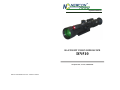
Operation Manual
DAY/NIGHT VISION RIFLESCOPE
DN510
105 Sparks Ave., Toronto, ON M2H 2S5
Newcon International ltd. © 2010 Printed in Canada
IMPORTANT INFORMATION
Read prior to activation
You have just purchased a complicated electronic device. To operate it
properly, please read this manual carefully. Here are some common
precautions that must be noted.
• NEVER disassemble the unit. This device contains high voltage,
which may be hazardous to your health!
• NEVER aim active unit at intense light sources (i.e. lights,
headlamps, campfires, the moon, etc.)
15. QUALITY CERTIFICATE
The DN 510 is suited for usage.
Production date ____________________________
Serial number _____________________________
Quality control ____________________________
Purchase date _____________________________
Salesman _________________________________
• NEVER reverse the polarity of a battery
• NEVER connect the unit to external power sources
• ALWAYS remove batteries when not in use for a long period
Quality inspector ____________________
(Signature)
• ALWAYS keep the objective lenses covered when not in use
• ALWAYS store in a warm dry place when not in use
FEATURES OF A DN 510 NIGHT-VISION SCOPE
All known models of day/night scopes with removable eyepieces use
standard optic scheme of a day-vision scope with 11-13 lenses. As a rule,
light ratio of such system at low sight magnification is defined not by an
objective lens diameter, but by a light ratio of an erecting system (4
lenses). The actual F-number of all system does not exceed 3.0, which is
clearly not enough for night-vision equipment. In addition, usual daytime
scopes have relatively small eyeshot angles. Due to that reason in a night
scope only centre of the electronic tube working area is used.
2
19
13. WARRANTY
NEWCON OPTIK warrants this product against defects in material and
workmanship for one year from the date of the original date of consumer's
purchase, but no more than 18 months from the date of manufacturing.
Should your Newcon product prove defective during this period, please
bring the product securely packaged in its original container or an
equivalent, along with proof of the date of original purchase, to your
Newcon Dealer. Newcon will, replace or repair (or at its option replace),
the product or part thereof, which, on inspection by Newcon, is found to
be defective in materials or workmanship.
What This Warranty Does Not Cover:
NEWCON is not responsible for warranty service should the product fail
to be properly maintained or fail to function properly as a result of misuse,
abuse, improper installation, neglect, damage caused by disasters such as
fire, flood, lightning, improper electrical current, or service other than by
a NEWCON Authorized Service. Postage, insurance, or shipping costs
incurred in presenting your NEWCON product for warranty service are
your responsibility. Please include a check or money order made out to
NEWCON OPTIK for the amount of $10.00 to cover shipping and
handling.
14.CUSTOMER SUPPORT
Should you experience any difficulties with your Newcon OPTIK
product, consult the enclosed manual. If the problem remains unresolved,
contact our customer support department at (416) 663-6963 or Toll free at
1-877-368-6666. Our operating hours are 9am-5pm, Monday - Friday,
standard East time. At no time should equipment be sent back to Newcon
without following the instructions of our technical support department.
Newcon accepts no responsibility for unauthorized returns.
To locate the NEWCON Authorized Dealer call:
Tel: (416) 663-6963 Fax: (416) 663-9065
Email: [email protected]
Website: www.newcon-optik.com
The defective products should be shipped to:
In USA: 2331 Superior Ave. Cleveland, OH 44114
In Canada: 105 Sparks Ave., Toronto, ON M2H 2S5 Canada
18
The DN 510 uses a specially designed unique optical scheme (23
lenses) that provides a 2-2.5 stronger light ratio, twice wider field
of view and complete resolution capability using the whole
working area of the electronic tube.
All this in combination with a powerful generation II or III image
intensifier tube provides comfort and perfect visibility both at daytime and night-time under conditions of low light, when other
day/night scopes do not work any more.
CONTENTS
1.
2.
3.
4.
5.
6.
7.
8.
9.
10.
11.
12.
13.
14.
15.
Brief description
External appearance of the device
Technical characteristics
Supplied accessories
Using the device at day-time
Using the device at night-time
Battery installation
Installing on a hunting rifle
Adjusting the scope
Taking photos and video shooting
Storage and maintenance instructions
Trouble shooting
Warranty
Customer support
Quality certificate
BEFORE USE CAREFULLY READ THE STORAGE,
MAINTENANCE AND INSTALLATION INSTRUCTIONS!
FAILURE TO OBEY THE INSTRUCTIONS
WILL VOID THE WARRANTY.
3
1. BRIEF DESCRIPTION
12. TROUBLE SHOOTING
Your DN 510 device is a universal hunting scope, intended for
observation and hunting both at daytime and night time.
The scope does not work.
Check that the battery is installed properly.
Check the charge of the battery.
Replace if it is weak.
Do not use old battery with a new one.
The device is universal due to removable eyepiece.
Day
The day-time part employs a specially designed powerful optic scheme
(23 lenses) with day eyepiece, providing 3.0 to 6.0 times magnification,
F-number of the system reaches 2.0 (at 3.0x magnification) and visual
angle from 12 to 5.2 degree.
Night
The nighttime scope employs 2nd or 3rd generation image intensifier tube
(18mm, MCP), working on a principle of amplifying of available light in
the visible and close infrared range. Together with the high-light-ratio
day-time channel the device provides night-time range of 400-800м,
system magnification 3.7 to 7.3 times and visual angle 12 to 5.2 degree.
The image does not appear in focus.
Bring the inspected object to the center of the image. Turning the
objective lens ring (10), and/or the eyepiece (2, 8) adjust to achieve the
clearest image on the screen. Repeat the steps of focusing if necessary.
If the view still does not seem in focus, clean the lenses, they could be
foggy or dusty.
Reticle is not in focus (Parallax phenomenon).
It occurs in optical sights when observing the objects on a distance
different from one the objective lens is set on. It appears as a
displacement of the reticle from the initial aiming point due to the
shooter’s eye’s displacement from the aiming axis. To eliminate the
parallax objectives lenses of optic sights are designed such that they may
be refocused for a shooting distance. Parallax does not happen in nightvision scope.
No picture in the nighttime channel.
When bright light gets into the objective lens of the night vision device it
may result in disappearing of the image as the automatic shut-off feature
comes into action to protect the device. Whenever this happens, turn the
switch to the OFF position. In a minute or two the device will be ready for
further operation.
If the image has been lost at the moment of a shot, check contacts in the
battery compartment.
Black dots on the Nighttime channel screen
These are the cosmetic blemishes in the image intensifier, which do not
affect the performance, or reliability of a night vision device and some
number of varying sizes are inherent in the manufacturing process. Most
of them are seen only at daytime and become almost invisible during the
operation.
4
17
The TTL system, which is installed at most SLR cameras easily estimates
exposure during the shooting with the device. If your camera is not
equipped with the TTL system, the table can approximately estimate the
shutter speed at the diaphragm number of the camera equal 2.0:
2. EXTERNAL APPEARANCE OF THE DEVICE
1
3
2
7
1
----------------------------------------------------------------------------------ISO,
50 100 200 400 800 1600 3200
----------------------------------------------------------------------------------Sh.speed, sec. 2
1
1/2 1/4
1/8 1/15 1/30
-----------------------------------------------------------------------------------
NOTES.
Use an ISO 400 film or higher.
Using of a tripod is strongly recommended to achieve
higher quality photos.
11. STORAGE AND MAINTENANCE INSTRUCTIONS.
Warning!
After transportation or keeping the device at temperature lower than -40°c
(-40°f), the device must be warmed up to ambient temperature, from -10°c
(14°f) to +40°c (104°f), relative humidity of 80% max. At 20°c (68°f).
DN 510 is a sophisticated precision optical instrument equipped with
electronics. Therefore, it should be handled with due care.
• Keep your device away from direct sunlight, impacts, dust,
moisture, and sudden changes of temperatures.
• Do not touch the optical surfaces with fingers. Doing so may
damage the anti-reflection coating.
• Cleaning of optical surfaces is possible only with professional
camera lens cleaning supplies.
• To clean the exterior of the device, use a soft clean cloth.
• Do not take the cover off the lens if not necessary.
• Keep away from heating appliances and central heating.
• Make sure to switch off the unit during periods of non-operation
and when storing the device for long period of time.
• Do not apply superfluous efforts at work with lens assembly, agile
elements and thread connections.
16
4
10
5
6
9
8
1 – Infrared illuminator; 2 – Night eyepiece; 3 – Bayonet button; 4 – Flip-open
cover; 5 – Aiming mark adjustment; 6 – Mount; 7 – Magnification ring;
8 – Daytime eyepiece; 9 – Rubber eyepiece guard; 10 – Objective lens ring.
3. TECHNICAL CHARACTERISTICS
Day
General
Magnification, x
Field of view, degree
Objective lens
Focus length, mm
F-number (for 3.0x magn.)
Focus range
Eyepiece
Focus length, mm
Eye relief distance, mm
Diopter setting
Mechanical characteristics
Overall length, mm
Weight, kg
Working conditions
Temperature range
Relative humidity
Night
3.0-6.0
3.7-7.3
12 to 5.2
100
2.0
10 m to infinity
33
27
45
+2, -4
225
0.97
226
1.10
-40 oC to +50 oC
0 to 98%
5
10.TAKING PHOTOS AND VIDEO SHOOTING
Electrical parameters (Nighttime channel)
Power supply
1 lithium battery of
SRI123А type
3
30
3V (2 AA batteries)
Voltage, V
Continuous work time, h, minimum
I/R illuminator
Image intensifier tube
Photocathode sensitivity, μA/lm
Mode DN-510-A Gen. II
Mode DN-510-B Gen. II
Mode DN-510-C Gen. II
mode DN-510-D Gen. III
Gain
Resolution, pl/mm
240
450
600
1,800
20,000-30,000
30-55
Infrared illuminator (optional)
Power, mW
Illumination angle, degree
Illumination Spectrum, nm
P.S.
75 or 200
8-10
805
Technical characteristics may be improved without prior notice.
4. ACCESSORIES
DN510 is supplied in the following assembly:
- Device
- Daytime eyepiece
- Nighttimes eyepiece
- Rubber eyepiece guard
- Objective cover
- Rifle mount
- User’s manual
- Warranty card
- Case
Optional accessories:
- Infrared illuminator –75 or 200 mW
- Camera/video adapter (52mm/37mm)
6
1 pc.
1 pc.
1 pc.
2 pc.
1 pc.
1 pc.
1 pc.
1 pc.
2 pc.
1 pc.
1 pc./each
DN 510 can be supplied with an optional adapter for photo/video
devices for night photo/video shooting.
Night photo shooting with DN 510 is easily performed using 35mm SLR
cameras such as Nikon, Canon, and Pentax etc. with standard objective
lens (50-58 mm focus).
VIDEO
Preparation of the device for photo shooting:
1. Screw the adapter ring supplied in the set (diameter 52mm or 37mm)
into the setting place of the light filter of the objective lens in your
camera. (If the objective lens of your camera has another setting
diameter for a light filter (for example, 49mm or 58mm) your have to
purchase step up or step down adapter rings from the 52 mm to your
size). Such adapters are typically sold at camera stores.
2. Remove the rubber eyepiece guard from the scope.
3. Set the eyepiece in the medium position.
4. Screw the adapter ring with the camera in an internal groove of an
eyepiece.
5. Switch on the device and focus the assembled system with the help of
the objectives of the device and camera. If the image cannot be focused
the camera with the ring should be removed and the coupling of the
eyepiece of the device should be rotated a little. Assemble the system
again and check its focusing. At some position of the eyepiece and
objective of the camera the system will be focused exactly;
6. Fasten the adapter ring with the camera to the body of the eyepiece of
the device with the help of three locking screws. During further photo
shooting sharpness of the system is obtained with the help of the
objective of the DN-510 only;
7. Set diaphragm on the objective of the camera equal 2.8 or 4 (shooting is
possible even at lower diaphragm indices, for example 2, but the
obtained pictures will have worse resolution). Taking photos with a
completely opened diaphragm of the objective is justified for the
shooting of quickly moving objects only.
15
4. Direct the rifle to the point of aiming by mechanical sight (bead
with a slot) (if it is possible). At this stage it is suitable to apply
laser of cold test shooting (LCTS) inserted in the barrel of the
rifle, which indicates geometrical point of the barrel position
(sold separately).
5. Unscrew the protective caps of
Up
the bias screws of the aimed
Down
graticule. Turning the bias
Right
screws of the reticle obtain the
matching of reticle crosshairs
with the aimed point, set by the
Left
mechanical sight or LCTS;
6. Remove the rifle from scoped
machine and take out LCTS;
7. Make 2-3 shots. Having examined the target make necessary
corrections (for example, in order to move the hit point
downwards and leftwards, screws of the mechanism should be
turned counter clockwise, in the directions Down and Left
correspondingly. The aiming point is moving upwards and
rightwards);
8. Make a control shot and find out whether the aiming point
coincides with the bullet hit point. (Make the correction again
if necessary);
9. Set the protective caps into their places.
The device is ready for operation.
The marking displacement mechanism is equipped with a
click holder that displaces the marking both in vertical and
horizontal direction. One click equals 12.5 mm shift of the
marking at the distance of 100 m (0.45” at 100 yards). Newer
versions have 1/4 MoA (minute of Angle) adjustments.
14
5. USING THE DEVICE AT DAY-TIME
During the bright time of the day:
1. Install daytime eyepiece on the device. In order to do this,
match white dots at the device and daytime eyepiece. Insert the
eyepiece into the bayonet on the device, PRESS device and
eyepiece together and turn clockwise till the red dot on the
device matches the dot on the eyepiece (approximately 10
degrees).
2. Take the objective cover off.
3. Rotate the eyepiece till you get the reticle in focus.
In order to eliminate parallax with the help of the focusing ring of
the objective lens set approximate observation range (observation
range in metres is indicated).
Focusing ring
4. With the help of magnification ring set the desired device
magnification.
Device is ready for observation.
RECOMMENDATION.
It is advisable to perform device adjustment at maximum
magnification.
7
6. USING THE DEVICE AT NIGHTTIME
Must be done only during the dark time of the day:
1. Take off the daytime eyepiece. In order to do this press the bayonet
button, turn the eyepiece counter-clockwise. Pull the eyepiece out,
some effort might be required, since a vacuum is created because of
water-resistant design.
2. Install nighttime eyepiece in the same manner, in which daytime
eyepiece is installed.
3. Install the battery as it is indicated by the rules (see battery installation
paragraph).
4. Take off the objective cover.
5. Turn on the device – switch position ON. 1-10 seconds later greenish
fluorescence will appear on the screen (passive mode).
6. Rotate the eyepiece till you get the reticle in focus.
7. Turn the focusing ring till you get the maximum definition of the
picture.
8. With the help of magnification ring set the desired device
magnification.
9. If you need to illuminate the observed object, install and switch on the
infrared illuminator (active mode).
10. After the end of work turn the switch to OFF position.
11.After you finish working with the device, close the objective with the
cover.
Do not forget to switch the device off after end of WORK!
Warning!
Do not use nighttime channel at daytime.
Do not aim working nighttime device at bright objects: bright lamps, the
Sun, welding, etc. – that may cause decrease of the device brightness
amplification coefficient.
In order to eliminate the phenomenon of photocathode fatigue do not
leave night-time device switched on in the same position for more than 30
minutes at the time when the light is bright (in the morning, at day-time
and in the evening).
8
• Insert the grippers (6) and gripper screws (7) into the bushings
(4, 5). For stiff fixation tighten the screws (6, 7). In case of
need the excessive front part of the mount (3) may be removed.
Installation is completed and the device is ready for use as a
hunting scope.
ATTENTION! In case you use other type of binding, to
eliminate the phenomenon of shooting point displacement,
device binding should be advised with Newcon Optik,
because usually such displacement is caused by unqualified
installation.
9. ADJUSTING OF THE SCOPE
Before the adjustment of the sight its objective should be adjusted
for a distant object (select infinity) in daytime or a dark time with
the opened cover of the objective.
The adjustment of the sight should be performed only for the
daytime scope. The change of the eyepiece does not affect the
sight adjustment.
The sight should be adjusted using the adjusting target or a remote
point.
Adjustment of the sight is performed in the following way:
1. Fix the scope on the rifle.
2. Set a panel with a target or select the point of aiming.
3. Set the rifle on the scoped machine.
13
Installation of the device should be performed according to the
following rules:
• Check the prominence of fixation screw (2) that bind the rail (3) to the
body of the device over the top surface of the mount. The prominence
must not be less than 2.5 mm or more than 3.0 mm. This is especially
important if in the body of the device there is a dead threaded hole.
For the reach-through holes the prominence may reach 3.5 mm, but
must not be less than 2.5 mm. In order to meet this requirement you
can cut the threaded part of the screws at length;
• Prepare the glue according to an instruction (the glue need to be of a
certain strength not less than 200 kg/cm2, for example epoxy) and
apply it to (A) surface of the mount. The surface of the screws must
remain free of the glue. This is especially important for possibility to
repair the device or to remove the binding mount for installation on a
different rifles;
• Apply hermetic (silicone type) to the threading of the screws (2);
• Fix the mount to the body of the device with the help of the screws
(2), cut to meet the needed length;
• Remove excessive glue (that is pushed out in the points the mount is
connected to the body of the device) with the help of dry cloth and
alcohol-moistened cotton wool, and let the glue take according to its
instruction (for example, 24 hours for epoxy);
• Locate the device on the rail of the rifle so that your eye will meet the
edge of the eyeshade of the device or will be 2-5 cm apart for big
calibres (like .375 H&H Magi). The position of the device must be
comfortable enough so that you would not have to reach forward for
convenient observation;
• Insert the bushing (4, 5) into the bar (3) holes. The bushing (4)
is inserted with the (В) cog pointing downward into the closest
groove on the rail of the rifle. If there is no such groove, then
the bushing (4) is inserted with the (В) cog pointing upwards. It
is recommended that the bushings will be installed at the
maximum possible distance from each other;
12
7. BATTERY INSTALLATION
Night channel of DN510 device needs one
SRI123A Lithium type battery. Make sure
that it is in good condition and polarity is
installed as it is indicated on the body of
battery compartment (plus inside the device).
In order to change the battery open the cover
of battery compartment and install the new
battery, observing polarity.
When using the optional I/R illuminator, you need to install 2 AA
batteries in the illuminator. Follow similar procedure.
8. INSTALLING ON A HUNTING RIFLE
Night-vision device DN 510 may be used as daytime or nighttime hunting
scope.
RECOMMENDATION.
The usage of day and/or night vision riflescopes for hunting may be
limited or illegal in your area.
Please, check with local authorities prior to usage.
Device may be used with various mounts:
1. Standard prism – SP130-DN-510.
2. Weaver 7/8’’ rail - WP135-DN-510.
That facilitates reliable fixation of the device to a particular rifle.
For convenient installation the device is supplied without stiff fixation of
the binding to the device, and in most cases that enables to perform the
device installation to a specific rifle model.
For installation you should contact a specialised armourer workshop
(gunsmith) or – if you are qualified enough – perform the installation
yourself.
9
•
INSTALLATION RULES
Variant I – Adapter rail with Standard prism type (*) –
SP130-DN-510.
Device is fixed with the help of the following parts:
1
•
•
•
2
5
A
4
3
1 – Device body.
2 – Front cradle for Standard prism.
3 – Rear feet for Standard prism.
4 – Mount of the Standard prism type.
5 – Fixing screws.
(*) – According to Ernst Apel GmbH (Germany) catalogue
Front and rear feet (2, 3) are the standard feet with Standard prism (4),
manufactured by the companies that produce the mounts (for example,
Ernst Apel Gmbh (Germany)). The mount of Standard prism type (4) and
screws (5) are optional.
Installation of the device should be performed according to the following
rules:
• Check the prominence of fixation screw (5) that bind the prism (4) to
the body (1) of the device over the top surface of the prism. The
prominence must not be less than 2.5 mm or more than 3.0 mm. This is
especially important if in the body of the device there is a dead
threaded hole. For the reach-through holes the prominence may reach
3.5 mm, but must not be less than 2.5 mm. In order to meet this
requirement you can cut the threaded part of the screws at length;
•
•
•
Install the feet onto the rail (4). Insert the feet (2, 3) in the rifle.
Sliding the rail in the feet, find the position, in which your eye will
meet the edge of the eyeshade of the device or will be 2-5 cm apart for
big calibres (like .375 H&H Mag). The position of the device must be
comfortable enough so that you would not have to reach forward for
convenient observation;
Cut the excessive part of the rail (4);
Keeping the chosen position of the device, fix the feet (2, 3) to the rail
(4) according on the instruction of the feet producer;
Prepare the glue according to an instruction (the glue need to be of a
certain strength not less than 200 kg/cm2, for example epoxy) and
apply it to (A) surface of the rail. The surface of the screws must
remain free of the glue. This is especially important for possibility to
repair the device or to remove the binding rail for installation on a
different rifles;
Apply hermetic (silicone type) to the threading of the screws (5).
fix the bar to the body of the device with the help of the screws (5), cut
to meet the needed length;
Remove excessive glue (that is pushed out in the points the rail is
connected to the body of the device) with the help of dry cloth and
alcohol-moistened cotton wool, and let the glue take according to its
instruction (for example, 24 hours for epoxy).
Installation is completed and the device is ready for use as a hunting scope.
Variant II – Adapter rail with 7/8’’Weaver rail. - WP135-DN-510 type.
Device is fixed with the help of the following parts:
1
1 – Body of the device
3 – Adapter rail 7/8’’Weaver
rail, including:
2 – Fixation screws;
4 – Arresting bushing;
5 – Bushing; 6 – Grip;
7 – Grip screw. (All binding
details are optional).
4 B
10
6 7
2 A 3
5
11