1
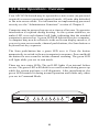
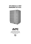
Thank You!
Thank you for selecting the APC KVM Switch. The APC KVM Switch has been
designed for many years of reliable, maintenence free service. APC is dedicated
to the development of high-performance electrical power conversion and control
products and we hope that you will find this product a valuable, convenient addition to your computing system.
Please read this manual! It provides important safety, installation and operating
instructions that will help you get the most from your switch.
Save this manual! It includes instructions for obtaining factory service should
the proper operation of the APC KVM Switch come into question.
Radio Frequency Interference
WARNING: Changes or modifications to this unit not expressly approved by the
party responsible for compliance could void the user’s authority to operate this
equipment.
FCC Statement
NOTE: This equipment has been tested and found to comply with the limits for a
Class A digital device, pursuant to Part 15 of the FCC Rules. These limits are
designed to provide reasonable protection against harmful interference when the
equipment is operated in a commercial environment. This equipment generates,
uses and can radiate radio frequency energy and, if not installed and used in accordance with the instruction manual, may cause harmful interference to radio
communications. Operation of this equipment in a residential area is likely to
cause harmful interference in which case the user will be required to correct the
interference at his own expense.
Canadian Department of Communications Statement
This digital apparatus does not exceed the Class A limits for radio noise emissions
from digital apparatus set out in the Radio Interference Regulations of the Canadian
Department of Communications.
Le présent appareil numérique n’émet pas de bruits radioélectriques dépassant
les limites applicables aux appareils numériques de la classe A prescrites dans le
Règlement sur le brouillage radioélectrique édicté par le Ministère des Communications du Canada .
Table of Contents
Chapter 1 - Product Overview
Feature Overview .......................................................................................................... 1
Compatibility .................................................................................................................... 3
Chapter 2 - Installation
Basic Installation ............................................................................................................. 4
Rack Mount Installation .............................................................................................. 6
Advanced Installation .................................................................................................. 7
Chapter 3 - Basic Operations
Overview ........................................................................................................................... 8
Keyboard Control .......................................................................................................... 9
Keyboard Switching ..................................................................................................... 10
System Control & Maintenance .............................................................................. 11
Chapter 4 - OSD Operations
Activating OSD ............................................................................................................... 12
The OSD Window ......................................................................................................... 13
The Command Menu .................................................................................................. 14
Basic Channel Maintenance .................................................................................... 15
The ID Window .............................................................................................................. 17
Administrator Functions ............................................................................................ 19
Chapter 5 - Channel Scanning
Choosing a Scanning Method ................................................................................ 22
Setting the Scanning Order ..................................................................................... 23
Turning Scanning On and Off ................................................................................ 23
Setting the Scanning Dwell Time .......................................................................... 24
Scanning and Security ................................................................................................ 25
Chapter 6 - Appendices
Specifications ................................................................................................................... 26
Pairing ................................................................................................................................. 27
Troubleshooting ............................................................................................................ 33
Problem Report ............................................................................................................... 38
Entire contents copyright 1998 American Power Conversion.
All rights reserved; reproduction in whole or in part without permission is prohibited.
INSTRUCTIONS: The exclamation point within an
equilateral triangle is intended to alert the user to
the presence of important operating and maintenance
(servicing) instructions in the literature
accompanying the appliance.
DANGEROUS VOLTAGE: The lightning flash with
arrowhead symbol, within an equilateral triangle, is
intended to alert the user to the presence of uninsulated
“dangerous voltage” within the product's enclosure
that may be of sufficient magnitude to constitute a risk
of electric shock to persons.
PROTECTIVE GROUNDING TERMINAL: A
terminal which must be connected to earth ground
prior to making any other connections to the
equipment.
POWER ON: This symbol indicates the principle
on/off switch is in the on position.
POWER OFF: This symbol indicates the principle
on/off switch is in the off position.
1.1 Product Overview - Feature Overview
The APC KVM Switch allows you to control up to 64 computers with
one keyboard, monitor and mouse. Each computer can be up to 25 feet
away from the switch. The switch works with IBM PC/AT and PS/2
systems, and 100% compatible machines with support for VGA, SVGA,
XGA and XGA-II video. PS/2 keyboard and PS/2 mouse peripherals
are supported through the rear of the unit.
Expansion for up to 64 computers
An APC KVM Switch unit will support from one to eight attached
computers, or channels. If more than eight channels are needed, multiple
units can be cascaded together for expansion. Up to 2 tiers of units can
be connected for a total of 64 attached computers in one system.
On-screen display capability
Configure and control your APC KVM Switch with on-screen menuing.
Name your computer channels anything you wish, then select the
desired computer from an easy-to-use menu. Secondary menus let you
configure and initiate channel scanning and other system features.
Advanced security for total control over system access
Use the advanced bi-level security feature to configure and control
server access for every type of user in the system. The administrator
has full access privileges; individual users can have viewing or viewing/
editing capability for each attached server.
IntelliMouse support
The APC KVM Switch offers full support for the Microsoft IntelliMouse.
OSD Configuration Utility
The OSD Configuration Utility allows the administrator to easily
configure and download a channel list with defined users and access
privileges to the entire system. This utility will also read and save your
current configuration for extra security.
1
Push-button and keyboard switching
In addition to using the on-screen menus, you can switch computer
channels in one of three easy ways: via the APC KVM Switch channel
push-buttons, with the Scan button or with a simple keyboard sequence.
“Keep Alive” feature
APC KVM Switch’s “Keep Alive” feature allows attached servers to
power the unit in the event of a switch power failure. This prevents
attached computers from locking up and keeps you from losing time
and data.
Built-in scanning capabilities
A built-in scanning feature allows you to automatically monitor, or
scan, your computers without intervention. When keyboard activity is
detected, scanning is suspended until all activity stops. Scanning then
resumes with the next channel in sequence.
Status indicator LEDs
Indicator LEDs give you constant readings on the status of your APC
KVM Switch unit. Status, scanning and channel LEDs take the
guesswork out of system operation and diagnostics.
A typical APC KVM Switch configuration is shown below.
S
STATU
8
7
6
5
4
3
2
1
SCAN
2
1.2 Compatibility
The APC KVM Switch requires a PS/2 mouse and keyboard. The
following mice are known to be compatible:
IBM PS/2-style
Kensington
Logitech Mouseman (PS/2)
Logitech Trackman
Microsoft Serial-PS/2 mouse
Microsoft IntelliMouse
Other manufacturers' mice may operate with the APC KVM Switch. If
you experience problems using an untested mouse, contact APC
Technical Support with the manufacturer and model number of the
mouse in question.
3
2.1 Installation - Basic Installation
1. Power down all computers that will be part of your APC KVM
Switch system.
Connecting your Peripherals
2. Locate your PS/2 keyboard, VGA video monitor and PS/2 mouse.
3. Plug your VGA monitor cable into the
port on the back of your
APC KVM Switch. Plug your PS/2 keyboard cable and your PS/2
mouse cable into the ports labeled
and
respectively.
A
E
ER
US
NG
RI
I
PA
VGA MONITOR
CABLE
PS/2 MOUSE
CABLE
PS/2 KEYBOARD
CABLE
4
Connecting Computers to the APC KVM Switch
4. Locate your first input cable. It will have a 25-pin “D” connector at
one end. Plug this cable into any numbered channel port on the rear
of the switch. The other end of the input cable will have three connectors: a 15-pin “HDD” connector for your video, a PS/2 keyboard
connection, and a PS/2 mouse connection. The PS/2 connectors are
designated by a mouse or keyboard icon on the connector. Plug these
connectors into the matching ports on your computer.
MOUSE PORT
KEYBOARD
PORT
VIDEO
PORT
T 2A,
.1a
, 50/
80H
z
POWER
100
-24
0V
~,
250
VA
C
PAT
US
EN
T
ER
PE
ND
ING
H
G
F
E
D
C
B
A
MA
DE
IN
US
A
5. Locate your next input cable. Repeat step 4 until all computers are
properly attached to the switch.
6. Locate the power cord that came with your APC KVM Switch unit.
Plug it into the IEC power connector on the switch. Make sure that
the power switch is off, then plug the other end of the power cord
into an APC UPS or appropriate AC wall outlet. This outlet must be
near the equipment and easily accessible to allow for unplugging
prior to any servicing of the unit.
5
1
!
0
z
0H
/6
A,
50
, .1
0V
24
00
1
7. Power-up your APC KVM Switch unit first, then all attached servers.
The APC KVM Switch and all attached servers should
be powered-down before servicing the unit. Always
disconnect the power cord from the wall outlet.
2.2 Rack Mount Installation
1. Remove the side screws that secure the cover on your KVM Switch.
2. Line up the holes in the side brackets with the screw holes in the
side of the KVM Switch unit.
3. Using the previously removed screws, thread one through each of
the holes in the sides of the rack mount brackets and into the KVM
Switch cover. Tighten them securely.
.1a
, 50
/80
Hz
T 2A
, 25
0 VA
C
POWER
10
0-24
0V
~,
PA
IR
IN
G
US
ER
8
7
6
5
4
3
2
1
MA
DE
IN
US
A
6
2.3 Advanced Installation
Attaching Multiple APC KVM Switch Units
1. Follow steps 1-6 of the Basic Installation section.
2. Plug the 25-pin “D” connector of your input cable into any available channel port on the rear of your base switch unit.
MADE IN USA
3. Plug the 15-pin video connector on the other end of the cable into
on your first cascading KVM switch unit. Plug
the port labeled
the PS/2 mouse connector, designated by a mouse icon, into the
port. Plug the remaining 6-pin miniDIN keyboard connector into
port.
the
PS/2 MOUSE
CONNECTOR
CASCADING
UNIT
H
C
MADE IN USA
D
BASE UNIT
D
G
B
H
C
F
A
G
VGA VIDEO
CONNECTOR
B
E
ER
US
F
A
E
G
IN
IR
ER
US
PA
1
!
PATENT PENDING
0
G
IN
/60
A,
IR
Hz
50
PA
1
, .1
0V
24
0-
!
10
PATENT PENDING
0
/60
,
,
.1A
Hz
50
0V
24
0-
10
PS/2 KEYBOARD
CONNECTOR
4. Repeat steps 2-3 for every cascaded switch unit in your system.
5. Power-up your switch unit(s) first, then all attached computers.
7
3.1 Basic Operations - Overview
Your APC KVM Switch may be operated in a non secure (no password
required) or secure (password required) mode. All units ship defaulted
to the non-secure mode. For information on implementing password
security see the “Administrator Functions” section of Chapter 4.
Computers may be powered-up one-at-a-time or all at once. No operator
intervention is required during booting. As the system stabilizes, an
amber LED over each channel will light, indicating that the attached
computer is powered on. A green LED will light at the active computer.
A computer may now be selected via the on-screen display menu or, if
you are in non-secure mode, channel push-buttons, the Scan button or
keyboard hot-key sequence.
The Scan push-button has a green LED over it. Press the button
momentarily to switch to the next computer in sequence. Press and hold
the button for one second to initiate channel scanning. The green LED
will light while you are in scan mode.
There are two status LEDs. The red LED lights if an internal failure
occurs. The green LED will blink for several seconds during power-up
while the system performs a self-diagnostic. After initialization, the
green LED remains lit during normal operation and blinks only when
you are in Command Mode.
STATUS
SCAN
1
2
3
4
5
8
6
7
8
3.2 Keyboard Control
The following notational conventions appear throughout this chapter
to illustrate commands for operating the APC KVM Switch. Whenever
you see one of the symbols listed on the left side of the table, substitute
the corresponding steps or values listed on the right side of the table.
Convention
<CM>
Key Sequence or Value
Enter Command Mode:
1. Press and hold down the ‘Num Lock’ key.
2. Press and release the minus (-) key on the numeric keypad.
3. Release the ‘Num Lock’ key.
Note: For alternate hot-key sequences, see ‘System Control &
Maintenance’ later in this chapter.
<Enter>
Press the ‘Enter’ or ‘Return’ key. The <Enter> command is used
to execute an instruction and exit from Command Mode.
Addr
The numbers over the push-buttons on your APC KVM Switch
are your servers' addresses. Enter the number, 1-8, for the
computer you're selecting. For cascaded systems, enter the
address of the base unit first.
Example: You have an APC KVM Switch unit cascaded from
channel 2 of your base unit. To access the computer at
channel 3 of this second (cascaded) unit, enter 23.
<ESC>
Press the ‘Escape’ key. The <ESC> command is used to exit
Command Mode without executing an instruction.
9
3.3 Keyboard Switching
One of the ways to change the active channel in a non-secured APC
KVM Switch system is by entering a short sequence of keystrokes on
the keyboard. This is called keyboard, or hot-key, switching.
Note: Hot-key switching is only available in the default non-secure state.
For more information on secure versus non-secure operation, see
the ‘Administrator Functions’ section of Chapter 4.
The first set of keystrokes places your system in Command Mode. As
long as you are operating in Command Mode, whatever you type will
be interpreted as channel switch commands until the Enter or the
Escape key is pressed to terminate Command Mode. None of the
keystrokes entered will be forwarded to the attached computer until
you exit Command Mode.
Next, enter the address (Addr) for the channel you wish to select.
Press Enter to accept the new channel. The following command line
shows the proper format used to switch your active channel via keyboard.
Key Sequence
Action
<CM>Addr<Enter>
Selects an active channel via keyboard.
Below is a sample of a keyboard switching session, with an
accompanying explanation for each step.
Key Sequence
Action
1. <CM>5<Enter>
Selects Channel 5 on the base unit as the active channel.
2. <CM>36<Enter>
Selects the APC KVM Switch attached to channel 3 on the
base unit, then selects channel 6 on the cascaded unit.
3. <CM>7<Enter>
Selects Channel 7 on the base unit as the active channel.
4. <CM>21<ESC>
Exit Command Mode. The instruction is not executed.
Channel 7 is still the active channel.
10
3.4 System Control and Maintenance
The following commands are used for system control and maintenance.
Enter the command sequences to perform the actions described in the
table below.
Key Sequence
Action
<CM>Kn<Enter>
Sets the keyboard scan set where n is a scan set number 1-3.
<CM>MR<Enter>
If you hot-plug your mouse cable, you may experience a loss
of mouse signal. Use this command to restore the signal if you
are using a computer with a standard PS/2 mouse driver.
If you hot-plug your mouse cable, you may experience a loss
of mouse signal. Use this command to restore the signal if you
are using a computer with a Microsoft IntelliMouse driver.
<CM>MW<Enter>
<CM>AV<Enter>
Displays the current firmware version of the processors inside
your APC KVM Switch unit. You must be either at a DOS
prompt or in a text editor/word processor to view this
information.
<CM>H1<Enter>
Changes the hot-key sequence to the default:
1. Press and hold down the ‘Num Lock’ key.
2. Press and release the minus (-) key on the numeric keypad.
3. Release the ‘Num Lock’ key.
<CM>H2<Enter>
Changes the hot-key sequence to the 1st alternate:
1. Press and hold down the ‘Num Lock’ key.
2. Press and release the asterisk (*) key on the numeric
keypad.
3. Release the ‘Num Lock’ key.
<CM>H3<Enter>
Changes the hot-key sequence to the 2nd alternate:
1. Press and hold down the ‘Control’ key.
2. Press and release the tilde (~) key.
3. Release the ‘Control’ key.
<CM>ZM<Enter>
Use this command to resynchronize the mouse after a device
or computer hot-plug. Repeat, if necessary, until synchronization is re-established.
Note: Using this command while the mouse is operating
correctly will cause the mouse to lose sync.
11
4.1 OSD Operations - Activating OSD
Activate on-screen display (OSD) by pressing either of the keyboard
Control keys twice within one second. In nonsecure mode, this brings
up the main OSD Window, “Administrator Channel List”.
In secure mode, activating OSD will bring up the “User Login” window.
Type in your user name and press Enter. The system administrator
should login as “Admin”, “Root” or “Administrator”. If the user name
is valid, the password window will appear. Type your password and
press Enter. This will bring up your “Channel List”. If there is no
keyboard activity, the login window will timeout after 5 minutes and go
to a screen saver. Press any key to restore the login prompt.
Note: All APC KVM Switch units ship in the default non-secure state.
For more information on secure versus non-secure operation,
see the section ‘Administrator Functions’.
12
4.2 The OSD Window
This window lists all named channels in your APC KVM Switch
system. They will be listed alphabetically with their channel addresses
and access status beside them. When in secure mode, only the channels
that are accessible to the logged in user will be listed. (See the section
‘Administrator Functions’ for more information.)
Program Manager
APC KVM Switch
Administrator Power Control
Name
Address Status
ON
Accounting
6
ON
5
Engineering
OFF
3
Jene's PC
OFF
1
Mail Server
OFF
2
Pam's PC
ON
4
Shop Floor
F2-ON
F4-OFF
F6-Reboot
THE MAIN OSD WINDOW
Use your up and down arrow keys, the page up and down keys, or your
mouse to select a channel. Move immediately to the top or bottom of the
list with the home and end keys. Press a letter while in the main OSD
Window, and the Highlight Bar moves to the first channel name
beginning with that letter. Press the letter repeatedly to scroll through
all channels that begin with that letter from top to bottom. Press Enter
to make the switch. To exit the OSD Window without changing
channels, press Esc.
To manually logout when in secure mode, press F10.
13
4.3 The Command Menu
Once you have activated the main OSD Window, you can open the
Command Menu by either pressing the Control key twice or by typing
ALT-M.
The Command Menu options are selected in the same manner as
channels in the OSD Window. Scroll the Highlight Bar up and down
and press Enter when your selection is highlighted.
Program Manager
APC KVM Switch
Administrator Command Menu
Channel Maintenance
Administrator Functions
Turn Scanning ON
Scanning Order
Sequential Scan Dwell Time
Reset Standard Mouse/Keyboard
Reset Wheel Mouse/Keyboard
Games
Version Information
ENTER-accept
ESC-previous
THE COMMAND MENU
If you are operating in non-secure mode or are the system administrator,
you will have several options that do not appear in the User level
Command Menu: Channel Maintenance, Administrator Functions and
Sequential Scan Dwell Time. Channel Maintenance and Administrator
Functions are both covered in separate sections in this chapter. Scanning
is covered in Chapter 5.
If you experience a loss of mouse signal while using the APC KVM
Switch, select the ‘Reset Standard Mouse/Keyboard’ option from this
menu for a server with a standard mouse driver or ‘Reset Wheel Mouse/
Keyboard’ if you are using a computer with a Microsoft IntelliMouse
driver. This will reset and in most cases restore your mouse signal.
These commands are equivalent to the <CM>MR<Enter> and
<CM>MW<Enter> keyboard command listed in the ‘System Control
& Maintenance’ section of this manual.
Choose the option ‘Version Information’ to display on your monitor
the current version level of your OSD firmware. Press the Esc key to
clear this information from your screen.
14
4.4 Basic Channel Maintenance
The Channel Maintenance Menu is accessed from the Administrator
Command Menu, and is available if you are operating in non-secure
mode or if you are the system administrator. Here you can add, delete
or alter individual channels.
Program Manager
APC KVM Switch
Configure Channel
Add Channel
Delete Channel
Change Channel Name
Change ChannelAddress
Dwell Time For ID window
Options For ID window
Alpha Scan Dwell Time
Games
ENTER-accept
ESC-previous
THE CHANNEL MAINTENANCE WINDOW
Adding New Channels (base unit only)
1. Select ‘Add channel’ from the Channel Maintenance Menu. Type in
a new channel name, up to 14 characters long, and press Enter.
2. Type in the channel number for the computer you are naming and
press Enter.
3. When prompted for another cascade level, type N and press Enter.
Press Esc at any point to exit this operation without adding the channel.
Adding New Channels (with a cascaded unit)
1. Select ‘Add channel’ from the Channel Maintenance Menu. Type in
a new channel name, up to 14 characters long, and press Enter.
2. Type in the switch channel number that corresponds to the port that
the second cascaded switch unit is attached to and press Enter.
15
3. When prompted for another cascade level, type Y and press Enter.
4. Enter the number that corresponds to the computer port on the cascaded APC KVM Switch you are adding and press Enter.
5. When you have finished adding levels (up to two total), type N when
prompted for another cascade level and press Enter.
Press Esc anytime to exit this operation without adding the channel.
Deleting an Existing Channel
1. Highlight the channel you wish to delete in the main OSD Window.
2. Press the Control key twice or type Alt-M for the Command Menu.
3. Select ‘Channel maintenance’ from the Command Menu.
4. Choose the ‘Delete channel’ option.
5. Type Y or N at the prompt to confirm the deletion and press Enter.
Changing Channel Names and Addresses
1. Highlight the channel you wish to alter in the main OSD Window.
2. Press the Control key twice or type Alt-M for the Command Menu.
3. Select ‘Channel maintenance’ from the Command Menu.
4. Choose the appropriate option.
5. Enter the new channel name or address and press Enter to accept.
Press Esc anytime to exit this operation without saving the changes.
16
4.5 The ID Window
The ID Window appears when you change channels and displays the
name of the selected channel. This window can be individually
configured for each channel in your system. The characteristics of the
ID Window can be changed from the Channel Maintenance Menu. This
option is only available if you are operating in non-secure mode or if
you are the system administrator.
Changing the Size, Color and Position of the ID Window
1. From the main OSD Window, press the Control key twice or type
Alt-M to access the Command Menu.
2. Select ‘Channel maintenance’ from the Command Menu.
3. Choose the option ‘Options for ID window’.
Follow the procedures outlined in the table below to change the size,
color or position of your ID Window.
Operation
Procedure
Move the ID Window
Use the arrow keys or mouse to move the ID
Window's position on the monitor. If the
window flickers but does not move, continue
tapping the arrow keys until it moves back
into range.
Change window background color
Press the <PAGE UP> key to cycle through
the available window background colors.
Change text color
Press the <PAGE DOWN> key to cycle
through the available text colors.
Change window size
Use the (+) and (-) keys to change the length
of the ID Window.
4. Press Enter to accept the changes or press Esc to exit the menu
without saving the changes.
17
Setting the ID Window Dwell Time
This menu selection lets you set the time that the ID Window remains
on screen after a channel switch. Each channel can be configured
independently. The default time is set for 5 seconds.
1. From the main OSD Window, press the Control key twice or type
Alt-M to access the Command Menu.
2. Select ‘Channel maintenance’ from the Command Menu.
3. Choose the option ‘Dwell time for ID window’.
4. Enter a number between 0-255 seconds. Entering 0 disables the ID
Window. Entering 255 allows the ID Window to stay on screen the
entire time the channel is active.
18
4.6 Administrator Functions
The Administrator Functions Menu is accessed from the Command
Menu. Here, you can create an administrator password, set a system
logout time and create individual user logins with specific access and
privileges. This menu is only used if you are running your system
in secure mode. If you configure an administrator password from this
menu, your system will then be in secure mode. A lock symbol will
appear to the right of the menu headings to indicate secure operation.
If you wish to keep your system in the default non-secure mode, return
to the Command Menu. For the differences between secure and nonsecure modes, see below.
Differences between Secure and Non-Secure
Operating Modes
Administrator Password
Entering an administrator password places your system in secure
mode. Non-secure systems do not use passwords. To return your
system to the default of non-secure mode, simply delete the administrator
password. When the administrator password is enabled, user passwords
must also be entered or the switch will not be completely secure. The
default for users is no password. Simply press the enter key at the
prompt.
Logout Capability
You have the option of automatically logging out of the system after an
administrator defined period of inactivity. Timeout values can be set
from 0 to 60 minutes. A value of 0 keeps the user logged in continuously.
When the timeout is reached, the current channel is deselected and the
display goes to screen saver mode. Users must login again to access
system computers. This option is only available in secure mode.
Multiple User Logins
You can create up to four user logins in addition to the system
administrator. Use these logins to configure and control server access
for every type of system user. The administrator has full access
privileges; additional users can have viewing or viewing with keyboard
and mouse control capability for each attached server. This option is
only available in secure mode.
19
Push-Button and Hot-Key Channel Selection
While in secure mode, all front panel push-buttons and hot-key channel
selection methods are disabled. All other hot-key commands remain
operational to the administrator only. In non-secure mode, all pushbuttons and hot-key commands function normally.
Creating the Administrator Password
1. Press the Control key twice or type Alt-M for the Command Menu.
2. Select ‘Administrator Functions’ from the Command Menu.
3. Select ‘Administrator Password’ from the Administrator Menu.
4. Type your password and press Enter. (The password is not case
sensitive.)
5. Repeat entry of the password for confirmation.
CAUTION: Security is enabled once the password has been created.
Store a copy of your password in a safe place.
You should now see the option ‘F10 - Logout’ at the bottom of the main
OSD Window and a lock symbol to the right of the menu headings.
Setting the Administrator Logout Time
1. Press the Control key twice or type Alt-M for the Command Menu.
2. Select ‘Administrator Functions’ from the Command Menu.
3. Select ‘Administrator Logout Time’ from the Administrator Menu.
4. Enter the number of minutes you wish to pass without keyboard/
mouse activity before the administrator is automatically logged out
of the system. The default of 0 keeps the administrator logged on
continuously; 60 is the maximum setting.
20
Setting up additional users
1. Press the Control key twice or type Alt-M for the Command Menu.
2. Select ‘Administrator Functions’ from the Command Menu.
3. Select ‘Setup User 1’ from the Administrator Menu.
4. Choose the ‘Name’ sub-menu and enter the name for this user.
5. Choose the ‘Password’ sub-menu and enter the password and confirm it for this user. (Passwords are not case sensitive.)
6. Choose the ‘Access’ sub-menu. Here, you will see a listing of all
attached servers in the channel list. For each server, choose a level
of access for this user by selecting one of the function keys listed
on the screen: F5 for no access, F6 for video only or F7 for video
and keyboard/mouse capability. The default is set for full access.
All changes go into effect as soon as they are made. Press Enter
when you have completed your configuration.
7. Choose the ‘Logout Time’ sub-menu. Enter a value in minutes for
this user’s logout time. A value of 0 keeps the user logged on continuously; 60 is the maximum setting. The default is 5 minutes.
8. Press Enter to accept your selections and repeat steps 3-8 for each
remaining user.
21
5.1 Channel Scanning - Choosing a scan method
APC KVM Switch's scanning feature allows you to automatically
monitor, or scan, your computer channels without intervention. When
keyboard activity is detected, scanning is suspended until all keyboard
activity stops. Scanning then resumes with the next channel in sequence.
Mouse activity will not affect scanning in any way. The length of time
each channel remains on the screen, or dwell time, is configurable and
can be changed at any time.
There are two ways to scan through the channels in your APC KVM
Switch system, either sequentially or numerically.
Scanning sequentially allows you to view each of your active channels
in the order that they are attached to the APC KVM Switch. The amount
of time each channel remains on the screen, or dwell time, is configurable
and is the same for all channels.
Scanning numerically allows you to scan all your channels in
alphanumeric order according to the channel list in the main OSD
Window. With this scan method, you can adjust the dwell time for each
channel or omit a channel from the scan sequence completely.
Choose whichever method is most appropriate for your configuration.
22
5.2 Setting the Scanning Order
1. From the main OSD Window, press the Control key twice or type
Alt-M to access the Command Menu.
2. Choose ‘Scanning order’ from the menu.
3. Select either ‘Sequential order’ or ‘Alphanumeric order’.
4. Press Enter.
5.3 Turning Scanning On and Off
From the OSD menu.
1. From the main OSD Window, press the Control key twice or type
Alt-M to access the Command Menu.
2. Select ‘Turn scanning ON’ or ‘Turn scanning OFF’ from the menu.
This is a toggle option - only one scanning option will show on
the menu at any one time.
3. Press Enter.
With the Scan Button (non-secure mode only)
1. You may initiate scanning by pressing and holding the Scan pushbutton until the SCAN LED lights up.
2. Scanning may be halted if a channel is selected or if the Scan pushbutton is pressed again.
23
By keyboard hot-key sequence (System Administrator or
non-secure mode only)
The following key sequences control scanning.
Key Sequence
Action
<CM>SG<Enter>
Enables the scan Go command.
<CM>SH<Enter>
Enables the scan Halt command.
5.4 Setting the Scanning Dwell Time
(System Administrators and non-secure mode users.)
For Sequential Scanning
1. From the main OSD Window, press the Control key twice or type
Alt-M to access the Command menu.
2. Choose the option ‘Sequential Scan Dwell Time.’
3. Enter a number between 2-60 seconds. The value you enter will be
the dwell time for each active channel in the system.
For Alphanumeric Scanning
1. Highlight the channel that you wish to configure in the main OSD
Window.
2. Next, press the Control key twice or type Alt-M to access the Command Menu.
3. Select ‘Channel Maintenance’ from the Command Menu.
4. Choose the option ‘Alpha Scan Dwell Time’.
5. Enter a number between 0-255 seconds. Enter 0 to skip a channel
during scanning.
24
5.5 Scanning and Security
In non-secure mode, you may scan your channels either numerically
according to your channel list or sequentially through all attached
servers. Note that with sequential scanning, you will pause at every
active channel, regardless of whether that channel has been added to
the channel list or not.
In secure mode, you will only scan through channels that appear on
the channel list, regardless of the scanning method chosen.
25
6.1 Specifications
Mechanical
Height: 1.7" (4.5 cm)
Width: 17.2" (43.7 cm)
Depth: 6.5" (16.51 cm)
Weight: 4.2 lbs (1.91 kg)
Environmental/
Power
Operating Temperature: 41° (5°C) to 104° (40°C)
Storage Temperature: -4° (-20°C) to 122° (50°C)
Input Power: 8.0 W
Operating Voltage: 100 - 240 VAC
Power Frequency: 50 - 60 Hz
Supported Hardware
Computer: PC/AT, PS/2 and 100% compatibles
Video Modes: VGA, SVGA, (XGA, XGA-II with adaptor)
Maximum Resolution: 1280 x 1024 @ 60 Hz
Peripherals: PS/2 keyboard, PS/2 mouse, IntelliMouse
(PS/2 only)
Agency Approvals
UL 1950, CSA C22.2 No. 950, EN60950
FCC part 15A, EN55022, EN50082
26
6.2 Pairing
Pairing connects two APC KVM Switch units serially, allowing access
to 16 computers with one keyboard, monitor and mouse without using
a computer port. It is used in place of cascading two units. To pair your
switch units, use the instructions below instead of those given in the
Installation chapter.
Initial Configurations
1. Select one of your two APC KVM Switch units to be used as the
slave unit.
2. Connect your VGA monitor cable to the port labeled
on the back
on
of this unit. Next, connect your keyboard to the port labeled
the same unit.
A
E
ER
US
G
IN
IR
PA
z
0H
0/8
,5
.1a
~,
0V
-24
0
10
POWER
3. Locate the power cord that came with your APC KVM Switch unit.
Plug it into the IEC power connector on the switch. Make sure that
the APC KVM Switch power switch is off, then plug the other end
of the power cord into an appropriate AC wall outlet. This outlet
must be near the equipment and easily accessible to allow for unplugging prior to any servicing of the unit.
P
A,
T2
AC
0V
25
27
4. Turn the APC KVM Switch unit on and press the Control key twice
to activate the On-Screen Display system. The Administrator Channel list will appear in a pop-up menu.
5. Press the Control key twice more to activate the Administrator Command Menu.
Program Manager
APC KVM Switch
Administrator Command Menu
Channel Maintenance
Administrator Functions
Turn Scanning ON
Scanning Order
Sequential Scan Dwell Time
Reset Standard Mouse/Keyboard
Reset Wheel Mouse/Keyboard
Games
Version Information
ENTER-accept
ESC-previous
6. Using the arrow keys, highlight ‘Administrator Functions’ and press
Enter. This will bring up the Administrator Menu.
7. From here, highlight and select ‘Unit Configuration’.
8. Change the unit configuration selection to option 3, ‘Paired (Slave)’.
Program Manager
APC KVM Switch
Administrator Menu
Select Unit Configuration
1: Tiered (Default)
2: Paired (Master)
3: Paired (Slave)
Games
ENTER-accept
ESC-previous
9. Press Enter to save your selection. Next, press the Esc key repeatedly to exit from the OSD menu.
28
10. Power down the slave APC KVM Switch unit and disconnect the
keyboard and monitor.
11. Repeat Steps 2-7 with the remaining master Switch unit.
12. Now, choose option 2, ‘Paired(Master)’ for this unit. Press Enter to
save the selection, then press Esc repeatedly to exit the OSD menu.
13. Power down the master unit and disconnect the monitor.
Pairing Connections
1. Locate the pairing cable kit. It will contain a Y-video cable with
two 15-pin male VGA connectors and one 15-pin female VGA connector. It also contains a 9 pin male serial cable.
MADE IN USA
2. Plug a male VGA connector into the port labeled “VIDEO” on each
of the APC KVM Switch units.
MADE IN USA
D
H
C
D
G
B
H
C
F
A
G
B
E
ER
US
F
A
E
P
TU
SE
ER
US
1
!
PATENT PENDING
0
P
TU
60
SE
Hz
, 50/
1
, .1A
0V
-24
!
100
PATENT PENDING
0
60
Hz
, 50/
, .1A
0V
-24
100
3. Connect the female VGA cable to the end of your monitor cable.
MADE IN USA
4. Next, connect the serial cable between the ports labeled “PAIRING”
on the APC KVM Switch units.
H
MADE IN USA
D
C
D
G
B
H
C
F
A
G
B
E
US
ER
F
A
E
UP
SET
US
ER
1
!
PATENT PENDING
0
0 Hz
, 50/6
, .1A
0V
-24
100
UP
SET
1
!
PATENT PENDING
0
0 Hz
, 50/6
, .1A
0V
-24
100
5. Connect a PS/2 mouse to the master APC KVM Switch unit.
29
Connecting Computers to the APC KVM Switch
1. Power down the servers that will be part of your APC KVM Switch
system. Make sure that both of your switch units are turned off.
2. Locate your first input cable. It will have a 25-pin “D” connector at
one end. Plug this cable into any numbered channel port on the rear
of the switch. The other end of the input cable will have three connectors: a 15-pin “HDD” connector for your video, a PS/2 keyboard
connection, and a PS/2 mouse connection. The PS/2 connectors are
designated by a mouse or keyboard icon on the connector. Plug these
connectors into the matching ports on your computer.
MOUSE PORT
KEYBOARD
VIDEO
100
-24
0V~
, .1a,
POWER
50/8
0Hz
T 2A,
250
VAC
PAT
US
ENT
ER
PEN
DIN
G
H
G
F
E
D
C
B
A
MA
DE
IN
USA
3. Locate your next input cable. Repeat step 2 with all the computers
that will be attached to your master switch. Next, attach the remaining computers to the slave switch.
30
z
0H
0/8
,5
.1a
~,
0V
-24
0
10
POWER
4. Locate the power cords that came with your APC KVM Switch units.
Plug each one into the IEC power connectors on the switch units.
Make sure that the power switches are off, then plug the other end
of the power cords into appropriate AC wall outlets. This outlet must
be near the equipment and easily accessible to allow for unplugging prior to any servicing of the unit.
P
A,
T2
AC
0V
25
5. Power-up your slave switch first followed by your master switch,
then all attached computers.
The APC KVM Switch and all attached computers should be
powered down before servicing the unit. Always disconnect the
power cord from the wall outlet.
Adding New Channels with Paired Units
1. Select ‘Add Channel’ from the Channel Maintenence Menu. Type
in a new channel name, up to 14 characters long, and press Enter.
2. At the next prompt, type in the letter “1” if the server is attached to
the master unit or “2” if it is attached to the slave unit. Press Enter.
3. When prompted for another cascade level, type Y and press Enter.
4. Type the number that corresponds to the computer port that the computer is attached to on the APC KVM Switch and press Enter.
5. Type N when prompted for another cascade level and press Enter.
Press Esc at any point to exit this operation without adding a channel.
Note: Keyboard switching is not available on paired units. All other
keyboard controls function as described earlier in the manual.
31
Uninstalling Pairing
1. Press either Control key twice to bring up the On-Screen Display
Administrator Channel List menu.
2. Press Control twice again, select ‘Administrator Functions’ and
press Enter.
3. Select ‘Unit Configuration’ and press Enter.
4. Change the unit configuration to ‘Option 1, Tiered’.
5. Press Enter to save your selection and Esc to exit OSD.
6. Disconnect the serial and video cables from both switch units.
7. Attach a keyboard and monitor directly to the slave unit.
8. Repeat instructions 1-5 on the slave unit.
9. The units may now be cascaded together or used separately.
Note: Please note that the channel list will need to be modified
according to the Basic Channel Maintenence instructions in the
manual after uninstalling pairing.
32
6.3 Troubleshooting
These troubleshooting charts cover many of the problems that might
arise with the APC KVM Switch. If you have a problem with the APC
KVM Switch, refer to these charts first. There may be a simple solution
that you are overlooking.
Symptom
Action
No status light
Verify unit is turned on. Check power cable. If status
light still does not light, turn off the unit and check
the fuse located under the power cord connector. If
the problem persists, contact Technical Support.
Red status LED lit
Internal unit failure. Contact Technical Support.
Green channel LED not lit
Verify that the computer is powered on. Check the
cabling between your computer and the APC KVM
Switch. Verify that a keyboard works when plugged
directly into your computer. If the problem persists,
contact Technical Support.
33
Symptom
Unable to hot-key switch
to a channel
Action
Verify that no OSD menuing windows are up on your
monitor. You must escape from all OSD menus to
enable hot-key switching.
Verify that you are not in secure mode. (No lock
symbolon OSD screen.)
Verify that you are in hot-key mode by checking to see
if the green status LED is blinking. If it is not, press
escape and try going into command mode again. If
the problem persists, contact Technical Support.
Unable to push-button
switch to a channel
Verify that the channel being selected is not serving as
an expansion unit.
Verify that you are not in secure mode. (No lock
symbolon OSD screen.)
Verify that a computer is attached to that channel. If
the problem persists, contact Technical Support.
No video
Verify that the video cable between the server and the
APC KVM Switch is correctly connected. Verify that the
monitor cable is correctly connected to the switch.
Power down the computer. Connect the monitor
directly to the computer and power up again. If the
monitor operates correctly direct to the computer,
contact Technical Support. If it does not, try another
monitor.
Mouse jumps or “hugs”
Screen
If the mouse has been hot-plugged while
running in Windows, you may need to close and
restart Windows.
If the mouse still does not function, try the mouse
resynchronization command <ZM>. (For instructions
on command mode, see 'Basic Operations'.) If the
problem persists, contact Technical Support.
34
Symptom
Mouse is inoperable on
one computer channel
Action
If the mouse is inoperable on a channel, try the mouse
reset command <MR> or <MW> with that computer
selected. (For instructions on command mode, see
‘Basic Operations’.)
Verify that the cables from the computer to the APC
KVM Switch are connected properly.
Make sure that you have keyboard/mouse privileges
for that channel.
Verify that the mouse driver and application are
configured properly for mouse support.
Verify that the computer works properly with a mouse
connected directly to it. If the problem persists, contact
Technical Support.
Mouse is inoperable on all
computer channels
Verify that the mouse is plugged into the correct PS/2
port on the back of the APC KVM Switch.
Verify that the mouse is PS/2 style and a supported
brand. (See the ‘Product Overview’ chapter for more
information.)
Try the mouse reset command <MR> or try the ‘Reset
standard mouse/keyboard’ command from the OSD
Command Menu for computers using PS/2 mice. Use
<MW> or ‘Reset wheel mouse’ for computers using
the Microsoft IntelliMouse. (For instructions on
command mode, see the ‘Basic Operations’ chapter.)
Verify that the mouse works when connected directly
to a computer.
Cycle power to the switch. (You do not have to power
down your computers for this.) If the mouse remains
inoperable, power down all attached computers, cycle
power on the switch, then repower the computers. If
the problem persists, contact Technical Support.
35
Symptom
Keyboard is inoperable on
one computer channel
Action
If keyboard does not function on one channel, verify
that the cables from the computer to the switch
are connected properly.
If you are operating in secure mode, verify your
keyboard and mouse privileges.
Verify that the keyboard works properly connected
directly to the computer. If the problem persists,
contact Technical Support.
Keyboard is inoperable on
all channels
If keyboard does not work on any channel, try the
‘Reset mouse/keyboard’ command from the OSD
Command Menu.
Try a different keyboard. If the keyboard still does not
function, cycle the power on the switch unit.
Cycle power on all attached computers and the
switch unit and try again. If the problem persists,
contact Technical Support.
Keyboard is inoperable
after switching channels
Try changing the keyboard scan set for that channel
by using the keyboard command sequence <Kn>.
(For more information, see ‘Basic Operations’.)
If you are operating in secure mode, verify your
keyboard and mouse privileges. If the problem
persists, call Technical Support.
Characters on screen do
not match keyboard input
Try changing the keyboard scan set for that channel
by using the keyboard command sequence <Kn>.
(For more information, see ‘Basic Operations’.)
If the problem persists, call Technical Support.
No keyboard, video or
mouse on expansion unit;
base unit is functioning
properly
Verify that the cable connecting the two units
together is correctly connected on both ends. (For
additional information, see ‘Installation’ .)
If the problem persists, contact Technical Support.
36
Symptom
OSD menu does not
“pop-up”
Action
Verify that you are pressing the Control key twice
within one second. If the problem persists, contact
Technical Support.
Unable to change channels Verify that the channel is powered. Check the
using OSD
address configured in OSD. If the computer is
powered and the address is correct, contact Technical Support.
Administrator password is
forgotten
Call Technical Support.
User password is forgotten
Contact your system administrator.
General keyboard/video
problems
If the building has 3-phase AC power, ensure
that the computer, the APC KVM Switch and the
monitor are on the same phase. Best results are
obtained when they are on the same circuit.
Use only APC supplied cable. APC warranties do
not apply to damage resulting from user supplied
cable.
Do not use a 2-wire extension cord in any APC
product configuration.
Test AC outlets at computer, APC KVM Switch and
monitor for proper polarity and grounding.
Use only with grounded outlets at the computer,
switch and monitor. When using a backup power
supply (UPS), power the computer, switch and the
monitor off the supply.
System lockup during
paired operation
If there is no keyboard, mouse or push-button
channel selection function, try to bring up the
OSD menu. If it activates, reselect your channel
and verify that the channel functions normally. If
the problem persists, contact Technical Support.
If the OSD menu does not activate, verify that the
serial cable and video cables are securely attached to
both boxes. If not, reattach and try the OSD menu
again. If the problem persists, contact Technical
Support.
37
6.4 If Problems Persist
For problems not covered in the earlier troubleshooting chart, or if the
problem persists, follow this procedeure:
1. Note the serial number and date of purchase of the KVM Switch.
Contact Customer Service at the phone number or address on the
back cover of this manual.
2. Be prepared to provide a description of the problem. A technician
will help solve the problem over the phone, if possible, or will give
you a Return Material Authorization (RMA) number.
3. If the KVM Switch is under warranty, repairs are free of charge. If
the warranty has expired there will be a nominal charge for repair.
4. Pack the KVM Switch carefully to avoid damage in transit. Damage sustained in transit is not covered under the warranty. Enclose
a letter in the package with your name, address, RMA number, a
copy of the sales receipt, daytime phone number, and check (if necessary).
5. Clearly mark the RMA number on the outside of the shipping carton. The factory will not accept any materials without this marking.
6. Return the KVM Switch by insured, prepaid carrier to the address
on the cover of this manual.
38
Limited Warranty
American Power Conversion (APC) warrants its products to be free from defects in
material and workmanship for a period of two years from the date of purchase. Its
obligation under this warranty is limited to repairing or replacing, at its own sole
option, any such defective products. To obtain service under warranty you must
obtain a Return Material Authorization (RMA) number from APC or an APC service
center. Products must be returned to APC or an APC service center with transportation charges prepaid and must be accompanied by a brief description of the problem
encountered and proof of date and place or purchase. This warranty does not apply
to equipment which has been damaged by accident, negligence, or misapplication or
has been altered or modified in any way. This warranty applies only to the original
purchaser who must have properly registered the product within 10 days of purchase.
EXCEPT AS PROVIDED HEREIN, AMERICAN POWER CONVERSION MAKES
NO WARRANTIES, EXPRESS OR IMPLIED, INCLUDING WARRANTIES OF
MERCHANTABILITY AND FITNESS FOR A PARTICULAR PURPOSE. Some
states do not permit limitation or exclusion of implied warranties; therefore the
aforesaid limitation(s) or exclusion(s) may not apply to the purchaser.
EXCEPT AS PROVIDED ABOVE, IN NO EVENT WILL APC BE LIABLE FOR
DIRECT, INDIRECT, SPECIAL, INCIDENTAL, OR CONSEQUENTIAL DAMAGES ARISING OUT OF THE USE OF THIS PRODUCT, EVEN IF ADVISED OF
THE POSSIBILITY OF SUCH DAMAGE. Specifically, APC is not liable for any
costs, such as lost profits or revenue, loss of equipment, loss of use of equipment, loss
of software, loss of data, costs of substitutes, claims by third parties, or otherwise.
Life Support Policy
As a general policy, American Power Conversion (APC) does not recommend the use
of any of its products in life support applications where failure or malfunction of the
APC product can be reasonably expected to cause failure of the life support device
or to significantly affect its safety or effectiveness. APC does not recommend the use
of any of its products in direct patient care. APC will not knowingly sell its products
for use in such applications unless it receives in writing assurances satisfactory to
APC that (a) the risks of injury or damage have been minimized, (b) the customer
assumes all such risks, and (c) the liability of American Power Conversion is
adequately protected under the circumstances.
Examples of devices considered to be life support devices are neonatal oxygen
analyzers, nerve stimulators (whether used for anesthesia, pain relief, or other
purposes), autotransfusion devices, blood pumps, defibrillators, arrhythmia detectors and alarms, pace makers, hemodialysis systems, peritoneal dialysis systems,
neonatal ventilator incubators, ventilators for both adults and infants, anesthesia
ventilators, and infusion pumps as well as any other devices designated as critical by
the US FDA.
Hospital grade wiring devices and leakage current may be ordered as options on many
APC UPS systems. APC does not claim that units with this modification are certified
or listed as Hospital Grade by APC or any other organization. Therefore these units
do not meet the requirements for use in direct patient care.
AMERICAN POWER CONVERSION
Toll free technical support:
United States and Canada:
1-800-800-4272
International:
Austria:
0660 6480
Belgium:
0800 15063
Denmark:
800 18 153
Finland:
9800 13 374
France:
0 800 09 24 07
Germany:
0130 818907
Holland:
0602 24655
Ireland:
1 800 702000
Israel:
177 353 2206
Italy:
1678 74731
Japan:
0120-80-60-90
Norway:
800 11 632
Portugal:
050 553182
Russia:
7095 230 6297
South Africa:
0800 994206
Spain:
900 95 35 33
Sweden:
020 795 419
Switzerland:
1556 177
Turkey:
0800 35390275
UK:
0800 132990
Addresses:
American Power Converstion Corporation
132 Fairgrounds Road
P.O. Box 278
West Kingston, RI 02892
USA
American Power Converstion Corporation
(A.P. C.) b. v.
Ballybritt Business Park
Galway
Ireland
American Power Converstion Corporation
4 Rue St Claire Deville
Lognes F-77185
France
American Power Converstion Corporation
Omodaka Bldg 5F 1-9-7 Shibaura
Minato-ku
In areas without toll free numbers: Tokyo, 105
+1 401 789 5735 (USA) or
Japan
+353 91 702020 (Ireland)
Serial Number: ______________________
MAC Address: ______________________
Entire contents copyright © 1998 American Power Conversion
All rights reserved; reproduction in whole or in part without permission is prohibited.
MasterSwitch, NetShelter and PowerNet are trademarks of APC.
All other trademarks are the property of their respective owners.