1
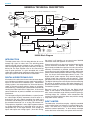
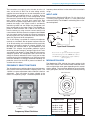
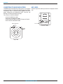
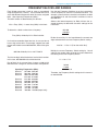
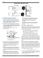
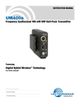
UH400A
FREQUENCY AGILE
PLUG-ON UHF TRANSMITTER
Featuring Digital Hybrid Wireless™ Technology
U.S. Patent Pending
OPERATING INSTRUCTIONS
LECTROSONICS, INC.
Rio Rancho, NM
www.lectrosonics.com
UH400
2
LECTROSONICS, INC.
Frequency Agile Plug-on UHF Transmitter
Thank you for selecting the Lectrosonics UH400A frequency agile, plug-on transmitter. The UH400 combines over
80 years of engineering experience with the very latest components, in a design that addresses the most
demanding professional applications.
The design of the UH400A was the direct result of numerous conversations with users, staging and touring
companies and dealers across the US. The specific concerns and needs brought up in these conversations led
directly to the development of the operational features offered on the UH400A. Two hundred fifty six frequencies
are user selectable in 100 kHz steps to alleviate interference problems in travelling venues.
The UH400A is a rugged, machined aluminum package. Selectable voltage phantom power is provided allowing
the UH400 to be used with the widest variety of microphones. LEDs located on the UH400A front panel make quick
and accurate level settings without having to view the receiver. The battery compartment accepts any 9 volt
alkaline or lithium battery and makes a positive connection via self-adjusting contacts.
Only the UH400A transmitter is covered in this manual. Companion receivers are covered in separate manuals.
The UH400A will operate with any 100, 200 or 400 Series Lectrosonics receiver in the same frequency group.
TABLE OF CONTENTS
GENERAL TECHNICAL DESCRIPTION ...................................................................................... 4
INTRODUCTION .................................................................................................................... 4
DIGITAL HYBRID TECHNOLOGY ......................................................................................... 4
INPUT LIMITER ...................................................................................................................... 4
NO PRE-EMPHASIS/DE-EMPHASIS .................................................................................... 5
PILOT TONE SQUELCH ....................................................................................................... 5
WIDE-BAND DEVIATION ....................................................................................................... 5
LONG BATTERY LIFE ........................................................................................................... 5
FREQUENCY AGILITY .......................................................................................................... 5
POWER SWITCH ................................................................................................................... 6
POWER ON/OFF LED ............................................................................................................ 6
CONTROLS AND FUNCTIONS .................................................................................................... 6
PHANTOM POWER VOLTAGE SELECT SWITCH .............................................................. 6
FREQUENCY SELECT SWITCHES ...................................................................................... 7
INPUT JACK ........................................................................................................................... 7
MODULATION LEDS ............................................................................................................. 7
COMPATIBILITY MODE INDICATORS ................................................................................. 8
MIC LEVEL ............................................................................................................................. 8
FREQUENCY BLOCKS AND RANGES ....................................................................................... 9
OPERATING INSTRUCTIONS ................................................................................................... 10
ATTACHING THE MICROPHONE ....................................................................................... 10
MIC LEVEL OPERATING TIP .............................................................................................. 10
SELECTING THE COMPATIBILITY MODE ......................................................................... 10
ADJUSTING THE TRANSMITTER FREQUENCY ............................................................... 11
BATTERY REPLACEMENT ................................................................................................. 11
TROUBLESHOOTING ................................................................................................................ 12
SPECIFICATIONS AND FEATURES ......................................................................................... 13
SERVICE AND REPAIR ............................................................................................................. 14
RETURNING UNITS FOR REPAIR ............................................................................................ 14
LIMITED ONE YEAR WARRANTY ............................................................................... Back Cover
The UH400 transmitter is FCC type accepted under Part 74: 470 - 608MHz and 614 - 806MHz
Rio Rancho, NM – USA
3
UH400
GENERAL TECHNICAL DESCRIPTION
+5V / +15V / +48V
BIAS SUPPLY
INPUT
JACK
Hi/Lo
Pass
Filter
<-- (See Input Jack under Controls and Functions for details.)
Input
Amp
Audio
Audio
Level
Shunt
Limiter
A-D
Converter
D-A
Converter
11001001
11001001
Encoded
Audio +
Pilot Tone
Switching
Power
Supply
Digital Signal Processor
9V
+3.3v
+3.2v
+1.8v
+6v
-3v
Bicolor
Power
LED
Microprocessor
Bicolor
Modulation
LEDs
Freq
Switches
Phase Locked Loop
Voltage
Controlled
Oscillator
11.3 MHz
Reference
50
Isolator
Transmitter
UH400 Block Diagram
INTRODUCTION
The 400 system uses ±75 kHz wide deviation for an extremely high signal to noise ratio. The switching power
supplies provide constant voltages to the transmitter circuits from the beginning (9.3 volts) to the end (5.5 volts) of
battery life. The input amplifier uses an ultra low noise op
amp for quiet operation. It is gain controlled with a wide
range dual envelope input compressor which cleanly limits
input signal peaks over 30 dB above full modulation.
DIGITAL HYBRID TECHNOLOGY
All wireless links suffer from channel noise to some degree,
and all wireless microphone systems seek to minimize the
impact of that noise on the desired signal. Conventional
analog systems use compandors for enhanced dynamic
range, at the cost of subtle artifacts (known as “pumping”
and “breathing”). Wholly digital systems defeat the noise by
sending the audio information in digital form, at the cost of
some combination of power, bandwidth and resistance to
interference.
The Lectrosonics Digital Hybrid WirelessTM system (hereafter called Digital Hybrid) overcomes channel noise in a
dramatically new way, digitally encoding the audio in the
transmitter and decoding it in the receiver, yet still sending
the encoded information via an analog FM wireless link.
This proprietary algorithm is not a digital implementation of
an analog compandor but a technique which can be accomplished only in the digital domain, even though the
inputs and outputs are analog signals. (As of this writing,
4
the patent is still pending, so we cannot reveal detailed
information about the algorithm at this time.)
Channel noise still has an impact on received signal quality
and will eventually overwhelm the receiver. The Digital
Hybrid simply encodes the signal to use a noisy channel as
efficiently and robustly as possible, yielding audio performance that rivals that of wholly digital systems, without the
power and bandwidth problems inherent in digital transmission. As always, these advantages come at a cost. The
Digital Hybrid system requires fairly intensive digital processing in both the transmitter and the receiver. These
processors cost money, take up space and consume power.
The Digital Hybrid system also requires that the underlying
RF link be of excellent quality, with better frequency response and distortion characteristics than that required by
conventional systems.
Because it uses an analog FM link, the Digital Hybrid
enjoys all the benefits of conventional FM wireless systems, such as excellent range, efficient use of RF spectrum,
and long battery life. However, unlike conventional FM
systems, the Digital Hybrid has done away with the analog
compandor and its artifacts.
INPUT LIMITER
The 400 series transmitters employ a digitally-controlled
analog audio limiter just before the analog-to-digital converter. The limiter has a range of more than 30 dB for
excellent overload protection. A dual release envelope
makes the limiter acoustically transparent while maintain-
LECTROSONICS, INC.
Frequency Agile Plug-on UHF Transmitter
ing low distortion. It can be thought of as two limiters in
series, connected as a fast attack and release limiter followed by a slow attack and release limiter. The limiter
recovers quickly from brief transients, so that its action is
hidden from the listener, but recovers slowly from sustained high levels, to both keep audio distortion low and
preserve short term dynamic changes.
The Modulation LEDs indicate limiter activity. When the 20 LED glows red and the -10 LED glows green with
occasional red flickers, this indicates that the limiter is
active and that the transmitter is fully modulated (audio
level is between +0 and +10 dB). When the -10 LED glows
solid red, this indicates that the level is +10 dB or more into
limiting. Occasional forays by the -10 LED into the red are
desirable for most applications, since the distortion introduced by the limiter is so minimal and full modulation is
thus assured. We strongly recommend setting the audio
level of the transmitter high enough so that the -10 LED
occasionally flickers red.
Generally speaking, some limiting is desirable in normal
operation to improve the signal to noise ratio of the system.
The limiting action is not audible and does not create
distortion. A highly trained ear would hear only the compression of the peaks in the audio signal, which is desirable
with most recorders and many sound reinforcement systems.
NO PRE-EMPHASIS/DE-EMPHASIS
The signal to noise ratio of the 400 system is high enough
to preclude the need for conventional pre-emphasis (HF
boost) in the transmitter and de-emphasis (HF roll off) in
the receiver. Pre-emphasis and de-emphasis in an FM
radio system usually provides about a 10 dB improvement
in the signal to noise ratio of the system, but the high
frequency boost in the transmitter must be removed in a
purely complementary manner or else the frequency response of the original audio signal will be altered.
PILOT TONE SQUELCH
The 400 system utilizes one of 256 different ultrasonic
tones between 25 and 32 kHz, that modulate the carrier to
operate the receiver squelch. The pilot tone frequency is
chosen according to which of the 256 channels has been
selected by the frequency switch setting. The basic benefit
of the pilot tone squelch system is that the receiver will
remain muted until it receives the pilot tone from the matching transmitter, even if a strong RF signal is present on the
carrier frequency of the system. The UH400 extends this
concept even further by insuring that all transmitters in a
system have different pilot tone frequencies so that even
spurious RF from the wrong transmitters can’t open the
receiver squelch.
WIDE-BAND DEVIATION
A ±75 kHz deviation improves the capture ratio, signal to
noise ratio and AM rejection of a wireless system dramatically, compared to the more commonly used ±15 kHz
deviation.
LONG BATTERY LIFE
Switching power supplies throughout the design allow over
4.5 hours of operation using a single 9 volt alkaline battery.
(A 9 volt lithium battery will provide over 12 hours of
operation.) The battery contacts are spring loaded to
prevent “rattle” as the unit is handled.
FREQUENCY AGILITY
The transmitter section uses a synthesized, frequency selectable main oscillator. The frequency is extremely stable
over a wide temperature range and over time.
Two rotary switches, located on the side panel of the unit,
provide 256 frequencies in 100 kHz steps over a 25.5 MHz
range. This alleviates carrier interference problems in
mobile or traveling applications.
Pre-emphasis can also cause distortion in the receiver. As
this signal is passed through the IF filters in the receiver,
distortion can be produced, most noticeably at full modulation. De-emphasis cannot be applied until the signal is
converted into audio, so there is no way around this problem short of eliminating pre-emphasis altogether. Neither
of these problems occur in the 400 system
Rio Rancho, NM – USA
5
UH400
CONTROLS AND FUNCTIONS
MODULATION LEDs
–10
–20
INPUT
JACK
POWER
ON/OFF
LED
FREQUENCY
1.6MHz 100kHz
POWER
SWITCH
NO PHTM
INPUT
JACK
MIC LEVEL
Top View
PHTM
LEVEL
5V
48
PWR OFF
POWER SWITCH
The three position OFF/PHTM/NO PHTM Power Switch
turns the unit on or off, and selects either phantom power,
or no phantom power. Regardless of which position the
switch is set, the pilot tone muting system effectively prevents “thumps” or transients from occurring during power
up or power down.
The PHTM (center) position of the power switch turns on
the phantom power value selected by the Phantom Power
Voltage Select switch, while the NO PHTM (fully on) position disables phantom power.
Note
In order to minimize accidents, be careful to use
the center (PHTM) position only when necessary
and keep the Phantom Power Voltage Select switch
in the 5 V position. (See Phantom Power Voltage
Select switch.)
POWER ON/OFF LED
This LED glows green when the battery is good. When the
lamp glows red, there are about 30 minutes of operation
left with the recommended lithium battery, and about 20
minutes of battery life left with an alkaline battery. The lamp
will flash red when there are only a few minutes of life
remaining in either type of battery.
Note
A NiMH battery will give little or no warning when
it is depleted. If you wish to use NiMH batteries in
this unit, we recommend installing a fully charged
batteries, noting the length of time that the
batteries will run the unit and in the future use
somewhat less than that time to determine when the
battery needs to be replaced.
F 0 1
2
E
3
4
5
A
9 8 7
6
F 0 1
2
3
4
5
D
C
B
A
9 8 7
6
FREQUENCY SWITCHES
(BEHIND DOOR)
V
PHANTOM POWER
VOLTAGE SELECT
(RECESSED)
15V
Side View
Control Panel
This transmitter may be used with a wide variety of microphones. The 3-pin XLR connector allows the transmitter to
be used with any dynamic microphone, as well as many
two wire positive bias lavaliere systems (such as those
systems supplied by Lectrosonics).
6
E
D
C
B
A weak battery will sometimes light the POWER LED to the
“good” green indication immediately after being put in the
unit, but will soon discharge to the point where the LED will
go red or shut down (just like a flashlight with “dead”
batteries). If the Power LED fails to light when power is
applied, replace the battery.
PHANTOM POWER VOLTAGE SELECT
SWITCH
This switch selects from three phantom voltages when the
PWR switch is in the mid position. The voltages are:
• 5 volts for lavaliere microphones,
• 15 volts for some professional mics requiring high
current and for many common stage mics that will
operate over a wide phantom voltage range of 12
to 48 volts. With the proper adapter, this position
can also be used with T power microphones. See
our web site for details on finding or making the
proper adapter.
• 42 volts for microphones that do in fact require a
supply greater than 15 volts. (See below for a
discussion of why 42 and not a “true” 48 volts.)
For longest battery life use the minimum phantom voltage
necessary for the microphone. Many stage microphones
regulate the 48 volts down to 10 volts internally anyway, so
you might as well use the 58 volt setting and save some
battery power. If you are not using a microphone for the
input device, or are using a microphone that does not
require phantom power, set the Power Switch to the No
PHTM position (No Phantom Power). This is the fully up
position of the Power Switch. Phantom power should only
be used with a fully floating, balanced device such as most
microphones with a 3-pin XLR connector. If you use the
phantom power with an unbalanced device or if pins 2 or 3
are DC connected to ground, then you will draw maximum
current from the power supply. The UH400A is fully protected against such shorts but the 9 volt battery will be
drained at twice its normal rate.
LECTROSONICS, INC.
Frequency Agile Plug-on UHF Transmitter
The transmitter can supply 4 mA at 42 volts, 8 mA at 15
volts, and 8 mA at 5 volts. The 42 volts setting actually
supplies the same voltage to a 48 volt microphone as the
DIN standard arrangement due to a dynamic biasing
scheme that does not have as much voltage drop as the
DIN standard. The 48 volt DIN standard arrangement protects against shorts and high fault current with high
resistance in the power supply feeds to pins 2 and 3. This
protects the supply if the supply current is accidentally
shorted to ground and also keeps the microphone from
being attenuated by the power supply. The UH400A improves on those functions and is able to use less power
from the battery by using constant current sources and
current limiters. With this dynamic arrangement the UH400A
can also supply more than twice the current of competing
48 volt plug on units and provide four times the current to
some very high end 18 volt microphones.
The 5 volt setting is provided for lavaliere microphones
made by us and others. Do not power lavalieres from the
15 or 48 volt setting as the microphone will be most likely
destroyed. Lectrosonics makes an adapter, MCA5X, that
will adapt our standard TA5F 5 pin microphones to the
UH400A. This adapter also provides protection against
excessive phantom voltage. If voltages higher than 5 volts
are applied to the adapter, a Zener diode will shunt excess
voltage to ground. The microphone won't work until the
voltage is correctly reduced to 5 volts. If you have an older
lavaliere mic that was wired directly to an XLR for use with
the earlier UH200's, we strongly recommend building our
protection circuit into the XLR to prevent accidental destruction of the lavaliere.
FREQUENCY SELECT SWITCHES
Two 16 position rotary switches adjust the center frequency
of the carrier within the transmitter’s frequency block. The
1.6 MHz is a coarse adjustment and the 100 kHz is the fine
adjustment. Each transmitter is factory aligned at the
center of its operating range. The default position of the
frequency select switches is in the center of the transmitter’s
range.
INPUT JACK
Standard 3-pin Switchcraft XLR type. Pin 2 is signal, pin 3
is a floating signal ground, and pin 1 is case ground (see
schematic below). The UH400A is self-locking onto a standard microphone.
To Mic
Preamp
+5V / +18V / +42V
I
1uh
1000
1uh
4.7uf
1
2
3
1uh
Input Jack Schematic
Note
If severe noise is experienced when the microphone
is moved with respect to the UH400A, the cause is
an unbalanced condition between pins 2 and 3 of
the microphone.
MODULATION LEDS
The Modulation LEDs indicate the proper setting of the
MIC LEVEL control. There are two bicolor modulation LEDs
that can light either red or green depending on the amount
of gain applied. The transmitter should be set so that both
LEDs glow green, with the -20 LED occassionally blinking
red.
MODULATION LEDs
–10
–20
Top View
Signal Level
Left Switch
1.6 MHz
Right Switch
100 kHz
Frequency Select Switches
Less than -20 dB
-20 dB to -10 dB
-10 dB to +0 dB
+0 dB to +10 dB
Greater than +10 dB
Rio Rancho, NM – USA
-20 LED -10 LED
Off
Green
Green
Red
Red
Off
Off
Green
Green
Red
7
UH400
COMPATIBILITY MODE INDICATORS
MIC LEVEL
The Modulation LEDS will blink when power is first applied
to the transmitter to indicate the selected operating mode.
Immediately after, all LEDS will blink together red, then
green, followed by the Modulation LEDs (-20 and -10)
blinking to indicate the operating mode.
Used to adjust the audio input level for the proper modulation.
The –20 and –10 LEDs will blink:
• Once for 100 Series mode
• Two times for 200 Series mode
• Three times for mode 3 (Contact Factory for Details
• Four times for 400 Series mode
N O P HTM 5V
P HTM
MIC LEVEL
MODULATION LEDs
–10
–20
V
Control Panel
POWER
ON/OFF
LED
Top View
8
LEVEL
48
PW R O FF 1 5V
LECTROSONICS, INC.
Frequency Agile Plug-on UHF Transmitter
FREQUENCY BLOCKS AND RANGES
Each UH400 transmitter is built to cover a pre-selected
range of frequencies (a “block”). The transmitter will tune to
any of 256 different frequencies within this factory assigned
block. (See Operating Frequencies (MHz).)
The block number is determined by this formula:
25.6 × Freq. (MHz) = Lowest freq. (MHz) in the block
Use the two Frequency Switches to set the transmitter’s
carrier frequency to match the associated receiver. For
example, assume that the transmitter and receiver are both
assigned Block 25 and the receiver’s switches are set to
658.400 MHz.
Subtract the lowest frequency for Block 25 from the assigned frequency to determine the switch settings for the
transmitter.
To determine a block number from a frequency:
658.400
-640.000
18.400
Freq. (MHz) divided by 25.6 = Block number
It is handy to remember these formulas, in case you do not
have a copy of the table. For example, suppose you need
to know which block covers 685.500 MHz, without using the
table:
685.500 divided by 25.6 = 26.77734375
The first two digits left of the decimal are the block number.
In this case, 685.500 MHz falls within block 26.
Divide the result by 1.6 and round down the nearest two
digits to determine the coarse Frequency Switch setting.
18.4/1.6 = 11.5 or 11 (B on the switch dial)
Multiply the coarse Frequency Switch setting by 1.6 and
subtract that number from the original result to determine
the setting for the fine Frequency Switch.
11 x 1.6 = 17.6
Part of block 23 is not used since it covers a 608 to 614
MHz band that is illegal for use with wireless microphones.
Operating Frequencies (MHz):
Block 21
537.600 - 563.100
Block 22
563.200 - 588.700
Block 23
588.8 00- 607.900;
614.100 - 614.300
Block 24
614.400 - 639.900
Block 25
640.000 - 665.500
Block 26
665.600 - 691.100
Block 27
691.200 - 716.700
Block 28
716.800 - 742.300
Block 29
742.400 - 767.900
Block 30
768.000 - 793.500 (export only)
18.400
- 17.600
.800 or 8
Therefore, the Frequency Switch settings for this transmitter would be B8.
Rio Rancho, NM – USA
9
UH400
OPERATING INSTRUCTIONS
TO ATTACH
Hold the
transmitter
case and
rotate the
collar in the
direction
shown. Do
this over a
soft surface
as the
microphone
may pop off
suddenly
Press firmly, listen for click.
Depress collar fully.
Click!
TO REMOVE
Pull on mic to insure locking.
ATTACHING THE MICROPHONE
1. Insert the UH400A into the XLR connector on the
bottom of the selected microphone. Listen for the
“click” that indicates the transmitter assembly has
locked on to the microphone. Gently pull on the mic
to insure proper locking has occurred.
2. If necessary, set the phantom power voltage for the
mic. If the mic does not require phantom voltage, set
the Phantom Power Voltage Select switch to 5V to
reduce the possibility of damage to the mic when the
transmitter is powered up.
3. Set the MIC LEVEL control to minimum (fully
counterclockwise).
same level that will be used during the program.
Increase the Mic LEVEL control until the -20 LED
glows red and the -10 dB glows green with
occasionally red flickers. This indicates full
modulation.
6. Once the gain has been adjusted, the remainder of
the audio sound system can be energized and
adjusted.
MIC LEVEL OPERATING TIP
The Mic LEVEL control should not be used to control the
volume of your sound system or recorder levels. The Mic
LEVEL control matches the transmitter gain with the user’s
voice level and mic’s position.
If the audio level is too high — both red LEDs will
glow solid red. This condition may reduce the
dynamic range of the audio signal.
POWER
SWITCH
N O P HTM 5V
P HTM
LEVEL
48
V
PW R O FF 1 8V
PHANTOM POWER
VOLTAGE SELECT
Control Panel
4. Turn on the transmitter by setting the Power Switch
to PHTM, if the mic requires phantom power, or to
NO PHTM, if the mic does not require phantom
power. (Refer to the specifications for the mic you
are using to determine if phantom power is
required.)
5. Hold the mic as you will when you will be using it, or
if the mic will be stationary, such as attached to a
lectern or mic stand and speak or sing into it at the
same voice level that will be actually used during the
program.
5. Start with the Mic LEVEL control at maximum
counterclockwise, then observe the front panel
Modulation LEDs. Slowly turning the Audio LEVEL
control clockwise while talking into the mic at the
10
If the audio level is too low — neither LED will
glow, or only the –20 LED will glow green. This
condition may cause hiss and noise in the audio.
Different voices will usually require different settings of the
Mic LEVEL control, so check this adjustment as each new
person uses the system. If several different people will be
using the transmitter and there is not time to make the
adjustment for each individual, adjust it for the loudest
voice.
SELECTING THE COMPATIBILITY MODE
This unit is capable of working with Lectrosonics 400 series digital hybrid receivers or 200 and 100 Series analog
receivers. It is also capable of working with analog wireless receivers from other manufacturers (contact the factory
for details). The transmitter can be easily set to the compatibility mode of the matching receiver using only the
supplied screwdriver and a battery.
NOTE: The UH400A is supplied from the factory as a
400 series transmitter
1. Ensure the battery is good. If the Power LED lights up
when the Power Switch is set to PHTM or NO PHTM, the
battery is good and correctly installed.
2. Turn off the transmitter.
LECTROSONICS, INC.
Frequency Agile Plug-on UHF Transmitter
3. With a small screwdriver (included with your unit), set
the frequency change switches to CC. (for Change,
Change). To gain access to these switches, slide the
access door open with a fingernail.
operating frequency in 100 kHz steps to find a clear channel. If it is not possible to find a clear channel using the 100
kHz switch, return it to its original position and change the
1.6 MHz switch by one click then try the 100 kHz switch
again.
BATTERY REPLACEMENT
E
D
C
B
A
F 0 1
2
3
4
5
9 8 7
6
Left Switch
1.6 MHz
E
D
C
B
A
F 0 1
The UH400A transmitter is powered by a standard alkaline
9 volt battery. It is important that you use ONLY ALKALINE
OR LITHIUM batteries for longest life. Standard zinc-carbon
batteries marked “heavy duty” or “long-lasting” are not
adequate. They will provide only about five minutes of
operation. Similarly, ni-cad rechargeable batteries only
give one hour of operation, and will also run down quite
abruptly. Alkaline batteries provide about 4.5 hours of
operation while lithium batteries will run the unit for about
12 hours.
2
3
4
5
9 8 7
6
RELEASE
DOOR
SWING OPEN
OBSERVE
POLARITY
Right Switch
100 kHz
Frequency Select switches
4. Set the Power Switch to NO PHTM briefly – just a couple
of seconds for the front panel LED’s to light up, then
immediately turn the unit off.
5. Change the Frequency Select switches to one of the
following settings:
MODE
SWITCH SETTINGS
100 Series
200 Series
Mode 3*
400 Series Digital Hybrid
1,1
2,2
3,3 (Contact factory for details.)
4,4
6. Turn the transmitter on, when the front panel LEDs light
up, immediately turn the unit off.
7. Change the switches to 0,0.
8. Energize the transmitter and verify the new compatibility
mode. The front panel –20 and –10 LEDs will blink:
• Once for 100 Series mode
• Two times for 200 Series mode
• Three times for mode 3 (Contact Factory for Details
• Four times for 400 Series mode
The Compatibility Mode will remain set until changed with
the above procedure.
ADJUSTING THE TRANSMITTER
FREQUENCY
Battery Compartment Action
To open the battery compartment, press upward on the
cover door in the direction of the arrow as shown in the
drawing. Only slight, sliding pressure is needed to open
and close the battery door.
Swing the door open and take note of the location of the
positive (+) and negative (-) terminals. Insert the new
battery correctly and close the cover by reversing the
opening procedure. Note that the battery door will NOT
close if the battery is inserted incorrectly, since the terminals will hit a protective polarity barrier. Don’t force the
battery door closed. If it is difficult to close, the battery is in
backwards.
The battery life will be affected by the amount of phantom
power supplied to any microphones that require it. A high
drain 48 volt microphone can shorten battery life by 40% or
more. A light drain 18 volt microphone will make little or no
difference in battery life. The only way to be sure is to test
the transmitter and microphone combination with a brand
new battery. Then will you be sure of the combination's
battery life.
CAUTION
If you are experiencing interference from another signal on
your frequency, you may want to change the operating
frequency of your system. This is done with the Frequency
Switches.
The left switch changes the operating frequency by 1.6
MHz per step and the right switch changes it 100 kHz per
step. If you are experiencing interference, change the
Lithium batteries will expand and swell if allowed to go into a deep
discharge. Be sure to remove lithium batteries as soon as the
battery is depleted. If lithium batteries are allowed to fully discharge
while still inside the battery compartment, they will be very difficult
to remove. Stuck lithium batteries can be avoided by removing the
label wrapping around the battery before use. This will allow the
battery to swell but will still leave enough room in the compartment
for the battery to fall out normally.
Rio Rancho, NM – USA
11
UH400
TROUBLESHOOTING
Before going through the following chart, be sure that you have a good battery in the transmitter. It is important that you
follow these steps in the sequence listed.
SYMPTOM
POSSIBLE CAUSE
TRANSMITTER BATTERY LED OFF
1. Battery is inserted backwards.
2. Battery is dead.
NO TRANSMITTER MODULATION LEDs
1.
2.
3.
4.
5.
RECEIVER RF LAMP OFF
1.
2.
3.
4.
NO SOUND (OR LOW SOUND LEVEL),
RECEIVER MOD LEVEL LEDs ARE ON
NO SOUND (OR LOW SOUND LEVEL),
RECEIVER MOD LEDs ARE OFF
Gain control turned all the way down.
Battery is in backwards. Check power LED.
Mic capsule is damaged or malfunctioning.
Mic cable damaged or mis-wired.
Phantom power not enabled for mic that requires it.
Transmitter not turned on.
Transmitter battery is dead.
Receiver antenna missing or improperly positioned.
Transmitter and receiver not on same frequency. Check
switches/display on transmitter and receiver.
5. Operating range is too great.
1. Receiver output level set too low.
2. Receiver output is disconnected; cable is defective or mis-wired.
3. Sound system input is turned down.
1. Transmitter gain (audio level) set too low.
2. Faulty microphone
3. Phantom power not enabled for mic that requires it.
DISTORTED SOUND
1. Transmitter gain (audio level) is far too high. Check mod level
lamps on transmitter and receiver as it is being used. (Refer to
the Operating Instructions section for details on gain adjustment)
2. Receiver output may be mismatched with the sound system or
recorder input. Adjust output level on receiver to the correct
level for the recorder, mixer or sound system.
3. Excessive wind noise or breath “pops.” Reposition microphone
and/or use a larger windscreen.
4. Transmitter is not set to same frequency as receiver. Check that
frequency select switches on receiver and transmitter match.
HISS AND NOISE – AUDIBLE DROPOUTS
1. Transmitter gain (audio level) far too low.
2. Receiver antenna missing or obstructed.
3. Operating range too great.
EXCESSIVE FEEDBACK
1. Transmitter gain (audio level) too high causing the limiter to
reduce the dynamic range which in turn causes feedback.
Check gain adjustment and/or reduce receiver output level.
(Refer to the Operating Instructions section for details on gain
adjustment)
2. Transmitter too close to speaker system.
3. Mic is too far from user’s mouth.
12
LECTROSONICS, INC.
Frequency Agile Plug-on UHF Transmitter
SPECIFICATIONS AND FEATURES
Operating frequencies:
537.600 to 607.900 MHz; 614.100 to 793.500 MHz
Frequency selection:
256 frequencies in 100 kHz steps
RF Power output:
100 mW (nominal)
Pilot tone:
25 to 32 kHz; 5 kHz deviation (in 400 Series mode)
Frequency stability:
± 0.002%
Deviation:
± 75 kHz max. (in 400 Series mode)
Spurious radiation:
60 dB below carrier
Equivalent input noise:
–118 dBV, A-weighted
Input level:
Nominal 2 mV to 300 mV, before limiting; Greater than 1.0 V maximum, with limiting.
Input impedance:
1 k Ohm
Input limiter:
Soft limiter, >30 dB range
Gain control range:
43 dB; semi-log rotary control
Modulation indicators:
Dual bicolor LEDs indicate modulation of –20, -10, 0, +10 dB referenced to
full modulation.
Low frequency roll-off:
–12 dB/octave; 70 Hz
Controls:
Control panel knob adjusts audio gain.
Rotary switches on bottom panel adjust transmitter frequency.
Audio Frequency Response:
90 Hz to 20 kHz, +/-1dB
Note
The audio is deliberately rolled off at 70Hz using a 12
dB/octave filter. This filter cannot be disabled.
Signal to Noise Ratio (dB):
SmartNR
No Limiting W/ Limiting
OFF
103.5
NORMAL
107.0
108.5
111.5
FULL
108.5
113.0
Note
The dual envelope “soft” limiter provides exceptionally
good handling of transients using variable attack and
release time constants. The gradual onset of limiting in
the design begins below full modulation, which reduces the
measured figure for SNR without limiting by 4.5 dB
Total Harmonic Distortion:
0.2% typical (400 Series mode)
Antenna:
Built in
Battery Type:
9V alkaline or lithium
Battery Life:
4.5 Hours with alkaline 9 Volt, 12 hrs with lithium (Battery life will vary with battery
brand, phantom power voltage setting and mic current drain.)
Weight:
6.5 ozs. with lithium battery, no mic
Overall Dimensions:
1.5 x 1.5 x 4.2 inches (Not including microphone.)
Emission Designator:
190KF3E
Specifications subject to change without notice.
The FCC requires that the following statement be included in this manual:
This device complies with FCC radiation exposure limits as set forth for an uncontrolled environment. This device
should be installed and operated so that its antenna(s) are not co-located or operating in conjunction with any other
antenna or transmitter.
Rio Rancho, NM – USA
13
UH400
SERVICE AND REPAIR
If your system malfunctions, you should attempt to correct or isolate the trouble before concluding that the equipment
needs repair. Make sure you have followed the setup procedure and operating instructions. Check out the interconnecting cords and then go through the TROUBLESHOOTING section in the manual
We strongly recommend that you do not try to repair the equipment yourself and do not have the local repair shop
attempt anything other than the simplest repair. If the repair is more complicated than a broken wire or loose connection,
send the unit to the factory for repair and service. Don’t attempt to adjust any controls inside the units. Once set at the
factory, the various controls and trimmers do not drift with age or vibration and never require readjustment. There are no
adjustments inside that will make a malfunctioning unit start working.
The LECTROSONICS Service Department is equipped and staffed to quickly repair your equipment. In-warranty repairs
are made at no charge in accordance with the terms of the warranty. Out-of-warranty repairs are charged at a modest flat
rate plus parts and shipping. Since it takes almost as much time and effort to determine what is wrong as it does to make
the repair, there is a charge for an exact quotation. We will be happy to quote approximate charges by phone for out-ofwarranty repairs.
RETURNING UNITS FOR REPAIR
You will save yourself time and trouble if you will follow the steps below:
A. DO NOT return equipment to the factory for repair without first contacting us by letter or by phone. We need to know
the nature of the problem, the model number and the serial number of the equipment. We also need a phone number
where you can be reached 8 a.m. to 4 p.m. (U.S.- Mountain Standard Time).
B. After receiving your request, we will issue you a return authorization number (R.A.). This number will help speed your
repair through our receiving and repair departments. The return authorization number must be clearly shown on the
outside of the shipping container.
C. Pack the equipment carefully and ship to us, shipping costs prepaid. If necessary, we can provide you with the proper
packing materials. UPS is usually the best way to ship the units. Heavy units should be “double-boxed” for safe
transport.
D. We also strongly recommend that you insure the equipment, since we cannot be responsible for loss of or damage to
equipment that you ship. Of course, we insure the equipment when we ship it back to you.
Mailing address:
Lectrosonics, Inc.
PO Box 15900
Rio Rancho, NM 87174
USA
Shipping address:
Lectrosonics, Inc.
581 Laser Rd.
Rio Rancho, NM 87124
USA
World Wide Web: http://www.lectrosonics.com
14
Telephones:
Regular:
(505) 892-4501
Toll Free
(800) 821-1121
FAX:
(505) 892-6243
Email: [email protected]
LECTROSONICS, INC.
Frequency Agile Plug-on UHF Transmitter
Rio Rancho, NM – USA
15
LIMITED
YEAR
WARRANTY
LIMITED ONE
ONE YEAR
WARRANTY
The equipment is warranted for one year from date of purchase against defects in
materials or workmanship provided it was purchased from an authorized dealer. This
warranty does not cover equipment which has been abused or damaged by careless
handling or shipping. This warranty does not apply to used or demonstrator equipment.
Should any defect develop, Lectrosonics, Inc. will, at our option, repair or replace any
defective parts without charge for either parts or labor. If Lectrosonics, Inc. cannot
correct the defect in your equipment, it will be replaced at no charge with a similar new
item. Lectrosonics, Inc. will pay for the cost of returning your equipment to you.
This warranty applies only to items returned to Lectrosonics, Inc. or an authorized
dealer, shipping costs prepaid, within one year from the date of purchase.
This Limited Warranty is governed by the laws of the State of New Mexico. It states the
entire liablility of Lectrosonics Inc. and the entire remedy of the purchaser for any
breach of warranty as outlined above. NEITHER LECTROSONICS, INC. NOR
ANYONE INVOLVED IN THE PRODUCTION OR DELIVERY OF THE EQUIPMENT
SHALL BE LIABLE FOR ANY INDIRECT, SPECIAL, PUNITIVE, CONSEQUENTIAL,
OR INCIDENTAL DAMAGES ARISING OUT OF THE USE OR INABILITY TO USE
THIS EQUIPMENT EVEN IF LECTROSONICS, INC. HAS BEEN ADVISED OF THE
POSSIBILITY OF SUCH DAMAGES. IN NO EVENT SHALL THE LIABILITY OF
LECTROSONICS, INC. EXCEED THE PURCHASE PRICE OF ANY DEFECTIVE
EQUIPMENT.
This warranty gives you specific legal rights. You may have additional legal rights which
vary from state to state.
LECTROSONICS, INC.
581 LASER ROAD
RIO RANCHO, NM 87124 USA
www.lectrosonics.com
June 24, 2004