1
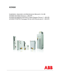
INSTALLATION AND OPERATION MANUAL
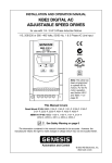
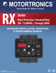
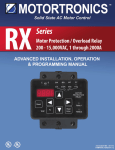
KBN2 DIGITAL AC
ADJUSTABLE SPEED DRIVES
for Use with 1/2 - 30 HP Inverter Duty, TEFC and TENV 3-Phase Induction Motors
208/230 or 380 - 460 Volts, 50/60 Hz, 1 & 3 Phase AC Line Input
SEQ
FRQ
FWD
REV
Hz/RPM
VOLT
FUN
AMP
RUN
STOP
DSP
FUN
FWD
REV
RESET
LISTED
16KJ.
POWER CONV.EQ
E177007
ISO
9002
READ
ENTER
0
100
FREQ.SET
NDOP-01
Note: This drive has
been programmed
to operate 60 Hz
motors. For 50 Hz
motor operation,
see Section VIII-C-2,
on page 32.
* See Note 1, on page 10.
This Manual Covers Models:
KBN2-2250-1, 2201-1, 2202-1, 2203-1, 2305-1, 2307-1, 2310-1, 2315-1, 2320-1, 2330-1,
4301-1, 4302-1, 4303-1, 4305-1, 4307-1, 4310-1, 4315-1, 4320-1, 4330-1
!
See Safety Warning on page 6
The information contained in this manual is intended to be accurate. However, the
manufacturer retains the right to make changes in design which may not be included herein.
Automation and Control
© 2003 KB Electronics, Inc.
(See back cover)
TABLE OF CONTENTS
Section
i.
Page
Simplified Instructions . . . . . . . . . . . . . . . . . . . . . . . . . . . . . . . . . . . . . . . . . . . . . . . . . . . . . . . . . . . . . 5
ii.
Safety Warning . . . . . . . . . . . . . . . . . . . . . . . . . . . . . . . . . . . . . . . . . . . . . . . . . . . . . . . . . . . . . . . . . . 6
I.
Introduction . . . . . . . . . . . . . . . . . . . . . . . . . . . . . . . . . . . . . . . . . . . . . . . . . . . . . . . . . . . . . . . . . . . . . 6
II.
Mounting Instructions . . . . . . . . . . . . . . . . . . . . . . . . . . . . . . . . . . . . . . . . . . . . . . . . . . . . . . . . . . . . 15
III.
Reconditioning the Bus Capacitors . . . . . . . . . . . . . . . . . . . . . . . . . . . . . . . . . . . . . . . . . . . . . . . . . . 15
IV.
Terminal Block TM1 Wiring Instructions (Power Connections) . . . . . . . . . . . . . . . . . . . . . . . . . . . . . . 15
V.
Terminal Block TM2 Wiring Instructions (Signal Connections) . . . . . . . . . . . . . . . . . . . . . . . . . . . . . . 17
A. External Run/Stop-Forward/Reverse Connection . . . . . . . . . . . . . . . . . . . . . . . . . . . . . . . . . . . . . 18
B. External Frequency Control . . . . . . . . . . . . . . . . . . . . . . . . . . . . . . . . . . . . . . . . . . . . . . . . . . . . . 19
C. Multifunction Output Relay Connection . . . . . . . . . . . . . . . . . . . . . . . . . . . . . . . . . . . . . . . . . . . . 24
D. Multifunction Analog Output Connection . . . . . . . . . . . . . . . . . . . . . . . . . . . . . . . . . . . . . . . . . . . 24
E. Multifunction Open Collector Output Connection . . . . . . . . . . . . . . . . . . . . . . . . . . . . . . . . . . . . . 24
F. Reset Connection . . . . . . . . . . . . . . . . . . . . . . . . . . . . . . . . . . . . . . . . . . . . . . . . . . . . . . . . . . . . 25
G. RS-232 or RS-485 Communication Cable Connection . . . . . . . . . . . . . . . . . . . . . . . . . . . . . . . . . 25
VI.
AC Line Fusing . . . . . . . . . . . . . . . . . . . . . . . . . . . . . . . . . . . . . . . . . . . . . . . . . . . . . . . . . . . . . . . . . 25
VII.
Recommended High Voltage Dielectric Withstand Testing (Hi-Pot) . . . . . . . . . . . . . . . . . . . . . . . . . . 25
VIII. Drive Operation . . . . . . . . . . . . . . . . . . . . . . . . . . . . . . . . . . . . . . . . . . . . . . . . . . . . . . . . . . . . . . . . . 27
A. Digital Keypad Description . . . . . . . . . . . . . . . . . . . . . . . . . . . . . . . . . . . . . . . . . . . . . . . . . . . . . . 27
B. Digital Keypad Operation . . . . . . . . . . . . . . . . . . . . . . . . . . . . . . . . . . . . . . . . . . . . . . . . . . . . . . . 29
1. Setting Drive Output Frequency Using the Keypad . . . . . . . . . . . . . . . . . . . . . . . . . . . . . . . . . 29
2. Programming the Drive . . . . . . . . . . . . . . . . . . . . . . . . . . . . . . . . . . . . . . . . . . . . . . . . . . . . . . 29
C. Important Programming Functions . . . . . . . . . . . . . . . . . . . . . . . . . . . . . . . . . . . . . . . . . . . . . . . . 31
1. Motor Current Rating [F070] . . . . . . . . . . . . . . . . . . . . . . . . . . . . . . . . . . . . . . . . . . . . . . . . . . 31
2. 60 Hz, 50 Hz Motor Operation (Volts/Hz Pattern) [F005] . . . . . . . . . . . . . . . . . . . . . . . . . . . . . 32
3. AC line Input Voltage [F030] . . . . . . . . . . . . . . . . . . . . . . . . . . . . . . . . . . . . . . . . . . . . . . . . . . 32
D. Other Useful Programming . . . . . . . . . . . . . . . . . . . . . . . . . . . . . . . . . . . . . . . . . . . . . . . . . . . . . . 33
1. External Run/Stop-Forward/Reverse Control [F010] . . . . . . . . . . . . . . . . . . . . . . . . . . . . . . . . 33
2. External Forward-Stop-Reverse Control [F003] . . . . . . . . . . . . . . . . . . . . . . . . . . . . . . . . . . . . 33
3. Frequency Control Method [F011] . . . . . . . . . . . . . . . . . . . . . . . . . . . . . . . . . . . . . . . . . . . . . . 34
4. Analog Signal Input Scaling [F026, F027, F028, F029] . . . . . . . . . . . . . . . . . . . . . . . . . . . . . . 35
5. Manual and Automatic Restart [F010, F016, F032, F035] . . . . . . . . . . . . . . . . . . . . . . . . . . . . 37
6. Load Regulation and Torque Boost [F047, F072, F005, F075, F076, F070] . . . . . . . . . . . . . . 39
7. Display Modes [F047, F051, F052] . . . . . . . . . . . . . . . . . . . . . . . . . . . . . . . . . . . . . . . . . . . . . 43
E. Programmable Functions (Summary) . . . . . . . . . . . . . . . . . . . . . . . . . . . . . . . . . . . . . . . . . . . . . . 46
IX.
Programmable Functions (Detailed) . . . . . . . . . . . . . . . . . . . . . . . . . . . . . . . . . . . . . . . . . . . . . . . . . . 53
X.
Optional Accessories . . . . . . . . . . . . . . . . . . . . . . . . . . . . . . . . . . . . . . . . . . . . . . . . . . . . . . . . . . . . . 76
XI.
Limited Warranty . . . . . . . . . . . . . . . . . . . . . . . . . . . . . . . . . . . . . . . . . . . . . . . . . . . . . . . . . . . . . . . . 80
Tables
Page
1.
Model Number Identification . . . . . . . . . . . . . . . . . . . . . . . . . . . . . . . . . . . . . . . . . . . . . . . . . . . . . . . . 9
2.
General Performance Specifications . . . . . . . . . . . . . . . . . . . . . . . . . . . . . . . . . . . . . . . . . . . . . . . . . . 9
3.
Electrical Ratings . . . . . . . . . . . . . . . . . . . . . . . . . . . . . . . . . . . . . . . . . . . . . . . . . . . . . . . . . . . . . . . . 10
4.
Terminal Block TM1 Wiring Information . . . . . . . . . . . . . . . . . . . . . . . . . . . . . . . . . . . . . . . . . . . . . . . 16
5.
Terminal Block TM2 Wiring Information (All Models) . . . . . . . . . . . . . . . . . . . . . . . . . . . . . . . . . . . . . . 18
6.
External Run/Stop-Forward/Reverse Control [F003] . . . . . . . . . . . . . . . . . . . . . . . . . . . . . . . . . . . . . 19
ii
TABLE OF CONTENTS (Continued)
Tables (Continued)
Page
7.
Signal Input, F011, and Jumper JP1/JP2 Setting . . . . . . . . . . . . . . . . . . . . . . . . . . . . . . . . . . . . . . . 19
8.
Settings for External Up/Down Frequency Control . . . . . . . . . . . . . . . . . . . . . . . . . . . . . . . . . . . . . . . 22
9.
Selecting Preset Speed Using Multifunction Input Terminals 6, 7, 8 . . . . . . . . . . . . . . . . . . . . . . . . . . 23
10.
Recommended Fuse, Circuit Breaker, or Magnetic Contactor Rating . . . . . . . . . . . . . . . . . . . . . . . . 25
11.
LED Status Indicators . . . . . . . . . . . . . . . . . . . . . . . . . . . . . . . . . . . . . . . . . . . . . . . . . . . . . . . . . . . . 29
12.
Signal Input and Jumper JP1/JP2 Setting . . . . . . . . . . . . . . . . . . . . . . . . . . . . . . . . . . . . . . . . . . . . . 35
13A. Manual Restart for “All Faults” Including AC Power Loss - Keypad Operation . . . . . . . . . . . . . . . . . . 37
13B. Manual Restart for “All Faults” Including AC Power Loss - External Run/Stop Contacts . . . . . . . . . . 37
14A. Automatic Restart for “All Faults” Except AC Power Loss - Keypad Operation . . . . . . . . . . . . . . . . . 38
14B. Automatic Restart for “All Faults” Except AC Power Loss - External Run/Stop Contacts . . . . . . . . . . 38
15.
Automatic Restart for “All Faults” Including AC Power Loss - External Contacts . . . . . . . . . . . . . . . . 39
16.
Functions F070, F071, F075, F076, F005 Set for Widely Changing Loads . . . . . . . . . . . . . . . . . . . . 43
17.
Programmable Functions Summary List . . . . . . . . . . . . . . . . . . . . . . . . . . . . . . . . . . . . . . . . . . . 46 - 52
18.
Drive Model and Horsepower Code Setting . . . . . . . . . . . . . . . . . . . . . . . . . . . . . . . . . . . . . . . . . . . 53
19.
Preset Speeds # 1 - 7 . . . . . . . . . . . . . . . . . . . . . . . . . . . . . . . . . . . . . . . . . . . . . . . . . . . . . . . . . . . . 58
20.
Drive Model and Factory Setting of Motor Rated Current . . . . . . . . . . . . . . . . . . . . . . . . . . . . . . . . . 68
21.
Drive Model and Factory Setting of Motor No Load Current . . . . . . . . . . . . . . . . . . . . . . . . . . . . . . . 70
22.
Fault Codes and Corrective Actions . . . . . . . . . . . . . . . . . . . . . . . . . . . . . . . . . . . . . . . . . . . . . . 74 - 76
23.
Display Status when the Drive Is In External Start/Stop Mode . . . . . . . . . . . . . . . . . . . . . . . . . . . . . . 76
24.
RFI Filters . . . . . . . . . . . . . . . . . . . . . . . . . . . . . . . . . . . . . . . . . . . . . . . . . . . . . . . . . . . . . . . . . . . . . 78
25.
Brake Resistors . . . . . . . . . . . . . . . . . . . . . . . . . . . . . . . . . . . . . . . . . . . . . . . . . . . . . . . . . . . . . . . . . 78
26.
Extension Cables . . . . . . . . . . . . . . . . . . . . . . . . . . . . . . . . . . . . . . . . . . . . . . . . . . . . . . . . . . . . . . . . 79
Figures
1A.
Mechanical Specifications for Models
1B.
Mechanical Specifications for Models
Page
KBN2-2250-1, 2201-1 (Pkg. D) . . . . . . . . . . . . . . . . . . . . . . . . . . . . . . . . . . . . . . . . . . . . . . . . . . . . . 11
KBN2-2202-1, 4301-1, 4302-1 (Pkg. E) . . . . . . . . . . . . . . . . . . . . . . . . . . . . . . . . . . . . . . . . . . . . . . 11
1C. Mechanical Specifications for Models
KBN2-2203-1, 2305-1, 4303-1, 4305-1 (Pkg. F) . . . . . . . . . . . . . . . . . . . . . . . . . . . . . . . . . . . . . . . 12
1D. Mechanical Specifications for Models
KBN2-2307-1, 2310-1, 4307-1, 4310-1 (Pkg. G) . . . . . . . . . . . . . . . . . . . . . . . . . . . . . . . . . . . . . . . 13
1E.
Mechanical Specifications for Models
KBN2-2315-1, 2320-1, 2330-1, 4315-1, 4320-1, 4330-1 (Pkg. H) . . . . . . . . . . . . . . . . . . . . . . . . . . 14
2A.
Pkg. D, E, F, G Terminal Block TM1 Designation . . . . . . . . . . . . . . . . . . . . . . . . . . . . . . . . . . . . . . . . 15
2B.
Pkg. H Terminal Block TM1 Designation . . . . . . . . . . . . . . . . . . . . . . . . . . . . . . . . . . . . . . . . . . . . . . 15
3A.
Pkg. D, E, F, Power Connections with 1φ AC Line Input . . . . . . . . . . . . . . . . . . . . . . . . . . . . . . . . . . 16
3B.
Pkg. D, E, F, G Power Connections with 3 φ AC Line Input . . . . . . . . . . . . . . . . . . . . . . . . . . . . . . . . 16
3C. Pkg. H Power Connections . . . . . . . . . . . . . . . . . . . . . . . . . . . . . . . . . . . . . . . . . . . . . . . . . . . . . . . . 17
4.
Terminal Block TM2 Designation and General Connection Diagram (All Models) . . . . . . . . . . . . . . . . 17
5A.
Forward/Stop-Reverse/Stop Connection . . . . . . . . . . . . . . . . . . . . . . . . . . . . . . . . . . . . . . . . . . . . . . 18
5B.
Run/Stop-Forward/Reverse Connection . . . . . . . . . . . . . . . . . . . . . . . . . . . . . . . . . . . . . . . . . . . . . . 18
5C. 3-Wire Start/Stop Connection . . . . . . . . . . . . . . . . . . . . . . . . . . . . . . . . . . . . . . . . . . . . . . . . . . . . . . 18
5D. 3-Wire Start/Stop Connection with Reverse . . . . . . . . . . . . . . . . . . . . . . . . . . . . . . . . . . . . . . . . . . . 18
iii
TABLE OF CONTENTS (Continued)
Figures (Continued)
6.
Page
Typical Location of Jumper JP1/JP2 . . . . . . . . . . . . . . . . . . . . . . . . . . . . . . . . . . . . . . . . . . . . . . . . . 20
7A.
Remote Speed Potentiometer Connection . . . . . . . . . . . . . . . . . . . . . . . . . . . . . . . . . . . . . . . . . . . . 20
7B.
Jumper JP1 Set for Remote Speed Potentiometer . . . . . . . . . . . . . . . . . . . . . . . . . . . . . . . . . . . . . . 20
8A.
Voltage Following Connection . . . . . . . . . . . . . . . . . . . . . . . . . . . . . . . . . . . . . . . . . . . . . . . . . . . . . . 20
8B.
Jumper JP2 Set for 0 - 10 VDC Voltage Following Signal Input . . . . . . . . . . . . . . . . . . . . . . . . . . . . . 20
8C. Voltage Following Connection with Series Resistor . . . . . . . . . . . . . . . . . . . . . . . . . . . . . . . . . . . . . . 20
9A.
Current Following Connection . . . . . . . . . . . . . . . . . . . . . . . . . . . . . . . . . . . . . . . . . . . . . . . . . . . . . . 21
9B.
Jumper JP1 Set for Current Following Signal Input . . . . . . . . . . . . . . . . . . . . . . . . . . . . . . . . . . . . . . 21
10A. Multifunction Input Terminals Connection with Normally Open Contacts . . . . . . . . . . . . . . . . . . . . . . 21
10B. Multifunction Input Terminals Connection with Normally Closed Contacts . . . . . . . . . . . . . . . . . . . . . 21
10C. Multifunction Input Terminals Connection with Open Collector . . . . . . . . . . . . . . . . . . . . . . . . . . . . . . 22
11A. Up/Down Frequency Control Connection with Normally Open Contacts . . . . . . . . . . . . . . . . . . . . . . 22
11B. Up/Down Frequency Control Connection with Normally Closed Contacts . . . . . . . . . . . . . . . . . . . . . 22
11C. Up/Down Frequency Control Connection with Open Collector . . . . . . . . . . . . . . . . . . . . . . . . . . . . . 22
12.
Multifunction Output Relay Connection . . . . . . . . . . . . . . . . . . . . . . . . . . . . . . . . . . . . . . . . . . . . . . . 24
13.
Multifunction Analog Output Connection . . . . . . . . . . . . . . . . . . . . . . . . . . . . . . . . . . . . . . . . . . . . . . 24
14.
Multifunction Open Collector Output Connection . . . . . . . . . . . . . . . . . . . . . . . . . . . . . . . . . . . . . . . . 24
15A. Reset Connection . . . . . . . . . . . . . . . . . . . . . . . . . . . . . . . . . . . . . . . . . . . . . . . . . . . . . . . . . . . . . . . 25
15B. Reset Connection with Open Collector . . . . . . . . . . . . . . . . . . . . . . . . . . . . . . . . . . . . . . . . . . . . . . . 25
16.
Hi-Pot Setup . . . . . . . . . . . . . . . . . . . . . . . . . . . . . . . . . . . . . . . . . . . . . . . . . . . . . . . . . . . . . . . . . . . 26
17.
Digital Keypad Layout . . . . . . . . . . . . . . . . . . . . . . . . . . . . . . . . . . . . . . . . . . . . . . . . . . . . . . . . . . . . 27
18.
Flow Chart to Change Set Frequency – Drive in STOP Mode . . . . . . . . . . . . . . . . . . . . . . . . . . . . . . 30
19.
Flow Chart to Program F001 [Acceleration Time # 1] . . . . . . . . . . . . . . . . . . . . . . . . . . . . . . . . . . . . 30
20.
Input Signal Scaling . . . . . . . . . . . . . . . . . . . . . . . . . . . . . . . . . . . . . . . . . . . . . . . . . . . . . . . . . . . . . . 35
21A. Low-to-High Analog Input Signal Slope (Positive) . . . . . . . . . . . . . . . . . . . . . . . . . . . . . . . . . . . . . . . 36
21B. High-to-Low Analog Input Signal Slope (Negative) . . . . . . . . . . . . . . . . . . . . . . . . . . . . . . . . . . . . . . . 36
22.
Custom Volts/Hz Pattern for a 400 Hz - 230 Volt AC Motor . . . . . . . . . . . . . . . . . . . . . . . . . . . . . . . 44
23.
Flow Chart for Basic Display . . . . . . . . . . . . . . . . . . . . . . . . . . . . . . . . . . . . . . . . . . . . . . . . . . . . . . . 44
24.
Flow Chart Showing Motor Voltage, Bus Voltage, and
Motor Current Added to the Basic Display . . . . . . . . . . . . . . . . . . . . . . . . . . . . . . . . . . . . . . . . . . . . 44
25.
Flow Chart Showing the Basic Display Changed from
Drive Output Frequency to Motor RPM . . . . . . . . . . . . . . . . . . . . . . . . . . . . . . . . . . . . . . . . . . . . . . . 45
26.
Flow Chart Showing the Basic Display Changed from
Drive Output Frequency to Line Speed Display (Custom Units) . . . . . . . . . . . . . . . . . . . . . . . . . . . . . 45
27.
Volts/Hz Pattern . . . . . . . . . . . . . . . . . . . . . . . . . . . . . . . . . . . . . . . . . . . . . . . . . . . . . . . . . . . . . . . . 55
28.
Controlled Deceleration-to-Stop with DC Injection Braking (Rapid Stop) . . . . . . . . . . . . . . . . . . . . . . 62
29.
Analog Output Voltage Gain . . . . . . . . . . . . . . . . . . . . . . . . . . . . . . . . . . . . . . . . . . . . . . . . . . . . . . . 62
30.
Volts/Hz Curve Modification (Torque Boost) . . . . . . . . . . . . . . . . . . . . . . . . . . . . . . . . . . . . . . . . . . . . 69
31.
Recommended RFI Filter Connection . . . . . . . . . . . . . . . . . . . . . . . . . . . . . . . . . . . . . . . . . . . . . . . . 77
iv
Sec. i – Simplified Inst.
i.
SIMPLIFIED INSTRUCTIONS
IMPORTANT – You must read these simplified operating instructions before proceeding. These instructions are to be used as a reference only and are not intended
to replace the detailed instructions provided herein. You must read the Safety
Warning, on page 6, before proceeding.
It is recommended that this drive be used with Inverter Duty or TENV motors which provide full rated torque over an extended speed range without overheating. If external fan
cooling is provided, open-ventilated motors can also achieve an extended speed range
at full rated torque. A box fan or blower with a minimum of 100 CFM per HP is recommended. Mount the fan such that the motor is surrounded by the airflow.
Application Information – Some motors have low speed characteristics which cause overheating and winding failure under light or no load conditions. If the motor is operated in this
manner for an extended period of time, it is recommended that the unloaded motor current
be checked from 2 - 15 Hz (60 - 450 RPM) to ensure that the motor current does not exceed
the nameplate rating. Do not use motor if the motor current exceeds the nameplate rating.
Note: This drive has been programmed to operate 60 Hz motors. For 50 Hz motors, see
Section VIII-C-2, on page 32.
!
WARNING! Disconnect the main power when making connections to the drive.
Note: It is recommended that the bus capacitors be reconditioned if this product has been in
storage for over one year. To recondition the capacitors, apply the AC line, with the control in
the Stop Mode, for a minimum of one hour.
A. AC Line Connection – Connect the AC line to Terminals L1, L2 (for single phase AC line
input) or L1, L2, L3 (for 3-phase AC line input), of Terminal Block TM1, as described in
Section IV-A, on page 16. Be sure the AC line input voltage matches the drive rated input
voltage. See Section VIII-C-3, on page 32.
B. Ground Connection – Connect the ground wire (earth) to the ground screw as shown in
Figures 3A, 3B, and 3C, on pages 16 and 17.
C. AC Line Fusing – Install a fuse or circuit breaker in the AC line (a magnetic contactor is
recommended for models with 3-phase AC line input). Fuse each conductor that is not at
ground potential. See Section VI, on page 25, for recommended ratings.
D. Motor Connection – Connect the motor to Terminals T1 (U), T2 (V), T3 (W) of Terminal
Block TM1, as shown in Figures 3A, 3B, and 3C, on pages 16 and 17, and as described
in Section IV-C, on page 17. Motor cable length should not exceed 100 feet (30 m) - special reactors may be required - contact the Sales Department.
E. Power Up and Basic Keypad Operation – When applying power to the drive, the Drive
AC Line Input Voltage Setting [F030] will flash four times on the display and the VOLT LED
will flash. The set frequency (factory setting is “05.00”) will then flash on the display, the
VOLT LED will turn off, and the Hz/RPM LED will flash. To increase the motor speed, press
the key until the desired frequency is displayed. To decrease the motor speed, press the
key until the desired frequency is displayed. Press the RUN/STOP key to start the drive.
5
Sec. ii – Safety Warning
ii.
SAFETY WARNING
Definition of Safety Warning Symbols
Electrical Hazard Warning Symbol – Failure to observe this warning could result in
electrical shock or electrocution.
Operational Hazard Warning Symbol – Failure to observe this warning could result in
serious injury or death.
!
This product should be installed and serviced by a qualified technician, electrician, or electrical maintenance person familiar with its operation and the hazards involved. Proper
installation, which includes wiring, mounting in proper enclosure, fusing or other over current protection, and grounding can reduce the chance of electrical shocks, fires, or explosion in this product or
products used with this product, such as electric motors, switches, coils, solenoids, and/or relays. Eye
protection must be worn and insulated adjustment tools must be used when working with control
under power. This product is constructed of materials (plastics, metals, carbon, silicon, etc.) which
may be a potential hazard. Proper shielding, grounding, and filtering of this product can reduce the
emission of radio frequency interference (RFI) which may adversely affect sensitive electronic equipment. If further information is required on this product, contact the Sales Department. It is the responsibility of the equipment manufacturer and individual installer to supply this Safety Warning to the ultimate end user of this product. (SW effective 11/1992).
!
This drive contains electronic Start/Stop circuits that can be used to start and stop the drive. However
these circuits are never to be used as safety disconnects since they are not fail-safe. Use only the AC
line for this purpose.
Be sure to follow all instructions carefully. Fire and/or electrocution can result due to improper use of
this product.
This product complies with all CE directives pertinent at the time of manufacture. Contact
the Sales Department for Declaration of Conformity. (See Note 1, on page 10.)
I.
INTRODUCTION
Thank you for purchasing the GENESIS™ KBN2 Series Inverter. KB Electronics, Inc. is committed to providing total customer satisfaction by providing quality products that are easy to
install and operate.
The KBN2 series of industrial inverters are designed for 3-phase induction motors thru
30 HP. Housed in NEMA-1 enclosures, they are available with 208/230 and 380/460 Volts
AC - 50/60 Hz AC line input. The drives contain a remote mountable digital keypad with a
4-digit LED display and “status” indicators. In addition to output frequency, the display can
be programmed to indicate a variety of functions including motor voltage and current, RPM,
and custom units (Line Speed).
An isolated multifunction terminal block provides for external control of all drive operations.
The start/stop circuitry can be wired in several ways, including 2-wire and 3-wire start/stop.
In addition, three multifunction input terminals are programmable for a variety of functions
including 7 preset speeds with timers and sequence control. An output relay and open
collector output can also be programmed to allow monitoring of various parameters.
6
Sec. I – Introduction (Cont.)
Analog input signal following for 0 - 5 VDC, 0 - 10 VDC, 0 - 20 mADC, 4 - 20 mADC, and
custom input signals are also provided.
Other features include custom accel/decel curves, DC injection and dynamic braking,
auto/manual restart, and 0 - 400 Hz operation, 1 - 12 kHz switching frequency, slip compensation, and PC Windows® based RS-232/485 DriveLink™ communications.
The KBN2 contains protection features designed to prevent drive and/or motor failure due to
overload, phase-to-phase and phase-to-ground short circuit, over voltage, undervoltage,
and overtemperature. The fault codes are shown in the digital display. All models are UL
approved (USA and Canada) and 0.5 - 3 HP @ 230 Volts AC and all 460 Volt AC models are
CE and C-tick (N10980) approved.
STANDARD FEATURES
• Digital Keypad with 4-Digit LED Display and Status Indicators – Used for drive operation (Start/Stop, Forward/Reverse, and Frequency change), programming, and provides
indication of drive status (Frequency, Custom Units, Functions, Fault Codes). Contains
built-in Speed Potentiometer.
• Regenerative and DC Injection Braking – Provides controlled rapid stopping.
• Barrier Terminal Blocks – Separate terminal blocks for power (AC line, motor) and external signal input wiring (potentiometer, multifunction input/output terminals, voltage/current
following).
• 3 Multifunction Control Inputs – Provides selection of 7 Preset Speeds, Jog, Stop, and
11 other functions.
• External Forward-Stop-Reverse Control – Provides external control of motor direction
and run/stop (Forward/Stop, Reverse/Stop and Run/Stop, Forward/Reverse), and 3-wire
start/stop.
• Isolated External Signal Inputs – Provides isolated terminals for external signals to control the drive output frequency (5 kΩ potentiometer, 0 - 5 VDC, 0 - 10 VDC, 0 - 5 VDC,
0 - 20 mADC, 4 - 20 mADC). Functions F026 - F029 are used to scale the drive for a
wide range of input signals.
• Multifunction Output Relay – Provides normally open or normally closed relay contacts
for indication of Auto Start, Power Loss, Rapid Stop, Coast-to-Stop, Overtorque, and
Electronic Overload Protection.
• Output Frequency Upper Limit – Provides adjustment of output frequency upper limit
(0.01 - 400.0 Hz).
• Output Frequency Lower Limit – Provides adjustment of output frequency lower limit
(0.00 - 400.0 Hz).
• Acceleration and Deceleration Time – Provides adjustment of acceleration and deceleration time (0.1 - 3600 seconds). A second acceleration and deceleration time is available
using the multifunction input terminals.
7
Sec. I – Introduction (Cont.)
• Operates 60 Hz and 50 Hz Motors – Provides tailoring of the drive for 50 Hz or 60 Hz
motors (factory set for 60 Hz motors).
• Analog Output Voltage – Provides connections for a 0 - 10 Volt DC analog output voltage proportional to the various drive functions (F046 is factory set to “0000” [Output
Frequency]).
• Slip Compensation and Preset Volts/Hz Curves with Program Modification – Allows
tailoring the drive for constant torque, variable torque (HVAC), and widely changing loads.
• Voltage/Current Jumper – Provides selection of voltage/potentiometer or current signal
input.
• Approvals – UL (USA and Canada), CE, C-tick (N10980), ISO-9002. (See Note 1,
on page 10.)
PROTECTION FEATURES (Fault Codes are Displayed)
• Overvoltage and Undervoltage Protection – Shuts down the drive if the line voltage
goes above or below the operating range.
• Regeneration Protection – Eliminates tripping due to bus overvoltage caused by rapid
deceleration of high inertial loads.
• Trip Protection – Prevents the motor from tripping during startup of high inertial loads.
• Short Circuit Protection – Shuts down the drive if a short circuit occurs at the motor
(phase-to-phase or phase-to-ground).
• Electronic Motor Overload Protection (I2t) – Provides motor overload protection, which
prevents motor burnout and eliminates nuisance trips due to momentary overloads.
• Electronic Drive Overload Protection (I2t) – Shuts down the drive if the load current
exceeds the drive rating.
• Overtemperature Protection – Shuts down the drive if the temperature exceeds
safe limits.
OPTIONAL ACCESSORIES (See Section X, on page 79)
• RFI Filters – Provide RFI suppression to meet CE and C-tick requirements.
• Brake Resistor Kit (1 - 10 HP Models) – Provides rapid stopping of the drive.
• Digital Keypad Extension Cable Kit – 3 Ft. (1 M), 6 Ft. (2 M), and 10 Ft. (3 M) extension
cables provide remote mounting of the keypad.
• Remote Speed Potentiometer Kit – Allows remote mounting of the (5 kΩ) speed potentiometer to control motor speed.
• RS-232 or RS-485 Communication Kits – Provide PC Windows® based RS-232/485
DriveLink™ communications to facilitate programming.
• DownLoad Module™ (DLM) – Programming device uploads and downloads drive
programs.
8
Sec. I – Introduction (Cont.)
TABLE 1 – MODEL NUMBER IDENTIFICATION
KBN2
–
2
2
01 –
1
Series
Input
Phase
Input
Voltage
2: 1φ, 3φ
3: 3φ
2: 230V
4: 460V
Enclosure
Type
Horsepower
50: 0.5 HP
01: 1 HP
02: 2 HP
03: 3 HP
05: 5 HP
07: 7.5 HP
10: 10 HP
15: 15 HP
20: 20 HP
30: 30 HP
1: NEMA-1
TABLE 2 – GENERAL PERFORMANCE SPECIFICATIONS
Description
AC Line Input Voltage (VAC)
Input AC Line Frequency Range (Hz)
Output Waveform
Frequency Range (Hz)
Switching Frequency Range (kHz)
Frequency Resolution (Hz Increments)
Acceleration/Deceleration Range (Seconds)
Overvoltage Trip Point @ 230 VAC, @ 460 VAC (VAC)
1
Undervoltage Trip Point @ 230 VAC, @ 460 VAC (VAC)
Overload Rating (% for 1 Minute)
1
Specification
Factory Setting
208/230 (-10%, +15%), 380 - 460 (±10%)
220.0 / 460.0
48 - 62
—
Sine Coded PWM
—
0.01 - 400.0
60
1 - 12
10
0.01 up to 100 Hz and 0.1 above 100 Hz
—
0.1 - 3600
5
290, 580
—
140, 280
—
150
—
Output Frequency Lower Limit Range (Hz)
0.0 - 400.0
0
Output Frequency Upper Limit Range (Hz)
1.0 - 400.0
60
20
20
Braking Torque without Braking Resistor (%)
Braking Torque with Braking Resistor (%)
2
Operating Temperature Range (ºC)
Humidity (Relative, Non-Condensing) (%)
Maximum Vibration (G)
Output Relay Contact Rating (Terminals 1, 2)
Open Collector Output Rating (Terminals 10, 11)
-10 to 50
20
3
—
0.5
—
1 Amp @ 30 Volts DC, 250 Volts AC
—
5 mA at 35 VDC
4
4 - 20 mADC , Scalable
External Speed Potentiometer (Ω)
5
—
0 - 95
0 - 5 VDC, 0 - 10 VDC, 0 - 20 mADC,
External Analog Signal Input
Analog Output Voltage (Volts DC)
20 - 100
—
0 - 10 VDC
5k or 10k
—
0 - 10
—
Notes: 1. Based on 230/460 Volts nominal AC line input voltage. 2. Models KBN2-2250-1, 2201-1, 2202-1, 2203-1, 2305-1,
2307-1, 2310-1, 4301-1, 4302-1, 4303-1, 4305-1, 4307-1, 4310-1 require optional Brake Resistor to achieve maximum braking.
Braking resistor option is not available on other models. 3. In order to achieve 50 C maximum ambient temperature at full drive rating,
the top dust cover on all models thru 10 HP must be removed. Drive rating with the cover installed is 40 C. 4. To set the drive for
4 - 20 mADC input, F011 must be set to “0002”, F027 must be set to “0020”, and the jumper must be installed in the “2-3” position
of Jumper JP1. 5. Proportional to the mode setting. See Section IX, Functions F045 and F046, on pages 62 and 63. (maximum
allowable load current is 1 mADC)
9
10
5
7.5
12040
12050
12060
12070
12080
12090
12100
12110
12120
12130
12140
12150
12160
12170
12180
KBN2-2305-1
KBN2-2307-1
KBN2-2310-1
KBN2-2315-1
KBN2-2320-1
KBN2-2330-1
KBN2-4301-1
KBN2-4302-1
KBN2-4303-1
KBN2-4305-1
KBN2-4307-1
KBN2-4310-1
KBN2-4315-1
KBN2-4320-1
KBN2-4330-1
1.5
230
230
230
460
460
460
460
460
11
15
22
.75
1.5
2.2
3.7
5.6
22
15
11
460
460
460
460
230
7.5
230
7.5
230
5.6
3.7
230
230
.75
2.2
230
230
.37
kW
1, 3
1, 3
19.0, 114
27.0, 16.04
3
3
3
35
53
3
28
3
19
3
3
3
3
3
3
3
3
3
14
8.8
5.2
3.8
2.3
96
70
54
39
29
3
1, 3
19
1, 3
7.5, 4.54
11.0, 6.54
0 - 460
0 - 460
0 - 460
0 - 460
0 - 460
0 - 460
0 - 460
0 - 460
0 - 460
0 - 230
0 - 230
0 - 230
0 - 230
0 - 230
0 - 230
0 - 230
0 - 230
0 - 230
0 - 230
Nominal
Output Voltage 3
(Volts AC)
48
32
25
17.5
13
8.8
5.2
3.8
2.3
87
64
49
35
26
17.5
10.5
7.5
4.5
3.1
Maximum
Continuous
Output Load Current
(RMS Amps/Phase)
H
G
F
E
H
G
F
E
D
Pkg.
Ref.
Application Note: A 3φ rated drive can be used on 1φ AC line input by using the next higher HP rating. However, the AC line current will be approximately 1.7 times higher
than the 3φ rated AC line input current. Example, a 15 HP rated drive (KBN2-2315-1) can be used on a 10 HP motor with 1φ AC line input. The AC line input current, at full
load, would be 66 amps (39 x 1.7). Connect the 1φ AC line to Terminals L1 and L2 of Terminal Block TM1.
Notes: 1. Models KBN2-2305-1, 2307-1, 2310-1, 2315-1, 2320-1, and 2330-1 are not CE and C-tick compliant. 2. Actual drive input voltage is set by Function F030. See Section VIII-C-3, on page 32.
3. The maximum output voltage is equal to the AC line input voltage. 4. Indicates 1φ, 3 φ AC line input current.
30
20
15
10
7.5
5
3
2
1
30
20
15
10
2
3
12020
1
.5
12030
12010
KBN2-2201-1
KBN2-2203-1
12000
KBN2-2250-1
HP
KBN2-2202-1
Part No.
Model No.1
Phase
Input
(φ)
Maximum
AC Line
Input Current
(Amps AC)
TABLE 3 – ELECTRICAL RATINGS
Nominal
AC Line Input Voltage 2
(Volts AC - 50/60 Hz)
Rated
Horsepower
Sec. I – Introduction (Cont.)
Sec. I – Introduction (Cont.)
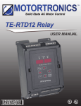
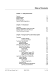
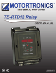
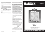
FIGURE 1A – MECHANICAL SPECIFICATIONS (Inches / mm)
for Models KBN2-2250-1, 2201-1 (Pkg. D)
(Remove Top Cover for 50 ºC Rating)
4 x ∅ 0.22
5.6
5.31
135
SEQ
FRQ
FWD
REV
Hz/RPM
VOLT
FUN
AMP
RUN
STOP
DSP
FUN
FWD
REV
RESET
5.91
150
READ
ENTER
0
100
FREQ.SET
3.78
96
NDOP-01
6.38
162
4.21
107
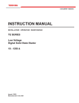
FIGURE 1B – MECHANICAL SPECIFICATIONS (Inches / mm)
for Models KBN2-2202-1, 4301-1, 4302-1 (Pkg. E)
(Remove Top Cover for 50 ºC Rating)
4 x ∅ 0.22
5.6
6.02
153
SEQ
FRQ
Hz/RPM
FWD
REV
VOLT
FUN
AMP
DSP
FUN
RUN
STOP
FWD
REV
RESET
READ
ENTER
0
7.24
184
100
FREQ.SET
5.43
138
6.85
174
NDOP-01
5.87
149
11
Sec. I – Introduction (Cont.)
READ
ENTER
RESET
NDOP-01
DSP
FUN
FWD
REV
AMP
RUN
STOP
VOLT
FUN
4x∅
0.22
5.6
7.28
185
6.85
174
0
FREQ.SET
SEQ
100
FRQ
FWD
REV
Hz/RPM
8.03
204
8.46
215
6.42
163
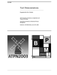
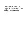
FIGURE 1C – MECHANICAL SPECIFICATIONS (Inches / mm)
for Models KBN2-2203-1, 2305-1, 4303-1, 4501-1 (Pkg. F)
(Remove Top Cover for 50 ºC Rating)
12
Sec. I – Introduction (Cont.)
NDOP-01
RESET
READ
ENTER
FWD
REV
AMP
DSP
FUN
4x∅
0.24
6
7.32
186
7.87
200
100
0
SEQ
FREQ.SET
FRQ
FWD
RUN
STOP
VOLT
FUN
REV
Hz/RPM
11.26
286
11.81
300
7.83
199
FIGURE 1D – MECHANICAL SPECIFICATIONS (Inches / mm)
for Models KBN2-2307-1, 2310-1, 4307-1, 4310-1 (Pkg. G)
(Remove Top Cover for 50 ºC Rating)
13
Sec. I – Introduction (Cont.)
NDOP-01
RESET
READ
ENTER
FWD
REV
AMP
DSP
FUN
4 x ∅ 0.28
7
9.29
236
9.84
250
100
0
SEQ
FREQ.SET
FRQ
FWD
RUN
STOP
VOLT
FUN
REV
Hz/RPM
15.16
385
15.75
400
9.45
240
FIGURE 1E – MECHANICAL SPECIFICATIONS (Inches / mm)
for Models KBN2-2315-1, 2320-1, 2330-1, 4315-1, 4320-1, 4330-1 (Pkg. H)
14
Sec. II – Mounting Inst.
II.
MOUNTING INSTRUCTIONS
It is recommended that the drive be mounted vertically on a flat surface with adequate
ventilation. Leave enough room below the drive to allow for AC line, motor connections,
and other wiring that is required. Care should be taken to avoid extreme hazardous locations
where physical damage can occur. When mounting the drive in an enclosure, the enclosure
must be large enough to allow for proper heat dissipation so that the ambient temperature
does not exceed 50 ºC. See Figures 1A -1E, on pages 11 - 14.
Note: The top cover, on all models thru 10 HP, must be removed to achieve 50 ºC ambient
temperature at full drive rating. Rating with cover installed is 40 ºC. All other models are
rated 50 ºC.
III.
RECONDITIONING THE BUS CAPACITORS
It is recommended that the bus capacitors be reconditioned if this product has been in
storage for over one year. To recondition the capacitors, apply the AC line, with the control
in the Stop Mode, for a minimum of one hour.
IV.
TERMINAL BLOCK TM1 WIRING INSTRUCTIONS (Power Connections)
!
WARNING! Read Safety Warning, on page 6, before using this drive. Disconnect
the main power when making connections to the drive.
For Terminal Block TM1 wiring information, see Table 4, on page 16.
FIGURE 2A – PKG. D, E, F, G
TERMINAL BLOCK TM1 DESIGNATION
Important Application Note – To
L1 L2 L3 P R T1 T2 T3
avoid erratic operation, do not
bundle the AC line and motor
wires with wires from signal following, start/stop contact, or any
other signal wires. Also, do
FIGURE 2B – PKG. H
not bundle motor wires from
TERMINAL BLOCK TM1 DESIGNATION
multiple drives in the same
conduit. Use shielded cables
L1 L2 L3 P1 P N T1 T2 T3
on all signal wiring over 12”
(30 cm). The shield should be
earth grounded on the drive
side only. Wire the drive in
accordance with the National Electrical Code requirements and other local codes that
may apply. See Figures 3A, 3B, and 3c, on pages 16 and 17.
Be sure to properly fuse each AC line input conductor that is not at ground potential.
Do not fuse neutral or grounded conductors. A separate AC line switch or contactor
must be wired as a disconnect so that each ungrounded conductor can be disconnected. For all 3-phase AC line input models, a magnetic contactor with the appropriate current rating is recommended. See Section VI, on page 25.
Note: To access terminals, loosen the captive front panel screw and remove the cover. After
wiring is complete, replace the cover and tighten, but do not over tighten, the screw.
15
Sec. IV – Term. Block TM1 Wiring Inst. (Cont.)
TABLE 4 – TERMINAL BLOCK TM1 WIRING INFORMATION
Pkg.
D
E
F
G
H
Model No.
Part No.
KBN2-2250-1
12000
KBN2-2201-1
12010
KBN2-2202-1
12020
KBN2-4301-1
12100
KBN2-4302-1
12110
KBN2-2203-1
12030
KBN2-2305-1
12040
KBN2-4303-1
12120
KBN2-4305-1
12130
KBN2-2307-1
12050
KBN2-2310-1
12060
KBN2-4307-1
12140
KBN2-4310-1
12150
KBN2-2315-1
12070
KBN2-2320-1
12080
KBN2-2330-1
12090
KBN2-4315-1
12160
KBN2-4320-1
12170
KBN2-4330-1
12180
A. AC Line Connection – Wire
the AC line to Terminals L1,
L2 (for single phase AC line)
or to Terminals L1, L2, L3
(for 3-phase AC line) of
Terminal Block TM1, as
shown in Figures 3A, 3B,
and 3C, on page 17.
Notes: 1. The drive rated
AC line voltage (208/230,
380/460 Volts AC) must
match the actual AC line
input voltage, as described
in Section VIII-C-3, on page
32. 2. If one of the AC line
inputs is a neutral (N), wire
it to Terminal L2.
B. Ground Connection –
Connect the ground wire
(earth) to the ground screw
as shown in Figures 3A, 3B,
and 3C, on page 17.
16
Maximum Wire Size (Cu)
Recommended Tightening Torque
AWG
mm2
in-lbs
kg-cm
16
1.3
8.5
10
14
2.1
8.5
10
10
5.3
15.5
18
10
5.3
15.5
15
6
13.3
22
25
4
21.2
22
25
6
13.3
22
25
FIGURE 3A – PKG. D, E, F
POWER CONNECTIONS WITH 1φ AC LINE INPUT
Chassis
Ground
(Earth)
L1 L2 L3 P
1φ AC Line Input
R T1 T2 T3
Optional
Brake Resistor
3φ AC Induction Motor
FIGURE 3B – PKG. D, E, F, G
POWER CONNECTIONS WITH 3 φ AC LINE INPUT
Chassis
Ground
(Earth)
L1 L2 L3 P
3 φ AC Line Input
R T1 T2 T3
Optional
Brake Resistor
3 φ AC Induction Motor
For single phase AC line connection,
use Terminals L1 and L2.
Sec. IV – Term. Block TM1 Wiring Inst. (Cont.)
FIGURE 3C – PKG. H POWER CONNECTIONS
C. Motor Connection – Wire
the motor to Terminals T1
L1 L2 L3 P1 P N T1 T2 T3
(U), T2 (V),T3 (W) of
Chassis
Terminal Block TM1, as
shown in Figures 3A, 3B,
Jumper
on page 16, and 3C. Motor
+
cable length should not
Optional
Ground
3 φ AC Line Input
3 φ AC Induction Motor
exceed 100 feet (30 m). If
Brake Module
(Earth)
exceeding 100 feet (30 m),
special AC line reactors
may be required, contact our Sales Department.
Note: Be sure the motor rated voltage (208/230, 380/460 Volts AC) matches the control
output voltage.
See Section IV, Important Application Note, on page 15.
D. Optional Brake Resistor Connection – To improve braking, an optional external Brake
Resistor can be connected to Terminals “P” and “R” of Terminal Block TM1, as shown in
Figures 3A and 3B, on page 16. This Brake Resistor allows maximum braking torque. This
option is only available for Models KBN2-2250-1, 2201-1, 2202-1, 2203-1, 2305-1,
2307-1, 2310-1, 4301-1, 4302-1, 4303-1, 4305-1, 4307-1, 4310-1. See Section X-B,
on page 81.
CAUTION! To avoid overheating, do not mount the brake resistor under the drive.
TERMINAL BLOCK TM2 WIRING INSTRUCTIONS (Signal Connections)
The KBN2 contains 15 signal terminals which can be used for various functions. For Terminal
Block TM2 wiring information, see Table 5, on page 18.
Note: If external signal wiring is not used, proceed to Section VI, on page 25.
IMPORTANT! To avoid erratic operation, do not bundle the AC line and motor wires
with wires from signal following, start/stop contact, or any other signal wires. Use
shielded cables on all signal wiring over 12” (30 cm). The shield should be earth
grounded on the drive side only. Wire the drive in accordance with the National
Electrical Code requirements and other local codes that may apply.
FIGURE 4 – TERMINAL BLOCK TM2 DESIGNATION AND
GENERAL CONNECTION DIAGRAM (All Models)
Low
Wiper
RELAY FWD REV COM SP1 SP2 SP3 RES SYN- SYN+ +
FM- FM+
1 2 3 4 5 6 7 8 9 10 11 12 13 14 15
High
V.
- +
Output
Relay
Contact
Fwd
Rev
Multifunction
Input Terminals
Reset
Open
Collector
Output
- +
Main Speed
Potentiometer
Analog
Output
Voltage
17
Sec. V – Term. Block TM2 Wiring Inst. (Cont.)
Application Note – Although this section covers the wiring of Terminal Block TM2, the
respective programming functions are also presented. Function programming is also covered
in Drive Operation, in Section VIII, on page 27. Also see the Programmable Functions
(Detailed), Section IX, starting on page 55.
TABLE 5 – TERMINAL BLOCK TM2 WIRING INFORMATION (All Models)
Maximum Wire Size (Cu)
Description
All Signal Input and Outputs (Terminals 1 - 15)
Recommended Tightening Torque
AWG
mm2
in-lbs
kg-cm
18
0.8
5
6
FIGURE 5A
Notes: 1. Terminal “5” is the “Common” for the
FORWARD/STOP-REVERSE/STOP
Start/Stop circuit and the Multifunction Input Terminals.
CONNECTION (Maintained Contacts)
The maximum allowable load current is 20 mADC. 2.
(F003 Set to “xx00”) (Factory Setting)
All terminals of Terminal Block TM2 are isolated from
the AC line and motor wiring. This eliminates the need for
FWD REV COM
isolated input signals. 3. Function codes are sometimes
3 4 5
represented with one or more “x”. An “x” is used when
the code is used for functions other than the function
Fwd/Stop
presently discussed (example: xx01).
A. External Run/Stop Forward/Reverse Connection –
External control of Run/Stop and Forward/Reverse is
achieved by wiring contacts to Terminals 3, 4, 5, and
6 as shown in Figures 5A - 5D. To program the drive
for external Run/Stop, set Function F010 to “0001”
[External Contacts]. The settings for external
Run/Stop control using F003 are shown in
Table 6, on page 19.
Rev/Stop
FIGURE 5B
RUN/STOP-FORWARD/REVERSE
CONNECTION (Maintained Contacts)
(F003 Set to “xx01”)
FWD REV COM
3 4 5
The drive is factory programmed for Forward/Stop using
Terminal 3 and Reverse/Stop using Terminal 4. To program
Run/Stop
the drive for Run/Stop using Terminal 3 and Forward/
Fwd/Rev
Reverse using Terminal 4, set F003 to “xx01”. For 3-wire
Start/Stop, set Function F003 to “XX10”. See Section
VIII-D-2, on page 33
FIGURE 5D – 3-WIRE START/STOP
for programming
CONNECTION WITH REVERSE
FIGURE 5C
(Momentary Contacts)
information.
3-WIRE START/STOP
WARNING!
The Stop
Contact is never to
be used as a Safety
Disconnect since it
is not fail-safe. Use
only the AC line for
this purpose.
!
18
CONNECTION
(Momentary Contacts)
(F003 Set to “xx10”)
(F003 Set to “xx10”)
(Use a Maintained Contact
for Reverse)
FWD REV COM SP1
3 4 5 6
FWD REV COM
3 4 5
Close to
Reverse
Start
Start
Stop
Stop
Sec. V – Term. Block TM2 Wiring Inst. (Cont.)
TABLE 6 – EXTERNAL RUN/STOP-FORWARD/REVERSE CONTROL [F003]
Contact Configuration
F003 Code Setting*
Forward/Stop-Reverse/Stop (Maintained Contacts)
See Figure 5A, on page 18.
0000
(Factory Setting)
Run/Stop-Forward/Reverse (Maintained Contacts)
See Figure 5B, on page 18.
0001
Contact Status
Term. 3
Term. 4
Open
Open
Closed
Open
Open
Closed
Closed
Closed
Open
Open
Closed
Open
Open
Closed
Closed
Closed
Drive Operation
Stop
Forward
Reverse
Stop
Stop
Forward
Stop
Reverse
*Set F010 [Run/Stop Control] to “0001” [External Contacts].
B. External Frequency Control – Terminals 12, 13, and 14 can be wired in a variety of ways
to control the output frequency of the drive. See Table 7. F011 [Frequency Control Method]
is used to program the drive to control motor frequency with an external signal instead of
the keypad, as described in Section VIII-D-3, F011, on page 34. Function F011 is factory
set to “0000” [Keypad].
Jumper JP1/JP2 is used to set the drive for potentiometer, voltage, or current input signal.
The jumper is factory installed in the “1-2” position of Jumper JP1 for 0 - 5 Volts DC signal input or a speed potentiometer connected to Terminal Block TM2.
TABLE 7 – SIGNAL INPUT, F011, AND JUMPER JP1/JP2 SETTING
Frequency Control Method
F011 Code Setting
JP1 Setting
JP2 Setting
Keypad (Factory Setting)
0000*
1 - 2*
—
Potentiometer on Keypad
0001
1 - 2*
—
0002
1 - 2*
—
0 - 10 VDC Voltage Following
0002
—
2-3
0 - 20 mADC or 4 - 20 mADC Current Following**
0002
2-3
—
Up/Down Frequency Control
using Multifunction Input Terminals
0003
1 - 2*
—
Jumper Position
Remote 5 kΩ (or 10 kΩ) Potentiometer
0 - 5 VDC Voltage Following
*Factory Setting. ** To set the drive for 4 - 20 mADC input, F027 must be set to “0020” (Factory setting is “0000”)
19
Sec. V-B – Term. Block TM2 Wiring Inst. (Cont.)
Application Note – The KBN2 can be programmed to accept a
wide range of voltage or current input signals using Functions
F026 - F029, as described in Section VIII-D-4, on pages 35 - 37.
Location of Jumper JP1/JP2: To access Jumper JP1/JP2,
loosen the captive front panel screw and lift off the cover.
The jumper is located above Terminal Block TM2, as shown
in Figure 6.
FIGURE 7A
REMOTE SPEED
POTENTIOMETER
CONNECTION
JP1
1
2
3
JP2
1
2
3
9
10
11
12
FIGURE 7B
JUMPER JP1 SET FOR
EXTERNAL SPEED
POTENTIOMETER
(FACTORY SETTING)
Low
High
+
FM12 13 14
Wiper
1. Remote Speed Potentiometer
Connection – A 5 kΩ (or 10 kΩ)
remote speed potentiometer can
be connected to Terminal Block
TM2 to control motor speed.
Connect the high side of the
potentiometer to Terminal 12, the
wiper to Terminal 13, and the low
side to Terminal 14, as shown in
Figure 7A. Set F011 [Frequency
Control Method] to “0002” and
be sure the jumper is installed in
the “1-2” position of Jumper JP1
(factory setting), as shown in
Figure 7B. (See Section VIII-D-3,
on page 34.
FIGURE 6 – TYPICAL
LOCATION OF
JUMPER JP1/JP2
Main Speed
Potentiometer
FIGURE 8A
FIGURE 8B
JP2 SET FOR 0 - 10 VDC
VOLTAGE FOLLOWING
2. Voltage Following Connection –
VOLTAGE FOLLOWING
CONNECTION
A 0 - 5 or 0 -10 Volt DC analog
SIGNAL OUTPUT
signal input can be connected to
Terminal Block TM2 to control
+
FMmotor speed. Connect the signal
12 13 14
voltage (+) to Terminal 13 and the
common (-) to Terminal 14, as
+
shown in Figure 8A. Set F011
0 - 10 VDC V
[Frequency Control Method] to
“0002” [Analog Signal]. For 0 - 5
Volt DC analog signal voltage, be
FIGURE 8C – VOLTAGE
sure the jumper is installed in the “1-2” position (factory
FOLLOWING CONNECTION
setting) of Jumper JP1. For 0 - 10 Volt DC analog sigWITH SERIES RESISTOR
nal voltage, install the jumper in the “2-3” position of
Jumper JP2, as shown in Figure 8B.
Notes: 1. F011 [Frequency Control Method] is factory
set to “0000” [Keypad]. 2. Functions F026, F027, and
F028 can be used to rescale the drive for other input
signals. 3. Input impedance of Terminal 13 is 20 kΩ.
+
FM12 13 14
+
Voltage
Source
V
-
20
R IN
Sec. V-B-2 – Term. Block TM2 Wiring Inst. (Cont.)
Application Note – If the input signal is greater than the drive setting, a resistor must
be installed in series with the signal input, as shown in Figure 8C, on page 20.
Calculate the series resistor (RIN) using the following formula. Be sure the drive is set
for 0 - 5 VDC signal input (F011 set to “0002” and the jumper is installed in the “1-2”
position of Jumper JP1). (See Table 7, on page 19.)
RIN = (VIN X 33kΩ) -165kΩ
Example – If the signal input is 20 Volts DC, RIN = (20V X 33kΩ) - 165kΩ = 495kΩ.
Use the next higher resistor
FIGURE 9B
FIGURE 9A
value, which is 500kΩ
CURRENT FOLLOWING
CONNECTION
3. Current Following Connection
A 0-20 mA DC or 4-20 mA DC
+
analog signal input can be
12
connected to Terminal Block
TB2 to control motor speed.
Connect the signal current (+)
0 - 20 mADC
or
to Terminal 13 and the common
4 - 20 mADC
(-) to Terminal 14, as shown in
Figure 9A. Install the jumper in
the “2-3” position of Jumper JP1, as shown
in Figure 9B. Function F011 must be set to
“0002”. For a 4 - 20 mADC signal,
F027 must be set to “0020”
(factory setting is “0000”).
4. Multifunction Input Terminals Connection
The Multifunction Input Terminals “6”,
“7”, and “8” can be programmed
for a variety of functions. See
Programming Functions (Detailed),
Section IX, F056 - F058, on pages
65 and 66. Several of the programmable
functions can be used for External
Frequency Control. These include
Up/Down Frequency Control, Preset
Speed Operation (7 frequency settings),
and Jog.
The terminals are activated by closing
or opening (depending on the settings
of Functions F056, F057, and F058) a
contact referenced to Terminal “5” (COM).
See Figures 10A, 10B, and 10C, on page 22.
JUMPER JP1 SET FOR
CURRENT FOLLOWING
SIGNAL INPUT
FM13 14
+
-
FIGURE 10A – MULTIFUNCTION
INPUT TERMINALS CONNECTION
WITH NORMALLY OPEN CONTACTS
(CLOSE TO ACTIVATE)
COM SP1 SP2 SP3
5 6 7 8
FIGURE 10B – MULTIFUNCTION
INPUT TERMINALS CONNECTION
WITH NORMALLY CLOSED CONTACTS
(OPEN TO ACTIVATE)
COM SP1 SP2 SP3
5 6 7 8
21
Sec. V-B-4-a – Term. Block TM2 Wiring Inst. (Cont.)
FIGURE 10C – MULTIFUNCTION
INPUT TERMINALS CONNECTION
WITH OPEN COLLECTOR
a. External Up/Down Frequency Control –
External contacts can be used to simulate
the ▲ and ▼ keys on the digital keypad.
Any two of Terminals 6, 7, and 8 can be
programmed for Up/Down Frequency Control
using Functions F056, F057 (or F058). See
figures 11A, 11B, and 11C.
COM SP1 SP2 SP3
5 6 7 8
To program Terminal 6 for Up Control using
normally open contacts, set Function F056 to
“0012”. (To program Terminal 6 for Up Control
using normally closed contacts, set Function
F056 to “0028”.) The incremental rate of
change of the Up Control for frequency setting, using external contacts, is proportional to the Acceleration Time #1 setting [F001].
To program Terminal 7 for Down Control using normally open contacts, set Function
F057 to “0013”. (To program Terminal 7 for Down Control using normally closed
contacts, set Function F057 to “0029”.) The incremental rate of change of the
Down Control for frequency setting, using external contacts, is proportional to the
Deceleration Time # 1 setting [F002].
Note: For Up/Down Frequency Control using the Multifunction Input Terminals,
Function F011 must be set to “0003” [Up/Down Frequency Control].
TABLE 8 – SETTINGS FOR EXTERNAL UP/DOWN FREQUENCY CONTROL
Function
Number
Function Description
Code Description
F011
Frequency Control Method
0003 (Factory Setting is “0000”)
Up/Down Frequency Control
F056
Multifunction Input Terminal 6 (SP1)
0012 (Factory Setting is “0000”)
Up Command
F057
Multifunction Input Terminal 7 (SP2)
0013 (Factory Setting is “0001”)
Down Command
FIGURE 11A – UP/DOWN
FREQUENCY CONTROL
CONNECTION
WITH NORMALLY
OPEN CONTACTS
COM SP1 SP2
5 6 7
Up
22
Code
FIGURE 11B – UP/DOWN
FREQUENCY CONTROL
CONNECTION
WITH NORMALLY
CLOSED CONTACTS
COM SP1 SP2
5 6 7
COM SP1 SP2
5 6 7
Down
Up
FIGURE 11C – UP/DOWN
FREQUENCY CONTROL
CONNECTION WITH
OPEN COLLECTOR
Down
Up
Down
Sec. V-B-4-b – Term. Block TM2 Wiring Inst. (Cont.)
b. Preset Speed Operation – Many applications require preset speed operation. The
drive is capable of providing (7) preset speeds using a combination of Terminals “6”,
“7”, “8”. See Table 9.
Terminal “6” has been factory programmed for Preset Speed # 1 using Function F056
(factory set to “0000”). Terminal “7” has been factory programmed for Preset Speed
# 2 using Function F057 (factory set to “0001”). Terminal “8” has been factory programmed for Preset Speed # 4 (factory set to “0002”). To obtain Preset Speed # 3,
Terminals “6” (SP1) and “7” (SP2) must be connected together. Normally open or normally closed contacts may be used, as shown in Figures 10A and 10B, on page 21.
Functions F017 through F023 are used to program the frequency for Preset Speed
# 1 through Preset Speed # 7. See Section IX, F017 - F023, on page 58.
TABLE 9 – SELECTING PRESET SPEEDS USING MULTIFUNCTION
INPUT TERMINALS 6, 7, 8
Preset Speed
Factory Setting
Multifunction Input Terminal*
Function Number
to Set Frequency
Term. 6 (SP1)
Term. 7 (SP2)
Term. 8 (SP3)
1
5.0 Hz
F017
Activated
—
—
2
10.00 Hz
F018
—
Activated
—
3
20.00 Hz
F019
Activated
Activated
—
4
30.00 Hz
F020
—
—
Activated
5
40.00 Hz
F021
Activated
—
Activated
6
50.00 Hz
F022
—
Activated
Activated
7
60.00 Hz
F023
Activated
Activated
Activated
Keypad (Factory Setting)
5.00 Hz
F025
—
—
—
*”Activated” means that the terminal has been selected. If the terminal is programmed for normally open contacts,
closing the contact will activate the terminal. If the terminal is programmed for normally closed contacts, opening the
contact will activate the terminal.
Note: When switching two or three contacts together, the operation time must be within 10 mS.
Notes: 1. Using the programming functions, the drive is capable of assigning a separate “timed” function (Process Timer) for each of the Preset Speeds which are
controlled by Multifunction Input Terminals “6”, “7”, and “8”. See Section V-B-4, on
page 21. In addition, the timed Preset Speeds can be programmed in a linked
sequence so that one timed Preset Speed will automatically follow the next.
(example: Preset Speed # 1 ➤ Preset Speed # 2 ➤ ..... ➤ Preset Speed # 7).
If F084 [Process Timer Operation Mode] is set to “0101”, the Process Timer will
repeat continuously through all the Preset Speeds until the drive is stopped. 2. If the
drive has been programmed for Process Timers, the Preset Speeds can no longer
be set for continuous operation. 3. When Process Timers are enabled, a specific
time greater than zero must be assigned to each preset in order for the Preset
Speed to operate. 4. If “000.0” time is programmed in ALL Process Timers and
Process Timer Operation is attempted, the drive will trip and the error code “CPF”
will flash on the display. Press the </RESET key to reset the drive. 5. A run command and a forward or reverse direction must be selected for Preset
Speeds to operate.
23
Sec. V-B-4-c – Term. Block TM2 Wiring Inst. (Cont.)
c. Jog Speed Operation – The drive provides selection for a “jog” speed. To select
the jog frequency which is programmed in Function F024 (factory setting is 2.00
Hz), wire normally open or normally closed contacts to one of the Multifunction
Input Terminals. To program one of the Multifunction Input Terminals for Jog using
normally open contacts, set Function F056, F057, or F058 to “0003”. To program
one of the Multifunction Input Terminals for Jog using normally closed contacts, set
Function F056, F057, or F058 to “0019”
C. Multifunction Output Relay Connection – Normally open
(NO) or normally closed (NC) relay contacts are provided at
Terminals 1 and 2 of Terminal Block TM2. These contacts
change state depending on the setting of Functions F097
and F098, as described in Section IX, on pages 72 and 73.
F097 and F098 are both factory set to “0000” [Output Relay
is Not Operational]. See Figure 12.
Note: The Output Relay contacts are rated 1 Amp at 30 Volts
DC or 250 Volts AC.
FIGURE 12
MULTIFUNCTION OUTPUT
RELAY CONNECTION
RELAY
1 2
Output Relay Contact
FIGURE 13
D. Multifunction Analog Output Connection – Terminals 14 and
MULTIFUNCTION ANALOG
15, of Terminal Block TM2, provide an isolated 0 - 10 Volt DC
OUTPUT CONNECTION
analog signal output proportional to the function for which it is
programmed, as described in Section IX, F046, on page 63.
F046 [Multifunction Analog Output] is factory set to “0000”
+
FM- FM+
12 13 14 15
[Output Frequency] which will provide an isolated 0 - 10 VDC
voltage proportional to the drive output frequency. See Figure
13. Other functions include “0001” [Set Frequency], “0002”
- +
[Drive Output Voltage], and “0003 [Bus Voltage]. The Analog
Analog Output Voltage
Output Voltage can be rescaled using Function F045. See
Section IX, F045, on page 62. (Maximum allowable load current is 1 mADC)
E. Multifunction Open Collector Output Connection
FIGURE 14
MULTIFUNCTION OPEN
– An isolated open collector output is provided at
COLLECTOR OUTPUT CONNECTION
Terminals 10 and 11, of Terminal Block TM2, which
will change state when the drive operates as programmed in F061 [Multifunction Output Terminals
SYN– SYN+
10,11]. F061 is factory set to “0000” [Run], which
35 VDC - 50 mADC
10 11
will cause the Multifunction Open Collector Output
Clamping Diode (Required)
Terminal to change state when the drive is in Run
Mode. A typical application for Open Collector
Relay
Output is shown in Figure 14. Other functions
include “0001” [Frequency Reached (Target
- +
35 VDC (Max.)
Frequency)], “0002” [Set Frequency (F008/F009)],
“0003” [Frequency Detection (> F008) - Frequency
Reached], “0004” [Frequency Detection (< F008) - Frequency Reached], “0005” [Overload
Detection]. The Open Collector Output circuit is rated 35 Volts DC at 50 mA DC.
24
Sec. V-F – Term. Block TM2 Wiring Inst. (Cont.)
FIGURE 15A
RESET CONNECTION
F. Reset Connection – A normally open momentary contact can be connected to
Terminals 5 and 9, of
Terminal Block TM2, to
reset the drive after a fault
has cleared, as shown in
Figure 15. (Also see Section
IX, F016, on page 57).
COM SP1 SP2 SP3 RES
5 6 7 8 9
FIGURE 15B
RESET CONNECTION
WITH OPEN COLLECTOR
COM SP1 SP2 SP3 RES
5 6 7 8 9
G. RS-232 or RS-485 Communication Cable Connection –
When installing the optional RS-232 or RS-485
Communication Cable, remove the jumper that is installed on CON12. CON12 is located
above Terminal Block TM2. Be sure the factory installed jumper is in the “1-2” position of
CON12, if not using RS-232 or RS-485 communications. RS-232 or RS-485 is used to
progam the drive using a PC. The Download Module (DLM) can also be used to program
the drive. See Section X-E, on page 79.
VI.
AC LINE FUSING
This drive does not contain AC line input fuses. Most electrical codes require that each
ungrounded conductor contain circuit protection. Install a fuse or circuit breaker in series with
each ungrounded conductor. For all 3-phase AC line input models, a magnetic contactor with
the appropriate current rating is recommended. Do not fuse neutral or grounded conductors.
See Table 10. Check all electrical codes that apply to the application. Do not install a fuse or
circuit breaker in series with motor leads.
TABLE 10 – RECOMMENDED FUSE, CIRCUIT BREAKER, OR MAGNETIC CONTACTOR RATING
Model
Rating (Amps AC)
Model
KBN2-2250-1
10, 5*
KBN2-4301-1
5
KBN2-2201-1
15, 10*
KBN2-4302-1
10
KBN2-2202-1
20, 10*
KBN2-4303-1
15
KBN2-2203-1
30, 15*
KBN2-4305-1
20
KBN2-2305-1
30
KBN2-4307-1
40
KBN2-2307-1
60
KBN2-4310-1
40
KBN2-2310-1
60
KBN2-4315-1
70
KBN2-2315-1
100
KBN2-4320-1
70
KBN2-2320-1
100
KBN2-4330-1
100
KBN2-2330-1
150
Rating (Amps AC)
* Rating is given for 1 φ , 3 φ AC line input.
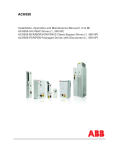
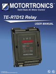
VII. RECOMMENDED HIGH VOLTAGE DIELECTRIC WITHSTAND TESTING (Hi-Pot)
Testing agencies such as UL, CSA, etc., usually require that the equipment undergo a hi-pot
test. In order to prevent catastrophic damage to the drive, which has been installed in the
equipment, it is recommended that the following procedure be followed. A typical hi-pot test
setup is shown in Figure 16, on page 26. All drives have been factory hi-pot tested in accordance with UL requirements.
Note: When performing the hi-pot test, disconnect the AC power.
25
26
RESET
H. V.
Connect Hi-Pot to
All AC Line Inputs
AC Line Input
TEST
10mA
RETURN
0mA
LEAKAGE
2
ZERO
VOLTAGE
MAX
AC KILOVOLTS
1
3
Chassis
T3
T2
T1
R
P
L3
L2
L1
Machine or Equipment Frame
L2
L1
Auxiliary Equipment
Connect All TM1 Terminals Together
(Main Power Disconnected)
0
High Voltage Dielectric Withstand Tester (Hi-Pot Tester)
Chassis
Adjustable Frequency Drive
Motor Wires
Frame
Sec. VIII – Recommended High Voltage Dielectric Withstand Testing (Cont.)
FIGURE 16 – HI-POT SETUP
Sec. VIII – Recommended High Voltage Dielectric Withstand Testing (Cont.)
CAUTION! To avoid damage to the drive, do not connect any terminals of Terminal Block
TM2 to the hi-pot tester.
A. Connect all equipment AC power input lines together and connect them to the H. V. lead
of the hi-pot tester. Connect the RETURN lead of the hi-pot tester to the frame on which
the control and other auxiliary equipment are mounted.
B. The hi-pot tester must have an automatic ramp-up to the test voltage and an automatic
ramp-down to zero voltage.
Note: If the hi-pot tester does not have automatic ramping, then the hi-pot output must
be manually increased to the test voltage and then manually reduced to zero. This procedure must be followed for each machine to be tested. A suggested hi-pot tester is
Slaughter Model 2550.
!
CAUTION! Instantaneously applying the hi-pot voltage will cause irreversible
damage to the drive.
VIII. DRIVE OPERATION
Before operating this drive, read the following instructions on Digital Keypad operation and programming
functions. See Figure 17, for the digital keypad layout.
The display can indicate various functions of the drive:
set frequency, motor RPM, output current and voltage,
custom units, function numbers, function codes or values, and fault codes.
FIGURE 17 – DIGITAL
KEYPAD LAYOUT
If an error message appears while programming the
drive, see Table 22, on pages 74 - 76.
A. Digital Keypad Description – The digital keypad has
7 keys which are used to program drive functions and
control various features, as described below. Eight
LEDs are provided to indicate the drive’s operational
status. A potentiometer is also provided on the keypad to set drive frequency. See Figure 17. Note: To avoid damage, never operate the
keypad with a screwdriver or other sharp-ended tool.
Run/Stop Key – Starts or stops the drive. If the drive is stopped, press the
RUN/STOP key to start the drive. F010 must be set to “0000” (factory
setting). If the drive is running, press the RUN/STOP key to stop the drive.
Forward/Reverse Key – Changes motor direction. If the drive is set to run
the motor in the forward direction, press the FWD/REV key change motor
direction to reverse. The FWD LED will turn off, and the REV LED will illuminate. If the drive is set to run the motor in the reverse direction, press the FWD/REV key
to change motor to forward. The REV LED will turn off, and the FWD LED will illuminate.
F010 must be set to “0000” (factory setting).
27
Sec. VIII-A – Drive Operation (Cont.)
Up Key – Increases output frequency, increases set frequency, increases to
the next higher function number, or changes the function’s value or code
setting. If the drive is running, press the ▲ key to increase the output frequency. If the drive is stopped, press the ▲ key to increase the set frequency. If a function
number is displayed, press the ▲ key to increase the function displayed to the next higher
function number. If a function value or code is displayed, press the ▲ key to increase the
function’s value or code setting.
Down Key – Decreases output frequency, decreases set frequency, decreases to the next lower function number, or changes the function’s value or
code setting. If the drive is running, press the ▼ key to decrease the output
frequency. If the drive is stopped, press the ▼ key to decrease the set frequency. If a
function number is displayed, press the ▼ key to decrease the function displayed to the
next lower function number. If a function value or code is displayed, press the ▼ key to
decrease the function value or code setting.
Display/Function Key – Changes the display between Display Mode and
Function Mode. If DSP/FUN is pressed while frequency is displayed, the
display will indicate the previously entered function number. If DSP/FUN is
pressed while a function number is displayed, the display will change to display output
frequency. Note: The DSP/FUN key can be used to display Motor RPM, Motor Voltage,
Motor Current, Drive Bus Voltage, and Custom Units, depending on the setting of
Functions F047 and F051.
Shift/Reset Key – Resets the drive after a fault has cleared or moves the
display digit to be set one position to the left. The display digit will “flash”,
indicating it can be changed with the ▲ or ▼ keys.
Read/Enter Key – Displays or enters a function value or code setting. If the
desired function number is displayed, press the READ/ENTER key to display
the function’s value or code. If the desired value or code is displayed, press
the READ/ENTER key to program the function to the new value or code.
Keypad Potentiometer – Sets motor frequency. Operation is from 0 - 100%
of the range set by the Lower and Upper Output Frequency Limits. To
program the drive for Keypad Potentiometer Operation, set Function
F011 to “0001”.
4-Digit LED Display – When power is applied to the drive, the
4-digit LED display will flash the drive AC line voltage setting (Volts
AC) programmed in F030 four times and then flash the set frequency speed (factory setting is “05.00”). When the drive is in “run”, the output frequency is
displayed. When the drive is stopped with the keypad, the set frequency is displayed.
28
Sec. VIII-A – Drive Operation (Cont.)
LED Status Indicators – The drive is designed with 8 LEDs mounted on the digital keypad to display the drive’s operational status, as described below. When power is applied
to the drive (in factory setting), the “VOLT”, and “FWD” LEDs will illuminate on the display
and the POWER LED, (located on the drive PC board, to the right of Terminal Block TM1)
will also illuminate.
TABLE 11 – LED STATUS INDICATORS
When the FUN LED is illuminated, the display shows a Function Number and the drive
is in Program Mode.
When the FWD LED is illuminated, the drive is set for Forward Direction.
When the Hz/RPM LED is illuminated, the display shows Frequency (in Hz) or RPM.
When the REV LED is illuminated, the drive is set for Reverse Direction.
When the SEQ LED is illuminated, the drive is set for External Run/Stop (F010 set
to “0001”).
When the VOLT LED is illuminated, the display shows Motor voltage (Volts AC)
[F047 = xxx1] or bus voltage (Volts DC) [FO47 = xx1x].
When the FRQ LED is illuminated, the drive is set for External Frequency Control or
Keypad Potentiometer Control.
When the AMP LED is illuminated, the display shows Motor current (Amps AC)
[F047 = x1xx].
B. Digital Keypad Operation – Examples of basic keypad operation are described below.
1. Setting Drive Output Frequency Using the Keypad – The drive is factory set to run
at 5.00 Hz when the drive is in the Run Mode. (Press the RUN/STOP Key to start or
stop the drive.)
a. To change the Set Frequency (drive in Stop Mode):
1. Press the </RESET key to move the setable digit to the left and the ▲ or ▼ key
until the desired frequency is displayed. Note: The setable digit will flash.
2. Press the RUN/STOP key to run the drive at the new Set Frequency.
Note: Figure 18, on page 30, is a flow chart which illustrates the sequence to change
and program the Set Frequency from 5.00 Hz to 43.21 Hz using the keypad.
b. To change the Run Frequency (drive in Run Mode):
1. Press the </RESET key to move the setable digit to the left and the ▲ or ▼ key
until the desired frequency is displayed. Note: The setable digit will flash.
2. Press the READ/ENTER key to run the drive at the new Set Frequency.
2. Programming the Drive – The drive contains many functions that can be programmed
for specific application. A summary list of all programmable functions is provided in
Table 17, beginning on page 46.
29
Sec. VIII-B-2 – Drive Operation (Cont.)
FIGURE 18 – FLOW CHART TO CHANGE SET FREQUENCY – Drive in STOP Mode
Power On
RESET
Line Voltage Setting
Flashes 4 Times
Set Frequency
Flashes
Press 1 Time
Display Flashes
Press 1 Time
to Move
Changeable Digit
Changeable Digit
Flashes
for 5 Seconds
RESET
Press 2 Times
Press 2 Times
to Move
Changeable Digit
Display Flashes
Changeable Digit
Flashes for
5 Seconds
Press 2 Times
Display Flashes
READ
ENTER
RESET
Press 3 Times
to Move
Changeable Digit
Changeable Digit
Press 4 Times
Display Flashes
RUN
STOP
Press to Enter New Set Frequency
the New Setting
is Displayed
(F025 Automatically
Sets to "43.21")
Press To Run
the Drive
FIGURE 19 – FLOW CHART TO PROGRAM F001 (ACCELERATION TIME # 1)
Power On
DSP
FUN
Line Voltage Setting
Flashes 4 Times
Press to
Change Display
Set Frequency
Flashes
READ
ENTER
Acceleration
Time # 1
Function Number
is Displayed
Function Number
Display
Press 1 Time
to Change
Function Number
RESET
Press to Display
Acceleration
Time # 1
Setting
Acceleration
Time # 1
is Displayed
Press 3 Times
to Move
Changeable Digit
Changeable Digit
Flashes
READ
ENTER
RESET
Changeable Digit
Flashes
Press 3 Times
to Move
Changeable Digit
Changeable
Digit Flashes
Press 1 Time
DSP
FUN
Momentarily
Displayed
which Confirms
New Setting
30
Press 5 Times
Acceleration
Time # 1
Function Number
is Displayed
Press to
Display
Set Frequency
Set Frequency
Flashes
New Setting
is Displayed
Press to Enter
the New Setting
Sec. VIII-B-2 – Drive Operation (Cont.)
Acceleration Time # 1 [F001] – Sets the acceleration time (seconds) of the drive.
F001 can be changed while the drive is in Stop Mode or Run Mode.
Example – Figure 19, on page 30, illustrates the sequence to program F001 for a 500
second acceleration time.
To change the setting of F001:
a. Press the DSP/FUN key to display Function Number.
b. Press the </RESET key to move the setable digit one position to the left and the ▲
or ▼ key until “F001” is displayed. Note: The setable digit will flash.
c. Press the READ/ENTER key. “010.0” seconds will be displayed (factory setting).
d. Press the </RESET key to move the setable digit one position to the left and the ▲ or
▼ key until the desired acceleration time is displayed. Note: The setable digit will flash.
The programmable range is 0.1 - 3600 seconds. (Note: “000.0” cannot be set.)
e. Press the READ/ENTER key to “enter” the new acceleration time. “End” will be
momentarily displayed, which confirms the new acceleration time setting. “F001”
will be displayed.
f. Press the DSP/FUN key to return to the frequency display or press the ▲ or ▼ key
to change to another function number.
C. Important Programming Functions – All drive functions have been factory programmed,
as shown in Table 17, on page 46. Detailed descriptions of all programmable functions are
given in Section IX, on page 53.
Function codes are sometimes represented with one or more “x”. An “x” is used
when the code is used for functions other than the function presently discussed
(example: xx01).
1. Motor Current Rating [F070] – In order for the Motor Overload Protection Feature
to be effective, Function F070 must be set to the motor nameplate current rating
(Amps AC) if the actual motor current differs nominally from the factory setting.
Note: For the factory default setting for motor current, see Table 20, on page 68.
To enter the motor nameplate current rating into F070:
a. The drive must be in Stop Mode (press the RUN/STOP key).
b. Press the DSP/FUN key to display Function Number.
c. Press the </RESET key to move the setable digit one position to the left and the ▲
or ▼ key until “F070” is displayed. Note: The setable digit will flash.
d. Press the READ/ENTER key. The factory default setting of Motor Current Rating will
be displayed. See Table 20, on page 68.
e. Press the </RESET key to move the setable digit one position to the left and the ▲
or ▼ key until the actual motor nameplate current rating is displayed. Note: The
setable digit will flash.
31
Sec. VIII-C-1 – Drive Operation (Cont.)
f. Press the READ/ENTER key to “enter” the new Motor Current Rating. “End” will be
momentarily displayed, which confirms the new Motor Current Rating setting.
“F070” will be displayed.
g. Press the DSP/FUN key to return to the frequency display or press the ▲ or ▼ key
to change to another function number.
2. 60 Hz, 50 Hz Motor Operation (Volts/Hz Pattern) [F005] – The drive has been factory programmed for 60 Hz motors used in Constant Torque applications (F005 is factory
set to “0009”). To convert to 50 Hz motors used on constant torque applications, set
F005 to “0000”, as described below.
a. The drive must be in Stop Mode (press the RUN/STOP key).
b. Press the DSP/FUN key to display Function Number.
c. Press the ▲ or ▼ key until “F005” is displayed. Note: The setable digit will flash.
Note: The </RESET key may also have to be used.
d. Press the READ/ENTER key. “0009” will be displayed (factory setting).
e. Press the ▼ key nine times. “0000” will be displayed.
f. Press the READ/ENTER key to “enter” the new code. “End” will be momentarily displayed, which confirms the new code setting (“0000”). Then “F005” will be displayed.
g. Press the DSP/FUN key to return to the frequency display or press the ▲ or ▼ key to
change to another function number.
Note: If the application requires full motor torque over a wide speed range, it is recommended that an Inverter Duty or TENV Motor be used. To achieve full torque rating, the
Electronic Motor Overload Protection (Function F069) should be set to “xx1x”. See
Section IX, Function F069, on page 68.
3. AC Line Input Voltage [F030] – Function F030 is used to set the drive to the nominal
AC line input voltage. F030 is factory set to “220.0” for 208/230 Volt AC line input
models and “460.0” for 380/460 Volt AC line input models.
a. 208/230 Volt AC Input Models – Factory set to F030 = “220.0” which will operate
with an AC line input voltage of 208 to 230 Volts AC. If the AC line input voltage is
outside the range of 208 to 230 Volts AC, use F030 to set the nominal input voltage.
b. 380/460 Volt AC Input Models – Factory set to F030 = “460.0” which will operate
with an AC line input voltage of 440 to 470 Volts AC. If the actual AC line input
voltage is outside the range of 440 to 470 Volts AC, use F030 to set the nominal
input voltage.
Example – If the AC line input voltage for a 460 Volt AC model is actually 380 Volts
AC, change the setting of F030 as follows.
1. Press the DSP/FUN key to display Function Number.
2. Press the </RESET key to move the setable digit one position to the left and the
▲ or ▼ key until “F030” is displayed. Note: The setable digit will flash.
32
Sec. VIII-C-3-b – Drive Operation (Cont.)
3. Press the READ/ENTER key. “460.0” will be displayed (factory setting).
4. Press the </RESET key two times and press the ▲ key two times. “480.0” will
be displayed.
5. Press the </RESET key one time and press the ▼ key one time. “380.0” will be
displayed.
6. Press the READ/ENTER key to “enter” the actual AC line input voltage. “End” will
be momentarily displayed, which confirms the new actual AC line input voltage.
“F030” will be displayed.
7. Press the DSP/FUN key to return to the frequency display or press the ▲ or ▼
key to change to another function number.
D. Other Useful Programming – Other programming functions, such as External Control
of Run/Stop and Forward/Reverse, External Control of Motor Frequency, Manual
and Auto Restart, Load Regulation and Torque Boost, and Display Modes are
described below.
1. External Run/Stop-Forward/Reverse Control [F010] – Changes the Run, Stop,
and Reverse commands from the keypad to external contacts, as described in
Section V-A, on page 18. F010 is factory set to “0000” to Run and Stop the
drive using the keypad.
!
WARNING! The Stop Contact is never to be used as a Safety Disconnect since it
is not fail-safe. Use only the AC line for this purpose.
To change the Run/Stop-Forward/Reverse Control from Keypad to External Contacts:
a. The drive must be in Stop Mode (press the RUN/STOP key).
b. Press the DSP/FUN key to display Function Number.
c. Press the </RESET key to move the setable digit one position to the left and the ▲
or ▼ key until “F010” is displayed. Note: The setable digit will flash.
d. Press the READ/ENTER key. “0000” will be displayed (factory setting).
e. Press the ▲ key one time. “0001” will be displayed.
f. Press the READ/ENTER key to “enter” the new code. “End” will be momentarily displayed, which confirms the new code setting. “F010”will be displayed.
g. Press DSP/FUN key to return to the frequency display or press the ▲ or ▼ key to
change to another function number.
Notes: 1. In order for the reverse function to operate, F003 must be set to “x0xx”
[Enable Reverse Run] (factory setting). 2. The STOP key on the keypad is always
operative, even if F010 is set to “0001” [External Contacts].
2. External Forward-Stop-Reverse Control [F003] – Sets the drive for either
Forward/Stop-Reverse/Stop (factory setting), Run/Stop-Forward/Reverse, or 3-Wire
Start/Stop, as described in Section IX, Function F003, on page 54.
!
WARNING! The Stop Contact is never to be used as a Safety Disconnect since
it is not fail-safe. Use only the AC line for this purpose.
33
Sec. VIII-D-2 – Drive Operation (Cont.)
a. The drive must be in Stop Mode (press the RUN/STOP key).
b. Press the DSP/FUN key to display Function Number.
c. Press the </RESET Key to move the setable digit one position to the left and the ▲
or ▼ key until “F003” is displayed. Note: The setable digit will flash.
d. Press the READ/ENTER key. “0000” will be displayed (factory setting).
e. Press the </RESET key to move the setable digit one position to the left and the ▲
or ▼ key until the desired code setting is displayed. Note: The setable digit will
flash. The programmable codes for F003 are as follows.
F003 = xx00: Forward/Stop-Reverse/Stop (Factory Setting)
xx01: Run/Stop-Forward/Reverse
xx10: 3-Wire Start/Stop Control
f. Press the READ/ENTER Key to “enter” the desired External Forward-Stop-Reverse
control Code (“0000”, “0001”, “0010”).
g. Press the DSP/FUN key to return to the frequency display or press the ▲ or ▼ key
to change to another function number.
Note: F003 is also used to enable or disable reverse operation. Additionally, when
Multifunction Input Terminals are programmed for Up/Down Frequency Control, F003
is used to display either the “Set Frequency” (RPM or Custom Units) or “zero” when
the drive is in “STOP”. (See Section IX, Function F003, on page 54.)
3. Frequency Control Method [F011] – Set the drive for either keypad, potentiometer on
keypad, external potentiometer, voltage following, or current following frequency control, as described in Section V-B, on page 19 . F011 is factory set to “0000” to control
output frequency with the keypad. To change the Frequency Control Method:
a. The drive must be in Stop Mode (press the RUN/STOP key).
b. Press the DSP/FUN key to display Function Number (Fxxx).
c. Press the </RESET Key to move the setable digit one position to the left and the ▲
or ▼ key until “F011” is displayed. Note: The setable digit will flash.
d. Press the READ/ENTER key. The function code setting will be displayed.
Factory setting is “0000”.
e. Press the </RESET key to move the setable digit one position to the left and the ▲
or ▼ key until the desired code setting is displayed. The programmable codes for
F011 are as follows.
F011 = 0000:
0001:
0002:
0003:
Keypad (Factory Setting)
Potentiometer on Keypad
External Analog Signal Input or Remote Potentiometer
Up/Down Frequency Control (See Section V-B-4-a, on page 22)
f. Press the READ/ENTER key to “enter” the Frequency Control Method. “End” will be
momentarily displayed, which confirms the Frequency Control Method setting.
“F011” will be displayed.
34
Sec. VIII-D-3 – Drive Operation (Cont.)
g. Press the DSP/FUN key to return to the frequency display or press the ▲ or ▼ key
to change to another function number.
Note: A jumper must be installed in the proper position of Jumper JP1/JP2 to set the
drive for voltage or current signal input, as described in Section V-B-2 and V-B-3, on
pages 20 and 21. See Section VIII-D-4.
4. Analog Signal Input Scaling [F026, F027, F028, F029] – The drive can be set for standard signal inputs (0 - 5 VDC, 0 - 10 VDC, 0 - 20 mADC, and 4 - 20 mADC). Use
Function F011 and select the proper position of Jumper JP1/JP2 to set the drive for the
closest standard input signal to the actual signal used. See Table 12 and Figure 20.
TABLE 12 – SIGNAL INPUT AND JUMPER JP1/JP2 SETTING (F011 SET TO “0002”)
Drive Input Signal Range
JP1 Setting
JP2 Setting
0 - 5 VDC
1-2
(Factory Setting)
—
0 - 10 VDC
—
2-3
0 - 20 mADC or 4 - 20 mADC*
2-3
—
Jumper Position
* To set the drive for 4 - 20 mADC input, F027 must be set to “0020” (Factory setting is “0000”).
FIGURE 20 – INPUT SIGNAL SCALING
a. Frequency Offset [F026]
– This function sets the
drive output frequency
lower limit at the minimum
input signal.
Notes: 1. F026 is equivalent to F007 [Output
Frequency Lower Limit].
2. F026 is factory set to
“00.00” (0.00 Hz).
Drive Output Frequency (%)
F006
F026
Example – If the drive has
been set for a 4 - 20
mADC input signal and the
desired drive minimum frequency is 30 - 60 Hz, set
F026 to “0030” (30 Hz).
100
0
0
Analog Input Signal (%)
100
F027
F028
b. Analog Input Signal Reference Ratio [F027] – This function sets the range of the
input signal and is defined by the following formula.
F027 = (Minimum Input Signal
÷ Maximum Input Signal) X 100
35
Sec. VIII-D-4-b – Drive Operation (Cont.)
Notes: 1. F011 is factory set
to “0000”. 2. The jumper is
factory installed in the “1-2”
position of Jumper JP1. 3.
F027 is factory set to
“000.0” (0.0 %).
c. Analog Input Scaling
Reference Ratio [F028] –
This function sets the scaling
of the maximum value of the
actual input signal as compared to the drive input signal setting and is defined by
the following formula.
F028 = (Supplied Input
Signal Upper Limit ÷ Drive
Input Signal Setting) X 100
100
Drive Output Frequency (%)
F027 = (4 ÷ 20) X 100 = 0.2
X 100 = 20 (20 %). Set
F027 to “0020”.
FIGURE 21A – LOW-TO-HIGH ANALOG INPUT
SIGNAL SLOPE (POSITIVE)
0
0
Analog Input Signal (%)
FIGURE 21B – HIGH-TO-LOW ANALOG INPUT
SIGNAL SLOPE (NEGATIVE)
100
Example – If the actual input
signal is 0-4 Volts DC and
the drive is set for a 0-5 Volt
DC signal input (the jumper
0
0
Analog Input Signal (%)
installed in the “1-2” position
of Jumper JP1 (factory
installed) and F011 set to “0002”), then set F028 as follows.
F028 = (4
100
Drive Output Frequency (%)
Example – If the supplied
input signal is 4-20 mADC
and the drive has been set
for a 0-20 mADC input signal (F011 set to “0002” and
jumper installed in the “2-3”
position of Jumper JP1), set
F027 as follows.
÷ 5) X 100 = 0.8 X 100 = 80 (80 %).
100
Set F028 to “0080”.
Application Note – The drive will not accept an input signal with a greater magnitude
than the upper limit of the drive input signal setting. If the input signal is greater than
the drive setting, see Sections V-B-2 and V-B-2, on pages 21 and 22 and Application
Note, on top of page 21.
Example – If the drive is set for a 0 - 10 VDC signal input, the actual signal input
cannot exceed 10 Volts DC.
36
Sec. VIII-D-4-c – Drive Operation (Cont.)
d. Analog Input Signal Slope [F029] – This function sets the slope of the input signal
(Low-to-High / High-to-Low) to the output frequency, as shown in Figures 21A and
21B on page 36.
Example – The drive is set for a 0 - 10 Volts DC input signal. However, the actual
input signal is 10 - 0 Volts DC. Use F029 to change the input signal slope from lowto-high to high-to-low.
5. Manual and Automatic Restart (F010, F016, F032, F035) – The drive can be programmed for a manual restart (factory setting) or to automatically restart after a fault
has cleared, as described below. Also see Application Note (Auto Restart Delay [F034])
in Section VIII-D-5-b, Note 3, on page 38.
!
WARNING! Do not set the drive for Automatic Restart unless you are sure it
will not cause injury or death in your application.
a. Manual Restart for “All Faults” Including AC Power Loss (Keypad Operation and
External Run/Stop Contacts) – The drive has been factory programmed for a manual restart for “all faults” including a Short-Term AC power loss. See Tables 13A and
13B. Also see “All Faults” Notes, on page 39.
TABLE 13A – MANUAL RESTART FOR “ALL FAULTS” INCLUDING
AC POWER LOSS – KEYPAD OPERATION (FACTORY SETTING)
Function
Number
Function Description
Code/Value
Description of Code/Value
F010
Run/Stop-Forward/Reverse Control
0000*
Keypad Operation
F032
Automatic AC Line Start (for Short-Term**
Power Loss)
0000*
Disable Automatic AC Line Start
F035
Number of Auto Restart Attempts
0000*
Zero Auto Restart Attempts
* Factory Setting. ** Short-Term Power Loss: Display is illuminated (“LU-C” is displayed). Long-Term Power Loss: Display is off.
TABLE 13B – MANUAL RESTART FOR “ALL FAULTS” INCLUDING
AC POWER LOSS – EXTERNAL RUN/STOP CONTACTS
Function
Number
Function Description
Code/Value
Description of Code/Value
F010
Run/Stop-Forward/Reverse Control
0001
External Run/Stop Contacts
F016
Auto AC Line Start
0011
Disable Auto AC Line Start when
External Run Command is On
F032
Automatic AC Line Start (for Short-Term**
Power Loss)
0000*
Disable Automatic AC Line Start
F035
Number of Auto Restart Attempts
0000*
Five Auto Restart Attempts
* Factory Setting. ** Short-Term Power Loss: Display is illuminated (“LU-C” is displayed). Long-Term Power Loss: Display is off.
Note: To restart the drive after a short-term AC power loss (display illuminated
“LU-C”), close and open the Reset contact or press the </RESET key. To eliminate the need to Reset the drive after a short-term power loss, set F032 = 0001
[Enable Automatic AC Line Start] . To restart the drive after a long-term AC
power loss (display off), open and close the Run contact.
37
Sec. VIII-D-5 – Drive Operation (Cont.)
b. Automatic Restart for “All Faults” Except AC Power Loss (Keypad Operation and
External Run/Stop Contacts) – The drive has been factory programmed for a manual
restart for “all faults” including a Short-Term** AC power loss. To program the drive for
automatic restart for “all faults” except AC power loss, see Tables 14A and 14B.
!
WARNING! Do not set the drive for Automatic Restart unless you are sure
it will not cause injury or death in your application.
TABLE 14A – AUTOMATIC RESTART FOR “ALL FAULTS” EXCEPT
AC POWER LOSS – KEYPAD OPERATION
Function
Number
Function Description
Code/Value
Description of Code/Value
F010
Run/Stop-Forward/Reverse Control
0000*
Keypad Operation
F032
Automatic AC Line Start (for Short-Term**
Power Loss)
0000*
Disable Automatic AC Line Start
F035
Number of Auto Restart Attempts
0005
Five Auto Restart Attempts
* Factory Setting. ** Short-Term Power Loss: Display is illuminated (“LU-C” is displayed). Long-Term Power Loss: Display is off.
TABLE 14B – AUTOMATIC RESTART FOR “ALL FAULTS” EXCEPT
AC POWER LOSS – EXTERNAL RUN/STOP CONTACTS
Function
Number
Function Description
Code/Value
Description of Code/Value
F010
Run/Stop-Forward/Reverse Control
0001
External Run/Stop Contacts
F016
Auto AC Line Start
0011
Disable Auto AC Line Start when
External Run Command is On
F032
Automatic AC Line Start (for Short-Term**
Power Loss)
0000*
Disable Automatic AC Line Start
F035
Number of Auto Restart Attempts
0005
Five Auto Restart Attempts
* Factory Setting. ** Short-Term Power Loss: Display is illuminated (“LU-C” is displayed). Long-Term Power Loss: Display is off.
Notes: 1. When Function F016 is set to “0011”, the drive can be Reset for “ShortTerm” Power Loss without having to open and close the Run contact.
!
WARNING! If Function F016 is left at factory setting (“0000”), the drive
will automatically restart due to a “long-term” power loss.
2. Auto Restart Delay [F034] – The drive can also be set to delay the Automatic
Restart (after a fault has cleared) for up to 800 seconds. This feature is useful for
applications where a certain amount of time should elapse (after a fault has cleared)
before turning back on. Set F034 to the desired delay time, in Seconds (example:
To set the Auto Restart Delay Time to 120 seconds, set F034 to “0120” (factory
setting is “0000”). This feature does not operate for Automatic AC Line Start.
c. Automatic Restart for All Faults Including AC Power Loss (with and without
External Run/Stop Contacts) – If the application requires that the drive automatically
restart after a fault has cleared, including an AC power loss, set functions F010,
F016, F032, and F035 as shown in Table 15, on page 39.
38
Sec. VIII-D-5-c – Drive Operation (Cont.)
Note: If external contacts for Run/Stop Operation are not required, the drive
must still be set for “external contacts” (F010 set to “0001”) and a jumper
must be installed between Terminals 3 and 5 of Terminal Block TM2.
!
WARNING! Do not set the drive for Automatic Restart unless you are sure
it will not cause injury or death in your application.
TABLE 15 – AUTOMATIC RESTART FOR “ALL FAULTS” INCLUDING
AC POWER LOSS WITH OR WITHOUT** EXTERNAL RUN/STOP CONTACTS
Function
Number
Function Description
Code/Value
Description of Code/Value
F010
Run/Stop-Forward/Reverse Control
0001
External Run/Stop Contacts
F016
Auto AC Line Start
0000*
Enable Auto AC Line Start when External
Run Command is On
F032
Automatic AC Line Start (for Short-Term***
Power Loss)
0001
Enable Automatic AC Line Start
F035
Number of Auto Restart Attempts
0005
Five Auto Restart Attempts
* Factory Setting. ** For Automatic Restart without External Run/Stop Contacts, install a jumper between terminals “3”
(FWD), and “5” (COM) of Terminal Block TM2. *** Short-Term Power Loss: Display is illuminated (“LU-C” is displayed).
Long-Term Power Loss: Display is off.
“All Faults” Notes: 1. The faults that are automatically reset are indicated by the
following codes: OC-S, OC-A, OC-C, OC-d, OC-b, OU-C, LU-C, OH-C. 2. The
drive must be manually restarted for an overcurrent fault (OL1, OL2, OL3) by pressing the </RESET key or using an external reset. (See Table 22, on pages 74 and 75,
for Fault Codes Description.)
Application Note: Normal Start Mode or Spin-Start Mode with High Inertial
Loads – In Normal Start Mode, when the AC line is reapplied (after the display turns
off), the drive brakes the motor to zero speed and then accelerates (using F001) to
the set speed. In Spin-Start Mode, when the AC line is reapplied (after the display
turns off), the drive catches the spinning load and quickly accelerates it to the set
speed. The drive is factory set for Normal Start Mode (F048 is set to “0000”). To
set the drive for Spin-Start Mode, set F048 to “x1xx”. Note, in Manual Restart
Mode, if the drive is stopped and started with the Start/Stop Switch, the drive will
“catch” the spinning load and accelerate (using F001) to the set speed, whether it is
in Normal Start Mode or Spin-Start Mode.
6. Load Regulation and Torque Boost (F047, F072, F005, F075, F076, F070) – The
drive contains two methods of stabilizing motor speed as a function of load. Between
the operating range of 15 Hz to 60 Hz, Slip Compensation is used to stabilize motor
speed. Below 15 Hz, Torque Boost is used. Depending on the load type, Slip
Compensation and/or Torque Boost can be used.
a. Motor Current Display (F047) – In order to analyze proper motor operation, it is
desirable to set the drive to read motor current (Amps AC). This is accomplished
by setting Function F047 to “0100” [Enable Motor Current Display] as follows.
Function F047 can be set with the drive in Run Mode or Stop Mode.
39
Sec. VIII-D-6-a – Drive Operation (Cont.)
To change the code setting of F047 from “0000” to “0100”:
1. Press the DSP/FUN key to display Function Number.
2. Press the </RESET key to move the setable digit one position to the left and the
▲ or ▼ key until “F047” is displayed. Note: The setable digit will flash.
3. Press the READ/ENTER key. The function setting will be displayed. Factory setting is “0000”.
4. Press the </RESET key two times to move to the second digit and press the ▲
key one time. “0100” will be displayed.
5. Press the READ/ENTER key to “enter” the new Display Mode. “End” will be
momentarily displayed, which confirms the new Display Mode setting. “F047”
will be displayed.
6. Press the DSP/FUN key to return to the frequency display or press the ▲ or ▼
key to change to another function number.
7. Press the DSP/FUN key to toggle between Frequency, Function Number, and
Motor Current.
b. Load Type (F072, F005) – Generally, motor loads can be categorized into three
types: 1 - Constant Torque, 2 - Variable Torque, and 3 - Widely Changing Load.
1. Constant Torque Load (F072) – A load that does not vary substantially over the
drive’s speed range (example: conveyors, printing presses). The drive is factory
set to operate most constant torque loads over a 4:1 speed range (15 - 60 Hz).
If a wider range of operation is required, Torque Boost must be set using
Function F072. F072 can be set with the drive in Run Mode or Stop Mode.
To change the setting of F072 from “000.0” to “004.0” (4.0% is recommended
as an initial setting). Note: The 4% boost is in addition to the 7.5% boost established by the factory Volts/Hz curve.
a. Press the DSP/FUN key to display Function Number.
b. Press the </RESET key to move the setable digit one position to the left and
the ▲ or ▼ key until “F072” is displayed. Note: The setable digit will flash.
c. Press the READ/ENTER key. The function setting will be displayed. Factory
setting is “000.0”.
d. Press the </RESET key one time to move to the third digit. Note: The setable
digit will flash (00”0”.0).
e. Press the ▲ key four times. “004.0” is displayed .
f. Press the READ/ENTER key to “enter” the new Torque Boost. “End” will be
momentarily displayed, which confirms the new Torque Boost setting. “F072”
will be displayed.
40
g. Press the DSP/FUN key to return to the frequency display or press the ▲ or
▼ key to change to another function number.
Sec. VIII-D-6-b-1 – Drive Operation (Cont.)
Motor Current Procedure – After resetting Torque Boost, use the Motor
Current Display to read motor current. Use the DSP/FUN key to toggle the
display between the last function number (F072), Frequency (Hz), and Motor
Current (Amps AC). Note: When motor current is indicated on the display, the
“AMP” LED on the keypad will illuminate.
To ensure the nameplate motor current is not exceeded, vary the drive frequency over the entire operating range while reading the Motor current
Display. This should be done at no load and full load. If the load current
exceeds the motor nameplate rating when above 15 Hz, the load may be
excessive due to improperly adjusted belts or defective bearings. If the load
current exceeds the motor nameplate rating below 15 Hz, the boost may
need to be adjusted above or below its initial setting.
2. Variable Torque Load (F005) – A load that increases as the speed of operation
increases (fans, blowers, centrifugal pumps). To set the drive for Variable Torque
Loads, use Function F005 [Volts/ Hz Pattern] as follows. Set F005 to “0013” for
60 Hz motors or to “0004” for 50 Hz motors. See Section IX, Function F005,
on page 55.
To set the drive for a Variable Torque Load:
a. The drive must be in Stop Mode (press the RUN/STOP key).
b. Press the DSP/FUN key to display Function Number.
c. Press the </RESET key to move the setable digit one position to the left and
the ▲ or ▼ key until “F005” is displayed. Note: The setable digit will flash.
d. Press the READ/ENTER key. The function setting will be displayed. Factory
setting is “0009”.
e. Press a the </RESET key to move the setable digit one position to the left
and the ▲ or ▼ key until “0013” (for 60 Hz motors) or “0004” (for 50 Hz
motors) is displayed. Note: The setable digit will flash.
f. Press the READ/ENTER key to “enter” the setting for Variable Torque Loads
(“0013” or “0004”). “End” will be momentarily displayed, which confirms the
Variable Torque Load setting. “F005” will be displayed.
g. Press the DSP/FUN key to return to the frequency display or press the ▲ or
▼ key to change to another function number.
Note: To ensure the system is operating properly, the motor current should be
monitored over the entire speed range. See Motor Current Procedure above.
3. Widely Changing Load (F075, F076) – A load that can increase or decrease at
any set speed (example: drill presses, positive displacement pumps, machine
tools). In order for the drive to stabilize motor speed over a widely changing
load, a combination of Slip Compensation and Torque Boost may have to be
used. If the motor operating speed range is limited to 4:1 ratio (15 - 60 Hz) Slip
Compensation must be used.
41
Sec. VIII-D-6-b-3 – Drive Operation (Cont.)
To set Slip Compensation, use the following functions. See Table 16,
on page 43.
Notes: 1. If a 50 Hz motor is used, Function F005 will have to be reprogrammed
(see Section VIII-C-2, on page 32) and Motor Full Load Rating must be entered
using F070 (see Table 20, on page 68). 2. Slip Comp does not function properly
when controlling multiple motors with a single drive.
a. Motor No Load Current [F075] – Note: If the motor no load current cannot
be taken, use the factory default setting. See Table 21, Section IX, Function
F075, on page 69. Motor No Load Current (Amps AC) can be easily read
using the Motor Current Procedure, as described in Section VIII-D-6-b-1, on
page 41. To read the correct no load current, run the motor at no load at a
frequency of approximately 40 Hz or above.
To set the Motor No Load Current after taking the motor no load current
reading:
1. The drive must be in Stop Mode (press the RUN/STOP key).
2. Press the DSP/FUN key to display Function Number.
3. Press the </RESET key to move the setable digit one position to the left and
the ▲ or ▼ key until “F075” is displayed. Note: The setable digit will flash.
4. Press the READ/ENTER key. The factory default setting for Motor No Load
Current will be displayed, as shown in Table 21, on page 70.
5. Press the </RESET key to move the setable digit one position to the left
and the ▲ or ▼ key until the actual Motor No Load Current (Amps AC) is
displayed. Note: The setable digit will flash.
6. Press the READ/ENTER key to “enter” the Motor No Load current. “End”
will be momentarily displayed, which confirms the Motor No Load Current.
“F075” will be displayed.
7. Press the DSP/FUN key to return to the frequency display or press the ▲
or ▼ key to change to another function number.
Notes: 1. If the motor cannot be operated at “no load”, run it at the lowest
possible load in the application. 2. If the no load current cannot be
obtained, the factory default setting can be used.
b. Motor Rated Slip [F076] – Motor Rated Slip (Hz) can be obtained using the
following formula. Function F076 is factory set to “00.00”.
Motor Slip (Hz) =
42
Asynchronous
Motor Frequency
(60 Hz or 50 Hz)
Example: Motor Slip = 60 - [(1725 X 4)
Nameplate
Rated
Motor RPM
X
Number
of
Motor Poles
–
120
÷ 120] = 60 - 57.5 = 2.5 Hz
Sec. VIII-D-6-b-3-b – Drive Operation (Cont.)
To set the Motor Rated Slip:
1. Press the DSP/FUN key to display Function Number.
2. Press the </RESET key to move the setable digit one position to the left and
the ▲ or ▼ key until “F076” is displayed. Note: The setable digit will flash.
3. Press the READ/ENTER key. The factory default setting for Motor Rated
Slip will be displayed. (“00.00”).
4. Press the </RESET key to move the setable digit one position to the left
and the ▲ or ▼ key until the desired Motor Rated Slip (Hz) is displayed.
Note: The setable digit will flash.
5. Press the READ/ENTER key to “enter” the Motor Rated Slip. “End” will be
momentarily displayed, which confirms the Motor Rated Slip setting.
“F076” will be displayed.
6. Press the DSP/FUN key to return to the frequency display or press the ▲
or ▼ key to change to another function number.
If the operating speed range is below 15 Hz, Torque Boost must also be
used. See Section VIII-D-6-b-1 on page 40, for Torque Boost setting using
Function F072. Be sure to follow the Motor Current Procedure, as described
in Section VIII-D-6-b-1, on page 41. The drive is now ready to control widely changing loads over the operating speed range. See Table 16.
Notes: 1. Asynchronous Motor Frequency is 50 Hz or 60 Hz. 2. F076 can
be set with the drive in Run Mode or Stop Mode.
4. Special Motors – Although most motors are designed for 50 Hz and/or 60 Hz
operation at full output voltage of the drive, some motors operate at other frequencies. Figure 22, on page 44, illustrates how the drive can be set for a motor
rated 400 Hz - 230 Volts AC. Section IX, Functions F037 through F041, on
pages 60 and 61. Set F005 to “0018” [Custom Volts/Hz Pattern].
TABLE 16 – FUNCTIONS F070, F071, F075, F076, F005 SET FOR WIDELY CHANGING LOADS
Function
Number
Description
Setting
F070
Motor Current
Enter motor nameplate current rating or use the factory default setting.
F071
Torque Boost
“004.0” (factory setting is “0000”).
F075
Motor No Load Current
Enter the actual motor no load current or use the factory default setting.
F076
Rated Slip
See formula above.
F005
Volts/Hz Curve
“0009” (factory Setting) for 60 Hz Motors.
“0000” for 50 Hz Motors.
7. Display Modes [F047, F051, F052] – Sets the display to show various parameters.
Figure 23, on page 44, shows the basic display of Motor Frequency and Function
Number. Press the DSP/FUN key repeatedly to toggle the display through Motor
Frequency and Function Number.
43
Sec. VIII-D-7 – Drive Operation (Cont.)
Motor Voltage (Volts AC)
FIGURE 22 – CUSTOM VOLTS/HZ PATTERN FOR
a. Motor Voltage,
A 400 Hz - 230 VOLT AC MOTOR
Bus Voltage, and
Motor Current
(F038=100.0) 230
Display Modes
200
[F047] – Adds
Motor Voltage, Bus
Voltage, and Motor
150
Current to the
basic display.
Function F047 is
100
factory set to
“0000”, which
50
disables the dis(F040=10.0) 23
plays. Figure 24,
(F041=7.5) 17.3
shows Motor
0
200
300
40
100
0
400
Voltage, Bus
(F039=40.0)
(F037=400.0)
Motor Frequency (Hz)
Voltage, and Motor
Current added to
the basic display. Press the DSP/FUN key repeatedly to toggle the display through
Drive Output Frequency (or Motor RPM), Function Number, Motor Voltage, Bus
Voltage, and Motor Current. To enable all three parameters set F047 to “0111”. The
respective “status” indicator will illuminate when a specific parameter is displayed.
See Section IX, F047, on page 63.
FIGURE 23 – FLOW CHART FOR BASIC DISPLAY
Power On
DSP
FUN
DSP
FUN
Set Frequency
Flashes
Line Voltage Setting
Flashes 4 Times
Press to
Change Display
Function Number
Display
Press to
Change Display
FIGURE 24 – FLOW CHART SHOWING MOTOR VOLTAGE, BUS VOLTAGE
AND MOTOR CURRENT ADDED TO THE BASIC DISPLAY
Power On
RUN
STOP
Line Voltage Setting
Flashes 4 Times
Press To Run
the Drive
Set Frequency
Flashes
DSP
FUN
DSP
FUN
Motor Voltage
Display
Press to
Change Display
Function Number
Display
DSP
FUN
DSP
FUN
Press to
Change Display
Press to
Change Display
Set Frequency
Display
Bus Voltage
Display
Press to
Change Display
DSP
FUN
Motor Current
Display
Press to
Change Display
Note: The digital display will distinguuish between Motor Voltage and Bus Voltage by
displaying a small “u” for Motor Voltage and a large “U” for Bus Voltage.
44
Sec. VIII-D-7-b – Drive Operation (Cont.)
b. Drive output Frequency and Motor RPM [F051] – Changes the basic display from
Drive Output Frequency to Motor RPM. Function F051 is factory set to “0000”, to display Drive Output Frequency. Figure 25 shows the basic display changed to Motor
RPM and Function Number. To change the display to Motor RPM, set F051 to “0001”.
(See Section IX, Function F051, on page 64.)
Notes: 1. The RPM display has been factory set for 4-pole motors using F036 =
“0004”. For motors with other than 4-poles, set F036 to the actual number of motor
poles. 2. F051 is also used to set the decimal place for Function F052 [Line Speed
Display (Custom Units)].
FIGURE 25 – FLOW CHART SHOWING THE BASIC DISPLAY CHANGED FROM
DRIVE OUTPUT FREQUENCY TO MOTOR RPM
Power On
RUN
STOP
Line Voltage Setting
Flashes 4 Times
Set Motor RPM
Flashes
Press To Run
the Drive
DSP
FUN
Motor RPM
Display
Press to
Change Display
DSP
FUN
Function Number
Display
Press to
Change Display
c. Line Speed Display (Custom Units) [F052] – Changes the basic display from Drive
Output Frequency to Custom Units. F052 is factory set to “1800”, which represents
motor RPM at full output speed of the drive. Enter the significant digits of the
desired Custom Units value. This value is equal to the actual process output at the
Output Frequency Upper Limit setting of the drive (F006). Use Function F051 to set
the decimal place. Figure 26 shows the Custom Units set to 36.00. See Section IX,
Functions F051 and F052, on page 64.
Example – To display 36.00 at full output frequency of the drive, set F052 to “3600”
(four significant digits) and set F051 to “0004” (code represents two decimal places).
FIGURE 26 – FLOW CHART SHOWING THE BASIC DISPLAY CHANGED FROM
DRIVE OUTPUT FREQUENCY TO LINE SPEED (CUSTOM UNITS)
Power On
RUN
STOP
Line Voltage Setting
Flashes 4 Times
Set Line Speed
(Custom Units)
Flashes
Press To Run
the Drive
DSP
FUN
Line Speed
(Custom Units)
Display
Press to
Change Display
DSP
FUN
Function Number
Display
Press to
Change Display
8. Overtorque Control [F077, F078, F079] – In addition to Motor Overload Protection, the
drive can also provide overtorque indication or shut down in applications where the torque
(or load) cannot be exceeded. Example: to prevent breakage in a film winding application
if the load on the film increases beyond a preset point. Overtorque indication can be monitored using Terminals 10, 11 (Open Collector, F061 = "0005") or Terminals 1, 2 (Output
Relay, F098 = "0001"). The display will indicate "OL3" when the drive is in overtorque.
Function F077 is used to "enable" Overtorque Control and set the mode of operation.
Function F078 sets the Overtorque Threshold as a percent of full rated motor current.
Example: if a motor is used in an application where the load cannot exceed 100 % of
45
full rated torque, set F078 = "0100".
Sec. VIII-D-8 – Drive Operation (Cont.)
Function F079 sets the amount of time the load is allowed to stay in "overtorque"
before the display indicates the overload condition ("OL3") and a programmed "overtorque" function activates.
E. Programmable Functions (Summary) – All functions have been factory set for most
applications, as shown in Table 17. See Section IX, beginning on page 53, for a detailed
description of each function.
TABLE 17 – PROGRAMMABLE FUNCTIONS SUMMARY LIST
Function
Number
Function Description
Function Range/Code
Factory Page User
Setting No. Setting
F000
Drive Horsepower (Code)
0001 - 0040 (See Table 18, on page 53)
—
53
F001*
Acceleration Time # 1 (Seconds)
0.1 - 3600
010.0
53
F002*
Deceleration Time # 1 (Seconds)
0.1 - 3600
010.0
54
0000
54
xx00: Forward/Stop-Reverse/Stop
xx01: Run/Stop-Forward/Reverse
xx10: 3-Wire Start/Stop Control
x0xx: Enable Reverse Command
x1xx: Disable Reverse Command
F003
External Forward-Stop-Reverse
Control (F010 must be set
to “0001”)
F004
Parameter Lockout
xxx0:
xxx1:
xx0x:
xx1x:
Enable F017 - F025
Disable F017 - F025
Enable All Functions Except F017 - F025
Disable All Functions Except F017 - F025
0000
54
F005
Volts/Hz Pattern
0000:
0004:
0009:
0013:
0018:
Constant Torque - 50 Hz Motors
Variable Torque (HVAC) - 50 Hz Motors
Constant Torque - 60 Hz Motors
Variable Torque (HVAC) - 60 Hz Motors
Custom Volts/Hz Pattern See F037 - F041)
0009
55
F006
Output Frequency Upper Limit (Hz)
0.01 - 400.0
60.00
56
F007
Output Frequency Lower Limit (Hz)
0.00 - 400.0
0.00
56
F008
Multifunction Open Collector
Output - Frequency Reached (Hz)
0.00 - 400.0
0.00
56
F009
Bandwidth Setting (±) (Hz)
0.00 - 30.00
0.00
56
F010
Run/Stop-Forward/Reverse
Control
0000: Keypad Operation
0001: External Run/Stop Contacts (See F003)
0000
56
0000
56
0xxx: When the Multifunction Input Terminals are
Programmed for Up/Down Frequency Control, the “Set
Frequency” will Remain when the Drive is in “STOP”
1xxx: When the Multifunction Input Terminals are
Programmed for Up/Down Frequency Control, the “Set
Frequency” will Revert to “Zero” when the Drive is
in “STOP”
0000: Keypad (See F025)
0001: Potentiometer on Keypad
F011
Frequency Control Method
0002: External Analog Signal Input or Remote Potentiometer
0003: Up/Down Frequency Control Using Multifunction
Input Terminals 6, 7 (or 8)
* Functions which can be changed while the drive is in Run Mode.
46
—
Sec. VIII-E – Drive Operation (Cont.)
TABLE 17 – PROGRAMMABLE FUNCTIONS SUMMARY LIST (CONTINUED)
Function
Number
Function Description
Function Range/Code
F012
Trip Prevention
xxx0:
xxx1:
xx0x:
xx1x:
x0xx:
x1xx:
0xxx:
1xxx:
F013
Trip Prevention Level During
Acceleration (%)
F014
Trip Prevention in Run Mode (%)
F015*
Enable Trip Prevention During Acceleration
Disable Trip Prevention During Acceleration
Enable Trip Prevention During Deceleration
Disable Trip Prevention During Deceleration
Enable Trip Prevention In Run Mode
Disable Trip Prevention In Run Mode
Trip Prevention Deceleration Time Set by F002
Trip Prevention Deceleration Time Set by F015
Factory Page User
Setting No. Setting
0000
57
30 - 200
110
57
30 - 200
160
57
Trip Prevention Deceleration
Time (Seconds)
0.1 - 3600
3.0
57
F016
Auto AC Line Start, Reset,
Run/Stop Signal Verification
Scan Time
xxx0: Enable Auto AC Line Start when External
Run Command is On
xxx1: Disable Auto AC Line Start when External
Run Command is On
xx0x: Enable Reset Only if Run Command is Off
xx1x: Enable Reset Whether Run Command is On or Off
00xx: Scan Time: 20 mS
01xx: Scan Time: 10 mS
10xx: Scan Time: 6 mS
11xx: Scan Time: 2 mS
0000
57
F017*
Preset Speed # 1 Frequency (Hz)
00.00 - 400.0
5.00
58
F018*
Preset Speed # 2 Frequency (Hz)
00.00 - 400.0
10.00
58
F019*
Preset Speed # 3 Frequency (Hz)
00.00 - 400.0
20.00
58
F020*
Preset Speed # 4 Frequency (Hz)
00.00 - 400.0
30.00
58
F021*
Preset Speed # 5 Frequency (Hz)
00.00 - 400.0
40.00
58
F022*
Preset Speed # 6 Frequency (Hz)
00.00 - 400.0
50.00
58
F023*
Preset Speed # 7 Frequency (Hz)
00.00 - 400.0
60.00
58
F024*
Jog Frequency (Hz)
00.00 - 400.0
2.00
58
F025*
Keypad Frequency (Hz)
00.00 - 400.0
5.00
58
F026*
Analog Input Frequency Offset (Hz)
00.00 - 400.0
0.00
58
F027*
Analog Input Signal
Reference Ratio (%)
0.0 - 100.0
0.0
58
F028*
Analog Input Scaling
Reference Ratio (%)
0.0 - 100.0
100.0
59
F029*
Analog Input Signal Slope
(Low-to-High / High-to-Low)
0000: Low-to-High (Positive Slope)
0001: High-to-Low (Negative Slope)
0000
59
F030*
AC Line Input Voltage (Volts AC)
180.0 - 528.0
220/460
59
F031*
AC Power Loss Ride-Through
Time (Seconds)
0.0 - 2.0
0.5
59
* Functions which can be changed while the drive is in Run Mode.
47
Sec. VIII-E – Drive Operation (Cont.)
TABLE 17 – PROGRAMMABLE FUNCTIONS SUMMARY LIST (CONTINUED)
Function
Number
Function Description
Factory Page User
Setting No. Setting
Function Range/Code
F032
Automatic AC Line Start (for
Short-Term Power Loss)
0000: Disable Automatic AC Line Start
0001: Enable Automatic AC Line Start
0000
59
F033*
Analog Signal Input
Scan Time (mS X 2)
1 - 100
100
59
F034
Auto Restart Delay Time (Seconds)
0.0 - 800.0
0.0
59
F035
Number of Auto Restart Attempts
0 - 10
0
60
F036
Number of Motor Poles
2 - 72
4
60
F037
Volts/Hz Pattern Maximum
Frequency (Hz)
50.00 - 400.0
60.00
60
F038
Volts/Hz Pattern Voltage Ratio (%)
0.0 - 100.0
100.0
60
F039
Volts/Hz Pattern Mid Frequency (Hz) 0.11 - 400.0
3
60
F040
Volts/Hz Pattern Mid Voltage
Ratio (%)
0 - 100.0
7.5
60
F041
Volts/Hz Pattern Voltage Ratio
at 0.1 Hz (%)
0 - 100.0
7.5
61
F042
Start Frequency (Hz)
0.10 - 10.00
1.00
61
F043
Switching Frequency (Code)
0000:
0001:
0002:
0003:
0004:
0005:
0014
61
F044
Stop Method
0000: Controlled Deceleration-to-Stop with DC Injection
Braking (Rapid Stop)
0001: Coast-to-Stop
0000
61
F045*
Analog Output Voltage Gain (%)
0 - 200
F046*
Multifunction Analog Output
Voltage Mode (Terminals 14, 15)
0000: Output Frequency
0001: Set Frequency
Display Mode (Volt., Curr.)
xxx0:
xxx1:
xx0x:
xx1x:
x0xx:
x1xx:
Dynamic Brake, Stop Priority,
Spin-Start, Automatic
Voltage Regulator
xxx0: Enhanced Braking
xxx1: Standard Braking
xx0x: Stop Key Enabled with External Contacts
(F010 = “0001”)
xx1x: Stop Key Disabled with External Contacts
(F010 = “0001”)
x0xx: Spin-Start Controlled by Multifunction Input Terminals
x1xx: Enable Spin-Start when the Drive is in Run Mode
0xxx: Enable Automatic Voltage Regulator
1xxx: Disable Automatic Voltage Regulator
F047*
F048
1.0 kHz
1.2 kHz
1.8 kHz
2.0 kHz
2.4 kHz
3.0 kHz
3.6 kHz
4.0 kHz
4.8 kHz
5.0 kHz
6.0 kHz
7.2 kHz
0012:
0013:
0014:
0015:
8.0 kHz
9.0 kHz
10 kHz
12 kHz
0002: Drive Output Voltage
0003: Bus Voltage
Disable Motor Voltage Display
Enable Motor Voltage Display
Disable Bus Voltage Display
Enable Bus Voltage Display
Disable Motor Current Display
Enable Motor Current Display
* Functions which can be changed while the drive is in Run Mode.
48
0006:
0007:
0008:
0009:
0010:
0011:
100
62
0000
63
0000
63
0000
63
Sec. VIII-E – Drive Operation (Cont.)
TABLE 17 – PROGRAMMABLE FUNCTIONS SUMMARY LIST (CONTINUED)
Function
Number
Function Description
Function Range/Code
Factory Page User
Setting No. Setting
F049*
Acceleration Time # 2 (Seconds)
0.1 - 3600
10.0
63
F050*
Deceleration Time # 2 (Seconds)
0.1 - 3600
10.0
64
F051*
Display Mode (Freq., RPM, Line
Speed Decimal Place)
0000:
0001:
0002:
0003:
0004:
0005:
0000
64
F052*
Line Speed Display (Custom Units)
0 - 9999
1800
64
F053
DC Injection Brake Time (Seconds)
0.0 - 25.5
0.5
65
F054
DC Injection Brake Start
Frequency (Hz)
0.1 - 10.0
1.5
65
F055
DC Injection Brake Level (%)
0.0 - 20.0
8.0
65
0000
65
0001
66
0002
66
Drive Output Frequency is Displayed
Motor RPM is Displayed (see F036)
Line Speed Displayed in Whole Numbers (xxxx)
Line Speed Displayed with One Decimal Place (xxx.x)
Line Speed Displayed with Two Decimal Places (xx.xx)
Line Speed Displayed with Three Decimal Places (x.xxx)
Close Contact to Activate (NO)
F056
Multifunction Input
Terminal 6 (SP1)
F057
Multifunction Input
Terminal 7 (SP2)
0000:
0001:
0002:
0003:
0004:
0005:
0006:
0007:
0008:
0009:
0010:
0011:
0012:
0013:
0014:
0015:
Preset Speed # 1
Preset Speed # 2
Preset Speed # 4
Jog
Accel/Decel # 2
Rapid Stop (E.S.)
Coast-to-Stop (b.b.)
Spin-Start
Energy Saving
Remote Signal Operation
Communication Selection
Frequency Hold During Accel/Decel
Up Command
Down Command
Sequence Control
Master/Auxiliary Speed
Open Contact to Activate (NC)
0016:
0017:
0018:
0019:
0020:
0021:
0022:
0023:
0024:
0025:
0026:
0027:
0028:
0029:
0030:
0031:
Preset Speed # 1
Preset Speed # 2
Preset Speed # 4
Jog
Accel/Decel # 2
Rapid Stop (E.S.)
Coast-to-Stop (b.b.)
Spin-Start
Energy Saving
Remote Signal Operation
Communication Selection
Frequency Hold During Accel/Decel
Up Command
Communication Section
Sequence Control
Master/Auxiliary Speed
F058
Multifunction Input
Terminal 8 (SP3)
F059
Reserved
—
—
67
F060
Reserved
—
—
67
* Functions which can be changed while the drive is in Run Mode.
49
Sec. VIII-E – Drive Operation (Cont.)
TABLE 17 – PROGRAMMABLE FUNCTIONS SUMMARY LIST (CONTINUED)
Function
Number
Function Description
F061
Multifunction Output Terminals
10, 11 (Open Collector)
F062
Reserved
F063
Reserved
F064
Function Range/Code
0000:
0001:
0002:
0003:
0004:
0005:
0006:
Run
Frequency Reached
Set Frequency (F008 ± F009)
Frequency Greater than Target Frequency (F008)
Frequency Less than Target Frequency (F008)
Trip Due to Overload
Change 0000 (Run) from Normally Open
to Normally Closed
Factory Page User
Setting No. Setting
0000
67
—
—
67
—
—
67
Reserved
—
—
67
F065
Skip Frequency # 1 (Hz)
0.00 - 400.0
0.00
67
F066
Skip Frequency # 2 (Hz)
0.00 - 400.0
0.00
67
F067
Skip Frequency # 3 (Hz)
0.00 - 400.0
0.00
67
F068
Skip Frequency Bandwidth (Hz)
0.00 - 10.0
0.00
67
F069
Electronic Motor Overload
Protection Operation Mode
xxx0: Enable Electronic Motor Overload Protection
xxx1: Disable Electronic Motor Overload Protection
xx0x: Electronic Motor Overload Protection Set for
Non Inverter Duty Motor
xx1x: Electronic Motor Overload Protection Set for
Inverter Duty Motor
x0xx: Constant Torque (OL = 103%) (150% for 1 minute)
x1xx: Variable Torque (OL = 113%) (123% for 1 minute)
0xxx: Coast-to-Stop after Overload Protection is Activated
1xxx: Drive will Not Trip when Overload Protection is
Activated (“OL1” will be Displayed)
0000
68
F070
Motor Rated Current (Amps AC)
Enter the Motor Nameplate Rated Current
Table 20
68
F071
Drive Overload Protection
Enable/Disable and Torque
Boost Mode
xxx0:
xxx1:
x0xx:
x1xx:
0000
68
F072*
Volts/Hz Curve Modification
(Torque Boost) (%)
0.0 - 10.0
0.0
69
F073
Reserved
—
—
69
F074
Reserved
—
—
69
F075
Motor No Load Current (Amps AC)
Enter the No Load Motor Current
Table 21
69
F076*
Motor Rated Slip (Hz)
0.00 - 6.00
0.00
69
0000
70
F077
Overtorque Control
Enable Drive Overload Protection
Disable Drive Overload Protection
Enable F072
Disable F072
xxx0:
xxx1:
xx0x:
xx1x:
Disable Overtorque Detection
Enable Overtorque Detection
Enable Overtorque Detection Only if at Set Frequency
Enable Overtorque Detection while the Drive is
in Run Mode
x0xx: Drive will Continue to Operate After Overtorque
is Detected
x1xx: Coast-to-Stop After Overtorque is Detected
* Functions which can be changed while the drive is in Run Mode.
50
Sec. VIII-E – Drive Operation (Cont.)
TABLE 17 – PROGRAMMABLE FUNCTIONS SUMMARY LIST (CONTINUED)
Function
Number
Function Description
Function Range/Code
Factory Page User
Setting No. Setting
F078
Overtorque Detection Level (%)
30 - 200
160
70
F079
Overtorque Detection Time (Sec.)
0.0 - 25.0
0.1
71
F080
Accel/Decel S-Curve Time # 1 (Sec.) 0.0 - 4.0
0.2
71
F081
Accel/Decel S-Curve Time # 2 (Sec.) 0.0 - 4.0
0.2
71
0000
71
80
71
0000
71
F082
Energy Saving Mode
xx00: Disable Energy Saving
xx01: Energy Saving Controlled by Multifunction
Input Terminals
F083*
Energy Saving Gain (%)
0 - 100
F084
Process Timer Operation Mode
xxx0:
xxx1:
xx0x:
xx1x:
x1xx:
F085
Process Timer # 1 Time (Seconds)
0.0 - 3600
0.0
71
F086
Process Timer # 2 Time (Seconds)
0.0 - 3600
0.0
71
F087
Process Timer # 3 Time (Seconds)
0.0 - 3600
0.0
71
F088
Process Timer # 4 Time (Seconds)
0.0 - 3600
0.0
71
F089
Process Timer # 5 Time (Seconds)
0.0 - 3600
0.0
71
F090
Process Timer # 6 Time (Seconds)
0.0 - 3600
0.0
71
F091
Process Timer # 7 Time (Seconds)
0.0 - 3600
0.0
71
F092*
Vibration Control Time (Seconds)
1 - 100
5
72
F093
Vibration Control Gain (%)
0.0 - 100
0
72
F094
Vibration Control Bias (%)
0 - 30
0
72
F095
Factory Setting
—
—
72
F096
Factory Setting
—
—
72
Multifunction Output Relay
(Terminals 1, 2)
xxx0:
xxx1:
xx0x:
xx1x:
x0xx:
x1xx:
0xxx:
1xxx:
0000
72
Multifunction Output Relay
(Terminals 1, 2)
xxx0: Disabled when Overtorque Control is Activated
xxx1: Operational when Overtorque Control is Activated
xx0x: Disabled when Electronic Motor Overload
Protection is Activated
xx1x: Operational when Electronic Motor Overload
Protection is Activated
x0xx: Contacts are Normally Open
x1xx: Contacts are Normally Closed
0xxx: Disabled when Drive Overload Protection is Activated
1xxx: Operational when Drive Overload Protection
is Activated
0000
72
F097
F098
Disable Process Timer
Enable Process Timer
Set Frequency Output After Process Timer Completes
Zero Speed Output After Process Timer Completes
Automatically Repeat Process Timer Operation
Disabled in Auto Restart Mode
Operational in Auto Restart Mode
Disabled During Momentary Power Loss
Operational During Momentary Power Loss
Disabled in Rapid Stop mode
Operational in Rapid Stop Mode
Disabled in Coast-to-Stop Mode
Operational in Coast-to-Stop Mode
* Functions which can be changed while the drive is in Run Mode.
51
Sec. VIII-E – Drive Operation (Cont.)
TABLE 17 – PROGRAMMABLE FUNCTIONS SUMMARY LIST (CONTINUED)
Function
Number
Function Description
Function Range/Code
Factory Page User
Setting No. Setting
F099
Reserved
—
—
73
F100
Communication
Identification Number
1 - 32
1
73
F101
Communication Baud Rate (bps)
0001
73
F102
1100
73
0000: 4800
0002: 19200
0001: 9600
0003: 38400
Communication Parameters
xxx0:
xxx1:
xx0x:
xx1x:
x0xx:
x1xx:
0xxx:
1xxx:
F103
Factory Setting Only
—
—
73
F104
Factory Setting Only
—
—
73
F105
Factory Setting Only
—
—
73
F106
Factory Setting Only
—
—
73
F107
Reserved
—
—
73
F108
Reserved
—
—
73
F109
Reserved
—
—
73
F110
Reserved
—
—
73
F111
Reserved
—
—
73
F112
Reserved
—
—
73
F113
Reserved
—
—
73
F114
Reserved
—
—
73
F115
Reserved
—
—
73
F116
Reserved
—
—
73
F117
Reserved
—
—
73
F118
Reserved
—
—
73
F119
Reserved
—
—
73
F120
Reserved
—
—
73
F121
Reserved
—
—
73
F122
Reserved
—
—
73
0000
73
1 Stop Bit
2 Stop Bits
Even Parity
Odd Parity
Without Parity
With Parity
8-Bit Data
7-Bit Data
1110: Reset for 50 Hz Motor Operation
F123
Reset Drive to Factory Settings
F124
CPU Program Version
—
—
74
F125
Logs Last 3 Faults that Occurred
See Table 22, on pages 74 - 76.
—
74
1111: Reset for 60 Hz Motor Operation
* Functions which can be changed while the drive is in Run Mode.
52
Sec. IX – Programmable Functions (Detailed)
IX.
PROGRAMMABLE FUNCTIONS (Detailed)
The KBN2 Series drive contains user programmable functions which are described below.
See Section VIII-A and VIII-B, on pages 27-31, for Digital Keypad Description and Operation.
Note: Function F123 is used to reset the drive to factory settings. Function F123,
however, will not change the settings in Functions F000, F030, F100 - F122, and F124.
FUNCTION CODE REPRESENTATION
“x0xx” and “x1xx” indicate that only the “0” in “x0xx” and the “1” in “x1xx” is significant in
describing the function presented. The “x” is used for another function described under the
same function number.
F000 DRIVE HORSEPOWER CODE
Factory Setting: Set According to Model No. F000 is used to set the drive to the
horsepower of the motor used with the drive. See Table 18.
TABLE 18 – DRIVE MODEL AND HORSEPOWER CODE SETTING
Drive Rating
Model No.
Part No.
HP
kW
F000 Code
(Factory Setting)
KBN2-2250-1
12000
.50
.37
0001
KBN2-2201-1
12010
1
.75
0002
KBN2-2202-1
12020
2
1.5
0003
KBN2-2203-1
12030
3
2.2
0004
KBN2-2305-1
12040
5
3.7
0005
KBN2-2307-1
12050
7.5
5.6
0006
KBN2-2310-1
12060
10
7.5
0007
KBN2-2315-1
12070
15
11
0008
KBN2-2320-1
12080
20
15
0009
KBN2-2330-1
12090
30
22
0040
KBN2-4301-1
12100
1
.75
0010
KBN2-4302-1
12110
2
1.5
0011
KBN2-4303-1
12120
3
2.2
0012
KBN2-4305-1
12130
5
3.7
0013
KBN2-4307-1
12140
7.5
5.6
0014
KBN2-4310-1
12150
10
7.5
0015
KBN2-4315-1
12160
15
11
0016
KBN2-4320-1
12170
20
15
0017
KBN2-4330-1
12180
30
22
0018
F001 ACCELERATION TIME #1
Factory Setting: 10.00 Seconds. F001 sets Acceleration Time # 1. The acceleration
time is the time it takes for the drive output to reach full speed as set in F006 [Output
Frequency Upper Limit]. The acceleration time is based on zero speed to full speed.
53
Sec. IX – Programmable Functions (Detailed) (Cont.)
If the drive is set to less than full speed, the acceleration time will be proportionally
less. When accelerating high inertial loads, the acceleration time may be automatically
extended due to the Trip Prevention Circuitry feature.
Programmable Range: 0.1 - 3600 Seconds
Note: A second acceleration time (Acceleration Time # 2) is available by using one of
the Multifunction Input Terminals (“6”, “7”, or “8”). See Section IX, Function F049, on
page 63.
F002 DECELERATION TIME # 1
Factory Setting: 10.00 Seconds. F002 sets Deceleration Time # 1. The deceleration
time is the time it takes for the drive output setting to reach zero speed, as set in F007
[Minimum Output Frequency], after a stop or zero speed command is given. The deceleration time is based on full speed to zero speed.
If the drive is initially set to other than full speed, the deceleration time will be proportionally less. Also, when decelerating high inertial loads, the automatic regeneration
protection circuit may activate. This circuit will extend the deceleration time to prevent
the drive from tripping, due to overcharging the bus capacitors.
Programmable Range: 0.1 - 3600 Seconds
Note: A second deceleration time (Deceleration Time # 2) is available by using one of
the Multifunction Input Terminals (“6”, “7”, or “8”). See Section IX, Function F050, on
page 64.
F003 EXTERNAL FORWARD-STOP-REVERSE CONTROL
Factory Setting: 0000. F003 sets the drive for external forward/stop-reverse/stop or
run/stop-forward/reverse control. Set F010 [Start/Stop Control] to “0001”, for external
Start/Stop operation. See Section V-A, on page 18.
F003 = xx00:
xx01:
xx10:
x0xx:
x1xx:
0xxx:
Forward/Stop-Reverse/Stop
Run/Stop-Forward/Reverse
3-Wire Start/Stop Control
Enable Reverse Command
Disable Reverse Command
When the Multifunction Input Terminals are Programmed for Up/Down
Frequency Control, the “Set Frequency” will Remain when the Drive is
in “STOP”
1xxx: When the Multifunction Input Terminals are Programed for Up/Down
Frequency Control, the Set Frequency will Revert to “Zero” when the
Drive is in “STOP”
Notes: 1. If both the FWD and REV contacts are closed, the drive will be in Stop
Mode. 2. If Reverse Operation does not function and “LOC” is displayed, change F003
to “x0xx”.
F004 PARAMETER LOCKOUT
54
Factory Setting: 0000. F004 enables or disables (locks out) a set of functions.
Sec. IX – Programmable Functions (Detailed) (Cont.)
F004 = xxx0: Enable F017 - F025 (Preset Speeds)
xxx1: Disable F017 - F025 (Eliminates the ability to tamper with
the Preset Speed Settings.)
xx0x: Enable All Functions Except F017 - F025
xx1x: Disable All Functions Except F017 - F025
F005 VOLTS/Hz PATTERN
Factory Setting: 0009 – F005 sets the Volts/Hz pattern for 60 Hz and 50 Hz motors
or to set a Custom Volts/Hz Pattern. See Figure 27. The Volts/Hz pattern can be modified for specific applications by utilizing Function F072 [Volts/Hz Curve Modification
(Torque Boost)]. See Section IX, F072, on page 69.
F005 = 0000:
0004:
0009:
0013:
0018:
Constant Torque - 50 Hz Motors
Variable Torque (HVAC) - 50 Hz Motors
Constant Torque - 60 Hz Motors
Variable Torque (HVAC) - 60 Hz Motors
Custom Volts/Hz Pattern (See F037 - F041)
FIGURE 27 – VOLTS / Hz PATTERN (F005)
100
90
80
70
Constant Torque Application
Motor Voltage (%)
60
Variable Torque (HVAC) Application
50
40
30
20
10
0
0
10
20
30
40
50
60
Motor Frequency (%)
70
80
90
100
Output Frequency
Upper Limit (F006)
55
Sec. IX – Programmable Functions (Detailed) (Cont.)
F006 OUTPUT FREQUENCY UPPER LIMIT
Factory Setting: 60.00 Hz. F006 sets the Output Frequency Upper Limit (maximum
output frequency) of the drive.
Programmable Range: 0.01 - 400 Hz
F007 OUTPUT FREQUENCY LOWER LIMIT
Factory Setting: 0.00 Hz. F007 sets the Output Frequency Lower Limit (minimum output frequency) of the drive.
Programmable Range: 0.00 - 400 Hz
F008 MULTIFUNCTION OPEN COLLECTOR OUTPUT FREQUENCY SETTING
“Frequency Reached”
Factory Setting: 0.00 Hz. F008 sets the frequency at which the Multifunction Open
Collector Output (Terminals 10, 11) will change state when F061 is set to a specific
operation mode. See Section IX, Function F061, on page 67.
Programmable Range: 0.00 - 400.0 Hz
F009 BANDWIDTH SETTING
Factory Setting: 0.00 Hz. F009 sets the bandwidth of the operation of F008.
Programmable Range: 0.00 - 30.00 Hz
F010 START/STOP CONTROL
Factory Setting: 0000. F010 sets either Keypad Operation or External Start/Stop
Control
F010 = 0000: Keypad Operation
0001: External Run/Stop Contacts (See F003)
Note: If F010 is set to “0001” [External Contacts], the Stop Function on the keypad
(RUN/STOP key) remains operational.
F011 FREQUENCY CONTROL METHOD
Factory Setting: 0000. F011 sets the drive for either keypad control or external signal
input control (speed potentiometer, 0 - 5 VDC, 0 - 10 VDC, 0 - 20 mA DC, or 4 - 20
mA DC).
F011 = 0000:
0001:
0002:
0003:
Keypad
Potentiometer on Keypad
External Analog Signal Input or Remote Potentiometer
Up/Down Frequency Control Using Multifunction Input
Terminals 6, 7 (or 8)
Note: For Up/Down Frequency Control Using Multifunction Input Terminals “6”, “7” (or
“8”), see Section V-B-4-a, on page 22.
56
Sec. IX – Programmable Functions (Detailed) (Cont.)
F012 TRIP PREVENTION
Factory Setting: 0000. F012 sets the condition at which the Trip Prevention will operate. The drive contains Trip Prevention circuitry which will prevent tripping when drive
operation exceeds normal operating parameters.
F012 = xxx0:
xxx1:
xx0x:
xx1x:
x0xx:
x1xx:
0xxx:
1xxx:
Enable Trip Prevention During Acceleration
Disable Trip Prevention During Acceleration
Enable Trip Prevention During Deceleration
Disable Trip Prevention During Deceleration
Enable Trip Prevention During Run Mode
Disable Trip Prevention During Run Mode
Trip Prevention Deceleration Time Set by F002 (Deceleration Time #1)
Trip Prevention Deceleration Time Set by F015 (Trip Prevention
Deceleration Time)
F013 TRIP PREVENTION LEVEL DURING ACCELERATION
Factory Setting: 110 %. F013 sets the level at which the Trip Prevention is activated
while accelerating. In this mode, the actual acceleration time will increase if the set
acceleration time is too short for the inertia of the load being accelerated.
Programmable Range: 30 - 200%
F014 TRIP PREVENTION LEVEL WHILE IN RUN MODE
Factory Setting: 160%. F014 sets the overcurrent level at which the Trip Prevention is
activated while in Run Mode. In this mode, the set output frequency will momentarily
decrease in order to attempt to reduce drive current due to transient overload. F012
must be set to “x0xx” [Enable Trip Prevention While In Run Mode] (factory setting).
Programmable Range: 30 - 200 %
F015 TRIP PREVENTION DECELERATION TIME
Factory Setting: 3.0 Seconds. F015 sets an alternate deceleration time when
Trip Prevention is activated during the Run Mode (F014). Function F012 must
be set to “1xxx”.
Programmable Range: 0.1 - 3600 Seconds
F016 AUTO AC LINE START, RESET, START/STOP SIGNAL VERIFICATION SCAN TIME
Factory Setting: 0000. Function F016 is used to control the AC line start and reset
operation modes. In addition, it is used to set the Start/Stop signal scan time.
Start/Stop-Forward/Reverse Terminals “3”, “4”, and “5” are scanned electronically in
order to verify the existence of a command. The scan time is factory set so that each
terminal is scanned every 20 mS. For shorter scan times, use Function F016.
57
Sec. IX – Programmable Functions (Detailed) (Cont.)
F016 = xxx0:
xxx1:
xx0x:
xx1x:
Enable Auto AC Line Start when External Run Command is On
Disable Auto AC Line Start when External Run Command is On
Enable Reset Only when Run Command is Off
Enable Reset Whether External Run Command is On or Off
Note: For rapidly changing command signals, the scan time may have to be reduced.
00xx:
01xx:
10xx:
11xx:
Scan
Scan
Scan
Scan
Time:
Time:
Time:
Time:
20 mS
10 mS
6 mS
2 mS
F017 - F023 PRESET SPEEDS # 1 - 7 FREQUENCY SETTING
Factory Setting: See Table 19. F017 F023 set the frequency for each of the
seven preset speeds. See Section V-B-4-b,
on page 23. See Table 19.
Programmable Range: 0.00 - 400.0 Hz
F024 JOG FREQUENCY
Factory Setting: 2.00 Hz. F024 sets
the Jog Frequency. Jog is activated by using
one of the Multifunction Input Terminals. See
Section V-B-4-c, on page 24.
TABLE 19 – PRESET SPEED # 1 - 7
Preset
Speed
Factory
Setting
Function Number to
Set Frequency
1
5.00 Hz
F017
2
10.00 Hz
F018
3
20.00 Hz
F019
4
30.00 Hz
F020
5
40.00 Hz
F021
6
50.00 Hz
F022
7
60.00 Hz
F023
Programmable Range: 0.00 - 400.0 Hz
F025 KEYPAD FREQUENCY
Factory Setting: 5.00 Hz. The frequency set by the keypad is stored in F025. The
keypad frequency may be set directly by F025. See Section VIII-B-1, on page 29.
Programmable Range: 0.00 - 400.0 Hz
F026 ANALOG INPUT FREQUENCY OFFSET
Factory Setting: 0.00 Hz. F026 sets the offset of the Analog Input Signal. See
section VIII-D-4-a on page 35.
Programmable Range: 0.00 - 400.0 Hz
Note: When an external signal is used, Function F007 is still operational. Either function
can be used to set the Output Frequency Lower Limit.
F027 ANALOG INPUT SIGNAL REFERENCE RATIO
Factory Setting: 0.0 %. F027 sets the Analog Input Signal Reference Ratio. To calculate the signal reference ratio value to enter in Function F027, use the following formula.
See Section VIII-D-4-b on page 35.
F027 = (Minimum Input Signal Value
58
Programmable Range: 0.0 - 100.0 %
÷ Maximum Input Signal Value) X 100
Sec. IX – Programmable Functions (Detailed) (Cont.)
F028 ANALOG INPUT SCALING REFERENCE RATIO
Factory Setting: 100.0 %. F028 sets the Analog Input Signal Scaling Reference Ratio.
F028 is factory set to “100.0”, which will provide 100% scaling of the ratio of the analog input signal to the drive signal input setting. See Section VIII-D-4-c on page 36.
Programmable Range: 0.00 - 100.0 %
F029 ANALOG INPUT SIGNAL SLOPE (Low-to-High / High-to-Low)
Factory Setting: 0000. F029 sets the drive to run the motor with a low-to-high or
high-to-low signal input. See Section VIII-D-4-d, on page 37.
F029 = 0000: Low-to-High (Positive Slope)
0001: High-to-Low (Negative Slope)
F030 AC LINE INPUT VOLTAGE
Factory Setting: 220.0 Volts AC (208/230 VAC Models) and 460.0 Volts AC (308/460
VAC Models). F030 sets the drive for the actual AC line input voltage being applied.
Programmable Range: 180.0 - 528.0 Volts AC
F031 AC POWER LOSS RIDE-THROUGH TIME
Factory Setting: 0.5 Seconds. F031 sets the amount of time of AC power loss
allowed before the drive trips.
Programmable Range: 0.0 - 2.0 Seconds
F032 AUTOMATIC AC LINE START
Factory Setting: 0000. When F032 is used in conjunction with other functions, the drive
can be set for Automatic Restart with the AC line. See Section VIII-5-c, on page 38.
F032 = 0000: Disable Automatic AC Line Start
0001: Enable Automatic AC Line Start
F033 ANALOG SIGNAL INPUT SCAN TIME
Factory Setting: 100 (200 mS) F033 sets the amount of time that Terminal 13 will be
scanned for presence of a signal (in 2 mS increments). This is the minimum amount of
time that the drive requires for the signal to be present. If the signal is not present during the time specified, the drive will treat the signal as “zero” and will not respond.
Programmable Range: 1 - 100 (mS x 2)
Note: Reduced scan time will eliminate noise on slow charging input signals.
F034 AUTO RESTART DELAY TIME
Factory Setting: 0.00 Seconds. F034 sets the time between automatic
restart attempts for all faults except Automatic AC Line Start.
Programmable Range: 0.0 - 800.0 Seconds
59
Sec. IX – Programmable Functions (Detailed) (Cont.)
!
WARNING! Use caution when setting restart delay times, since machinery may
restart unexpectedly.
F035 NUMBER OF AUTO RESTART ATTEMPTS
Factory Setting: 0 Auto Restart Attempts. F035 sets the number of Auto Restart
Attempts that will be performed after a fault has cleared. If the number of restart attempts
exceeds the setting in Function F035, the drive will need to be manually restarted.
Programmable Range: 0 - 10 Auto Restart Attempts
F036 NUMBER OF MOTOR POLES
Factory Setting: 4 Poles. F036 sets the number of motor poles. This function is
required when the drive is programmed to display Motor RPM using Function F051
(F051 = “0001”). If the number of motor poles is not known, use the following formula:
Number of Motor Poles =
(Motor Nameplate Rated Frequency X 120)
÷ Motor Rated RPM
Example – If using a 60 Hz, 1725 RPM motor, calculate the number of motor
poles as follows.
F036 = (60 X 120)
÷ 1725 = 7200 ÷ 1725 = 4.17. Set F036 to “0004” (4 motor poles).
Programmable Range: 2 - 72 Poles
F037 VOLTS/Hz PATTERN MAXIMUM FREQUENCY
Factory Setting: 60.00 Hz. F037 sets the Volts/Hz Pattern Maximum Frequency when
using a custom Volts/Hz pattern (F005 = “0018”). See Figure 22, on page 44.
Programmable Range: 50.00 - 400.0 Hz
F038 VOLTS/Hz PATTERN VOLTAGE RATIO
Factory Setting: 100.0 %. F038 sets the Volts/Hz Pattern Voltage Ratio when using a
custom Volts/Hz pattern (F005 = “0018”). See Figure 22, on page 44.
Programmable Range: 0.00 - 100.0 %
F039 VOLTS/Hz PATTERN MID FREQUENCY
Factory Setting: 3.00 Hz. F039 sets the Volts/Hz Pattern Mid Frequency when using a
custom Volts/Hz pattern (F005 = “0018”). See Figure 22, on page 44.
Programmable Range: 0.11 - 400.0 Hz
F040 VOLTS/Hz PATTERN MID VOLTAGE RATIO
Factory Setting: 7.5%. F040 sets the Volts/Hz Pattern Mid Voltage Ratio when using
a custom Volts/Hz pattern (F005 = “0018”). See Figure 22, on page 44.
Programmable Range: 0.0 - 100.0%
60
Sec. IX – Programmable Functions (Detailed) (Cont.)
F041 VOLTS/Hz PATTERN VOLTAGE RATIO AT 0.1 Hz
Factory Setting: 7.5%. F041 sets the Volts/Hz Pattern Voltage Ratio at 0.1 Hz when
using a custom volts/Hz pattern (F005 = “0018”). See Figure 22, on page 44.
Programmable Range: 0.0 - 100.0 %
F042 START FREQUENCY
Factory Setting: 1.00 Hz. F042 sets the minimum Start Frequency of the drive.
Although the drive will start at the frequency set by F042, it will still have a controlled
range down to 0.1 Hz.
Programmable Range: 0.10 - 10.00 Hz
F043 SWITCHING FREQUENCY (Code)
Factory Setting: 0014. F043 sets the Switching Frequency (Code). F043 is factory set
to “0014”, which operates the drive at 10 kHz and provides low motor noise and good
motor torque. Increasing the switching frequency to the maximum of 12 kHz will further
reduce motor noise. However, increased radio frequency interference will result as well
as 10% derating of the maximum output current. Reducing the switching frequency will
provide increased motor torque. However, the audible noise will also increase.
F043 = 0000:
0001:
0002:
0003:
1.0
1.2
1.8
2.0
kHz
kHz
kHz
kHz
0004:
0005:
0006:
0007:
2.4
3.0
3.6
4.0
kHz
kHz
kHz
kHz
0008:
0009:
0010:
0011:
4.8
5.0
6.0
7.2
kHz
kHz
kHz
kHz
0012:
0013:
0014:
0014:
8.0 kHz
9.0 kHz
10 kHz
12 kHz
F044 STOP METHOD
Factory Setting: 0000. F044 sets either controlled deceleration-to-stop or coast-tostop when a stop command is given. The controlled deceleration function uses a combination of regeneration and DC injection braking to stop the motor. The factory setting
utilizes regeneration as the primary method of braking. When the Stop Command is
given, the motor will decelerate in accordance to the deceleration time set by F002
[Deceleration Time # 1]. When the output frequency reaches 1.5 Hz, the injection
braking begins to take effect. For high inertial loads, the optional Brake Resistor may
be required (available for models through 10 HP). See Figure 28, on page 62 and
Section IX, Functions F053, F054, and F055, on page 65.
F044 = 0000: Controlled Deceleration-to-Stop with DC Injection Braking (Rapid Stop)
0001: Coast-to-Stop
Application Note – Controlled Deceleration-to-Stop with Injection Braking (Rapid Stop)
can also be activated with a Multifunction Input Terminal set to code “0005”. Coast-toStop can also be activated with a Multifunction Input Terminal set to code “0006”. If
the drive is stopped, as per above, it must be restarted with the RUN/STOP key, if the
drive is set to Keypad Control, or it must be restarted by opening and closing the Run
contact, if the drive is set for External Start/Stop Contacts.
61
Sec. IX – Programmable Functions (Detailed) (Cont.)
FIGURE 28 – CONTROLLED DECELERATION-TO-STOP WITH
DC INJECTION BRAKING (RAPID STOP)
(F044 SET TO “0000”)
Motor Running at Set Frequency
Stop Command
Output Frequency (Hz)
Set Frequency
Motor Slows by Regenerative Braking Until the
DC Injection Brake Start Frequency is Reached
1.5
DC Injection Brake Start Frequency (F054)
DC Injection Brake Level (F055)
0
0.5
0
DC Injection Brake Time (F053)
Time (Seconds)
F045 ANALOG OUTPUT VOLTAGE GAIN
Factory Setting: 100 %. F045 sets the Analog Output Voltage Gain.
See Figure 29.
Programmable Range: 0 - 200 % Figure 29 - Analog Output Voltage Gain
FIGURE 29 – ANALOG OUTPUT VOLTAGE GAIN
10.0
F045 Set to 200%
Analog Output Voltage (Volts DC)
7.5
F045 Set to 100%
5.0
F045 Set to 50%
2.5
0
0
25
50
Frequency Output (%)
62
75
100
Sec. IX – Programmable Functions (Detailed) (Cont.)
F046 MULTIFUNCTION ANALOG OUTPUT VOLTAGE MODE
Factory Setting: 0000 – F046 sets the operation of the Multifunction Analog Output
Voltage (Terminals 14, 15). Provides a linear DC output voltage (0 - 10 Volts DC) proportional to the mode setting.
F046 = 0000: Output Frequency
0001: Set Frequency
0002: Drive Output Voltage
0003: Bus Voltage
F047 DISPLAY MODE (Volt., Curr.)
Factory Setting: 0000 – F047 sets the Display Mode. The display is factory programmed to show Drive Output Frequency (see F051). The respective “status” indicator will illuminate when the specific parameter is displayed.
F047 = xxx0:
xxx1:
xx0x:
xx1x:
x0xx:
x1xx:
Disable Motor Voltage Display
Enable Motor Voltage Display
Disable Bus Voltage Display
Enable Bus Voltage Display
Disable Motor Current Display
Enable Motor Current Display
Notes: 1. The drive is factory programmed to alternately display Drive Output Frequency
and Function Number when the DSP/FUN key is pressed. If F047 is set to “0111”, pressing the DSP/FUN key repeatedly will toggle the display to show Motor Set Frequency
(Hz), Function Number, Motor Voltage (Volts AC), Bus Voltage (Volts DC), and Motor
Current (Amps AC). 2. The digital display will distinguish between Motor Voltage and Bus
Voltage by displaying a small “u” for Motor Voltage and a large “U” for Bus Voltage.
F048 DYNAMIC BRAKE, STOP PRIORITY, SPIN-START, AUTOMATIC VOLTAGE REGULATOR
Factory Setting: 0000 – F048 sets the Dynamic Brake, Stop Priority, Spin-Start, and
Automatic Voltage Regulator.
F048 = xxx0:
xxx1:
xx0x:
xx1x:
x0xx:
x1xx:
0xxx:
1xxx:
Enhanced Braking
Standard Braking
Enable STOP key with External Contacts (F010 = 0001)
Disable STOP key is with External Contacts (F010 = 0001)
Spin-Start Controlled by Multifunction Input Terminals
Enable Spin-Start when the Drive is in Run Mode
Enable Automatic Voltage Regulator
Disable Automatic Voltage Regulator
F049 ACCELERATION TIME # 2
Factory Setting: 10.00 Seconds – F049 sets Acceleration Time # 2. The acceleration
time is the time it takes for the drive output to reach full speed as set in F006 [Output
Frequency Upper Limit]. The acceleration time is based on zero speed to full speed.
Acceleration Time # 2 is activated by programming one of the three multifunction input
terminals “6”, “7”, or “8” to “0004” (or “0020”) using F056, F057, or F058.
63
Sec. IX – Programmable Functions (Detailed) (Cont.)
If the drive is set to less than full speed, the acceleration time will be proportionally
decreased. In order to prevent an overcurrent trip, when accelerating high inertial
loads, the acceleration time may be automatically extended and the current limit circuit
may activate.
Programmable Range: 0.1 - 3600 Seconds
F050 DECELERATION TIME # 2
Factory Setting: 10.00 Seconds. F050 sets Deceleration Time # 2. The deceleration
time is the time it takes for the drive output setting to reach zero speed, as set in F007
[Minimum Output Frequency], after a stop or zero speed command is given. The deceleration time is based on full speed to zero speed. Deceleration Time # 2 is activated by
programming one of the three multifunction input terminals “6”, “7”, or “8” to “0004” (or
“0020”) using F056, F057, or F058.
If the drive is initially set to other than full speed, the deceleration time will be proportionally less. Also, when decelerating high inertial loads, the automatic regeneration
protection circuit may activate. This circuit will extend the deceleration time to prevent
the drive from tripping, due to overcharging the bus capacitors.
Programmable Range: 0.1 - 3600 Seconds
F051 DISPLAY MODE (FREQ., RPM, LINE SPEED DECIMAL PLACE)
Factory Setting: 0000. F051 sets the Digital Display Mode.
F051 = 0000:
0001:
0002:
0003:
0004:
0005:
Drive Output Frequency is Displayed
Motor RPM is Displayed (See F036)
Line Speed Displayed in Whole Numbers (xxxx)
Line Speed Displayed with One Decimal Place (xxx.x)
Line Speed Displayed with Two Decimal Places (xx.xx)
Line Speed Displayed with Three Decimal Places (x.xxx)
Notes: 1. When F051 is set to “0001” the display will indicate motor RPM instead of
Drive Output Frequency. F036 must be set to the correct number of motor poles for
the RPM readout to be correct. 2. When F051 is set to “0002” - “0005”, line speed will
be displayed instead of Drive Output Frequency or RPM.
F052 LINE SPEED DISPLAY (CUSTOM UNITS)
Factory Setting: 1800. F052 sets Line Speed or Custom Units for a specific process
output. Enter the significant digits in F052 and use F051 to set the decimal place.
Example – If a conveyor operates at 36 ft/min at full speed (set by F006) and the
readout is desired with 2 decimal places, enter “3600” in F052 and “0004” in F051.
Readout at full speed will be “36.00”.
Programmable Range: 0 - 9999
64
Sec. IX – Programmable Functions (Detailed) (Cont.)
F053 DC INJECTION BRAKE TIME
Factory Setting: 0.5 Seconds. F053 sets the DC Injection Brake Time. The brake
time should not exceed the actual time to stop the load since it may cause overheating
of the motor. See Figure 28, on page 62.
Programmable Range: 0 - 25.5 Seconds
F054 DC INJECTION BRAKE START FREQUENCY
Factory Setting: 1.5 Hz. F054 sets the frequency at which the DC injection brake
begins. See Figure 28, on page 62.
Programmable Range: 1 - 10 Hz
F055 DC INJECTION BRAKE LEVEL
Factory Setting: 8.0 %. F17 sets the DC injection brake level, as a percent of bus
voltage. See Figure 28, on page 62.
Programmable Range: 0 - 20%
Note: Do not increase the DC Injection Brake Level beyond what is necessary to stop
the motor since motor overheating may occur.
F056 MULTIFUNCTION INPUT TERMINAL “6” (SP1)
Factory Setting: 0000. F056 sets the operation of Terminal 6 of Terminal Block TM2.
See Notes – Multifunction Input Terminal Codes, on page 66.
Close Contact to Activate
(Norm. Open)
F056 = 0000:
0001:
0002:
0003:
0004:
0005:
0006:
0007:
0008:
0009:
0010:
0011:
0012:
0013:
0014:
0015:
Preset Speed # 1 1
Preset Speed # 2 1
Preset Speed # 41
Jog 2
Accel/Decel # 2 3
Rapid Stop (E.S.) 4, 5
Coast-to-Stop (b.b.) 5
Spin-Start 6
Energy Saving 7
Remote Signal Operation 8
Communication Selection 9
Frequency Hold During
Accel/Decel 10
Up Command 11
Down Command 11
Sequence Control 12
Master/Auxiliary Speed 13
Open Contact to Activate
(Norm. Closed)
0016:
0017:
0018:
0019:
0020:
0021:
0022:
0023:
0024:
0025:
0026:
0027:
0028:
0029:
0030:
0031:
Preset Speed # 11
Preset Speed # 21
Preset Speed # 4 1
Jog 2
Accel/Decel # 2 3
Rapid Stop (E.S.) 4, 5
Coast-to-Stop (b.b.) 5
Spin-Start 6
Energy Saving 7
Remote Signal Operation 8
Communication Selection 9
Frequency Hold During
Accel/Decel 10
Up Command 11
Down Command 11
Sequence Control 12
Master/Auxiliary Speed 13
65
Sec. IX – Programmable Functions (Detailed) (Cont.)
F057 MULTIFUNCTION INPUT TERMINAL “7” (SP2)
Factory Setting: 0001. F057 sets the operation of Terminal 7 of Terminal Block TM2.
Close Contact to Activate (Norm. Open*)
F057 = 0000:
0001:
0002:
0003:
0004:
0005:
0006:
0007:
Preset Speed # 1 1
Preset Speed # 2 1
Preset Speed # 4 1
Jog 2
0008:
0009:
0010:
0011:
Accel/Decel # 2 3
Rapid Stop (E.S.) 4, 5
Coast-to-Stop (b.b.) 5
Spin-Start 6
0012:
0013:
0014:
0015:
Energy Saving 7
Remote Signal Operation 8
Communication Selection 9
Frequency Hold During
Accel/Decel 10
Up Command 11
Down Command 11
Sequence Control 12
Master/Auxiliary Speed 13
F058 MULTIFUNCTION INPUT TERMINAL “8” (SP3)
Factory Setting: 0002. F058 sets the operation of Terminal 8 of Terminal Block TM2.
Close Contact to Activate (Norm. Open*)
F058 = 0000:
0001:
0002:
0003:
0004:
0005:
0006:
0007:
Preset Speed # 1 1
Preset Speed # 2 1
Preset Speed # 4 1
Jog 2
0008:
0009:
0010:
0011:
Accel/Decel # 2 3
Rapid Stop (E.S.) 4, 5
Coast-to-Stop (b.b.) 5
Spin-Start 6
0012:
0013:
0014:
0015:
Energy Saving 7
Remote Signal Operation 8
Communication Selection 9
Frequency Hold During
Accel/Decel 10
Up Command 11
Down Command 11
Sequence Control 12
Master/Auxiliary Speed 13
*For Norm. Closed contacts use Function Codes “0016” - ”0031”. See F056 on page 65.
Notes - Multifunction Input Terminal Codes (Refer to the Following for Additional Information):
1. Section V-B-4-b, Preset Speed Operation, on page 23. 2. Section V-B-4-c, Jog Speed
Operation, on page 24. 3. Functions F049 and F050, Accel/Decel Time # 2, on pages 49
and 50. 4. The drive will stop by using Regenerative and Injection Braking. See Function
F044, Stop Method, on page 61, and Figure 28, on page 62. Also see related Functions
F053 - F055, DC Injection Brake, on pages 64 and 65. 5. To restart the drive, open and
close the Run Contacts. If Start/Stop is set for Keypad Operation (F010 = 0000), press the
RUN/STOP key to restart the drive. 6. Section VIII-D-5-c, Spin-Start Application Note, on
page 39. 7. Functions F082 and F083, Energy Saving, on page 71. 8. Drive operation will
change from Keypad Control to External Start/Stop (Terminals "3", "4", and "5", of Terminal
Block TM2 ) and External Frequency Control (Terminals "13" and "14", of Terminal Block
TM2). 9. Disables operation by communications except for reading of drive function settings
and operational status. 10. The drive ceases to accelerate or decelerate and will remain at
"hold" frequency. 11. Section V-B-4-a, External Up/Down Frequency Control, on page 22.
12. Section V-B-4-b, Preset Speed Operation and Notes 1-5, Sequence Control, on page
23. Also see Function 84, Process Timer Operation Mode, on page 71. 13. Exchanges frequency command between the keypad potentiometer and external signals (or remote potentiometer) on Terminals "12" and "14", of Terminal Block TM2.
66
Sec. IX – Programmable Functions (Detailed) (Cont.)
F059 & F060 ARE RESERVED
F061 MULTIFUNCTION OUTPUT TERMINALS 10, 11 (Open Collector)
Factory Setting: 0000 – F061 sets the operation of Multifunction Output Terminals 10
and 11, which will change state when the drive operates as programmed in F061.
F061 is factory set to “0000” [Run], which will make the Multifunction Open Collector
Output Terminal change state when the drive is in the Run Mode.
F061 = 0000:
0001:
0002:
0003:
0004:
0005:
0006:
Run
Frequency Reached (Drive is at set frequency)
Set Frequency (F008 ± F009)
Frequency Greater than Target Frequency (F008)
Frequency Less than Target Frequency (F008)
Trip Due to Overload
Change 0000 (Run) from Normally Open to Normally Closed
Note: If the open collector output is used with a relay, a clamping diode must be used,
as shown in Figure 14, on page 24.
F062, F063 & F064 ARE RESERVED
F065 SKIP FREQUENCY # 1
Factory Setting: 0.00 Hz – F065 sets Skip Frequency # 1.
Programmable Range: 0.00 - 400.0 Hz
Note: Skip frequencies are used to eliminate mechanical vibration or resonance
at certain speeds.
F066 SKIP FREQUENCY # 2
Factory Setting: 0.00 Hz. F066 sets Skip Frequency # 2.
Programmable Range: 0.00 - 400.0 Hz
F067 SKIP FREQUENCY # 3
Factory Setting: 0.00 Hz. F067 sets Skip Frequency # 3.
Programmable Range: 0.00 - 400.0 Hz
F068 SKIP FREQUENCY BANDWIDTH
Factory Setting: 0.00 Hz. F068 sets the Skip Frequency Bandwidth.
Programmable Range: 0.00 - 10.00 Hz
Example – If F065 is set to 10.00 Hz, F066 is set to 20.00 Hz, F067 is set to 30.00
Hz, and F068 is set to 2.00 Hz, the frequencies that will be skipped are 8 - 12 Hz,
18 - 22 Hz, and 28 - 32 Hz.
67
Sec. IX – Programmable Functions (Detailed) (Cont.)
F069 ELECTRONIC MOTOR OVERLOAD PROTECTION (I2 t) OPERATION MODE
Factory Setting: 0000 – F069 sets the Electronic Motor Overload Protection (I2 t)
Operation Mode.
F069 = xxx0:
xxx1:
xx0x:
xx1x:
x0xx:
x1xx:
0xxx:
1xxx:
Enable Electronic Motor Overload Protection
Disable Electronic Motor Overload Protection
Electronic Motor Overload Protection Set for Non Inverter Duty Motor
Electronic Motor Overload Protection Set for Inverter Duty Motor
Constant Torque (OL = 103%) (150% for 1 Minute)
Variable Torque (OL = 113%) (123% for 1 Minute)
Coast-to-Stop after Overload Protection is Activated
Drive will Not Trip when Overload Protection is Activated (“OL1” will
be Displayed)
F070 MOTOR RATED CURRENT
Factory Setting: See Table 20. F070 sets the motor nameplate rated current. Enter
the motor nameplate rated current, as described in Section VIII-C-1, on page 31. See
Table 20. For most applications, the motor current will not have to be changed.
TABLE 20 – DRIVE MODEL AND FACTORY SETTING OF MOTOR RATED CURRENT
HP
kW
F070 Factory
Current Setting
(Amps Ac)
Drive Rating
Model No.
Part No.
KBN2-2250-1
12000
.50
.37
1.9
KBN2-2201-1
12010
1
.75
3.4
KBN2-2202-1
12020
2
1.5
6.1
KBN2-2203-1
12030
3
2.2
8.7
KBN2-2305-1
12040
5
3.7
13.5
KBN2-2307-1
12050
7.5
5.6
20.1
KBN2-2310-1
12060
10
7.5
25.1
KBN2-2315-1
12070
15
11
36.7
KBN2-2320-1
12080
20
15
50.3
KBN2-2330-1
12090
30
22
72.9
KBN2-4301-1
12100
1
.75
1.7
KBN2-4302-1
12110
2
1.5
3.1
KBN2-4303-1
12120
3
2.2
4.4
KBN2-4305-1
12130
5
3.7
6.8
KBN2-4307-1
12140
7.5
5.6
10.1
KBN2-4310-1
12150
10
7.5
12.6
KBN2-4315-1
12160
15
11
18.4
KBN2-4320-1
12170
20
15
25.2
KBN2-4330-1
12180
30
22
36.5
F071 DRIVE OVERLOAD PROTECTION ENABLE/DISABLE AND TORQUE BOOST MODE
68
Factory Setting: 0000. F071 enables or disables Drive Overload Protection and
Torque Boost Mode.
Sec. IX – Programmable Functions (Detailed) (Cont.)
F071 = xxx0: Enable Drive Overload Protection
xxx1: Disable Drive Overload Protection
x0xx: Enable F072
x1xx: Disable F072
F072 VOLTS/Hz CURVE MODIFICATION (TORQUE BOOST)
Factory Setting: 0.0 %. F072 sets the percent of torque boost that will be applied to
the motor by modifying the Volts/Hz patterns set by F005 for 60 Hz Motors (or F009
for 50 Hz Motors), as shown in Figure 30.
Programmable Range: 0.0 - 10.0 %
FIGURE 30 – VOLTS/Hz CURVE MODIFICATION (Torque Boost)
100
90
80
70
Constant Torque Application
Constant Torque Application with 10% Torque Boost
Motor Voltage (%)
60
50
40
30
0 - 10% Torque Boost
20
10
0
0
10
20
30
40
50
60
Motor Frequency (%)
70
80
90
100
Output Frequency
Upper Limit (F006)
F073 & F074 ARE RESERVED
F075 MOTOR NO LOAD CURRENT
Factory Setting: See Table 21, on page 70 . F075 sets the no load motor current
which is used for Slip Compensation. Enter the no load motor current, as described in
Section VIII-D-6-b-3-a, on page 34.
F076 MOTOR RATED SLIP
Factory Setting: 0.00 Hz. F076 sets the Motor Rated Slip. This function is required if
Slip Compensation is used. The motor rated slip must be entered in frequency (Hz). To
calculate the Motor Rated Slip, use the following formula:
69
Sec. IX – Programmable Functions (Detailed) (Cont.)
Motor Slip (Hz) =
Asynchronous
Motor Frequency
(60 Hz or 50 Hz)
Nameplate
Rated
Motor RPM
X
Number
of
Motor Poles
–
120
TABLE 21 – DRIVE MODEL AND FACTORY SETTING OF MOTOR NO LOAD CURRENT
Drive Rating
Model No.
Part No.
HP
kW
F075 Factory
Current Setting
(Amps AC)
KBN2-2250-1
12000
.50
.37
.6
KBN2-2201-1
12010
1
.75
1.1
KBN2-2202-1
12020
2
1.5
2.0
KBN2-2203-1
12030
3
2.2
2.9
KBN2-2305-1
12040
5
3.7
4.5
KBN2-2307-1
12050
7.5
5.6
6.7
KBN2-2310-1
12060
10
7.5
8.4
KBN2-2315-1
12070
15
11
12.2
KBN2-2320-1
12080
20
15
16.8
KBN2-2330-1
12090
30
22
24.3
KBN2-4301-1
12100
1
.75
.6
KBN2-4302-1
12110
2
1.5
1
KBN2-4303-1
12120
3
2.2
1.5
KBN2-4305-1
12130
5
3.7
2.3
KBN2-4307-1
12140
7.5
5.6
3.4
KBN2-4310-1
12150
10
7.5
4.2
KBN2-4315-1
12160
15
11
6.1
KBN2-4320-1
12170
20
15
8.4
KBN2-4330-1
12180
30
22
12.2
F077 OVERTORQUE CONTROL
Factory Setting: 0000. F077 sets the Overtorque Control.
F077 = xxx0:
xxx1:
xx0x:
xx1x:
x0xx:
x1xx:
Overtorque Control Disabled
Overtorque Control Operational
Overtorque Control Operational Only at Set Frequency
Overtorque Control Operational while the Drive is in Run Mode
Drive will Continue to Operate After Overtorque is Detected
Coast-to-Stop After Overtorque is Detected
F078 OVERTORQUE DETECTION LEVEL
Factory Setting: 160 %. F078 sets the Overtorque Detection Level as a percent of the
full load rating of the motor.
Programmable Range: 30 - 200 %
70
Sec. IX – Programmable Functions (Detailed) (Cont.)
F079 OVERTORQUE DETECTION TIME
Factory Setting: 0.1 Seconds. F079 sets the allowable time that the load can be in
“overtorque” before the overtorque circuit activates.
Programmable Range: 0.0 - 25.0 Seconds
F080 ACCEL/DECEL S-CURVE TIME # 1
Factory Setting: 0.2 Seconds. F080 sets the Accel/Decel S-Curve Time # 1.
Programmable Range: 0.0 - 4.0 Seconds
Note: Accel/Decel S-Curve Tiime # 1 is added to Accel/Decel Time # 1 (F001/F002).
F081 ACCEL/DECEL S-CURVE TIME # 2
Factory Setting: 0.2 Seconds – F081 sets the Accel/Decel S-Curve Time # 2
Programmable Range: 0.0 - 4.0 Seconds
Note: Accel/Decel S-Curve Tiime # 2 is added to Accel/Decel Time # 2 (F049/F050).
F082 ENERGY SAVING MODE
Factory Setting: 0000. F082 sets the Energy Saving Mode.
F082 = xx00: Disable Energy Saving
xx01: Energy Saving Controlled by Multifunction Input Terminals
F083 ENERGY SAVING GAIN
Factory Setting: 80 %. F083 sets the Energy Saving Gain.
Programmable Range: 0 - 100 %
Note: Multifunction Input Terminals “6”, “7”, or “8” must be programmed to “0008” or
“0024”, and the respective terminal activated, to enable Energy Saving Mode. Also,
Function F082 must be set to “xx01”.
F084 PROCESS TIMER OPERATION MODE
Factory Setting: 0000. F084 sets the Process Timer Operation Mode.
F084 = xxx0:
xxx1:
xx0x:
xx1x:
x1xx:
Disable Process Timer
Enable Process Timer
Set Frequency Output After Process Timer Completes
Zero Speed Output After Process Timer Completes
Automatically Repeat Process Timer Operation
F085 - F091 PROCESS TIMER # 1 - 7 TIME
Factory Setting: 0.0 Seconds. F085 - F091 set Process Timer # 1 - 7 times. Process
Timers #1-7 operate at the Preset Speed #1-7 frequency settings.
Programmable Range: 0.0 - 3600 Seconds
71
Sec. IX – Programmable Functions (Detailed) (Cont.)
F092 VIBRATION CONTROL TIME
Factory Setting: 5. F092 sets the number of times the equipment will tolerate vibration.
Programmable Range: 1 - 100
F093 VIBRATION CONTROL GAIN
Factory Setting: 0.0 %. F093 sets the Vibration Control Gain.
Programmable Range: 0.0 - 100.0 %
F094 VIBRATION CONTROL BIAS
Factory Setting: 0 %. F094 sets the Vibration Control Bias.
Programmable Range: 0 - 30 %
F095 & F096 FACTORY SETTING ONLY
F097 MULTIFUNCTION OUTPUT RELAY
The output relay can be programmed in a variety of ways in accordance with the functions
listed beleow. The output relay is factory programmed to activate due to the following faults:
OC-S, OC-A, OC-C, OC-d, OC-b, OU-C, LU-C, OH-C.
Factory Setting: 0000. F097 sets the operation of the Multifunction Output Relay.
See Function F098.
Relay Operation
F097 = xxx0:
xxx1:
xx0x:
xx1x:
x0xx:
x1xx:
0xxx:
1xxx:
Disabled in Auto Restart Mode
Operational In Auto Restart Mode (See Function F016, on page 57)
Disabled During Momentary Power Loss
Operational During Momentary Power Loss (See Function
F032 on page 59.
Disabled in Rapid Stop* Mode
Operation in Rapid Stop* Mode (See Functions F056-F058,
on pages 65 and 66).
Disabled in Coast-to-Stop* Mode
Operation in Coast-to-Stop* Mode (See Functions F056-F058,
on pages 65 and 66).
*Rapid Stop and Coast-to-Stop are activate by using the Multifunction Input
Terminals (“6”, “7”, or “8”).
Note: The Output Relay contacts are rated 1 Amp at 30 Volts DC or 250 Volts AC.
F098 MULTIFUNCTION OUTPUT RELAY (Cont.)
Factory Setting: 0000. F098 sets the operation of the Multifunction Output Relay.
See Function F097.
Relay Operation
72
F098 = xxx0: Disabled when Overtorque Control is Activated
xxx1: Operational when Overtorque Control is Activated (See Function
F077, on page 70).
Sec. IX – Programmable Functions (Detailed) (Cont.)
xx0x: Disabled when Electronic Motor Overload Protection is Activated
xx1x: Operational when Electronic Motor Overload Protection is Activated.
(See Function F069 on page 68).
x0xx: Contacts are Normally Open
x1xx: Contacts are Normally Closed*
0xxx: Disabled when Drive Overload Protection is Activated
1xxx: Operational when Drive Overload Protection is Activated (See Function
F071, on page 68).
Notes: 1. When Function F098 is set to “0000” (factory setting), the Multifunction
Output Relay is not operational and will not indicate the faults Overtorque, Electronic
Motor Overload, or Drive Overload. 2. The relay contacts are rated 1 Amp at 30 Volts
DC or 250 Volts AC.
*Application Note – To sense an AC power loss, the contacts must be set to
normally closed (F098 = “x1xx”).
F099 RESERVED
F100 COMMUNICATION IDENTIFICATION NUMBER
Factory Setting: 1. F100 sets the Communication Identification Number. This feature
is used when programming multiple drives.
Programmable Range: 1 - 32
F101 COMMUNICATION BAUD RATE
Factory Setting: 0001. F101 sets the Communication Baud Rate.
F101 = 0000: 4800 bps
0001: 9600 bps
0002: 19200 bps
0003: 38400 bps
F102 COMMUNICATION PARAMETERS
Factory Setting: 1100. F102 sets the Communication Parameters.
F102 = xxx0: 1 Stop Bit
xx0x: Even Parity
x0xx: Without Parity
0xxx: 8-Bit Data
xxx1: 2 Stop Bits
xx1x: Odd Parity
x1xx: With Parity
1xxx: 7-Bit Data
F103, F104, F105 & F106 FACTORY SETTINGS ONLY
F107 – F122 ARE RESERVED
F123 RESET DRIVE TO FACTORY SETTINGS
Factory Setting: 0000. F123 resets the drive to factory settings.
F123 = 1110: Reset for 50 Hz Motor Operation
1111: Reset for 60 Hz Motor Operation
73
Sec. IX – Programmable Functions (Detailed) (Cont.)
F124 CPU PROGRAM
Factory Setting Only – F124 identifies the CPU Program.
F125 LOGS LAST 3 FAULTS THAT OCCURRED
F125 logs the last three faults that occurred and cannot be reprogrammed. See Table 22.
The faults are logged in chronological order. Press the ▲ or ▼ key to display the logged
faults. The number in the display indicates the chronological occurrence of the fault (“1.xxx”
indicates the latest fault that occurred, “2.xxx” indicates the previous fault that occurred, and
“3.xxx” indicates the first fault that occurred). Press the </RESET key to erase all three faults
(“1.- - -”, “2.- - -”, and “3.- - -” will be displayed).
TABLE 22 – FAULT CODES AND CORRECTIVE ACTIONS
Fault
Code
Description
Probable Cause
Corrective Actions
CPF
Program error.
Noise Interference.
Add appropriate filtering.
EPR
EEPROM error.
EEPROM defective.
Return the drive for repair.
Incorrect AC line voltage.
Correct the line voltage.
Detection circuit is defective.
Return the drive for repair.
-OU-
-LU-
-OH-
OH1*
-OC-
OL1
OL2
OL3
OC-S
OC-A
74
AC line input voltage is too high.
Incorrect AC line voltage.
Correct the line voltage.
Detection circuit is defective.
Return the drive for repair.
Ambient temperature is too high.
Improve ventilation to reduce the ambient
temperature.
Detection circuit is defective.
Return the drive for repair.
Deceleration time is too short.
Increase the Deceleration Time setting (F002).
Frequent Run/Stop operations.
Decrease the Run/Stop operations.
Excessive load.
Use higher rated drive.
Detection circuit is defective.
Return the drive for repair.
Electronic Motor Overload Protection
is set too low.
Change F069 or F070 setting.
Incorrect Volts/Hz Pattern setting.
Change the Volts /Hz Pattern setting (F005).
Load exceeds motor rating.
Replace with an appropriately rated motor.
Incorrect Volts/Hz Pattern setting.
Change Volts/Hz Pattern setting (F005).
Load exceeds drive rating.
Replace with an appropriately rated drive.
Excessive loading.
Replace with an appropriately rated drive.
Incorrect Volts/Hz Pattern setting.
Change Volts/Hz Pattern setting (F005).
F078 and/or F079 are set too low.
Increase setting of F078 and/or F079.
Motor bearing or equipment.
Check the motor and/or equipment.
Transistor module is defective.
Return the drive for repair.
Acceleration Time setting too short.
Increase the Acceleration Time setting (F001).
Incorrect Volts/Hz Pattern setting.
Change the Volts/Hz Pattern setting (F005).
Motor load capacity exceeds drive rating.
Replace with an appropriately rated drive.
AC line input voltage is too low.
Overtemperature while the
drive is in Stop Mode.
Brake resistor overload.
(On models thru 10 HP when
brake resistor is installed.)
Overload while the drive is in
Stop Mode.
Motor overload.
Drive overload.
Overtorque.
Transient overcurrent.
Overcurrent during acceleration.
Sec. IX – Programmable Functions (Detailed) (Cont.)
TABLE 22 – FAULT CODES AND CORRECTIVE ACTIONS (CONTINUED)
Fault
Code
Description
OC-C
Overcurrent at set speed.
OC-d
Overcurrent during deceleration.
OC-b
OU-C
LU-C
OH-C
Overcurrent during braking.
Overvoltage at set speed or
deceleration.
Probable Cause
Corrective Action
Transient overloading.
Check the load for excessive friction.
Transient power surge.
Install a line reactor at the AC line input.
Deceleration Time setting too short.
Increase the Deceleration Time setting (F002).
Incorrect DC Injection Brake Time setting.
Change the DC Injection Brake
Time setting (F053).
Incorrect DC Injection Brake Start
Frequency setting.
Change the DC Injection Brake Start
Frequency setting (F054).
Incorrect DC Injection Brake Level setting.
Change the DC Injection Brake
Level setting (F055).
Deceleration time is set too low.
Increase the Deceleration Time setting (F002).
AC line input voltage variation.
Install a transformer at the AC line input.
Wiring impedance too great.
Check the AC line voltage at source. Rewire
with proper gauge wire.
Drive AC line input voltage not set correctly.
Set F030 to the actual AC line input voltage.
Low line voltage.
Install a transformer at the AC line.
Load Current exceeds the drive rating.
Replace with an appropriately rated drive.
Ambient temperature is too high.
Improve ventilation to reduce the
ambient temperature.
Low AC line voltage at set speed.
Heat sink overtemperature
at set speed.
E.S.
Rapid Stop.
When the external stop signal is activated
from a Multifunction Input Terminal, the motor Open and close the Run contact to restart
will decelerate and stop. The display will flash the drive.
“E.S.” after the motor stops.
b. b.
Coast-to-Stop.
When the external stop signal is activated
Open and close the Run contact to restart
from a Multifunction Input Terminal, the motor
the drive.
will coast-to-stop. The display will flash “b.b.”.
LOC
Err1
Err2
Attempting to reverse motor direction when
F003 is set to “x1xx”.
Change setting of F003 to “x0xx”.
Attempting to change the output frequency
when F004 = “xxx1” or “xx1x”.
Change setting of F004 to “xxx0” or “xx0x”.
Attempting to change the output frequency
with the ▲ or ▼ key when F011 is set to
“0001”, “0002”, or “0003”.
Set F011 to “0000”.
Attempting to reprogram a factory setting.
Factory setting cannot be reprogrammed.
Attempting to change functions which cannot
be changed while the drive is in Run Mode.
“Stop” the drive to change the function.
F007 is in the range of F065 ±F068 or F066
± F068 or F067 ± F068.
Change setting of F065 - F068 or F066 F068 or F067 - F068 or F007.
The setting of F006 is less than or equal to
the setting of F007.
Change the setting of F006 to be greater than
the setting of F007.
The setting of F027 is greater than or equal
to the setting of F028.
Change the setting of F027 to be less than
the setting of F028.
Motor direction locked.
Operation error.
Setting error.
75
Sec. IX – Programmable Functions (Detailed) (Cont.)
TABLE 22 – FAULT CODES AND CORRECTIVE ACTIONS (CONTINUED)
Fault
Code
Err3
Description
Probable Cause
Corrective Action
Volts/Hz curve is set too steep when
F005 is set to “0018”.
Setting error.
(F038 - F040)
(F040 - F041)
Analog signal input is set too steep.
Err4
Err5
Incorrect setting of F037.
F037 > F039 > 0.1 Hz.
Incorrect setting of F041.
F038 ≥ F040 ≥ F041.
Parameters setting is disabled.
Enable parameter setting.
Attempting to change settings of F101
or F102 during communication.
Set F101 and F102 before initiating
communication.
Connection error.
Check connection.
Setting error (Volts/Hz Pattern).
Parameter setting error.
÷ (F037 - F039) ≤ 65 or
÷ (F039 - 0.1) ≤ 65.
Incorrect communication parameters settings. Check settings of F101 and F102.
Err6
Err7
Communication error.
Bus voltage error.
Checksum error.
Check communication agreement.
Agreement error.
Check communication.
Bus voltage is not within tolerance.
Check the AC line input voltage
or the bus voltage.
* When the braking circuit is overloaded during deceleration, the drive will stop braking and display “OH1. When the braking circuit
temperature returns to a safe level, “OH1” will no longer be displayed and the drive will resume normal braking operation.
TABLE 23 – DISPLAY STATUS WHEN THE DRIVE IS IN
EXTERNAL START/STOP MODE (F010 = 0001)
Display Indication
Description
StP0
The drive has been set to Zero Frequency using the keypad or External frequency command
StP1
The drive is in Stop Mode due to an interruption and resumption of the AC power. To restart the drive, open
and close the Start/Stop contact.
Note: F016 is set to “xxx1” [Disable Auto AC Line Start when External Command is On]
StP2
The RUN/STOP key is pressed while the drive is in Run Mode
Note: When the drive is stopped by external contacts, a stop code (StP0, StP1, StP2) will be
displayed, as described in Table 23.
X.
OPTIONAL ACCESSORIES
Complete instructions and connection diagrams are supplied with all accessories to
facilitate installation.
A. RFI Filters – Provide RFI noise suppression to meet CE and C-Tick requirements. See
Table 24 on page 78, and Figure 31 on page 77. The recommended maximum wiring
distance between drive and filter is 12” (30 cm). If motor wires exceed 12” (30 cm), a
shielded cable must be used. On Some applications, an additional Motor Choke may
have to be used.
76
Earth
Internal
Connection
AC Line
Input
PE
L2'
L3'
L1'
L2
RFI Filter Mounted on Metal Frame
RFI Filter
L1
L2
L3
P
R
T1
T2
T3
L3
L1
Drive Mounted on RFI Filter
Drive
Cable Shield
(Grounded on Drive
Side Only)
Motor Mounted on Metal Frame
Motor
Sec. X – Optional Accessories (Cont.)
FIGURE 31 – RECOMMENDED RFI FILTER CONNECTION
77
Sec. X – Optional Accessories (Cont.)
TABLE 24 – RFI FILTERS
Drive Model
KBN2-2250-1
KBN2-2201-1
KBN2-2202-1
KBN2-2203-1
KBN2-4301-1
KBN2-4302-1
KBN2-4303-1
KBN2-4305-1
Input
Class Phases
(φ)
Rating
KB Model No.
Amps AC
Volts AC
B
1
10
230
B
1
20
230
B
3
10
B
3
KBN2-4307-1
B
KBN2-4310-1
A
KB Part
No.
Dimensions (W x H x D)
Inches
mm
KBN2-EMI-2102
14020
4.49 x 7.83 x 1.18
114 x 199 x 30
KBN2-EMI-2202A
14030
6.26 x 8.98 x 1.97
159 x 228 x 50
KBN2-EMI-2202B
14040
7.68 x 10.43 x 1.97
195 x 265 x 50
460
KBN2-EMI-4103A
14050
6.26 x 8.98 x 1.97
159 x 228 x 45
10
460
KBN2-EMI-4103B
14060
7.68 x 10.43 x 1.97
195 x 265 x 45
3
20
460
KBN2-EMI-4203
14070
8.27 x 14.17 x 2.76
210 x 360 x 70
3
60
460
KBN2-EMI-4603
14080
10.24 x 18.11 x 3.94
260 x 460 x 100
KBN2-4315-1
KBN2-4320-1
A
KBN2-4330-1
Note: Class A RFI Filter complies with Industrial Standard and Class B RFI Filter complies with Residential Standard.
B. Brake Resistor Kit – Provides quicker stopping with high inertial loads. This option is only
available for Models KBN2-2250-1, 2201-1, 2202-1, 2203-1, 2305-1, 2307-1, 2310-1,
4301-1, 4302-1, 4303-1, 4305-1, 4307-1, 4310-1. See Table 25.
TABLE 25 – BRAKE RESISTORS
Drive
Model No.
Motor
HP (kw)
Brake Resistor
Braking
Torque
(%)
Part
No.
Ω
W
Dimensions (W x H x L)
Inches
mm
60
1.57 x 0.79 x 4.53
40 x 20 x 115
KBN2-2250-1
.5 ( .37)
220
14170
200
KBN2-2201-1
1 (.75)
220
14170
200
60
1.57 x 0.79 x 4.53
40 x 20 x 115
KBN2-2202-1
2 (1.5)
120
14180
100
150
1.57 x 0.79 x 8.46
40 x 20 x 215
KBN2-2203-1
3 (2.2)
115
14190
70
200
2.36 x 1.18 x 6.49
60 x 30 x 165
KBN2-2305-1
5 (3.7)
120
14200
40
300
2.36 x 1.18 x 8.46
60 x 30 x 215
KBN2-2307-1
7.5 (5.6)
125
14210
25
500
2.36 x 1.18 x 13.19
60 x 30 x 335
KBN2-2310-1
10 (7.5)
120
14220
20
600
2.36 x 1.18 x 13.19
60 x 30 x 335
KBN2-4301-1
1 (0.75)
125
14230
750
60
1.57 x 0.79 x 4.53
40 x 20 x 115
KBN2-4302-1
2 (1.5)
120
14240
400
150
1.57 x 0.79 x 8.46
40 x 20 x 215
KBN2-4303-1
3 (2.2.)
130
14250
250
200
2.36 x 1.18 x 6.49
60 x 30 x 165
KBN2-4305-1
5 (3.7)
130
14260
150
300
2.36 x 1.18 x 8.46
60 x 30 x 215
KBN2-4307-1
7.5 (5.6)
125
14270
100
500
2.36 x 1.18 x 13.19
60 x 30 x 335
KBN2-4310-1
10 (7.5)
120
14280
80
600
2.36 x 1.18 x 13.19
60 x 30 x 335
C. Digital Keypad Extension Cable Kit – 3 Ft. (1m) and 10 Ft. (3m) extension cables
provide remote mounting of the digital keypad. See Table 26, on page 79.
78
Sec. X – Optional Accessories (Cont.)
TABLE 26 – EXTENSION CABLES
Drive
Model No
Extension Cable Kit Part No.
3 Ft. (1m)
6 Ft. (2 m)
10 Ft. (3 m)
KBN2-4302-1
KBN2-2201-1
14090
14100
14110
KBN2-4303-1
KBN2-2203-1
KBN2-4305-1
KBN2-2305-1
KBN2-4307-1
KBN2-2307-1
KBN2-4310-1
KBN2-4315-1
KBN2-2310-1
KBN2-2315-1
KBN2-2320-1
Extension Cable Kit Part No.
3 Ft. (1 m)
6 Ft. (2 m)
10 Ft. (3 m)
14090
14100
14110
14120
14130
14140
KBN2-4301-1
KBN2-2250-1
KBN2-2202-1
Drive
Model No
14120
14130
14140
KBN2-4320-1
KBN2-4330-1
KBN2-2330-1
D. External Speed Potentiometer Kit (Part No. 9111) – Provides remote mounting of the
speed potentiometer to control motor speed. Kit includes a linear 5 kΩ potentiometer,
mounting hardware, and panel insulator.
E. RS-232 Communication Kit (Part No. 14150) and RS-485 Communication Kit
(Part No. 14160) – Provides PC Windows® based RS-232/485 DriveLink™ software
communications to facilitate programming.
F. DownLoad Module™ (DLM) (Part No. 14145) – Handheld programming device uploads
and downloads drive programs.
79
XI. LIMITED WARRANTY
For a period of 18 months from the date of original purchase, KB Electronics, Inc. will repair or
replace, without charge, devices which our examination proves to be defective in material or
workmanship. This warranty is valid if the unit has not been tampered with by unauthorized persons, misused, abused, or improperly installed and has been used in accordance with the
instructions and/or ratings supplied. The foregoing is in lieu of any other warranty or guarantee,
expressed or implied. KB Electronics, Inc. is not responsible for any expense, including installation and removal, inconvenience, or consequential damage, including injury to any person,
caused by items of our manufacture or sale. Some states do not allow certain exclusions or limitations found in this warranty and therefore they may not apply to you. In any event, the total
liability of KB Electronics, Inc., under any circumstance, shall not exceed the full purchase price
of this product. (rev 2/2000)
COPYRIGHT © 2003 by KB ELECTRONICS, INC.
All rights reserved. In accordance with the United States Copyright Act of 1976, no part of this
publication may be reproduced in any form or by any means without permission in writing from
KB Electronics, Inc. (8/22/02)
KB Electronics, Inc.
12095 NW 39th Street, Coral Springs, FL 33065-2516 • (954) 346-4900 • Fax (954) 346-3377
Outside Florida Call TOLL FREE (800) 221-6570 • E-mail – [email protected]
www.kbelectronics.com
(A98020) – Rev. D – 11/14/2003