1
Frequently Asked Questions
FAQ: Why does my stepper motor run erratically?
There are several possible causes. The most common of which are shown below.
1. The motor is not correctly coupled to the load.
2. The deceleration rate is too high and the inertia of load is carrying the motor past the point
where it is supposed to stop.
3. You are performing a slow move (less than 1 rev/sec) while using a driver set to Full (200
steps/rev) or Half Step (400 steps/rev). To correct this problem, try increasing the indexer’s
starting speed parameter. However, do not increase the starting speed past your slowest
running speed.
4. The driver’s current setting is too low and the motor is unable to move the load.
5. The motor is not correctly wired. Most motors can be wired in two ways, either in series or
in parallel. Series connections give you more torque at lower speeds and parallel connections
give you more torque at higher speeds.
The sixth and seventh causes are only possible if you are using a single ended PTO (Pulse Train
Output) to send steps from your controller to the driver.
6. The relationship between the fast switching opto-coupler inputs of the Stepper Driver and the
slow turn off time of your controller / indexer’s output transistors is the first of the two
reasons that your stepper system runs erratically when being controlled by a PTO output.
Because the stepper driver inputs do not provide much of a load, your controller’s PTO
output may take a long time to turn off. During this turn off time the stepper driver may not
interpret the input step signals correctly, causing the motor to run erratically.
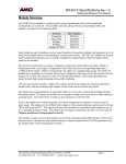
The solution to this problem is to simply provide an additional load resistor, RLoad, in the
form of a 470Ω
Ω οr 560Ω resistor, which will cause the controllers output to very quickly
drop to zero when the output turns off. You can use a 1W resistor if your PTO output is
being powered by a 5V to 12Vdc supply. A 2W resistor will be necessary if your PTO output
is powered by a 24Vdc supply that is normally on.
Stepper Driver
RLim
PTO Output
RLoad
+Step
Controller / Indexer
-Step
COM
+Vdc
Power Supply
COM +Vdc
20 Gear Drive, Plymouth Industrial Park, Terryville, CT 06786
Tel: (860) 585-1254 Fax: (860) 584-1973 Web: www.amci.com
page: 1
Frequently Asked Questions
The value of current limiting resistor RLim shown in the above diagram will vary with the
Power Supply used to power the PTO output. The following table shows the possible values
of this Rlim resistor.
Vdc
5V
12V
15V
24V
RLim
None
2.0kΩ
2.0kΩ
3.9kΩ
It will not be necessary to use resistor RLim if your stepper driver has a
universal input with an operating range of 5 to 24Vdc.
The driver’s user’s manual will indicate if your driver has a 5V only or
universal input.
7. The power supply used to power the PTO output is the second of the two reasons that your
stepper system runs erratically when being controlled by a PTO output. There are two
possible causes.
First, the power supply is not well filtered, which may be the case with some generic low cost
power supplies.
Second, the power supply is also powering inductive loads, such as relays, solenoids, or
contactors.
In both cases, the electrical noise on the power supply is being passed through the PTO
output to the stepper driver input. This noise is interpreted by the driver as steps pulses,
which will cause the motor to run erratically.
If the problem is with a supply that is not well filtered, you can either replace the supply or
add additional filter caps to the system.
If the problem is inductive loads, add surge suppression devices at the input coils of your
inductive loads. A dedicated power supply that is only supplying power to the PTO output
will also solve the problem of inductive loads.
File: FAQ_stepper_erratically.doc
Date: 9/9/09
20 Gear Drive, Plymouth Industrial Park, Terryville, CT 06786
Tel: (860) 585-1254 Fax: (860) 584-1973 Web: www.amci.com
page: 2