1
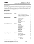
NX2E4X Manual Rev 2.1
Four Channel SSI Network Interface
Overview
The AMCI NX2E4X, where the second “X” indicates the network type, is a stand alone unit that is used
to connect up to four SSI sensors to a network. The available networks, along with the corresponding
AMCI part number are shown in the following table.
Network
DeviceNet
Ethernet
Profibus
Modbus TCP/IP
Part Number
NX2E4D
NX2E4E
NX2E4P
NX2E4T
The NX2E4C ControlNet SSI interface is not covered by this manual. It has its own separate manual that
is available on the following page of our website http://www.amci.com/documents.asp
The NX2E4X uses twenty-eight 16 bit input words and thirty-three 16 bit output words to communicate
with the network.
Sample programs for this and other AMCI products are available from the following page of our website.
http://www.amci.com/sampleprograms.asp
20 Gear Drive, Plymouth Industrial Park, Terryville, CT 06786
Tel: (860) 585-1254 Fax: (860)584-1973 E-mail: [email protected]
page: 1
NX2E4X Manual Rev 2.1
Four Channel SSI Network Interface
Table of Contents
3
General Information
Installation
Chapter 1
Hardware Overview
Specifications
Mounting
Wiring
SSI Protocol
4
4
6
7
10
10
Programmable Parameters
Chapter 2
SSI Clock Frequency
Number of SSI Data Bits
Most Significant Bit
Number of Clock Bits
Data Type (binary or gray code)
Data Logic
Scalar Multiplier and Divisor
Determining Multiplier and Divisor
Preset Value
Apply Preset
Count Direction
Rate Update Time
LED Enable
11
11
11
11
11
11
11
12
12
13
13
14
14
14
Input Registers
Chapter 3
Status Word / Status Bits
15
16
Output Registers
Chapter 4
Control Word
Configuration Word
Programming Sequence
EEPROM Memory
17
18
18
19
19
Network Configurations
Chapter 5
NX2A4D DeviceNet
NX2A4E Ethernet IP
NX2A4P Profibus
NX2A4T Modbus TCP/IP
20
20
22
25
28
Revision History
Chapter 6
32
20 Gear Drive, Plymouth Industrial Park, Terryville, CT 06786
Tel: (860) 585-1254 Fax: (860)584-1973 E-mail: [email protected]
page: 2
NX2E4X Manual Rev 2.1
Four Channel SSI Network Interface
General Information
Important User Information
The products and application data described in this manual are useful in a variety of different
applications. Therefore, the user and others responsible for applying these products described herein are
responsible for determining the acceptability for each application. While efforts have been made to
provide accurate information within this manual, AMCI assumes no responsibility for the application or
the completeness of the information contained herein. Throughout this manual the following two notices
are used to highlight important points.
WARNINGS tell you when people may be hurt or equipment may be damaged if the procedure is not
followed properly.
CAUTIONS tell you when equipment may be damaged if the procedure is not followed properly. No
patent liability is assumed by AMCI, with respect to use of information, circuits, equipment, or software
described in this manual. The information contained within this manual is subject to change without
notice. UNDER NO CIRCUMSTANCES WILL ADVANCED MICRO CONTROLS, INC. BE
RESPONSIBLE OR LIABLE FOR ANY DAMAGES OR LOSSES, INCLUDING INDIRECT OR
CONSEQUENTIAL DAMAGES OR LOSSES, ARISING FROM THE USE OF ANY INFORMATION
CONTAINED WITHIN THIS MANUAL, OR THE USE OF ANY PRODUCTS OR SERVICES
REFERENCED HEREIN.
Standard Warranty
ADVANCED MICRO CONTROLS, INC. warrants that all equipment manufactured by it will be free
from defects, under normal use, in materials and workmanship for a period of [18] months. Within this
warranty period, AMCI shall, at its option, repair or replace, free of charge, any equipment covered by
this warranty which is returned, shipping charges prepaid, within 18 months from date of invoice, and
which upon examination proves to be defective in material or workmanship and not caused by accident,
misuse, neglect, alteration, improper installation or improper testing. The provisions of the “STANDARD
WARRANTY” are the sole obligations of AMCI and excludes all other warranties expressed or implied.
In no event shall AMCI be liable for incidental or consequential damages or for delay in performance of
this warranty.
Returns Policy
All equipment being returned to AMCI for repair or replacement, regardless of warranty status, must have
a Return Merchandise Authorization number issued by AMCI. Call (860) 585-1254 with the model and
serial numbers along with a description of the problem. A “RMA” number will be issued. Equipment
must be shipped to AMCI with transportation charges prepaid. Title and risk of loss or damage remains
with the customer until shipment is received by AMCI.
24 Hour Technical Support Number
Technical Support, in the form of documents, FAQs, and sample programs, is available from our website,
www.amci.com. 24 Hour technical support is also available on this product. For technical support, call
(860) 585-1254. Your call will be answered by the factory during regular business hours, Monday
through Friday, 8AM - 5PM EST. During non-business hours, an automated system will ask you to leave
a detailed message and the telephone number that you can be reached at. The system will page an
engineer on call. Please have your product model number and a description of the problem ready before
you call.
20 Gear Drive, Plymouth Industrial Park, Terryville, CT 06786
Tel: (860) 585-1254 Fax: (860)584-1973 E-mail: [email protected]
page: 3
NX2E4X Manual Rev 2.1
Four Channel SSI Network Interface
Chapter 1: Installation
NX2E4X Hardware Overview
Sensor 1
Sensor 2
Sensor 3
Sensor 4
1234567
1234567
1234567
1234567
Power
Status
LDT Status LEDs
1
2
3
AMCI
4
Power
Connector
123
+ - GND
24 VDC
RS485
Nexus
Digital
Interface
Network Status and Interface
(See the Network installation guides in
chapter 5.)
Status LEDs
Function
LED Enabled
Module Fault
LED Pattern
solid green
solid red
It is possible to enable or disable the LEDs when programming the Nexus module. The default
LED function has only status LED 1 enabled. The NX2E4X status LED’s do not indicate any
problem with the sensor or with the connections to the sensor.
Power Connector
Pin
1
2
3
Function
+24Vdc
DC Common
Shields
The NX2E4X requires 0.5A of current @24Vdc to operate. If the sensor is being powered from
the Nexus unit, add its power requirements to those of the Nexus.
20 Gear Drive, Plymouth Industrial Park, Terryville, CT 06786
Tel: (860) 585-1254 Fax: (860)584-1973 E-mail: [email protected]
page: 4
NX2E4X Manual Rev 2.1
Four Channel SSI Network Interface
Sensor Connectors
The Sensor Input Connectors, labeled “SENSOR
1” through “SENSOR 4” have seven contacts. The
mating connectors are supplied with the
NX2E4X. The AMCI part number for the mating
connector is MS-7P, while the Phoenix Contact
part number is MC1,5/7-ST-3,81, order number
1803620.
The +24Vdc Output pin, (#6), is directly connected to the +24Vdc pin
on the Power connector of the NX2E4X. If your SSI sensor uses
+24Vdc as its power source, then you can use this pin to power the
sensor. DO NOT APPLY +24Vdc TO THIS PIN. Doing so will damage
the NX2E4X and possibly your power supply.
20 Gear Drive, Plymouth Industrial Park, Terryville, CT 06786
Tel: (860) 585-1254 Fax: (860)584-1973 E-mail: [email protected]
page: 5
NX2E4X Manual Rev 2.1
Four Channel SSI Network Interface
Module Specifications
Throughput Time
192µs minimum, 468µs maximum. The rate at which data is updated to the network is also dependent on
how often the sensor updates its data, and the network update time.
Data I/O Words
Requires a maximum of 28 input and 33 output words.
Compatible Transducers
Any transducer that outputs data in single word SSI format. Number of bits transferred is programmable
from 1 to 32. Multi-word transfers are not supported.
Number of Transducer Inputs
Four
Transducer Input Isolation
Optically Isolated (1,500 Vac)
Programmable Parameters
SSI Clock Frequency
MSB Number
Number of SSI Bits
Data Type
Number of Data Bits
Data Logic
Scalar Multiplier
Scalar Divisor
Preset Value
Count Direction
Rate Update Time
LED Disable
Data Value (position) Range
±268,435,455 counts max.
Data Value (position) Preset
Data Value can be preset to any value within the position range.
Rate of Change (velocity) Range
±268,435,455 counts per second max.
Rate of Change (velocity) Resolution
Determined by, and identical to, the Data Value resolution.
Program Memory
EEPROM. Rated for 100,000 write cycles
Data Available to Network
Data Value, Rate of Change, status bits, and Actual SSI data.
NX2E4X Mounting
DIN rail or panel mount. Kit included with unit that allows customer to change mounting styles.
DIN channel, not supplied with the NX2E4X, can be EN 50 002 or EN 50 035.
Environmental Conditions
Operating Temperature: 0 to 60°C
Relative Humidity 5 to 95% (without condensation)
Storage Temperature: -40 to 85°C
NEMA Rating
NEMA 1. Must be mounted in a suitable enclosure to protect it from airborne and liquid contaminates.
20 Gear Drive, Plymouth Industrial Park, Terryville, CT 06786
Tel: (860) 585-1254 Fax: (860)584-1973 E-mail: [email protected]
page: 6
NX2E4X Manual Rev 2.1
Four Channel SSI Network Interface
Mounting the NX2E4X
The next two pages show the NX2E4X in its DIN rail and panel mount configurations. The mounting kit,
included with the unit, contains two DIN brackets, two panel brackets, and four #8 screws needed to
attach your choice of brackets to the NX2E4X. Note that the unit is not sealed and the NX2E4X must be
installed in an adequate enclosure to protect it from environmental contaminates.
DIN Rail Mounting
As shown in the following figure, the unit can be DIN rail mounted in two ways. The brackets accept EN
50 002 or EN 50 035 channel. Note that DIN channel is not included with the NX2E4X.
20 Gear Drive, Plymouth Industrial Park, Terryville, CT 06786
Tel: (860) 585-1254 Fax: (860)584-1973 E-mail: [email protected]
page: 7
NX2E4X Manual Rev 2.1
Four Channel SSI Network Interface
Panel Mounting
As shown in the figure below, the NX2E4X can be panel mounted in two ways. The mounting kit,
included with the unit, contains the two panel brackets and four #8 screws needed to attach the brackets.
The slots in the brackets for mounting the unit to the panel are made to accept #8 screws or bolts. The
lengths of these screws or bolts depends on your application, and are not included with the unit.
Panel Mounting Brackets, Rear Mount Position.
Panel Mounting Brackets, Foot Mount Position.
20 Gear Drive, Plymouth Industrial Park, Terryville, CT 06786
Tel: (860) 585-1254 Fax: (860)584-1973 E-mail: [email protected]
page: 8
NX2E4X Manual Rev 2.1
Four Channel SSI Network Interface
Attaching the DIN Brackets
The following figure shows how to install the DIN brackets so that the NX2E4X can be mounted on EN
50 022 or EN 50 035 rail. Note that the bottom view of the unit is shown. The rear view is similar and the
brackets are installed in the same fashion.
Attaching the Panel Brackets
The following figure shows how to install the panel brackets so that the NX2E4X can be securely
mounted to an enclosure. Note that the bottom view of the unit is shown. The rear view is similar and the
brackets are installed in the same fashion.
Transducer Mounting
Follow the mounting instruction you received with your SSI transducer.
20 Gear Drive, Plymouth Industrial Park, Terryville, CT 06786
Tel: (860) 585-1254 Fax: (860)584-1973 E-mail: [email protected]
page: 9
NX2E4X Manual Rev 2.1
Four Channel SSI Network Interface
Transducer Cable Installation
Follow the transducer manufacturers suggestions when specifying the transducer cable. Pre-assembled
and tested cables are usually offered by the manufacturer. When installing the transducer cable, follow
these general guidelines.
SSI signals are low voltage, low power signals. SSI cables must use shielded cable and can be
installed in conduit along with other low power cabling such as communication cables and low power
ac/dc I/O lines. They cannot be installed in conduit with ac power lines or high power ac/dc I/O lines.
Most factory automation manufacturers offer excellent written guidelines for cabling installation that
you can refer to for additional information..
The shields of the transducer cable must be grounded at one point only! When installing the cable,
treat the shield as a signal carrying conductor and do not connect the shield to ground at any junction
box.
1) If you are making your own transducer cable, ground the shields at the NX2E4X by connecting
them to the Shields pin (#7) of the Sensor Input Connector. Do not connect the shields to the
body of the transducer.
2) If you are using a pre-made cable, or the SSI transducer has an integral cable, verify that the
shields are electrically isolated from the body of the transducer. If they are connected, then
properly ground the body of the transducer and DO NOT connect the shields to Shields pin (#7)
of the Sensor Input Connector. The preferred grounding connection for the transducers’ shields
is at the NX2E4X. Use this point unless the shields are connected to the body of the transducer
through a pre-made or integral cable. Following this practice will eliminate ground loops that
could damage the transducer or NX2E4X.
SSI Protocol
The following figure shows how a NX2E4X reads data from a SSI transducer. Note that the formal SSI
definition allows for twenty-four bits of data and a twenty-fifth stop bit. However, AMCI is aware of
some transducers that transmit more or less than twenty-five bits. To accommodate these transducers, the
NX2E4X can be programmed to accept up to thirty-two bits in the SSI bit stream.
“n” = Number of bits in the SSI data. Range of 1 to 32. Default of 24.
1. The first falling edge of the clock signal latches the SSI data. Note: Some transducers latch the
data at the end of the previous interrogation.
2. The next “n” rising edges of the clock shift out the “n” data bits.
3. TINT is the time between interrogations and is equal to 500µS for the NX2E4X. TM is the time
that the Stop bit is valid, which is typically 12 to 20 µS. TIDL is the time between the end of the
last interrogation and the start of the next and is fixed at 120µS. The transducer must have new
data available within the TIDL Time period if the system is to work properly.
20 Gear Drive, Plymouth Industrial Park, Terryville, CT 06786
Tel: (860) 585-1254 Fax: (860)584-1973 E-mail: [email protected]
page: 10
NX2E4X Manual Rev 2.1
Four Channel SSI Network Interface
Chapter 2: Programmable Parameters
The NX2E4X is configured by programming its Programmable Parameters. These parameters are broken
down into two groups, SSI Setup parameters and Data Setup parameters.
SSI Setup Parameters:
These parameters are used to extract the SSI Data Value from the bit stream. These parameters
define the clock speed of the data transfer, the number of clock bits, the position and length of the
SSI data within the bit stream, and the format of the data.
SSI Clock Frequency: This parameter allows you to set the SSI clock frequency to one of four
values; 125kHz, 250kHz, 500kHz, or 1.0MHz. The default value of 125kHz value will work in all
applications. Your sensor’s user manual should contain information on what SSI Clock Frequency
is appropriate for both the sensor and the type and length of cable used.
Number of SSI Data Bits: This parameter defines how many bits of the data stream make up the
Data Value. This parameter has a range of 1 to 28 and a default of value of 24.
Most Significant Bit (MSB) Number: This parameter defines the bit location of the first bit of the
Data Value in the data bit stream. This parameter has a range of 1 to 32 and a default value of 1.
Number of SSI Clock Bits: This value sets the number of bits that the NX2E4X will read from the
SSI transducer per interrogation. This parameter has a range of 1 to 32 and must be greater than or
equal to (Most Significant Bit Number + (Number of SSI Data Bits – 1)). The default value of 24
bits will work in most applications.
Example: You have a 12 bit single turn SSI encoder that outputs 25 SSI Clock bits. The single turn
value is located in the least significant bits of the SSI data.
1
0
2
0
3
0
4
0
5
0
6
0
7
0
8
0
9
0
10
0
11
0
MSB of SSI Clock Bits
12
0
13
0
14
X
15
X
16
X
17
X
18
X
19
X
20
X
MSB of Data Value
21
X
22
X
23
X
24
X
25
X
LSB of Data Value
and Clock bits
In this example, the NX2E4X module would be setup using the following data.
Number of SSI Clock Bits = 25
Most Significant Bit number = 14
Number of SSI Data Bits = 12
Data Type: This parameter tells the NX2E4X module to interpret the SSI data either as a binary
number or as a gray code number. The default value is binary.
You must read all of the data bits from a Gray Code sensor. The data
value will appear to count up and down if you use the MSB Number and
Number of Data Bit parameters to read only some of the data bits.
Data Logic: This parameter is included to handle situations where the SSI data is reported with
negative logic. If this parameter is set, the NX2E4X will invert the data bits before performing any
scaling and decoding operations. When left in its default value of positive, the NX2E4X module
will use the SSI data as it is from the sensor.
20 Gear Drive, Plymouth Industrial Park, Terryville, CT 06786
Tel: (860) 585-1254 Fax: (860)584-1973 E-mail: [email protected]
page: 11
NX2E4X Manual Rev 2.1
Four Channel SSI Network Interface
Data Setup Parameters:
Once the NX2E4X module has extracted the SSI data from the data stream, it uses the Data Setup
Parameters to convert the raw SSI data into the Data Value it reports to the PLC.
Scalar Multiplier & Divisor: These two parameters are used to scale the SSI data. Both
parameters have a default value of one and can range in value from 1 to 32,767. The Scalar
Multiplier must be less than or equal to the Scalar Divisor. In other words, the ratio of Multiplier to
Divisor CANNOT be greater than one.
Linear displacement transducers from Balluff and MTS have resolutions measured in µm/count.
The NX2E4X module can easily convert this data into the more familiar US Customary system of
inches. The table below shows the Multiplier and Divisor values needed to convert from various
metric resolutions to US Customary resolutions. For example, to convert data from a LDT sensor
with 5µm/count resolution to 0.0005 inch/count resolution, use a Multiplier of 50 and a Divisor of
127.
LDT
Resolution
1µ
µm
2µ
µm
5µ
µm
10µ
µm
20µ
µm
Desired Resolution
0.00005” 0.0001” 0.0002” 0.0005” 0.001”
100
50
25
10
5
127
127
127
127
127
100
50
20
10
127
127
127
127
125
50
25
127
127
127
100
50
127
127
100
127
40µ
µm
0.002”
5
254
5
127
25
254
25
127
50
127
100
127
0.005”
1
127
2
127
5
127
10
127
20
127
40
127
Use the following procedure to calculate your Scalar Multiplier and Divisor values if either your
LDT Resolution or Desired Resolution does not appear in the above table.
Conversion Factor:
Desired Resolution (counts/inch)
LDT Resolution (counts/inch)
Step 1: Convert your LDT resolution from µm to inches. For example, you are using a sensor with
1 µm resolution.
1 µm * 1mm * 1 inch
=
1000 µm 25.4 mm
0.00003937 inches/count = 25400 counts/inch
Step 2: Determine the number of counts per inch for the desired resolution. For example, if you
want to measure with 0.0001 inch resolution,
0.0001 inch/count = 10000 counts/inch
20 Gear Drive, Plymouth Industrial Park, Terryville, CT 06786
Tel: (860) 585-1254 Fax: (860)584-1973 E-mail: [email protected]
page: 12
NX2E4X Manual Rev 2.1
Four Channel SSI Network Interface
Step 3: Determine the Scalar Multiplier and Divisor values.
Desired Resolution (counts/inch) = 10000 counts/inch = 100 = 50
LDT Resolution (counts/inch)
25400 counts/inch 254 127
Therefore, to use a sensor with 1mm resolution and get 0.0001 inches per count resolution, use a
Scalar Multiplier of 50 and a Scalar Divisor of 127.
Preset Value: The zero position of the SSI encoder’s Data Value may not match the zero position
of your machine. The Preset Value parameter gives you the ability to offset the Data Value from
the actual SSI data to a value that will be more useful for your application.
Programming the Preset Value parameter does not change the Data Value. The Preset Value is
stored in the NX2E4X module’s memory until the module sees the Apply Preset bit during a
programming cycle.
Apply Preset: Offsetting the Data Value to the Preset Value is a two step operation. First, the
Preset Value, which is part of channel’s setup data, must be saved in the module’s memory.
Second, setting the Apply Preset bit will change the Data Value to the Preset Value. These two
operations MUST be performed separately. It is NOT possible to both program the Preset Value
and Apply the Preset in one programming cycle.
Setting the Apply Preset bit causes the module to generate an internal offset value that is applied to
the Data Value before it is reported to the PLC. This internal offset is saved in the NX2E4X
module’s memory, so it is not necessary to home the module at every power up.
The NX2E4X EEPROM memory is guaranteed for 100,000 write
cycles before writing to it will cause it to fault. Therefore continuously
Applying the Preset should be avoided. If your application requires you
to continuously Apply the Preset, consider calculating and Applying the
Preset in your PLC program
Programming the NX2E4X’s setup parameters will reset the internal
offset generated by an Apply Preset operation. If you are
programming the unit’s setup parameter at every power up, this may
cause your data value to not be absolute through power down.
20 Gear Drive, Plymouth Industrial Park, Terryville, CT 06786
Tel: (860) 585-1254 Fax: (860)584-1973 E-mail: [email protected]
page: 13
NX2E4X Manual Rev 2.1
Four Channel SSI Network Interface
Count Direction: This parameter is useful if your Data Value represents a linear position. It gives
you the ability to reverse the direction of motion needed to increase the position count. For
simplicity’s sake, the two values for this parameter are called Positive Direction and Negative
Direction. When this parameter is set to its default of Positive, the Data Value is not changed.
When this parameter is set to Negative, the Data Value is multiplied by -1 before it is reported. For
linear transducers, this has the effect of reversing the direction of motion needed to increase the
count. When using LDT’s and the Count Direction is set to Positive, the Data Value usually
increases as the magnet moves away from the head of the LDT. When the Count Direction is set to
Negative, the Data Value increases as the magnet moves towards the head of the LDT.
You will need to Apply the Preset the Data Value after you program the Count Direction parameter.
If your Data Value represents a rotary position, you cannot change the count direction with this
parameter. However, you can easily reverse the count direction with ladder logic. This can easily
be accomplished with two rungs of logic.
Rung 1: If the data value is equal to zero, simply copy the current data value into your reversed
count direction register. The zero point is the same for both directions of rotation.
Rung 2: If the data value is not equal to zero, subtract the current data value from the maximum
value that your rotary encoder will output.
Rate Update Time: The Velocity Update Time parameter sets the amount of time between Rate of
Change information updates to the PLC. Its can be set to either 24 milliseconds or 160
milliseconds, with 160 milliseconds being the default. Decrease the time between updates for faster
response to changes in this value. Increase the time between updates for better averaging of this
value.
The Velocity data is measured in Counts/Second.
LED Enable: This parameter gives you the ability to enable or disable the Unit Status LED of the
corresponding Sensor Input Channel. When disabled, the LED is always off and does not show the
status of the NX2E4E. The channel will continue to function, regardless of the state of the LED.
20 Gear Drive, Plymouth Industrial Park, Terryville, CT 06786
Tel: (860) 585-1254 Fax: (860)584-1973 E-mail: [email protected]
page: 14
NX2E4X Manual Rev 2.1
Four Channel SSI Network Interface
Chapter 3: Input Data
(Data sent from the NX2E4X to the network)
The NX2E4X reports Status information, Data Values, Velocity Values, and Actual SSI Data to the
network using twenty-eight 16 bit words. The following table shows the layout of these words.
Channel
1
2
3
4
Word
0
1
2
3
4
5
6
7
8
9
10
11
12
13
14
15
16
17
18
19
20
21
22
23
24
25
26
27
Function
Channel 1 Status
Upper 4 digits Channel 1 data value
Lower 4 digits Channel 1 data value
Upper 4 digits Channel 1 velocity
Lower 4 digits Channel 1 velocity
Upper 16 bits Channel 1 Actual SSI Data
Lower 16 bits Channel 1 Actual SSI Data
Channel 2 Status
Upper 4 digits Channel 2 data value
Lower 4 digits Channel 2 data value
Upper 4 digits Channel 2 velocity
Lower 4 digits Channel 2 velocity
Upper 16 bits Channel 2 Actual SSI Data
Lower 16 bits Channel 2 Actual SSI Data
Channel 3 Status
Upper 4 digits Channel 3 data value
Lower 4 digits Channel 3 data value
Upper 4 digits Channel 3 velocity
Lower 4 digits Channel 3 velocity
Upper 16 bits Channel 3 Actual SSI Data
Lower 16 bits Channel 3 Actual SSI Data
Channel 4 Status
Upper 4 digits Channel 4 data value
Lower 4 digits Channel 4 data value
Upper 4 digits Channel 4 velocity
Lower 4 digits Channel 4 velocity
Upper 16 bits Channel 4 Actual SSI Data
Lower 16 bits Channel 4 Actual SSI Data
Units
Scaled
Counts
Counts /
Second
Scaled
Counts
Counts /
Second
Scaled
Counts
Counts /
Second
Scaled
Counts
Counts /
Second
Note 1: The data and the velocity values are divided into two words. The upper word contains the
10,000s places while the lower word contains the 1000s, 100s, 10s, and 1s places. For example,
a value of 123,456 would have 12 in the upper word and 3456 in the lower word. To combine
the two values into one register, multiply the upper word by 10,000 and add the lower word to it.
There is also a Data Value Sign bit in the Channel Status words. When this bit is set, the data
value is negative. You can take the state of this bit into account by multiplying your combined
data value by –1 whenever this bit is set
Note 2: The Actual SSI Data is the unmodified data as it is received directly from the sensor. That is,
before any offset, scalars, or data conversion operations are performed. This data is reported to
allow you to detect any error or status bits that your sensor may place in the data stream.
Note 3: All of the SSI bits will be reset to zero if there is no working SSI sensor attached to the channel.
20 Gear Drive, Plymouth Industrial Park, Terryville, CT 06786
Tel: (860) 585-1254 Fax: (860)584-1973 E-mail: [email protected]
page: 15
NX2E4X Manual Rev 2.1
Four Channel SSI Network Interface
Status Word Layout
Velocity Overflow:
Module Fault:
Acknowledge Bit:
0
Bit
04
Bit
03
Bit
02
Bit
01
Bit
00
Configuration Error
Velocity at Zero:
Bit
05
Constant Error
Data Value Sign:
Bit
06
Scalar Divisor Error
Motion Direction:
Bit
07
Scalar Multiplier Error
Message Ignored:
Bit
08
Preset Value Error
Preset Value Error:
Command Error:
Bit
09
Command Error
Divisor Error:
Multiplier Error:
0
Bit
10
Message Ignored
Configuration Error:
Constant Error:
Bit
11
Velocity at zero
Module Error
0
Bit
12
Motion Direction
(0=increasing, 1=decreasing)
Acknowledge bit (ch 1 only)
Bit
13
Data Value Sign
0 = positive 1 = negative
Bit
14
Velocity Overflow
Bit
15
Set if any of the unused bits in the configuration word are set
This bit is set if the number of the SSI bits, the number of data bits, or the MSB
number is outside the limits (1…32). This is also true if the (Number of Data
bits + (MSB Number-1)) > the Number of the SSI Clock bits.
The Scalar Divisor is outside the expected range (1 to 32767)
Set if the Scalar Multiplier is outside the range of (1 to 32767), or if the
multiplier parameter is greater than the divisor parameter.
Set if the preset value is outside of the range of +268,435,455.
Set if any of unused bits in the command word are set, or if you try to both
program the Setup Data and Apply the Preset value to a channel in one
programming sequence.
Set if an attempt is made to program a channel if an error already exits on a
different channel. This bit will not be set if the same channel is programmed a
second time with incorrect data.
This bit will be “0” if the data value is increasing, or “1” if the data value is
decreasing. The bit will remain in its last state when there is no motion.
This bit will be “0” if the data value is positive, or “1” if the data value is
negative. To use, multiply the combined data value by –1 whenever this bit is
set.
This bit will be set if there has been no motion for the last portion of the Velocity
Update Time.
This bit will be set if the rate of change value exceeds 2^32 counts per second.
When this occurs, the last valid value is sent to the processor.
Set on EEPROM or PLD fault.
Set when the NX2E4X detects that Transmit bit is set in the output registers.
This bit is present only in the channel 1 status word.
20 Gear Drive, Plymouth Industrial Park, Terryville, CT 06786
Tel: (860) 585-1254 Fax: (860)584-1973 E-mail: [email protected]
page: 16
NX2E4X Manual Rev 2.1
Four Channel SSI Network Interface
Chapter 4: Output Data
Channel
All
1
2
3
4
Word
0
1
2
3
4
5
6
7
8
9
10
11
12
13
14
15
16
17
18
19
20
21
22
23
24
25
26
27
28
29
30
31
32
(Data sent from the network to the NX2E4X)
Function
Control
Configuration
Number of SSI Clock Bits
MSB Number
Number of Data Bits
Scalar Multiplier
Scalar Divisor
Upper 4 Digits Preset Value +sign
Lower 4 Digits Preset Value
Configuration
Number of SSI Clock Bits
MSB Number
Number of Data Bits
Scalar Multiplier
Scalar Divisor
Upper 4 Digits Preset Value +sign
Lower 4 Digits Preset Value
Configuration
Number of SSI Clock Bits
MSB Number
Number of Data Bits
Scalar Multiplier
Scalar Divisor
Upper 4 Digits Preset Value +sign
Lower 4 Digits Preset Value
Configuration
Number of SSI Clock Bits
MSB Number
Number of Data Bits
Scalar Multiplier
Scalar Divisor
Upper 4 Digits Preset Value +sign
Lower 4 Digits Preset Value
Range
See Description Below
See Description Below
1 to 32
1 to 32
1 to 28
1 to Divisor
1 to 32767
Default
± 268,435,455
0
See Description Below
1 to 32
1 to 32
1 to 28
1 to Divisor
1 to 32767
24
1
24
1
1
± 268,435,455
0
See Description Below
1 to 32
1 to 32
1 to 28
1 to Divisor
1 to 32767
24
1
24
1
1
± 268,435,455
0
See Description Below
1 to 32
1 to 32
1 to 28
1 to Divisor
1 to 32767
24
1
24
1
1
± 268,435,455
0
24
1
24
1
1
Note 1: The Number of SSI Clock Bits must be greater than or equal to the sum of the (MSB Number +
(Number of Data Bits – 1)).
Note 2: The Preset Value is divided into two words. The upper word contains the 10,000s places while
the lower word contains the 1000s, 100s, 10s, and 1s places. For example, a value of 123,456
would have 12 in the upper word and 3456 in the lower word.
Note 3: Negative Preset Values are transmitted with bit 15, the Most Significant Bit, set in the Preset
Value’s upper word.
20 Gear Drive, Plymouth Industrial Park, Terryville, CT 06786
Tel: (860) 585-1254 Fax: (860)584-1973 E-mail: [email protected]
page: 17
NX2E4X Manual Rev 2.1
Four Channel SSI Network Interface
Control Word
0
0
0
0
0
0
Bit
07
Bit
06
Bit
05
Bit
04
Bit
03
Bit
02
Bit
01
Bit
00
Apply Preset Channel 1
Bit
08
Apply Preset Channel 2
Bit
09
Apply Preset Channel 3
Bit
10
Apply Preset Channel 4
Bit
11
Program Channel 1 Setup
Clear Error
Bit
12
Program Channel 2 Setup
Transmit Bit (ch 1 only)
Bit
13
Program Channel 3 Setup
Bit
14
Program Channel 4 Setup
Bit
15
Bit
05
Bit
04
Bit
03
Bit
02
Bit
01
Bit
00
0
0
0
Configuration Word
Bit
10
0
0
0
Bit
09
Bit
08
Clock
Frequency
00=1MHz
01=500kHz
10=250kHz
11=125kHz
Bit
07
Bit
06
0
Direction of Increasing Counts
0 = Positive, 1 = Negative
Bit
11
Rate Update Time
0 = 160ms, 1 =24ms
0
Bit
12
SSI Data Logic
0 = positive 1 =negative
0
Bit
13
SSI Data Type
0 = binary 1 = Gray Code
Bit
14
Enable Channel LED
0 = disabled, 1 = enabled
Bit
15
Notes
1. The Configuration Word has a default value of 0.
A Configuration Error will be generated if any of the Configuration Word’s unused bits (1, 3, 4,
5, 10, 11, 12, 14, and 15) are set.
3. The Count Direction parameter is useful if the Data Value represents a linear position. It gives
you the ability to reverse the direction of motion needed to increase the position count. Changing
the direction of increasing counts changes the data value sign bit in the input register’s status
data. The absolute value of the data value is not affected.
2.
This parameter will not reverse the direction of increasing counts of a rotary encoder.
The default clock frequency is 1MHz.
5. A Command Error will be generated if you try to both Apply the Preset and Program a channel in
a single programming sequence. However, it is possible to program a channel while Applying
the preset of a different channel.
6. All of the channel’s setup data must be present and valid before it will be accepted during a
programming cycle.
7. If a programming error exists on any of the channels, the error must be cleared before a different
channel can be programmed.
8. It is possible to enable or disable the four status LEDs. The channels are always are enabled, and
will function normally, even if the LED is disabled. By default, only the channel 1 LED is
enabled.
4.
20 Gear Drive, Plymouth Industrial Park, Terryville, CT 06786
Tel: (860) 585-1254 Fax: (860)584-1973 E-mail: [email protected]
page: 18
NX2E4X Manual Rev 2.1
Four Channel SSI Network Interface
Programming Sequence
1. The controller’s program writes the data into the output registers.
2. The controller’s program then sets the Transmit Bit.
3. When the module detects the 0 to 1 transition of the transmit bit, it will respond by setting any error
bits in the channel status words, and the Acknowledge bit, which is bit 15 in the channel 1 status
word.
4. When the controller’s program sees that the Acknowledge bit is set, it will examine any error bits, and
then reset the Transmit Bit.
5. The module will reset the Acknowledge bit.
6. The programming sequence is now complete.
EEPROM Parameter Memory
Parameter values are stored in a non-volatile EEPROM memory. This memory type can store
parameter values in the absence of power for over twenty years, but you can only write to it a
limited number of times before it will be damaged. The EEPROM that AMCI uses is guaranteed
for a minimum of 100,000 write cycles.
Every time the Apply Preset command is issued, the NX2E4X calculates
and stores an offset value in its EEPROM memory. If your application
requires you to continuously Apply the Preset Value, consider performing
the preset operation in your ladder logic program.
20 Gear Drive, Plymouth Industrial Park, Terryville, CT 06786
Tel: (860) 585-1254 Fax: (860)584-1973 E-mail: [email protected]
page: 19
NX2E4X Manual Rev 2.1
Four Channel SSI Network Interface
Chapter 5: Network Connections
NX2E4D Hardware Overview
Sensor 1
Sensor 2
Sensor 3
Sensor 4
1234567
1234567
1234567
1234567
Power
Status
LDT Status LEDs
1
2
3
AMCI
4
123
+ - GND
24 VDC
RS485
1
2
DeviceNet
Status LEDs
DeviceNet Connector
Pin Number
1
2
3
4
5
Function
+24Vdc
Can High
Shields
Can Low
Common
Nexus
3
4
Switches for Node
Address and Baud
Rate
Power
Connector
12345
Switch 1
Digital
Interface
DeviceNet
Connector
Standard Wire Color
Red
White
Bare
Blue
Black
Note: The NX2E4D will
draw 16mA @ 24Vdc of
current from the DeviceNet
Network.
Node Address and Baud Rate Selection
The NX2E4D uses eight DIP switches to select the Node Address and the Baud Rate. Switches 1
and 2 set the Baud rate and switches 3 to 8 set the node, with switch 8 being the least significant bit.
The following table shows the possible switch setting combinations.
The DIP switch package is mounted so that the numbers are upside down. However, “1” or “ON” is
still in the up position and “0” or “OFF” is in the down position.
The state of the switch settings is only taken into account at power up
Baud Rate
125k
250k
500k
Reserved
Switches 1 & 2
12
00
01
10
11
Node Address
0
1
2
61
62
63
Switches 3 to 8
345678
000000
000001
000010
111101
111110
111111
Example: For a Baud Rate = 250K and the Node Address = 5, switches 2, 6, and 8 would be ON, up
towards the top of the module and switches 1, 3, 4, 5, and 7 would be OFF, down towards
the bottom of the module.
20 Gear Drive, Plymouth Industrial Park, Terryville, CT 06786
Tel: (860) 585-1254 Fax: (860)584-1973 E-mail: [email protected]
page: 20
NX2E4X Manual Rev 2.1
Four Channel SSI Network Interface
DeviceNet Status LEDs
The following table describes the function of the four network status LEDs.
LED
Number
Name
1
Module
Network
Status
2
Network
Status
3
4
Reserved
Reserved
LED Pattern
Steady Off
Steady Red
Steady Green
Flashing Red
Steady Off
Steady Red
Steady Green
Flashing Red
Flashing Green
Description
No Power
Unrecoverable Fault
Device Operational
Minor Fault
Not Powered / Not On Line
Critical link failure
Link OK, On Line, Connected
Connection Time Out
On Line not connected
Network Update Time
The NX2E4D has a minimum network update time of 5ms.
Adding the NX2E4D to your network
Before the NX2E4D can be attached to a network, it must be added to the RSNetWorx for DeviceNet
software. The EDS and icon files are available in the Tech Library >> Driver Files section of our
website, www.amci.com. The following procedure to add the EDS file to RSNetWorx assumes that you
have already downloaded these files and un-zipped them.
1.
2.
3.
4.
5.
6.
7.
8.
9.
10.
11.
12.
13.
14.
With the power off, use the dip switches on the front of the NX2E4D to set the node address and the
baud rate.
Start RSNetWorx for DeviceNet.
In the RSNetWorx program, click on Tools in the menu bar.
Click on EDS Wizard… from the pull down menu that appears.
Click on Next> in the window that appears.
Select Register an EDS file(s) and click on Next>.
Select Register and EDS file.
Click on Choose File… and navigate to the folder where you placed the un-zipped EDS and icon
files.
Double click on NX2E4D_r02.eds file.
Click on Next>.
Click on NX2E4D_r02.eds file so that it is highlighted.
Click on Next> to assign an icon to the device.
Click on the NX2E4D and then click on Change icon… to select the icon for the Nexus unit. You
can choose one of the built in icons from Rockwell Automation or click on the Browse… button and
select the NX2E4D.ico icon file.
Click on Next> and then click on Finish to complete the installation of the AMCI NX2E4D EDS file
to the RSNetWorx system.
Once the EDS file is added to your system, add the NX2E4D to your network as you would any other
device, including adding it to the scanlist configuration of the scanner module.
20 Gear Drive, Plymouth Industrial Park, Terryville, CT 06786
Tel: (860) 585-1254 Fax: (860)584-1973 E-mail: [email protected]
page: 21
NX2E4X Manual Rev 2.1
Four Channel SSI Network Interface
NX2E4E Hardware Information
Sensor 1
Sensor 2
Sensor 3
Sensor 4
1234567
1234567
1234567
1234567
Power
Status
LDT Status LEDs
1
2
3
AMCI
4
+ - GND
24 VDC
RS485
1
2
Ethernet
Status LEDs
Nexus
3
4
Address DIP
switches
123
Power
Connector
Digital
Interface
Switch 1
RJ45 Ethernet
Connector
Power Up Delay
There is an eight second delay between power up and when the NX2E4X begins to communicate with the
network.
Changing the Ethernet IP Address
The NX2E4E has a default IP address of 192.168.000.XXX where “XXX” can be any number between 1
and 254 and is set by the dip switches located on the front of the module.
Use the following procedure if you want your IP address to be something other than 192.168.000.XXX.
1. Remove power from the Nexus Unit.
2. Set all of the unit’s dip switches to the OFF (Down) position. This will set the unit’s address to
0000 0000.
3. Start and configure your BootP server. Any DHCP/BootP server running on a computer, which is
connected to the same network, may be used for this purpose. Please note that the Nexus Unit’s
MAC ID address is located on a label on the module’s cover.
4. Apply power to the Nexus Unit.
5. At power-up the module will attempt to get an IP address by sending several BootP requests.
This operation will require approximately 30 seconds. At this point LED2 will be flashing green.
If retrieved, the IP configuration will be used and stored in the Nexus Unit’s Flash Memory,
overwriting older IP settings.
6. The Nexus Unit will now join the network with the newly set IP configuration.
7. If a BootP server is not found, the Nexus Unit will use the IP configuration that had been
previously stored in its flash memory.
8. Cycle power to the NX2E4E. The changes to the IP address will not be permanent until power
has been cycle.
20 Gear Drive, Plymouth Industrial Park, Terryville, CT 06786
Tel: (860) 585-1254 Fax: (860)584-1973 E-mail: [email protected]
page: 22
NX2E4X Manual Rev 2.1
Four Channel SSI Network Interface
Ethernet Address Selection using the DIP switches
The NX2E4E uses an IP address of 192.168.000.XXX where “XXX” can be any number between 1 and
254. Eight dip switches on the NX2E4E are used to set the “XXX” portion of the address. Switch 8, the
left most switch, is the least significant bit and switch 1, the right most switch, is the most significant bit.
The address is programmed using the following procedure.
1. Determine the address of the NX2E4E. It can be any unused address between 1 and 254.
2. Convert the address to a binary number. A value of 50 will be 0011 0010.
3. Enter the address on the dip switches. Continuing the above example, switches 8, 6, 5, 2 and 1
will be off (down) and switches 7, 4, and 3 will be on (up).
Ethernet Status LEDs
The following table describes the function of the four network status LEDs.
LED
Number
Name
1
Network
Status
2
Module
Status
3
Activity
LED
4
Link
LED Pattern
Steady Off
Steady Green
Flashing Green
Flashing Red
Steady Red
Flashing Green/Red
Steady Off
Steady Green
Flashing Green
Flashing Red
Steady Red
Flashing Green/Red
Function
The module has no power or on IP address has been assigned.
The module has at least one established Ethernet/IP connection.
There are no Ethernet/IP connections established to the module
One or more of the connections in which this module is the
target has timed out
The module has detected that its IP address is already in use
The module is performing a power on self test
No Power.
The module is operating correctly.
The module has not been initialized.
A minor recoverable fault has been detected.
A major internal error has been detected.
The module is performing a power on self test.
This LED flashes green each time a packet is received or
transmitted
This LED indicates that the module is connected to an Ethernet
network
20 Gear Drive, Plymouth Industrial Park, Terryville, CT 06786
Tel: (860) 585-1254 Fax: (860)584-1973 E-mail: [email protected]
page: 23
NX2E4X Manual Rev 2.1
Four Channel SSI Network Interface
Setup Example
AMCI NX2E4X to Rockwell Automation 1756-ENET/B module
1.
2.
3.
4.
5.
6.
7.
8.
9.
10.
11.
With power removed, use the dip switches to set the address of the NX2E4X.
Open an existing or create a new ControlLogix program.
From the project tree, right click on I/O configuration and select New Module.
From the Module Type list that appears, select 1756-ENET/B, the 1756 Ethernet Bridge module.
Type a name for the Bridge module, which must begin with a letter, in the Name field.
Enter the slot number where the 1756-ENET/B module is located in the ControlLogix rack.
In the Address/Host Name field, select the IP Address and enter the address 192.168.000.XXX
where XXX can be a unique number between 1 and 254.
Click the Finish button.
From the project tree, right click on the 1756-ENET/B module and select New Module.
Select ETHERNET-MODULE Generic Ethernet Module from the list that appears and click on
OK.
In the module properties that appear, enter the following parameters.
Name: Your Choice (must begin with a letter)
Comm Format: Data-INT (must be Data-INT)
IP Address: 192.168.000.XXX where XXX is the number entered on the DIP switches
Input
Output
Configuration
12.
13.
14.
15.
16.
Assembly Instance
100
150
110
Size
28
33
0
Click on Next.
Select the RPI time, minimum = 3ms.
Click on Finish.
Save and download the program to the ControlLogix rack.
While online with the PLC, right click on the Ethernet Bridge module and select Properties.
Click on the Port Configuration tab and modify the following fields.
Enable Bootp: Unselected (This will allow the data to be manually entered in the IP
address and Domain Name fields.)
IP Address: 192.168.000.XXX (must be the same as step 7 above)
Subnet Mask: 255.255.255.0
The Gateway Address, Domain Name, Primary DNS Server Address, and Secondary DNS Server
Addresses all remain unchanged.
20 Gear Drive, Plymouth Industrial Park, Terryville, CT 06786
Tel: (860) 585-1254 Fax: (860)584-1973 E-mail: [email protected]
page: 24
NX2E4X Manual Rev 2.1
Four Channel SSI Network Interface
NX2E4P Hardware Overview
Sensor 1
Sensor 2
Sensor 3
Sensor 4
1234567
1234567
1234567
1234567
Power
Status
LDT Status LEDs
1
2
3
AMCI
4
Profibus
Status LEDs
3
4
123
+ - GND
24 VDC
RS485
1
2
Power
Connector
Nexus
1
Digital
Interface
2
Profibus
Female
Connector
Selects Station
Address
Profibus Status LEDs
LED
Number
1
2
3
4
LED Pattern
Function
Red
Off
Green
Off
Flashing Red 1Hz
Module is Offline and no data exchange is possible
The module is Online
Module is Online and data exchange is possible
The module is Off line
Error in configuration: IN and/or OUT length set during
initialization of the module is not equal to the length set
during the configuration of the network
Error in User Parameter data: The length/contents of the
user parameter data set during initialization of the module is
not equal to the length/contents set during configuration of
the network.
Error in initialization of the Profibus communication ASIC.
No diagnostic present
Not Used
Flashing Red 2Hz
Flashing Red 4Hz
Off
Off
Profibus Connector
The Nexus module uses a 9 pin female D-sub connector to communicate with the Profibus network.
20 Gear Drive, Plymouth Industrial Park, Terryville, CT 06786
Tel: (860) 585-1254 Fax: (860)584-1973 E-mail: [email protected]
page: 25
NX2E4X Manual Rev 2.1
Four Channel SSI Network Interface
Station Address Selection
The Nexus module has two rotary switches used to set the module’s address on the network. Any
station from 0 to 99 can be selected. Switch 1 sets the one digit and switch 2 sets the 10s digit of the
address. For example, if the Nexus is to be installed at station 46, switch 1 would be set to 6, and
switch 2 would be set to 4. Note, changing the station address only takes affect at power up.
Changing the address while power is applied to the Nexus module will generate a minor fault.
Network Baud Rate
The NX2E4P supports the following network baud rates
9.6 kbits/sec, 19.2 kbits/sec, 93.75 kbits/sec, 187.5 kbits/sec, 500 kbits/sec, 1.5 Mbits/sec, 3
Mbits/sec, 6 Mbits/sec, and 12 Mbits/sec
Quick Start Guide
AMCI Nexus to SST-PFB-SLC Profibus interface module
1. If it is not already present, install the SST-PFB-SLC module in the SLC rack and configure the
rack (the ID code is 13635) for the module.
2. Place the PLC in program mode.
3. Connect a serial cable from the computer’s COM port to the RS232 port of the SST-PFB-SLC
module.
4. With the power off, use the rotary switches on the Nexus unit to select the desired station address.
The left switch sets the 1s digit and the right switch sets the 10s digit of the station address.
5. Attach the Nexus unit to the Profibus network.
6. Apply power to the Nexus unit.
7. Start the SST Profibus Configuration software.
8. Either create a new or open an existing network.
9. If it has not already present, register the Nexus unit’s GSD file, AnyBPRfB.GSD. This file is
available for download from our website, www.AMCI.com.
Click on Library in the toolbar and then select Add GSD file. Choose the directory where the
GSD file is located, and then select the file. When registered this module will appear under
Slaves as:
HMS Fieldbus Systems AB
ANYBUS-S PDP
10. If SST-PBF-SLC module is not already present, click on Masters. Click and drag the Master
(Rev 1.4) into the network. Right click on it and configure it according to your system’s
requirements.
20 Gear Drive, Plymouth Industrial Park, Terryville, CT 06786
Tel: (860) 585-1254 Fax: (860)584-1973 E-mail: [email protected]
page: 26
NX2E4X Manual Rev 2.1
Four Channel SSI Network Interface
11. Under slaves, click and drag the ANYBUS-S PDP module into the network. The setup window
will appear.
•
•
•
•
•
•
•
•
•
•
•
•
•
•
•
•
•
Under the General tab, set the station number to match the station number set by the
rotary switches on the Nexus unit.
Click on the Modules tab and then click on Add. The NX2E4P must be set for 28 input
words and 33 output words. If a different number of words is programmed, Network
LED 3 will flash indicating an Error in the Configuration. The input words can be
located in either the Input Image table or in the M1 file, however, all 28 input words must
be located in one file. The 33 output words must be located in the MO file.
Click on Input 32 Byte (16 word) and then on OK.
Click on the SLC Address tab and then select the Input Type, either I or M1, and the
offset value, that is where in the I or M1 table the data begins. It is important not to leave
gaps between an existing Profibus module and the data used by the Nexus unit.
Again click on the Modules tab and click on Add.
Click on Input 16 Byte (8 word) and then on OK.
Click on the SLC Address tab and then select the Input Type to be the same as was
selected above. Set the offset value to the value assigned to the 32 byte parameter plus
16.
Again click on the Modules tab and click on Add.
Click on Input 8 Byte (4 word) and then on OK.
Click on the SLC Address tab and then select the Input Type to be the same as was
selected above. Set the offset value to the value assigned to the 16 byte value plus 8.
Again click on the Modules tab and click on Add.
Click on Output 64 Byte (32 word) and then on OK.
Click on the SLC Address tab and then select the Output Type to be M0 and then select
an offset value. As with the input data, it is important not to leave gaps between an
existing Profibus module and the data used by the Nexus unit.
Again click on the Modules tab and click on Add.
Click on Output 2 Byte (1 word) and then on OK.
Click on the SLC Address tab and then select the Output Type to be MO. Set the offset
value assigned to the 64 byte value plus 32.
Click on OK to accept.
12.
13.
14.
15.
Save the network file.
Right click on the Master Module and select Connect from the menu that appears.
Click on Yes if asked to retain the configuration.
Again right click on the Master Module and then select Load Configuration from the menu that
appears.
16. Place the PLC in Run mode.
20 Gear Drive, Plymouth Industrial Park, Terryville, CT 06786
Tel: (860) 585-1254 Fax: (860)584-1973 E-mail: [email protected]
page: 27
NX2E4X Manual Rev 2.1
Four Channel SSI Network Interface
NX2E4T (Modbus TCP IP) Hardware Overview
Sensor 1
Sensor 2
Sensor 3
Sensor 4
1234567
1234567
1234567
1234567
Power
Status
LDT Status LEDs
1
2
3
AMCI
4
Ethernet
Status LEDs
Nexus
3
4
Address DIP
switches
123
+ - GND
24 VDC
RS485
1
2
Power
Connector
Digital
Interface
Switch 1
RJ45 Ethernet
Connector
Changing the Modbus TCP/IP Address
The NX2E4T has a default IP address of 192.168.000.XXX where “XXX” can be any number between 1
and 254 and is set by the dip switches located on the front of the module.
Use the following procedure if you want your IP address to be something other than 192.168.000.XXX.
1. Remove power from the Nexus Unit.
2. Set all of the unit’s dip switches to the OFF (Down) position. This will set the unit’s address to
0000 0000.
3. Start and configure your BootP server. Any DHCP/BootP server running on a computer, which
is connected to the same network, may be used for this purpose. Please note that the Nexus
Unit’s MAC ID address is located on a label on the module’s cover.
4. Apply power to the Nexus Unit.
5. At power-up the module will attempt to get an IP address by sending several BootP requests.
This operation will require approximately 30 seconds. At this point LED2 will be flashing
green. If retrieved, the IP configuration will be used and stored in the Nexus Unit’s Flash
Memory, overwriting older IP settings.
6. The Nexus Unit will now join the network with the newly set IP configuration.
7. If a BootP server is not found, the Nexus Unit will use the IP configuration that had been
previously stored in its flash memory.
8. Cycle power to the NX2E4T. The changes to the IP address will not be permanent until power
has been cycle.
Modbus TCP/IP Address Selection using the DIP switches
The NX2E4T uses an IP address of 192.168.000.XXX where “XXX” can be any number between 1 and
254. Eight dip switches on the NX3A1X are used to set the “XXX” portion of the address. Switch 8, the
left most switch, is the least significant bit and switch 1, the right most switch, is the most significant bit.
The address is programmed using the following procedure.
1. Determine the address of the NX2E4T. It can be any unused address between 1 and 254.
2. Convert the address to a binary number. A value of 50 will be 0011 0010.
3. Enter the address on the dip switches. Continuing the above example, switches 8, 6, 5, 2 and 1
will be off (down) and switches 7, 4, and 3 will be on (up).
20 Gear Drive, Plymouth Industrial Park, Terryville, CT 06786
Tel: (860) 585-1254 Fax: (860)584-1973 E-mail: [email protected]
page: 28
NX2E4X Manual Rev 2.1
Four Channel SSI Network Interface
Modbus TCP/IP Ethernet Status LEDs
LED
Number
Name
Network
Status
1
Module
Status
2
3
Activity
4
Link
LED Pattern
Function
Flashing Green with
2 seconds interval
This LED indicates the number of established Modbus/TCP
connections to the module. The number of connections is equal
to the number of flashes on this LED.
Flashing Green/Red
Power-on self test
Steady Off
No Power
Steady Green
The module is operating correctly
Flashing Green
The module has not been initialized
Flashing Red
Minor recoverable fault
Steady Red
Major internal error
Flashing Green/Red
Power-on self test
This LED flashes green each time a packet is received or
transmitted
This LED indicates that the module is connected to an Ethernet
network
Flashing Green
Steady Green
Setup Example
AMCI NX2E4T to Group Schneider’s 140 NOE 771 01 module
This setup example assumes that the 140 NOE 771 01 module has already been installed in the PLC
system.
1.
2.
3.
4.
5.
With power removed, use the dip switches to set the IP address of the NX2E4T.
Open an existing or create a new Unity program.
Open the Project Browser and click on the + symbol next to Communication.
Click on the + symbol next to Networks to show the available networks.
If you are creating a new network for the NX2E4T, right click on Networks and select New
Network from the window that appears. If you are adding the NX2E4T to an existing network,
ignore this step.
Click on the down arrow to the right of the List of available Networks field and select Ethernet
from the drop down menu that appears.
Type the new networks name in the Change Name field
Click on OK to create the new network.
6.
Right click on the existing network and select open from the window that appears. The following
window will appear.
20 Gear Drive, Plymouth Industrial Park, Terryville, CT 06786
Tel: (860) 585-1254 Fax: (860)584-1973 E-mail: [email protected]
page: 29
NX2E4X Manual Rev 2.1
Four Channel SSI Network Interface
7. Enter the following parameters.
Module Family:
Module Address:
IP Address:
Subnet Mask:
8.
TCP/IP 10/100 Regular Connection
Location of the 140 NOE 771 01 module
The TCP/IP address of the 140 NOE 771 01 module
255.255.255.000
Click on the I/O scanning tab. The following screen will appear.
20 Gear Drive, Plymouth Industrial Park, Terryville, CT 06786
Tel: (860) 585-1254 Fax: (860)584-1973 E-mail: [email protected]
page: 30
NX2E4X Manual Rev 2.1
Four Channel SSI Network Interface
9. Enter the following parameters.
Slave IP Address:
Unit ID:
Health Timeout:
Repetitive Rate:
RD Master Object.
RD Slave Index:
RD Length:
Last Value (input):
WR Master Object:
WR Slave Index:
WR Length:
Description:
10.
11.
12.
13.
14.
15.
16.
17.
18.
19.
20.
IP Address of the NX2E4T module.
Not necessary for the NX2E4T module. The default value of 255
can remain.
Timeout value measured in ms. Can be any value for the NX2E4T
module
Update time of the NX2E4T in ms. A value of zero will result in the
fastest transfer of data between the NX2E4T and the NOE
module. A value other than zero must be in a multiple of 16.
First destination address register where the data transmitted from the
NX2E4T will be located.
Must be 0.
Must be set to 28. (The NX2E4T uses twenty eight 16 bit input words)
Status of the input registers, either last state or zero, in the event of an
error. The data from the NX2E4T will remain in the registers if
communications are lost.
First source address register location where the data sent from the PLC
to the NX2E4T is located.
Must be set to 1024
Must be set to 33 (The NX2E4T uses thirty three 16 bit output words)
Your choice of text or leave blank.
Close the network.
Click on Yes when asked “Do you want to save your modifications?”
Click on Yes when asked “Do you Confirm the Modification?”
On the Project Tree, expand the I/O configuration by clicking on the + symbol to the left of
Configuration.
Further expand the I/O configuration by clicking on + symbol to the left of the Local Bus.
Continue to expand the I/O configuration by clicking on the + symbol to the left of the Local
Quantum Drop.
Continue to expand the I/O configuration by clicking on + symbol to the left of the rack that
contains the 140 NOE 771 01 module.
Expand the networks attached to the NOE module by clicking on the + symbol to the left of the
140 NOE 771 01 module.
Right click on the network associated with the 140 NOE 771 01 module and select OPEN from
the window that appears.
Click on the down arrow on the field just below where it asks you to “Please choose a Network.”
Select the network that was created above.
Save and build the project, and download it to the PLC. If the NX2E4T is powered up and
attached to the network, network LED 3 (the upper right network status LED) should now be
flashing and network LED 4 (the lower right network status LED) should now be on solid.
20 Gear Drive, Plymouth Industrial Park, Terryville, CT 06786
Tel: (860) 585-1254 Fax: (860)584-1973 E-mail: [email protected]
page: 31
NX2E4X Manual Rev 2.1
Four Channel SSI Network Interface
Chapter 6: Specification Revision History
Version 0.0 was released on 7/1/02 and was the initial release of the specifications.
Version 1.0 was released on 2/2/04 and added DeviceNet and Profibus configurations to the existing
Ethernet specifications. A table showing common scalar multiplier and divisor values was also
added to the specifications.
Version 2.0 was released on 8/29/08. This revision added mounting drawings and dimensions,
descriptions of all of the programmable features, and adding the unit to a Modbus TCP/IP
network.
File: NX2E4X_specifications.doc
date: 8/29/08
20 Gear Drive, Plymouth Industrial Park, Terryville, CT 06786
Tel: (860) 585-1254 Fax: (860)584-1973 E-mail: [email protected]
page: 32