1
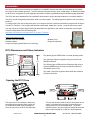
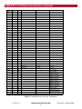
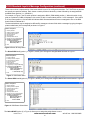
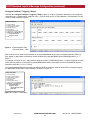
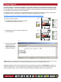
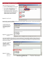
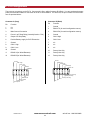
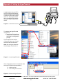
GENERIC
CANbus Setup / Configuration
Manual
R170 Receiver
Revised May 17, 2006
Version 3
DMAN - 2866 - 01
#74-1833 Coast Meridian Road, Port Coquitlam, BC, Canada • V3C 6G5
Ph# (604) 944-9247 • Fax# (604) 944-9267
Toll Free 1-800-663-8806
DMAN-xxxx-xx
www.omnexcontrols.com
1
call toll free: 1-800-663-8806
Table of Contents
1.
Introduction................................................................................................................................... 3
2.
J1939 Setup ................................................................................................................................. 4
3.
OMNEX R170 J1939 Data Frame Structure ................................................................................ 5
4.
J1939 Standard Joystick Message Configuration ........................................................................ 7
5.
Firmware Upgrade...................................................................................................................... 12
6.
R170 Pin Assignments ............................................................................................................... 14
7.
Appendix A: Setting Up HyperTerminal...................................................................................... 15
8.
Appendix B: BJM Button Menus................................................................................................. 17
9.
Appendix C: BJM Position Menus .............................................................................................. 18
Safety Precautions
NOTE: These instructions are intended only for configuring the remote control equipment described here. This is not a complete Operator’s Manual. For complete operating instructions, please read the Operator’s Manual appropriate for your particular machine.
READ ALL INSTRUCTIONS
CAUTION: Changes or modifications not expressly approved by the party responsible for compliance could void the
user's authority to operate the equipment.
Failure to follow the SAFETY PRECAUTIONS may result in radio equipment failure and serious personal injury.
Installation
PROVIDE A SAFETY CUTOFF SWITCH. If maintenance is required, the radio must be disconnected from power .
USE PROPER WIRING. Loose or frayed wires can cause system failure, intermittent operation, machine damage, etc.
DO NOT INSTALL IN HOT AREAS. This apparatus can be damaged by heat in excess of 158° F (70° C).
Personal Safety
MAKE SURE MACHINERY AND SURROUNDING AREA IS CLEAR BEFORE OPERATING. Do not activate the remote system unless it is safe to do so.
TURN THE RECEIVER POWER OFF BEFORE WORKING ON MACHINERY. Always disconnect the remote system
before doing any maintenance to prevent accidental operation of the machine.
Care
KEEP DRY. Do not clean the transmitter / receiver under high pressure. If water or other liquids get inside the transmitter battery or receiver compartment, immediately dry the unit. Remove the case and let the unit air dry.
CLEAN THE UNIT AFTER OPERATION. Remove any mud, dirt, concrete, etc. from the unit to prevent clogging of buttons, switches, etc. by using a damp cloth.
Maintenance / Welding
DISCONNECT THE RADIO RECEIVER BEFORE WELDING on the machine the radio is connected to. Failure to disconnect will result in the destruction of the radio receiver.
DMAN-xxxx-xx
www.omnexcontrols.com
2
call toll free: 1-800-663-8806
Introduction
The R170 is a radio receiver that takes commands from an OMNEX wireless transmitter and translates the commands
into J1939 or other CANbus protocols. The R170 has two CAN ports and can act as a CAN bridge. An RS232 port allows
the R170 to be configurable, provide diagnostic information, firmware upgradeable and provides data logging capabilities.
The R170 also has a dedicated EN-418 compliant E-Stop system to ensure the safe shutdown of a controlled machine.
The R170 must be configured properly when used in a control system. The following sections describe how to configure
the R170.
To configure the R170 connect the serial port to your computer and use a serial communications program such as HyperTerminal1 or TeraTerm. The program should be set to 9600 baud, 8 data bits, no parity, 1 stop bit and no flow control.
You may choose to configure HyperTerminal as described in the Appendix of this manual or download pre-set HyperTerminal configurations from the following URL:
http://www.omnexcontrols.com/Support/R170_Support_Files.aspx
Other R170 features include:
900 MHz & 2.4 GHz available
Pendant Capable
Frequency Hopping Spread Spectrum Technology
Weather Proof
Diagnostic Indicators
R170 Receiver
R170 Dimensions and Status Indicators
STATUS
The (Status) light is GREEN when in normal operating mode.
LINK
ESTOP
5.13”
CAN 1
CAN 2
The (Link) light indicates a signal is being received from an
OMNEX transmitter.
The (E-Stop) light is RED when the Emergency-Stop relay is
open and GREEN when the relay is closed (the machine is
controllable by the R170).
A
The (CAN 1) and (CAN 2) lights indicate when the respective
CAN ports are active.
B
4.00”
Opening the R170 Case
SW 1
The cap on the R170 enclosure is held on by
two plastic tabs at opposing sides, which can
be unlatched as shown using a screwdriver.
Once the cap is free, the R170 can slide open.
DMAN-xxxx-xx
SW 2
The two push buttons inside the R170’s front panel can be
used in conjunction with the HyperTerminal interface to
configure the R170 for desired operation. The button
marked as [SW 1] is used for general configuration and the
button marked as [SW 2] is used for CAN configuration.
www.omnexcontrols.com
3
call toll free: 1-800-663-8806
J1939 Setup
The R170 uses J1939 over CAN bus to communicate with the other devices in the system. Certain J1939 specific
parameters may be configured by the user by entering the J1939 CANBUS Setup Mode. To enter J1939 CANBUS
Setup Mode, proceed as follows:
NOTE: Connect the R170 to the PC via a serial cable and program using HyperTerminal—Refer to Appendix C for details
A. Press and hold [SW 2] on the
R170’s front panel. The (Status)
and (CAN 1) lights will flash
GREEN slowly.
A
STATUS
SW 2
B. Continue to hold [SW 2] until the
(Status) and (CAN 1) lights begin to
flash GREEN quickly (5 seconds).
C. When this occurs, release the button
to enter J1939 CANBUS Setup Mode.
D. If the [SW2] button is held for more
than 10 seconds, the (Status) and
(Link) LED indicators will flash RED
quickly.
C
STATUS
LINK
LINK
ESTOP
ESTOP
CAN 1
CAN 1
CAN 2
CAN 2
STATUS
SW 2
B
D
STATUS
LINK
LINK
ESTOP
ESTOP
CAN 1
CAN 2
CAN 1
CAN 2
A menu will be displayed in your communications program as shown below.
NOTE: this menu may be different
depending on the firmware option
provided with your unit.
Figure 1: CANbus Setup Menu
You may set the R170’s J1939 Primary Address using option 1 in the menu. The default primary address is 128,
which corresponds to the J1939 OEM address.
As shown in Table 1, the following fields can be defined by the user using the CAN setup menu:
•
Arbitrary Address Capable (option 2)
•
Vehicle System Instance (option 3)
•
Function Instance (option 4) and
•
ECU Instance (option 5)
Light Legend
Solid
DMAN-xxxx-xx
Slow
Flash
Fast
Flash
Red
Light
Green
Light
www.omnexcontrols.com
4
Yellow
Light
Alternating Red
& Green Light
call toll free: 1-800-663-8806
J1939 Setup (continued)
Use option 6 in Figure 1 to set the PGN Repetition Interval which is described in more detail in the section—J1939 Data
Frame Structure
Use the Toggle Proprietary or Joystick Messages (BJM/EJM), option 7, to toggle the type of messages transmitted by
R170. The R170 can transmit either Proprietary messages, as described in section—J1939 Data Frame Structure, or
SAE J1939-71 Joystick messages, as described in the SAE document Vehicle Application Layer – J1939-71 (through
2001), Revised 2003-12.
If the R170 is configured to transmit SAE joystick messages then use Configure Joystick Messages (option 8) to configure the mapping of OMNEX analog and switch/button values to joystick message fields.
NOTE: You must set the transmitter ID before configuring the mapping (see section Downloading Transmitter ID in the User’s Manual).
The other items in the menu affect the R170’s J1939 NAME on the J1939 network. A J1939 node name is 8 bytes long
and in the R170 is defined as shown in Table 1.
Each node on a J1939 network must have a unique name. To facilitate this, the R170’s J1939 name is dependent on
the transmitter ID downloaded from an OMNEX wireless transmitter. The transmitter ID is labeled on the OMNEX transmitter.
When the J1939 CANBUS Setup Mode is exited, the R170 will re-initialize with the new J1939 NAME and continue
normal operation.
Name Field
Arbitrary Address Industry
Capable
Group
Vehicle Systems Vehicle
Instance
System
Reserved Function
Function
Instance
ECU
Instance
Manufacturer
Code
Identity Number
Number of bits
1 bit
3 bits
4 bits
7 bits
1 bit
8 bits
5 bits
3 bits
11 bits
5 bits
Defined by
User
OMNEX
User
OMNEX
SAE
OMNEX
User
User
OMNEX
OMNEX OMNEX Transmitter
Default value
1
0
0
0
0
52
0
0
129
0
R170 ID Transmitter ID
16 bits
N/A
Table 1 R170 J1939 NAME Fields
OMNEX R170 J1939 Data Frame Structure
In proprietary message mode, the R170’s J1939 interface (CAN1) cyclically outputs PDU2 frames containing the OMNEX
command values from an OMNEX transmitter. Table 2 shows the contents of each frame. The default transmission period is 10 milliseconds but this may be changed via the J1939 CANbus Setup Menu.
NOTE: There may be other devices in a J1939 network, which use PGN 65280. Therefore, ECUs should match the SA to entries in
its NAME table to ascertain whether a particular PGN 65280 frame originates from an OMNEX R170. The NAME of the R170 is given
in Table 1.
PGN
65280
65281
Byte
Bit
T110 Content
T150 Content
Trigger Analog
T300 Content
0
NA
1
NA
Paddle 2 Analog
Paddle 1 Analog
2
NA
Paddle 3 Analog
3
NA
Paddle 4 Analog
4
NA
Paddle 5 Analog
5
NA
Paddle 6 Analog
6
NA
Paddle 7 Analog
7
NA
Paddle 8 Analog
0
NA
Potentiometer 1
1
NA
Potentiometer 2
2
NA
3
NA
Table 2 PGN Definition for the Origa Transmitters
DMAN-xxxx-xx
www.omnexcontrols.com
5
call toll free: 1-800-663-8806
OMNEX R170 J1939 Data Frame Structure (continued)
PGN
Byte
Bit
65281
4
7
4
6
4
5
4
4
4
3
4
2
65282
T110 Content
T150 Content
T300 Content
E-Stop
E-Stop
4
1
E-Stop
4
0
On Button
5
7
Button 8
SW 2 DN
SW 5 DN
5
6
Button 7
SW 2 UP
SW 5 UP
5
5
Button 6
SW 3 DN
SW 6 DN
5
4
Button 5
SW 3 UP
SW 6 UP
5
3
Button 4
SW 4 DN
SW 7 DN
5
2
Button 3
SW 4 UP
SW 7 UP
5
1
Button 2
SW 6 DN
SW 8 DN
5
0
Button 1
SW 6 UP
SW 8 UP
6
7
Auxiliary Button 16
6
6
Auxiliary Button 15
6
5
Auxiliary Button 14
6
4
Auxiliary Button 13
6
3
Auxiliary Button 12
6
2
Auxiliary Button 11
6
1
Auxiliary SW 4
Power Switch
6
0
Auxiliary SW 3
7
7
Auxiliary SW 2
7
6
7
5
SW 7 DN
SW 2 DN
7
4
SW 7 UP
SW 2 UP
7
3
SW 5 DN
SW 3 DN
7
2
SW 5 UP
SW 3 UP
7
1
Button 10
SW 1 DN
SW 4 DN
7
0
Button 9
SW 1 UP
SW 4 UP
0
NA
Set 5 low Byte
1
NA
Set 5 high Byte
2
7
Paddle 8 center off
6
Paddle 7 center off
5
Paddle 6 center off
Auxiliary SW 1
4
Paddle 5 center off
3
Paddle 4 center off
2
Paddle 3 center off
1
Paddle 2 center off
0
Paddle 1 center off
3
NA
Set 6 high Byte
4
NA
Setup data low byte
5
NA
Setup data high Byte
Table 2 PGN Definition for the Origa Transmitters
DMAN-xxxx-xx
www.omnexcontrols.com
6
call toll free: 1-800-663-8806
J1939 Standard Joystick Message Configuration
The SAE document Vehicle Application Layer – J1939-71 (through 2001), Revised 2003-12 defines six joystick messages: three basic joystick messages (BJM) and three extended joystick messages (EJM). Each BJM provides fields for
two axes (x and y) and twelve buttons. Each EJM provides fields for three axes (x-grip, y-grip and theta). EJM messages
do not support buttons.
Selecting Configure Joystick Message (option 8) from the main menu displays the menu shown in Figure 2
CANbus Setup Menu:
1—Primary Address
2—Arbitrary Address Capable
3—Vehicle System Instance
4—Function Instance
5—ECU Instance
6—PGN Repetition Interval
7—Toggle Prop. Or Joystick Message
8—Configure Joystick Message
0—Exit
Figure 2: Basic/Extended Joystick
Message Setup Menu
Transmit Enable / Disable
Transmit Enable/Disable (option 1) allows you to enable/disable transmission of the six messages individually as
shown in Figure 3.
CANbus Setup Menu:
1—Primary Address
2—Arbitrary Address Capable
3—Vehicle System Instance
4—Function Instance
5—ECU Instance
6—PGN Repetition Interval
7—Toggle Prop. Or Joystick Message
8—Configure Joystick Message
1—Transmit Enable/Disable
0—Exit
Figure 3: BJM/EJM Transmit Enable/Disable Setup Menu
DMAN-xxxx-xx
www.omnexcontrols.com
7
call toll free: 1-800-663-8806
J1939 Standard Joystick Message Configuration (continued)
Position Status Enable / Disable
Position Status Enable/Disable (option 2), in Figure 1, allows you to configure the status fields as shown in Figure 4
CANbus Setup Menu:
1—Primary Address
2—Arbitrary Address Capable
3—Vehicle System Instance
4—Function Instance
5—ECU Instance
6—PGN Repetition Interval
7—Toggle Prop. Or Joystick Message
8—Configure Joystick Message
2—Position Status Enable/Disable
0—Exit
Figure 4: BJM/EJM Position Status
Enable/Disable Setup
Menu
The Toggle Paddle/Joystick Axis Neut/Pos/Neg Position Status (option 1), in Figure 4, toggles the meaning of the
neutral, positive and negative position status fields in the BJ and EJ messages. If they are enabled then these fields are
set according to the positions of the joysticks, paddles or dials.
For example, if a joystick is in its neutral position then the corresponding neutral position status field within the BJM or
EJM will indicate 0b01 (2-bit binary value) and the positive and negative position status fields will indicate 0b00. If the
joystick is positive of center then corresponding positive position status field will indicate 0b01 and the neutral and negative position status fields will indicate 0b00. Similarly, if the joystick is negative of center then the corresponding negative
position status field will indicate 0b01 and the neutral and positive position status fields will indicate 0b00. If the position
status fields are disabled then they will all indicate values of 0b11.
The Toggle Paddle/Joystick Fullscale (option 2), in Figure 4, toggles the scaling of the x, y, x-grip, y-grip and theta
position fields in the BJ and EJ messages. If enabled, the OMNEX analog values will be scaled to fill the entire 10-bit
fields of the BJ and EJ messages. If disabled, the 8-bit OMNEX analog values will be transmitted.
Configure Switches
Selecting the Configure Switches (option 3), in Figure 2, displays a representative “graphical” menu depending on the
configured transmitter type, allows transmitter switches to be “re-mapped” to different BJM message. Figure 5 shows the
graphical menu for a T300 transmitter. See Appendix B for the menus of other transmitter models.
CANbus Setup Menu:
1—Primary Address
2—Arbitrary Address Capable
3—Vehicle System Instance
4—Function Instance
5—ECU Instance
6—PGN Repetition Interval
7—Toggle Prop. Or Joystick Message
8—Configure Joystick Message
3—Configure Switches
0—Exit
Figure 5: BJM Button Setup
Menu – T300
DMAN-xxxx-xx
www.omnexcontrols.com
8
call toll free: 1-800-663-8806
J1939 Standard Joystick Message Configuration (continued)
These menus show a representation of the button/switch layout of the configured transmitter. For T150/T300, the buttons
are actually two-position switches. Each button or switch position is labeled by a letter followed by the assigned BJM
and BJM button position (i.e., A-BJM1.01).
For example, in Figure 5, the ‘B’ switch position is assigned to BJM 2 (PGN 64984) position 1. When this switch is toggled on to position B, BJM2 will indicate it with a value of 0b01 in button status position 1 of BJ message 2. If the switch
is off, the button position 1 field of BJM2 will indicate 0b00. Buttons/switches that are not assigned to one of the BJM
button fields will indicate 0b11.
The buttons/switches may be assigned to different BJ messages or button fields within a message by typing the appropriate number/letter (in this example B) as shown in Figure 6
CANbus Setup Menu:
1—Primary Address
2—Arbitrary Address Capable
3—Vehicle System Instance
4—Function Instance
5—ECU Instance
6—PGN Repetition Interval
7—Toggle Prop. Or Joystick Message
8—Configure Joystick Message
3—Configure Switches
Basic Joystick Message
Button Setup Menu
0—Exit
Figure 6 Button B Setup Menu
The Select BJM 1 to 3 (option 1), in Figure 6, allows you to change the assigned BJM as shown in Figure 7.
CANbus Setup Menu:
1—Primary Address
2—Arbitrary Address Capable
3—Vehicle System Instance
4—Function Instance
5—ECU Instance
6—PGN Repetition Interval
7—Toggle Prop. Or Joystick Message
8—Configure Joystick Message
3—Configure Switches
Basic Joystick Message
Button Setup Menu
1—Select BJM (1 to 3)
0—Exit
Figure 7: BJM Select Menu
The Select BJM 1 to 12 (option 2), in Figure 6, allows you to change the assigned BJM button field as shown in Figure 8.
CANbus Setup Menu:
1—Primary Address
2—Arbitrary Address Capable
3—Vehicle System Instance
4—Function Instance
5—ECU Instance
6—PGN Repetition Interval
7—Toggle Prop. Or Joystick Message
8—Configure Joystick Message
3—Configure Switches
Basic Joystick Message
Button Setup Menu
3—Select NONE
0—Exit
Figure 8: BJM Button Select Menu
The Select NONE (option 3), in Figure 6, allows you to assign the switch/button to none.
DMAN-xxxx-xx
www.omnexcontrols.com
9
call toll free: 1-800-663-8806
J1939 Standard Joystick Message Configuration (continued)
Configure Paddle(s) / Trigger(s) / Dial(s)
Selecting the Configure Paddle(s) / Trigger(s) / Dial(s) (option 4), in Figure 2, displays, depending on the configured
transmitter type, a representative “graphical” menu. Figure 9 shows one for a T300 transmitter. See Appendix C for the
menus of other transmitter models.
CANbus Setup Menu:
1—Primary Address
2—Arbitrary Address Capable
3—Vehicle System Instance
4—Function Instance
5—ECU Instance
6—PGN Repetition Interval
7—Toggle Prop. Or Joystick Message
8—Configure Joystick Message
4—Configure Paddle(s) /
Trigger(s) / Dial(s)
0—Exit
Figure 9: Joystick Message Position Setup Menu – T300
Each of these menus shows a representation of the joystick/paddle/dial layout of the configured transmitter. Each joystick, paddle, or dial position is labeled by a letter followed by the assigned BJM/EJM and BJM/EJM position (i.e., 1BJM1.1).
For example, in Figure 18, the ‘1’ dial position is assigned to BJM 1 (PGN 64982) position 1. BJM1 will indicate the value
of this dial in its position 1 (x-axis) field. Joysticks/paddles/dials that are not assigned to one of the BJM/EJM position
fields will indicate 0b1111111111 (10-bit).
The joysticks/paddles/dials may be assigned to different BJ/EJ messages or position fields within a message by typing
the appropriate number/letter (in this example 1) as shown in Figure 10
CANbus Setup Menu:
1—Primary Address
2—Arbitrary Address Capable
3—Vehicle System Instance
4—Function Instance
5—ECU Instance
6—PGN Repetition Interval
7—Toggle Prop. Or Joystick Message
8—Configure Joystick Message
4—Configure Paddle(s) /
Trigger(s) / Dial(s)
Joystick Message Position
Setup Menu
0—Exit
Figure 10: Position 1 Setup Menu
DMAN-xxxx-xx
www.omnexcontrols.com
10
call toll free: 1-800-663-8806
J1939 Standard Joystick Message Configuration (continued)
The Select BJM/EJM 1 to 6 (option 1), in Figure 10, allows you to change the assigned BJM/EJM as shown in Figure
11.
CANbus Setup Menu:
1—Primary Address
2—Arbitrary Address Capable
3—Vehicle System Instance
4—Function Instance
5—ECU Instance
6—PGN Repetition Interval
7—Toggle Prop. Or Joystick Message
8—Configure Joystick Message
4—Configure Paddle(s) /
Trigger(s) / Dial(s)
Joystick Message Position
Setup Menu
1—Select BJM/EJM 1 to 6
0—Exit
Figure 11: BJM/EJM Select Menu
The Select BJM 1 to 2 / EJM 1 to 3 Position (option 2), in Figure 10, allows you to change the assigned BJM/EJM position field as shown in Figure 12.
CANbus Setup Menu:
1—Primary Address
2—Arbitrary Address Capable
3—Vehicle System Instance
4—Function Instance
5—ECU Instance
6—PGN Repetition Interval
7—Toggle Prop. Or Joystick Message
8—Configure Joystick Message
4—Configure Paddle(s) /
Trigger(s) / Dial(s)
Joystick Message Position
Setup Menu
2—Select BJM 1 to 2/EJM
1 to 3 Position
0—Exit
Figure 12: BJM/EJM Position
Select Menu
DMAN-xxxx-xx
www.omnexcontrols.com
11
call toll free: 1-800-663-8806
Firmware Upgrade
The R170 provides for in-field firmware upgrades. If an upgrade is necessary, a file containing the new firmware will be
provided by OMNEX. The firmware is upgraded using the R170’s serial interface and a serial communications program
such as HyperTerminal. The serial communication settings for firmware upgrades are different from the settings used in
the setup procedures described in the previous sections.
To upgrade the firmware, configure your communications program for 9600 baud, 8 data bits, no parity, 1 stop bit and
Xon/Xoff flow control. A HyperTerminal configuration file with these settings may be found at:
http://www.omnexcontrols.com/Support/downloads/R170/HyperTerminal/R170BootLoad.ht
A
To perform a firmware upgrade:
STATUS
A. first switch off the power to the R170. Press and
hold [SW 2] as you power on the R170
LINK
SW 2
Button
ESTOP
CAN 1
CAN 2
B
B. Release [SW 2] within 3 seconds of powering on
the R170 receiver.
STATUS
LINK
SW 2
Button
ESTOP
CAN 1
CAN 2
C
C. The R170 will enter Boot
loader Mode and displayed a menu on the
HyperTerminal screen
as shown in Figure 9.
NOTE: If [SW 2] is not released within 3 seconds of powering on the R170, the R170 assumes that [SW 2] is stuck and will not enter
Boot loader Mode; instead, it will start normal operation and display the initial power up message shown previously.
Optionally the baud rate of the R170’s serial interface may be changed, by choosing c) Set Baud Rate, to shorten the
firmware download time. If the R170’s baud rate is changed then the baud rate of your communications program must
also be changed to match. (Note: The R170’s baud rate will default to 9600 baud each time it is powered up.)
Light Legend
Solid
DMAN-xxxx-xx
Slow
Flash
Fast
Flash
Red
Light
Green
Light
www.omnexcontrols.com
12
Yellow
Light
Alternating Red
& Green Light
call toll free: 1-800-663-8806
Firmware Upgrade (continued)
Before downloading the new firmware:
A. Choose “a” Erase Flash to erase the flash.
C
B. Then to begin downloading the new firmware, choose “b” Program Flash,
C. Next perform a text/ASCII upload in your
communications program. If you are using
HyperTerminal, this is accomplished by
clicking Transfer and Send Text File in
HyperTerminal’s menu as illustrated.
A
B
Figure 13: Send Text File
Specify the file, provided by OMNEX, containing the firmware upgrade to send to the R170. The R170 will now begin to
receive and program the new firmware.
As the firmware is programming, asterisks will
be printed to the screen
indicating progress as
shown.
Figure 14: Finished Upgrading
Firmware
If your screen appears similar to the above, the new firmware has been successfully upgraded. Power cycle (turn off
then back on) the R170 to operate the R170 with the new firmware. Should errors be encountered during firmware upgrading, the firmware upgrade process will stop and an error message will be displayed on the HyperTerminal screen
similar to the one below.
In this case, try the procedure again, and call
OMNEX for technical
support should the problem persist.
Figure 15: Firmware
Upgrade Error
DMAN-xxxx-xx
www.omnexcontrols.com
13
call toll free: 1-800-663-8806
R170 Pin Assignments
There are two connectors on the R170. Connector A is Grey, while Connector B is Black. You can purchase the appropriate pre-terminated cables for connection to the R170 from OMNEX. For reference, the pin functions for both connectors are provided below:
Connector A (Grey)
Pin
Function
1
2
n/c
n/c
3
Connector B (Black)
Pin
Function
1
Ground
2
RS232 TX (for serial configuration menus)
Main Ground Connection
3
RS232 RX (for serial configuration menus)
4
Power in to E-Stop Relay (internally fused to 7.5A)
4
Ground
5
Output of E-Stop Relay
5
CAN 2 High
6
Positive Battery supply for R170 Electronics
6
CAN 2 Low
7
Ground
7
n/c
8
CAN 1 High
8
n/c
9
CAN 1 Low
9
n/c
10
Ground
10
Factory Use Only
11
RS485 A (for Wired Remotes)
11
Factory Use Only
12
RS485 B (for Wired Remotes)
12
Factory Use Only
Ground
RS232 TX
RS232 RX
Ground
CAN 2 High
CAN 2 Low
Ground
CAN 1 High
CAN 1 Low
Ground
RS485 A
RS485 B
7
6
8
5
1
7
9 10 11 12
4 3 2 1
2
8
3 4 5 6
9 10 11 12
Factory Use Only
Factory Use Only
Factory Use Only
n/c
n/c
Main Ground
E-Stop Power
E-Stop output
R170 power
DMAN-xxxx-xx
n/c
n/c
n/c
www.omnexcontrols.com
14
call toll free: 1-800-663-8806
Appendix A: Setting Up HyperTerminal
A serial interface from the R170
to a PC running a serial communications program such as HyperTerminal is required to configure
the R170. The program should
be set to 9600 baud, 8 data bits,
no parity, 1 stop bit and no flow
control.
C
Figure 16: Connect PC to R170
To create a new HyperTerminal
configuration:
A. launch HyperTerminal from
the Start menu shown below
and follow the configuration
prompts
Cal
The prompts will first ask for a
Connection Name, your Country,
Area Code and Line Access #.
Note: this will only be asked the
first time Hyper Terminal is run.
Figure 17: Launch HyperTerminal
Once the prompts have been completed, make
sure HyperTerminal is disconnected by:
A
A. clicking on Call
B. then clicking on Disconnect.
B
Figure 18: Disconnect HyperTerminal
1
HyperTerminal is developed by Hilgraeve Inc. for Microsoft®, and comes bundled with the Microsoft Windows operating system.
DMAN-xxxx-xx
www.omnexcontrols.com
15
call toll free: 1-800-663-8806
Appendix A: Setting Up HyperTerminal (continued)
Next, ensure that “Echo characters typed locally” (in Settings, ASCII Setup) is disabled.
A
To do this:
A. open the Properties window by clicking the
Properties menu item under the File menu
B. next, click on Settings and then ASCII
Setup
C. once “Echo characters typed locally” is
disabled, click OK
B
C
Figure 19: Disable Echo Characters Typed
Locally
After the serial interface is connected and your serial communications program is running, you will be able to configure
the R170 using HyperTerminal and the SW1 and SW2 buttons located on the circuit board panel of the R170.
To configure the R170:
A. go to the Configuration by clicking on the
Connect To tab
B. then in the Properties window click the Configure button to open the Configuration window
C. make the appropriate changes (9600 baud,
8 data bits, no parity, 1 stop bit and no flow
control), as shown.
A
C
B
Figure 20: Configure R170
A HyperTerminal configuration file with the settings shown above may be found at:
http://www.omnexcontrols.com/Support/R170_Support_Files.aspx then click on R170 Conf link
DMAN-xxxx-xx
www.omnexcontrols.com
16
call toll free: 1-800-663-8806
Appendix B: BJM Button Menus
Figure 21: BJM Button Setup
Menu – T100
Figure 22: BJM Button Setup
Menu – T110
Figure 23: BJM Button Setup
Menu – T150
Figure 24: BJM Button Setup
Menu – T300
DMAN-xxxx-xx
www.omnexcontrols.com
17
call toll free: 1-800-663-8806
Appendix C: BJM Position Menus
Figure 25: BJM Joystick Message Position
Setup Menu – T150
Figure 26: BJM Joystick Message Position
Setup Menu – T300
DMAN-xxxx-xx
www.omnexcontrols.com
18
call toll free: 1-800-663-8806