1
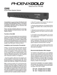
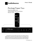
USER MANUAL DV-MFSW-94 9x4 PRESENTATION MATRIX SWITCHER 244 Bergen Boulevard, Woodland Park, NJ 07424 Tel 973-785-4347 FAX 973-785-3318 Web www.fsrinc.com LIT1376 1 Proprietary Information All information in this manual is proprietary to and the property of FSR Inc. This publication is protected by the Federal Copyright Law, with all rights reserved. No part of this document may be reproduced, transcribed, or transmitted, in any form or by any means, without prior explicit written permission from FSR Inc. Unpacking The DV-MFSW-94 9x4 PRESENTATION MATRIX SWITCHER package includes the following items; DV-MFSW-94 9x4 PRESENTATION MATRIX SWITCHER 12VDC Power Supply with AC cord USB-A to USB mini-B cable RJ-45 to RJ-45 straight through cable DB-9 Male to DB-9 Female Set of Rack Mounting Ears with Hardware Two 5-position Screw Down Terminal Plugs User manual x 1 Cautions: 1. FSR logo is a trademark of FSR Inc. 2. HDMI is a trademark of HDMI licensing, LLC. 3. Specification may be changed without any notice in order to improve the function of the product. 4. The design and specification of the product may be change without any prior notice. 2 Table of Contents 1 PROPRIETARY INFORMATION................................................................................................................ 2 1.1 SAFETY.......................................................................................................................................... 4 1.2 FEATURES..................................................................................................................................... 5 1.3 FRONT PANEL............................................................................................................................... 6 1.4 REAR PANEL ................................................................................................................................. 6 2 ENVIRONMENTAL .................................................................................................................................... 7 3 FUNCTIONS OF THE PRODUCT ............................................................................................................. 7 3.1 FEATURES OF PRODUCT .................................................................................................................... 7 3.2 SYSTEM OPERATION AND CONFIGURATION DIAGRAM .......................................................................... 7 3.3 SPECIFICATIONS................................................................................................................................ 8 4 OPERATION .............................................................................................................................................. 9 5 RS-232 PROTOCOL ................................................................................................................................ 12 6 5.1 GENERAL NOTES ............................................................................................................................ 12 5.2 REQUEST/RESPONSE FORMAT......................................................................................................... 12 5.3 COMMAND REQUEST SYNTAX:......................................................................................................... 12 5.4 ACKNOWLEDGING RECEIPT OF COMMANDS...................................................................................... 12 5.5 ERROR RESPONSE .......................................................................................................................... 12 COMMAND LIST:..................................................................................................................................... 13 6.1 SET CON COMMAND ...................................................................................................................... 13 6.2 SET HDMI AUDIO OUTPUT COMMAND .............................................................................................. 14 6.3 SET HDMI EDID ............................................................................................................................ 14 6.4 SET INPUT SOURCE COMMAND ........................................................................................................ 15 6.5 SET STEREO AUDIO OUTPUT COMMAND ........................................................................................... 15 6.6 SET PRESET RECALL COMMAND ...................................................................................................... 16 6.7 RESET DV-MFSW-94..................................................................................................................... 16 6.8 SET SERIAL BAUD RATE ................................................................................................................. 16 6.9 SET IP ADDRESS ............................................................................................................................ 17 6.10 GET UNIVERSAL STATUS COMMAND ................................................................................................ 17 6.11 GET OUTPUT CONNECTION STATUS ................................................................................................. 17 6.12 GET INPUT ASSIGNMENT STATUS ..................................................................................................... 18 6.13 GET AUDIO OUTPUT STATUS ........................................................................................................... 18 6.14 INPUT OR OUTPUT TIMING STATUS .................................................................................................. 19 6.15 RS232 SETTINGS ........................................................................................................................... 19 6.16 LAN SETTINGS ............................................................................................................................... 20 7 DV-MFSW-94 IP CONTROL .................................................................................................................... 21 8 FIRMWARE UPGRADE INSTRUCTIONS............................................................................................... 24 9 LIMITED WARRANTY ............................................................................................................................. 27 3 1.1 Safety instructions and user manual should be read before the device is operated. This product should be operated only from the type of power sources indicated on the label. If you are not sure of the type of power supplied to your facility, consult your local power company. For equipment intended to operate from battery power, or other source, refer to the user manual. This equipment may be equipped with a 3-wire grounding-type plug, a plug having a third (grounding) pin. This pin will only fit in to a grounding type power outlet. This is a safety feature. If you are unable to insert the plug in to the outlet, contact your electrician to replace your obsolete outlet. Do not defeat the safety purpose of the grounding-type plug. Openings in the cabinet are provided for ventilation, to ensure reliable operation of the equipment and to protect it from overheating. The openings should never be blocked. 4 SAFETY Safety and operating instructions should be retained for future reference. Unplug this product from the wall outlet before cleaning. Do not use liquid cleaners or aerosol cleaners. Use a damp cloth for cleaning. Do not use damaged power cords or plugs or loose outlets. This may cause electrical shock or fire. Do not stack heavy articles such as other equipment on this product. Keep this device away from liquid, magnetic, inflammable substances. Turn off power before connecting or disconnecting cables. 1.2 FEATURES The Hybrid Presentation Matrix DV-MFSW-94 supports VGA, HDMI, DVI, YPbPr, S-Video and CVBS signals. Signals from any of up to 9 sources can be sent simultaneously to as many as 4 HDMI or DVI displays. HDCP (High-bandwidth Digital Content Protection) is supported from all digital sources to all outputs. Complies with DVI V1.0 and HDMI V1.3 standards 19” standard rack type case (3U) Supports fiber optic and UTP transmitters for accessing sources at a distance from the unit. Provides complete EDID management including more than 25 pre-programmed combinations and the ability to learn new and non-standard EDID data sets. Provides up to 20 switch program presets HDCP (High-bandwidth Digital Content Protection) compliance for all output channels Enhanced quality and color of digital signals Supporting Functions: Supports high resolution up to WUXGA(1920x1200), 480p~1080p LCD status and setup window on the front panel Control through: • Front panel menu and display • Control method through RS-232C COM port and TCP/IP • Web server thru LAN (TCP/IP) Electronic anomaly suppression circuitry protects the DV-MFSW-94 as well as connected devices. 5 1.3 FRONT PANEL The functions of the switches are as follow. 1.4 Main power switch: Matrix power on/off Menu Button: Access Main Menu Arrows: Selecting the available functions. Enter key: save current selection Cancel key: cancel current selection REAR PANEL 6 +12V DC: DC power +12V input port SP: Service Port (Upgrade Firmware thru USB) LAN: LAN (TCP/IP) RS-232: RS-232C communication input port Digital Video Inputs 1-4: HDMI with external Stereo Audio Digital Video Inputs 5-7: CAT or Fiber Optic Analog Video Inputs 8-9: RGB/YPbPr, CVBA, S-Video and Stereo Audio Balanced Audio Inputs CH 1-2: Balanced Audio Audio Out: Stereo Audio Output OUTPUTS: DVI/HDMI & SPDIF Audio Outputs (OUTPUT 1~4) 2 Environmental For installation, we recommend the following environments. Below 85 F (30°C) of ambient temperature (Best condition) Install and operate in the environment below 60% of ambient humidity (Best condition) Use it in the environment of free of vibrations and dusts and in good ventilation condition Recommend stabilized AC input power (Recommend to use AVR) 3 3.1 Functions of the product Features of Product The DV-MFSW-94 is a Hybrid matrix router that allows both analog and digital video sources to be reliably routed to as many as four digital displays. The DV-MFSW-94 will adjust the output signals to the optimal resolution for the connected display device. Please find below block diagram for better understanding. Input signals can be selected for each output port by RS-232C, LAN (TCP/IP) or front panel menu. 3.2 System Operation and Configuration Diagram 7 3.3 Specifications Input 1. 9 CH Sources 2. DVI/ HDMI Inputs (Input 1 – 4) - Resolutions: PC (up to WUXGA), HDTV (up to 1080p) - DVI 1.0 / HDMI 1.3v, HDCP - Stereo Audio Max 1Vrms 3. CAT / Fiber Optical Inputs (Input 5-7) - Resolutions: PC (up to WUXGA), HDTV (up to 1080p) - HDMI 1.3v, HDCP - CAT (Max 50m) - 2 Core Optical (Multi, Single Mode Fiber Optic Cable) 4. Analog Inputs (Input 8-9) - 12-bit 170 MSPS ADC - VGA to WUXGA and 1080p / 60Hz - Signal Format: RGB, YPbPr, CVBS, S-Video - Supporting Resolutions: RGB (up to WUXGA), YPbPr (480p – 1080p), CVBS / S-Video (NTSC / PAL) 5. 2 CH Balanced Audio Inputs: - Route to stereo audio output or embed in HDMI output Signals Output 1. 4 CH HDMI/DVI Outputs 2. Scaled Outputs: Outputs digital video perfectly scaled for each connected display device. - Resolutions: PC (up to WUXGA), HDTV (up to 1080p) - Image Freeze 3. Optical Toslink, COAXIAL SPDiF Digital Audio 4. Stereo Audio Max 1Vrms Output (RCA) Control 1. RS-232C 9600 – 115200 Bps 2. LAN, TCP/IP TELNET Power: DC-12V, 6.6A, 25Watt / 35 Watt Dimensions: 17.126” W X 10.630”D X 3.465” H (435mm W X 270mm D X 88mm H) (3RU) Weight: 15.76 lb. (7.15 Kg) 8 4 Operation 1. MAIN MENU * OUTPUT INFO VIEW * [ OutPut: 1 2 3 4 ] [ Input : 1 4 7 9 ] [ 1920 x 1080p 60 ] Displays the timing (Resolutions) information of Inputs and Outputs to output Displays the timing (Resolutions) information of each output channels using Left/Right arrow buttons. 2. MENU LIST →1.OUTPUT CREATE 2.INPUT CONFIG 3.OUTPUT TIMING SET 4.OUTPUT AUDIO SET →5.STEREO AUDIO SET 6.PRESET 7.PROGDUCT ID 8.RS232C CONFIG →9. LAN CONFIG 10. INPUT EDID SET 11.INPUT INFO 12.SOFTWAREUPGRADE Press Menu button to get the list of Menus. Select the function using UP/Down buttons Press Enter button to go into more detail set up of the selected function. 3. OUTPUT CREATE SETUP -OUTPUT CREATE MODE[ OutPut: 1 2 3 4 ] [ InPut : 1 4 7 9 ] [ HDMI/DVI & AUDIO ] This section is to route Input Channels to outputs. Select Output Channel using Left/Right buttons. Select Input Channel using Up/Down button, and press Enter button to save. Will display Input Config and Output Audio Config according to above channel selection. 4. INPUT CONFIG SETUP This section is for setting up input configurations: Selecting Audio sources thru input Channel 1 – 4 0: Auto Audio – Automatically detects audio input 1: HDMI Audio – HDMI Source Audio. 2: STEREO Audio – External Input Audio. Selecting Video sources thru Input Channel 5 – 7 0: CAT-X IN 1: FIBER IN SET Select Analog video sources thru Input Channel 8 – 9 0: VGA 1: YPbPr 2: CVBS 3: S-Video Select the input channel using Left / Right buttons. Select the source using up / down button, and press enter button to save. -INPUT CONFIG SETUP[ 1 2 3 4 →] [ 2 0 1 2 ] [ 2:Stereo Audio ] 5. OUTPUT TIMING SETUP - OUTPUT TIMING [OutCH: 1 2 3 4 ] [TimNo: 0 2 2 1 ] [ Auto Time Set ] This section is for setting up Output Channel Timing (Resolutions): Selecting the output channel using the Left / Right buttons. Select the timing number using the up / down buttons, and press enter button to save. ※ Auto Time Set – CR94 read display such as TV, monitors EDID (if no picture, select default setting; 720p1080i) 9 6. PRESET Selecting PRESET call/edit using up / down buttons. - PRESET 1.PRESET Call 2.PRESET EdIt - PRESET CALL - PRESET Call Call Num : 1 - PRESET Edit Edit Num : 1 Select call number using up / down buttons, and press enter button. Will display PRESET VIEW on display. - PRESET EDIT Select the preset number using Left / Right buttons, and press enter button. Change the configuration using up / down buttons, and press enter to save. - PRESET 1 Edit Output No : 1 InP No : InPS : Out Tim : Aud : 7. AUDIO OUTPUT SETUP - PRESET 1.PRESET Call 2.PRESET EdIt 8. STEREO AUDIO OUTPUT SETUP - STEREO AUDIO OUT ] [Audio In: 11 [ Balance Audio 2 ] [ Change:Up/Down ] This Section is for setting up the output channel audio. 0:Source Audio 1:Balance Audio 1 2:Balance Audio 2 Selecting output channel using Left / Right buttons. Select audio source using up / down buttons, press enter to save. This section is for setting up the Stereo Audio Output Source. 0 - 9: Input Channel Source Audio 1: Balance Audio 1 2: Balance Audio 2 Select audio source using Up/Down button and press enter to save 9. PRODUCT ID SETUP - PRODUCT ID SETUP ] [ ID Data: 10 [ Edit:Up/Down ] [ Save:Enter ] 10 Select audio source using up / down buttons, and press enter to save. 10. RS232C CONFIG SETUP - RS232C CONFIG SET [ Baudreate: 57600_ ] [ Data Bit: 8 ] [ Parity: None ] Select menu using Left / Right buttons. Select data using up / down buttons. Press enter to save. Select menu using UP/Down buttons. Press enter to get into detail set up. 11. LAN CONFIG →1.LOCAL IP 2.GATEWAY IP 3.SUBNET MASK 4.MAC ADDRESS -LOCAL IP ADDRESS [ 192.168. 0. 2 ] [ ] [ Set & Save:Enter ] -GATEWAY ADDRESS [ 192.168. 0. 1 ] [ ] [ Set & Save:Enter ] - SUBNET MASK [ 255.255.255. 0 ] [ ] [ Set & Save:Enter ] - MAC ADDRESS [00.08.DC.00.01.00] [ ] [ Set & Save:Enter ] Set up using Left / Right buttons. Change the set up using up / down button. Press enter to save. 12. INPUT EDID DATA SET - INPUT EDID SETUP [ Input:1 HDMI/DVI ] [ EDID: 16 ] [ HD1080p (2CH) ] Select menu using Left / Right buttons. Select input channel and EDID data using up / down buttons. Press Enter to save. 13. INFO - INPUT1 INFO VIEW [IN1:HDMI,Ext-SPDIF] [TIM: NO SIGNAL ] [DVI MODE HDCP OFF] Select channel to review the information using Left / Right buttons. 11 5 RS-232 Protocol 5.1 General Notes This document describes the protocol for interfacing with the DV-MFSW-94. 5.2 Request/Response Format All requests and responses will be entirely in ASCII. This will make the DV-MFSW-94 easy to use. All commands and input parameters are in upper case only. All requests are terminated with a carriage return (0Dh), which will be referred to in this document as <cr>. All responses are terminated with a carriage return <cr> and a line feed (0Ah). A line feed will be represented in text below as <lf>. 5.3 Command Request Syntax: This document uses the following notation when describing the syntax of a command request: BOLD – identifies the command lower case – italicized identifies data to be entered which is described in the text following the syntax description ““ - entry defined within double quotes is to be entered exactly as shown. [ ] - entry defined within these brackets is optional and may occur one or more times. 5.4 Acknowledging Receipt of Commands Each request sent to the Pathfinder Matrix will have by default two possible responses, an acknowledgement of a correct request or an error response. The acknowledge response will be: Ok<cr><lf>. 5.5 Error Response It is perhaps inevitable that errors occur in the requests sent to the DV-MFSW-94. If an invalid command or text otherwise not representing a command is sent to the DV-MFSW-94, the unit will respond with the message “ERR: unknown command“. Example: A connect request with an incorrect output number, ie 5: CON 01 1(2,3,5) <cr> The error response would be: ERR: unknown command<cr><lf> Note that in the protocol descriptions to follow, syntax that can be repeated multiple times is represented in the notation X,,,,. This means entry of parameter X multiple times is entered as X, X, X, ie parameter X separated by “,” character, as many times as necessary (up to the limit of the command). Some commands allow configuration of multiple inputs or outputs without having to issue a separate command. The ‘;’ character is used to delineate each additional configuration, eg CON, HAU and HEDID commands. 12 6 Command List: CON Connect input to output(s) HAU HDMI Audio Output command HEDID HDMI EDID setting INSRC Input Source command SAO Stereo Audio Output command PRESET Preset Recall command RST Reset DV-MFSW-94 BAUD Sets the RS232 baud rate IPADR Sets the IP address STAT Universal Status command NOTE: All commands are terminated with a carriage return (0Dhex) represented by <cr> The default baud rate is 38400 bps. 6.1 Set CON Command Tells the DV-MFSW-94 which outputs to connect to which input CON id input “(“ output “,” output “,” ……”)”[“;” input”(“output,,,,”)”] <cr> WHERE: CON id input “(“ output 3 ASCII byte command name 2 byte unit ID An input number between 1 – 9 Parentheses indicating the start of the outputs to connect the input to. an output number 0 – 4 to connect to the input, zero representing no input. Multiple outputs can be included in the list separated by a comma. Parentheses to end the list of outputs Delimiter separating additional definitions Carriage Return (0Dhex) “)” “;” <cr> Example: Connect Unit 01 input 1 to outputs 2, 3 and 4 and input 2 to output 1. CON 01 1(2,3,4); 2(1)<cr> 13 6.2 Set HDMI Audio Output command Tells the unit which audio source to use for which output. HAU id output audiosource [“;” output audiosource]<cr> Where: HAU HDMI Audio Output Command id 2 byte unit ID output Output number 1-4, audiosource 2 byte audio source 00 = Source audio, 01 = Balance 1 Audio, 02 = Balance 2 Audio, 03 = Output Audio Off (Mute) Delimiter separating additional definitions <cr> Carriage Return (0Dhex) Example: Set Unit 01 Output 1 to Balance 1 Audio and Output 2 to Output Audio On. HAU 01 1 01; 2 04<cr> 6.3 Set HDMI EDID Tells the unit which timing scheme to use. HEDID id output setting[“;” output setting]<cr> HEDID HDMI EDID command id 2 byte unit ID output OUTPUT number 1 – 4 setting 00 - AUTO(EDID READ from display) 01 - represents 720x480p 02 - 720x576p 03 - 1280x720p 50Hz 04 - 1280x720p 60Hz, 05 - 1920x1080i 50Hz 06 - 1920x1080i 60Hz 07 - 1920x1080p 50Hz 08 - 1920x1080p 60Hz 09 - 800x600 60Hz 10 - 800x600 75Hz 11 - 1024x768 60Hz 12 - 1024x768 75Hz 13 - 1024x768 85Hz 14 - 1280x1024 60Hz 15 - 1280x1024 75Hz 16 - 1280x1024 85Hz 17 - 1600x1200 60Hz 18 - 1360x768 75Hz 19 - 1366x768 85Hz 20 - 1440x1050 60Hz 21 - 1900x1200 60Hz “;” Delimiter separating additional definitions <cr> Carriage Return (0Dhex) Example: Set Unit 01 Output 1 EDID to Auto, Output 2 to 1280x1024 85Hz. HEDID 01 1 00; 2 16<cr> 14 6.4 Set Input Source command Tells the unit which input source to use INSRC id input srcnum [“;” input srcnum]<cr> Where: INSRC Input source command name id 2 byte unit ID input Input number (1-9) srcnum Which input type to use, see table below: 00 01 02 03 “;” <cr> I01 I02 I03 I04 AUTO AUDIO HDMI AUDIO Ext. AUDIO AUTO AUDIO HDMI AUDIO Ext. AUDIO AUTO AUDIO HDMI AUDIO Ext. AUDIO AUTO AUDIO HDMI AUDIO Ext. AUDIO X X X X I05 I06 I07 I08 I09 CAT CAT CAT VGA VGA FIBER FIBER FIBER YPbPr YPbPr X X X CVBS CVBS X X X SVIDEO SVIDEO Delimiter separating additional definitions Carriage Return (0Dhex) Example: Set Unit 01 Input 9 to YpbPr, Input 1 to HDMI AUDIO. INSRC 01 9 01; 1 01<cr> 6.5 Set Stereo Audio Output command Tells the unit which input to direct to Stereo Audio Out. SAO id audioinput<cr> SAO Stereo Audio Output command id 2 byte unit ID audioinput 00 - Audio Open 01- 09 Assign HDMI Input1 Audio – HDMI Input9, Audio 10: Assign Balance Input1 Audio 11 : Assign Balance Input2 Audio <cr> Carriage Return (0Dhex) Example: Set Unit 01 HDMI Input 3 to Stereo Audio Out. SAO 01 03<cr> 15 6.6 Set Preset Recall command Tells the unit to recall the specified preset. PRESET id number<cr> PRESET Preset Recall command id 2 byte unit ID number Preset number to recall 01-20 <cr> Carriage Return (0Dhex) Example: Recall Unit 01 preset number 9. PRESET 01 09<cr> 6.7 Reset DV-MFSW-94 Resets the DV-MFSW-94 RST id<cr> RST Reset command name id 2 byte unit ID cr Carriage Return (0Dhex) Example Reset unit 1. RST 01<cr> 6.8 Set Serial Baud Rate Sets the baud rate of the RS232 port. BAUD id brate<cr> Where: BAUD Baud rate command id 2 byte unit ID brate Baud rate setting, 01 – 19200 bps 02 - 38400 bps 03 - 57600 bps 04 - 115200 bps <cr> Carriage Return (0Dhex) Example Set Unit 01 to baud rate of 57600 bps. BAUD 01 03<cr> 16 6.9 Set IP Address Sets the IP address of the DV-MFSW-94. IPADR id type addr<cr> Where: IPADR IP address command id 2 byte unit ID type P = IP address, S = Subnet, G = gateway, M = MAC address addr address for IP address, Subnet, Gateway XXX.XXX.XXX.XXX where XXX = 000 – 255, for MAC address xx.xx.xx.xx.xx.xx where xx = 00 – FF. <cr> Carriage Return (0Dhex) Example Set Unit 01 IP parameters. IPADR 01 P 192.168.001.010 IPADR 01 S 255.255.255.000 IPADR 01 G 192.168.001.001 IPADR 01 M 00.AB.CD.EF.80.01 6.10 Get Universal Status Command Gets the status of the unit STAT id type<cr> id 2 byte unit ID Where type is: OC Output connections IA Input Assignment AO Audio Output TO Output Timing TI Input Timing RS RS232 Setting LN LAN Setting 6.11 Get Output Connection Status OC STAT id OC output<cr> Where: id 2 byte unit ID output 1,2,3,4 or A for all Example: Get Unit 01 all output connection status. STAT 01 OC A <CR> Response: STAT O1=I1, O2=I2, O3=I3, O4=I4 17 6.12 Get Input Assignment Status IA STAT id IA input<cr> Where: id 2 byte unit ID input 1,2,3,4,5,6,7,8,9 or A for all Example: Get Unit 01 all input assignments. STAT 01 IA A <cr> Response: STAT I1=00 ,I2=01 ,I3=02,I4=01,I5=00, I6=01, I7=00, I8=00,I9=02 using this table: 00 01 02 03 Input1 Input2 Input3 Input4 AUTO AUDIO HDMI AUDIO Ext. AUDIO AUTO AUDIO HDMI AUDIO Ext. AUDIO AUTO AUDIO HDMI AUDIO Ext. AUDIO AUTO AUDIO HDMI AUDIO Ext. AUDIO X X X X 6.13 Get Audio Output Status AO Audio Output STAT id AO output<cr> Where: id 2 byte unit ID output 1,2,3,4, or A for all Example: Get Unit 01 all audio output assignments. STAT 01 AO A <cr> Response: STAT O1=00,O2=01,O3=02,04=03 Where: 00 - Source 01 - Balanced1 02 - Balanced2 03 - Off 18 Input5 Input6 Input7 Input8 Input9 CAT CAT CAT VGA VGA FIBER FIBER FIBER YPbPr YPbPr X X X CVBS CVBS X X X SVIDEO SVIDEO 6.14 Input or Output Timing Status STAT id TI input<cr> STAT id TO output<cr> TI Input Timing, TO Output Timing Where: id 2 byte unit ID input 1,2,3,4,5,6,7,8,9 or A for all output 1,2,3,4 or A Example: Get Unit 01 all output timing status. STAT 01 TO A<cr> Response: STAT O1=01,O2=01,O3=02,O4=01 Get Unit 01 input 1 timing status. STAT 01 TI 1<cr> Response: STAT I1=01 Values: 01 - represents 720x480p 02 - 720x576p 03 - 1280x720p 50Hz 04 - 1280x720p 60Hz 05 - 1920x1080i 50Hz 06 - 1920x1080i 60Hz 07 - 1920x1080p 50Hz 08 - 1920x1080p 60Hz 09 - 800x600 60Hz 10 - 800x600 75Hz 11 - 1024x768 60Hz 12 - 1024x768 75Hz 13 - 1024x768 85Hz 14 - 1280x1024 60Hz 15 - 1280x1024 75Hz 16 - 1280x1024 85Hz 17 - 1600x1200 60Hz 18 - 1360x768 75Hz 19 - 1366x768 85Hz 20 - 1440x1050 60Hz 21 - 1900x1200 60Hz 6.15 RS232 Settings Gets the RS232 settings of the port STAT id RS<cr> id 2 byte unit ID Example: Get Unit 01 RS232 settings. STAT 01 RS<cr> Response: STAT B115200, D8, None 19 6.16 LAN Settings Gets the settings of the LAN STAT id LN<cr> id 2 byte unit ID Example: Get Unit 01 Lan settings. STAT 01 LN<cr> Response: STAT IP 192.168.000.006, S 255.255.255.000,G 192.168.000.001, M 00.00.C2.B0.20.05 20 7 DV-MFSW-94 IP CONTROL DV-MFSW-94 CONTROL Click INPUT SOURCE and select one of sources at menu button SEND REFRESH DV-MFSW-94 CONTROL Click AUDIO SELECT and select one of audio sources at menu button SEND REFRESH 21 DV-MFSW-94 CONTROL Click OUTPUT TIMMING and select one of resolutions at menu button SEND REFRESH DV-MFSW-94 CONTROL Click AUDIO SELECT and select one of audio output at menu button SEND 22 REFRESH DV-MFSW-94 DV-MFSW-94 CONTROL CONTROL Click SEND button Send all command to DV-MFSW-94 SEND REFRESH Display status of setup screen DV-MFSW-94 CONTROL SEND REFRESH 23 8 Firmware Upgrade Instructions You will need Windows HyperTerminal to complete the firmware upgrade. Vista and Windows 7 do not provide this program, but it is a free download. Here is one of many links to get it: http://files.digitizor.com/wp-content/uploads/2009/08/hyperterminal1.zip Connect the DV-MFSW-94 to the PC via USB cable (provided) or a DB-9 serial cable. Open a HyperTerminal session and create a new connection called “DV-MFSW-94”. DV-MFSW-94 When you click “OK” the “Connect To” dialog box will open. From the “Connect using” drop-down menu select the newest COM port listed. This item was automatically added to the list when the DV-MFSW-94 was connected to the PC and restarted. When you choose “OK” the “COM port properties” dialog will automatically open. Set as follows: Baud Rate: 115200bps, Data bits: 8bit, Stop bits: 1bit, Parity: disable, Flow control: None If you have any questions call Tech Support at 973-785-4347: Then follow these menus: FilePropertieschoose the “Settings” tab from the properties dialog click the ASCII Setup button. 24 Check the top two boxes “Send…” and “Echo…” in the ASCII Setup dialog. Click “OK” in the ASCII setup dialog and then again in the “DV-MFSW-94 Properties” dialog. This will return you to a terminal window. Type program then enter, and the firmware program in the DV-MFSW-94 will open with a 4-item menu. Type 1 enter (main output) You will see ccccccc…… on the screen, as the program waits for send file. 25 Set the protocol to Ymodem in the TransferSend File dialog Browse to the directory where you saved the program file (DV-MFSW-94 -Mainout-1.xx) and select it, then Click “Send”. After the file is loaded, the DV-MFSW-94 will reboot automatically. Type program then enter in the blank terminal screen. Type 2 enter (Digital Input) You will see ccccccc…… on the screen as the program waits for send file. Browse to the directory where you saved the program file (DV-MFSW-94 -Digital Input-1.xx) and select it, then: Click “Send” Type program then enter in the blank terminal screen. Type 3 enter (Analog Input) You will see ccccccc…… on the screen as the program waits for send file. Browse to the directory where you saved the program file (DV-MFSW-94 -Analog Input-1.xx) and select it, then Click “Send” Type 4 enter (Exit) Note: Change baud Rate to 19200bps on the DV-MFSW-94 (menu #8) after the upgrade is complete. Note: If you have problem during the upgrade please try below Connect RS232 cable and Open Hyper terminal Power cycle the DV-MFSW-94 and (with) Type s in the blank terminal screen (as quick as you can). You will see ccccccc…… on the screen as the program waits for send file. Browse to the directory where you saved the program file (DV-MFSW-94 -Mainout-1.xx) and select it, then Click “Send”. After the file is loaded, the DV-MFSW-94 will reboot automatically. 26 9 Limited Warranty The DV-MFSW-94 is warranted against failures due to defective parts or faulty workmanship for a period of three years after delivery to the original owner. During this period, FSR will make any necessary repairs or replace the unit without charge for parts or labor. Shipping charges to the factory or repair station must be prepaid by the owner, return-shipping charges (via UPS Ground) will be paid by FSR. This warranty applies only to the original owner and is not transferable. In addition, it does not apply to repairs done by other than the FSR factory or Authorized Repair Stations. This warranty shall be cancelable by FSR at its sole discretion if the unit has been subjected to physical abuse or has been modified in any way without written authorization from FSR. FSR’s liability under this warranty is limited to repair or replacement of the defective unit. FSR will not be responsible for incidental or consequential damages resulting from the use or misuse of its products. Some states do not allow the exclusion of incidental or consequential damages, so the above limitations may not apply to you. This warranty gives you specific legal rights, and you may also have other rights which vary from state to state. Warranty claims should be accompanied by a copy of the original purchase invoice showing the purchase date (if a Warranty Registration Card was mailed in at the time of purchase, this is not necessary). Before returning any equipment for repair, please read the important information on service below. SERVICE Before returning any equipment for repair, please be sure that it is adequately packed and cushioned against damage in shipment, and that it is insured. We suggest that you save the original packaging and use it to ship the product for servicing. Also, please enclose a note giving your name, address, phone number and a description of the problem. NOTE: all equipment being returned for repair must have a Return authorization (RMA) Number. To get a RMA Number, please call the FSR Service Department (1-800-332-FSR1). Please display your RMA Number prominently on the front of all packages. CONTACT INFORMATION FSR INC. 244 Bergen Blvd. Woodland Park, NJ 07424 Phone: (973) 785-4347 *Order Desk Fax: (973) 785-4207 E-mail: [email protected] Web Site: http://www.fsrinc.com 27