1
US 20090009356Al
(19) United States
(12) Patent Application Publication (10) Pub. No.: US 2009/0009356 A1
Stepanian
(54)
(75)
(43) Pub. Date:
TETHERED DIGITAL BUTLER CONSUMER
Jan. 8, 2009
Publication Classi?cation
ELECTRONIC DEVICE AND METHOD
(51)
Int. Cl.
G05B 19/04
Inventorl
Robert Stepanian, San Jose, CA
(52)
us. Cl. ................................................. .. 340/s25.24
(Us)
(57)
(2006.01)
ABSTRACT
Correspondence Address;
HAYNES BEFFEL & WOLFELD LLP
The present invention relates to a tethered digital butler con
sumer electronics product and method. The tethered digital
P 0 BOX 366
HALF MOON BAY CA 94019 (Us)
butler, of a price and form factor suitable for consumer elec
tromcs markets of developed and developmg countries,
’
includes a communications and multi-media console and a
Wireless remote. The remote may resemble a handheld per
_
(73) Asslgnee?
NeXstePs Inc“ San Jose, CA (Us)
sonal computer (HPC), a palm-held personal computer (PPC
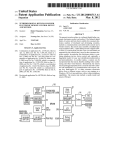
or PDA) or a smart phone, but has a loW cost and feature set
(21) Appl. No.:
12/210,782
supported by the console that is novel in the consumer elec
tronics market. In particular, this disclosure relates to com
(22) Filed;
sep_ 15, 2008
bining telephone service, device control and, optionally, a
?ngerprint reader for easy user identi?cation/authoriZation
.
.
and
Related U's' Apphcatlon Data
ersonaliZation. As another 0 tion, a camera can be
incorlporated into the remote, therebry enabling video confer
(63) Continuation of application No. 11/465,749, ?led on
encing and other Visual features- Alternatively, the remote
Aug 18, 2006, HOW pat NO_ 7,444,130, which is a
cominuation_in_pan of application NO_ 113503980,
may be packaged separately from a console and sold to inter
act With capabilities of a communications and console, set
?led on Feb 8 2006 HOW Pat NO 7 389 103'
top box, multi-media PC or other consumer electronics
’
(60)
’
’
’
device from a different source, such as one running on a
Windows, OS X or Linux platform, With or Without telephone
capabilities. The remote may include a media reader and
remote USB port.
Provisional application No. 60/709,666, ?led onAug.
19, 2005.
/lOO
/ Ill
m
FINGER
CHIP
SPl/HIGH SPEED
SENSOR
PARALLEL PORT
8Mb Flash
/
UARTO
17.7.
naEE
auEE
mam:
:22:
.
W
/
GPIO
'
y
E u I, &
P89LPCB31
KEYBOARD
/l32
ZEEVO ZV43D1
y
y 12c
KEYPAD
Codec
,.
BLU ETOOTH SOC
CONTROLLER
LPC 21 32
/ 12:5
GPIO
EXT INT
TRACK BALL
GPIO
I53
LCD MODULE
POWER
FROM
“7-
CRADLE
SUPPL
_ 5,,
3.6V NI-NM
BATTERY
H3
»
/
|zlj
3.3V REG
BUCK/BOOST
Debug
r
Reset Input
DEBUG
header
Patent Application Publication
Jan. 8, 2009 Sheet 1 0f 6
NE!
in
US 2009/0009356 A1
mm.
0:2
in: Al
0230
‘IUkOPmDQJ
£5ENE
DM430OI5
O“4r.1:?mw
QPMED
ONmnr:w
152 % AFmi1-492"a
ON_:
M GZE EIU mowz
msnmo Sumac
O,7DimwD
Patent Application Publication
Jan. 8, 2009 Sheet 2 0f 6
' """"""""""""""
US 2009/0009356 A1
w/zw
FIG. 2
2:5‘
Patent Application Publication
Jan. 8, 2009 Sheet 3 0f 6
4-13? GB
US 2009/0009356 A1
mFFFF FFFF
AHH Peripherals
3.7: as
emlltgr? DUDE!
'IJF‘B Peripharaia
3 5, GB
Eka'EDBD ‘53%
w GB _
r 111cm} nnuu
Reserved Address
Sigma
2 E GB
ire-mu fmmmam
Dix-3524p men m-sacgil
GxEDUU
Reserved Address Epace
,
32 is cm-cr
.
i
i
-w
amp RAM LPczmai
331L222
x "
RT
16 k5 {In-Chip 32mm:
“ “ SAM {LP921132}
‘
’
$2322
5‘ '
a as {mitt-rip 515%: ‘RAM gLPc-zifm
gxinnn
m‘ ‘DUB *FFF
mi GB
0x405!) mum;
HEEENK? ?rddreaséimee
E1358? $222
1.! 211
a:
I’
5321B 0:: 121.41 Mn Jalaufe Fulanonnfi?EB)
‘gxuum
?lial
»:4 hi Din-Chip NT- ?maarine Memory gammy ‘MODE FFFF
.
a‘
._r,,_g|1_'_1>
-
gxununfg?ga
22 k5 ran-chip l-lczn-ifulaizile Mama-r11 rimmr; ‘JUDGE’ ‘FF F
GB
Main Proc
LPC 2132
?ew
I
@xDUDH Haw
Keyboard Ctlr
-<-—>
P89LP931
£95
k
FIG. 4
Keyboard Matrix
<—> (8 return lines x 13 scan ?nes)
‘i106
Patent Application Publication
Jan. 8, 2009 Sheet 4 0f 6
LPG 2132 CPU
US 2009/0009356 A1
M49 BVBQZA
UART
EB!
314301 Bluetaath SOC
502.,
-. --., -
MSM-??16 OK‘
modem
.
Mia
IS\
Speaker
‘WI
152.
FIG. 5
Patent Application Publication
Jan. 8, 2009 Sheet 5 0f 6
mU‘IhE
dim-Au
US 2009/0009356 A1
Jan. 8, 2009
US 2009/0009356 A1
TETHERED DIGITAL BUTLER CONSUMER
ELECTRONIC DEVICE AND METHOD
feature set and a cost-effective allocation of technical tasks
betWeen a remote and a console.
RELATED APPLICATIONS
SUMMARY OF THE INVENTION
[0001] This application is a continuation of US. applica
tion Ser. No. 11/465,749 ?led Aug. 18, 2006 Which is a
continuation-in-part of and claims priority to US. application
Ser. No. 11/350,980 ?led Feb. 8, 2006 by inventor Robert
Stepanian, entitled, “TETHERED DIGITAL BUTLER
CONSUMER ELECTRONIC DEVICE AND METHOD”,
Which claims the bene?t of US. Provisional Application No.
60/709,666 ?ledAug. 19, 2005; it further claims the bene?t of
and priority to US. Provisional Application No. 60/709,666
[0006] The present invention relates to a tethered digital
butler consumer electronics product and method. The teth
?led Aug. 19, 2005.
[0002] This application is related to US Design Pat. Appli
cation Nos. 29/236,023, 29/236,022 and 29/236,022, ?led on
Aug. 10, 2005 by inventors Phoebe Ng, Robert Stepanian and
Allison S. Conner, entitled, “NAVIGATION BUTTON
ARRAY FOR REMOTE CONTROL HOUSING”,
“REMOTE CONTROL HOUSING” and “CONSOLE
HOUSING”. The priority, provisional and related design
applications are incorporated by reference.
ered digital butler, of a price and form factor suitable for
consumer electronics markets of developed and developing
countries, includes a communications and multi-media con
sole and a Wireless remote. The remote may resemble a hand
held personal computer (HPC), a palm-held personal com
puter (PPC or PDA) or a smart phone, but has a loW cost and
feature set supported by the console that is novel in the con
sumer electronics market. In particular, this disclosure relates
to combining telephone service, device control and, option
ally, a ?ngerprint reader for easy user identi?cation/authori
Zation and personalization. As another option, a camera can
be incorporated into the remote, thereby enabling video con
ferencing and other visual features. Alternatively, the remote
may be packaged separately from a console and sold to inter
act With capabilities of a communications and console, set
top box, multi-media PC or other consumer electronics
device from a different source, such as one running on a
BACKGROUND OF THE INVENTION
[0003] The present invention relates to a tethered digital
butler consumer electronics product and method. The teth
WindoWs, OS X or Linux platform, With or Without telephone
capabilities. The remote may include a media reader and
remote USB port. Particular aspects of the present invention
are described in the claims, speci?cation and draWings.
ered digital butler, of a price and form factor suitable for
consumer electronics markets of developed and developing
countries, includes a communications and multi-media con
sole and a Wireless remote. The remote may resemble a hand
held personal computer (HPC), a palm-held personal com
puter (PPC or PDA) or a smart phone, but has a loW cost and
feature set supported by the console that is novel in the con
sumer electronics market. In particular, this disclosure relates
to combining telephone service, device control and, option
ally, a ?ngerprint reader for easy user identi?cation/authori
Zation and personalization. The remote may be packaged
separately from a console and sold to interact With capabili
ties of a communications and multi-media console from a
different source, such as one running on a WindoWs, OS X or
Linux platform.
[0004] Convergence of digital devices is not unbounded,
BRIEF DESCRIPTION OF THE DRAWINGS
[0007]
FIG. 1 is a block diagram of the digital butler
remote.
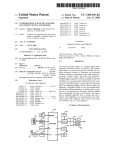
[0008] Details of the main processor are depicted in FIG. 2.
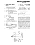
[0009] The LPC 2132 memory maps are shoWn in FIG. 3.
[0010] FIG. 4 shoWs the 8051 based Philips LPC89LPC931
controller.
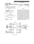
[0011] FIG. 5 shoWs the ZV4301 to other CPU and periph
eral interfaces.
[0012] FIG. 6 is a block diagram ofthe console.
[0013] FIG. 7 is an alternative block diagram of the digital
butler remote, With a CMOS camera module and/ or memory
card reader.
DETAILED DESCRIPTION
because it is guided by market realities. Many concepts are
?oated as trial balloons that burst, never to see an enabling
development effort or a reduction to practice. Some conver
gence trends are strong and noteWorthy. Cellular smartphones
or business phones such as Treo or Blackberry products are
[0014]
The folloWing detailed description is made With ref
erence to the ?gures. Preferred embodiments are described to
illustrate the present invention, not to limit its scope, Which is
de?ned by the claims. Those of ordinary skill in the art Will
becoming poWerful and supplanting separate PDAs. These
recogniZe a variety of equivalent variations on the description
smartphones go With the user across a cellular netWork and
that folloWs.
even overseas. They are untethered, packing many features
into a small form factor, not requiring a console. Another
trend is to repackage a PC as media center, complete With a
held remote With a novel combination of features that are
Wireless keyboard. Recent announcements suggest interfac
ing a Microsoft media center With a Bluetooth-equipped cel
lular telephone to use the sound reproduction of a TV as a sort
of speaker phone, relying on the cellular telephone for net
Work connectivity. In both instances, the telephone features
are untethered from and do not depend on availability of a
console.
[0005]
For developing countries and cost-conscious buy
[0015]
A tethered digital butler produces a loW cost, palm
implemented by logic and resources of the console, con
nected Wirelessly to the palm-held remote. Tethering the
palm-held device, so that it depends on logic and resources of
the console, runs against the trends and teachings of the
consumer electronics industry and particularly against the
trend toWard more poWerful smartphones.
[0016] Various novel combinations of features are empha
siZed in this application. One Will recogniZe that the features
discussed can be combined in many Ways, While remaining
too expensive. An opportunity arises to provide a loW-cost
faithful to the tethered digital butler concept.
[0017] In a ?rst embodiment of the tethered digital butler,
integrated consumer electronics system that includes a novel
the palm-held remote alloWs a user to select among and use
ers, the Treo and media center approaches are over-built and
US 2009/0009356 A1
logic and resources of a bread-box or smaller sized console to
authenticate users from a ?ngerprint reader on the remote, to
Jan. 8, 2009
personalize the user’s telephone, TV vieWing, media access
remote may function in tandem With a console, PC or set top
cable or satellite box. It also could be con?gured to control
other consumer electronics device such as a TV, IP-TV, home
and internet browsing experiences, to connect the user to a
theater system, component stereo, digital video recorder,
telephone netWork consistent With the user’s authentication,
DVD player or recorder, VCR, etc. It can receive streaming
media directly from a server. The palm-held remote may be
and to control multi-media features, such as channel control,
volume control, DVD/CD playback control, and digitally
combined With a glue logic application that enables a console,
stored music access and playback. In this embodiment, the
palm-held remote integrates at least a ?ngerprint reader, a
speaker, microphone and volume control adapted for use as a
PC, set top box or other consumer electronics device to utiliZe
telephone, a display at least capable of shoWing a telephone
number, a cursor control and trigger adapted to select and
control resources of the console, a compact keypad including
numeric keys usable for telephone dialing, the compact key
pad further including alphabetic keys usable for Web broWs
ing. The bread-box or smaller siZed console integrates at least
a DVD/CD player, a netWork port and logic and resources
adapted to authenticate users of the palm-held remote and
the special purpose controls of the remote. The remote may be
adapted to invoke a glue logic application supplied for or
native to a communications and/ or multi-media console, such
as one running under WindoWs, OS X or Linux.
[0022] In a sixth embodiment, a remote control for a gate
Way device t is coupled to multimedia and communication
resources. The gateWay device including logic and resources
to process Wireless input and provide access to the multime
dia and communication resources. The remote control
personaliZe their telephone netWork connection and their
includes a palm-held remote adapted to invoke glue logic
running on the gateWay device by Wirelessly directing input to
Internet broWsing based on ?ngerprints received from the
the gateWay device. It integrates at least a speaker and volume
palm-held remote, connect telephone features of the palm
control adapted for use as a remote speaker, a ?ngerprint
reader and a cursor control and trigger adapted to select and
control resources of the console. Glue logic invoked Wire
held remote to the telephone netWork, respond to Internet
broWsing commands from the palm-held remote and display
Web pages on a monitor or television, control channels
lessly by the remote control is adapted to connect the speaker
accessed by a video receiver, drive speakers and provide
volume control, provide playback control for the DVD/CD
player, and access and playback digitally stored music.
to a sound reproduction module and connect the ?ngerprint
reader to an authentication and personalization module that
selects a user pro?le based on activation of the ?ngerprint
reader and authentication of the user. The personaliZation
[0018]
In a second embodiment of the tethered digital but
ler, the palm-held remote has feWer components; the console
supports feWer features; thus, the combination Will be less
expensive and more attractive in many markets. Remote com
ponents then include a speaker, microphone and volume con
trol adapted for use as a telephone, a display at least capable
of shoWing a telephone number, a cursor control and trigger
adapted to select and control resources of the console, and a
compact keypad including numeric keys usable for telephone
module adapted to present the user’s personaliZed favorite
media access, present the user’s personaliZed history lists,
automatically authenticate the user for digital rights manage
ment, automatically authenticate the user for communication
access, and automatically authenticate the user for electronic
Wallet reproduction of purchasing credentials.
[0023] An alternative to video operation of a camera is still
operation of the camera. The still camera may be Wirelessly
coupled to a photographic capture module running on another
dialing. The ?ngerprint reader is not included, nor is the
alphabetic keypad. The logic and resources of the console are
reduced accordingly. Logic and resources of the console need
the other device can simplify the remote and reduce its co st, as
not authenticate and personaliZe based on ?ngerprints or
only temporary buffering in the remote is needed.
access and playback digitally stored music. Internet broWsing
may be limited or may be supported by an on-screen key
board.
[0019] In a third embodiment of the tethered digital butler,
the DVD/CD player is omitted from the console. The features
of the palm-held remote do not much change, but the logic
device, Which persists the pictures taken. The persistence at
[0024] An aspect of this disclosure that can be combined
With any of the foregoing embodiments is remote on-screen
menu and controls display, translating a device menu and
controls display that Would normally appear on a TV or
monitor for reproduction on a display that is part of the
remote. To implement this capability, a menu-generating
and resources required of the console are reduced.
device can assemble on-screen menus and controls as sepa
[0020]
rate data stream, apart from any video image that the menus
and controls overlay. The data stream can be supplied both to
In fourth embodiment, the console is implemented
on a PC, Which may be larger than bread-box siZed. This
typically Would be less desirable, as most PCs do not ?t a
media room decor and are relatively loud, due to fans and hard
disk rotation. A neW generation of PCs, such as the Mac Mini,
presents a small form factor (presently 6.5><6.5><2 inches) and
quiet operation, While including enough computing poWer to
the device’s oWn on-screen overlay generator and to a com
munications module coupled to the remote. The remote uses
the data stream to render the on-screen display in a legible
format, adapted to the reduced siZe of a screen on the remote.
Preferably, the menu and control organiZation format on the
function as PC.
remote mimics What the vieWer can see on the screen, to
[0021] In a ?fth embodiment, the remote is emphasiZed.
One aspect of the remote is to provide a complete I/O plat
form in the palm of the user’s hand. Features adaptable to
VoIP and/or video phone operation, such as a microphone,
minimiZe confusion. Technologies such as a subset of HTML
and JavaScript alloW a designer to specify a menu and control
layout in terms that permit rendering to a variety of display
can be used for other purposes, such as dictation, note taking,
siZes. Remote display of the on-screen menu and control data
stream may preempt a video image display or may be overlaid
voice messaging, listening to music or remote vieWing video.
To support the high demands of streaming video, a broader
on top of the video image. Optionally, the device’s on-screen
menu and controls can be supplied to the remote exclusively
communications channel, such as Bluetooth version 2 or later
or 802.1 In, and a more poWerful processor are included. The
avoid confusing menus of different siZes. Alternatively, the
as a data stream and not as part of a rendered video stream, to
Jan. 8, 2009
US 2009/0009356 A1
on-screen menus and controls may just appear on the
remote’s display as a consequence of being rendered to a TV
or monitor that is reproduced on the remote’s display.
[0025]
In any of these embodiments, a camera module can
be incorporated into the remote, thereby enabling video con
ferencing and other visual features. The camera is comple
mented by a glue logic application supplied for or native to a
communications and/ or multi-media console, such as one
doWs XP implementations. This degree of context shifting
based on a single action at a remote control is believed to be
neW and unique. The personaliZation may include: favorite
channels/movies/shoWs in a streaming video environment;
favorite music, photos or video in an on demand environment;
approved access to DRM-controlled content using one or
more keys linked to the ?ngerprint; history of searches, recent
topics, personal interest (a la Google Sidebar or Claria Per
running under WindoWs, OS X or Linux. To support full
sonalWeb), personal receptiveness to advertising content,
motion video, Bluetooth version 2 or later or a Wireless Eth
ernet protocol may be used to supply the required bandWidth.
recently accessed ?les; automatic authenticated access to
communication channels linked to the ?ngerprint, such as
[0026] As a further aspect of these embodiments, the con
sole may be equipped With a non-volatile memory siZed to
voice over IP, instant messaging, Web conferencing and
e-mail; electronic Wallet access, automatically looking up
time-shift playback from the video receiver and its logic and
credit card information and other account authoriZation infor
resources are further adapted to provide a menu of upcoming
mation; and sharing of information by person logged in.
video content, schedule recording of the video content and
replay the video content. Alternatively, the non-volatile
control button that causes the remote to emit a tone Which
memory may be siZed to hold a library of digital music.
[0027]
The U0 platform in the palm of our hand concept
can be enhanced by adding a memory card reader to the
remote. One or more of the many memory card formats noW
in use or as may be developed in the future can be accommo
dated.
[0028] Another form of U0 is provided through a USB or
FireWire port. The remote may integrate a USB connector and
port or similar FireWire support. Glue logic running on the
host device may be adapted to treat the USB or FireWire port
as if it Were local to a machine being accessed using the
remote.
[0029] In another aspect of these embodiments, the remote
may hold a DRM key and automatically deliver the key to
DRM-enabled device. Either memory on the remote, a
memory module or an identi?cation reader combined With
the remote may hold the DRM key. The identi?cation reader
can read a smart card or similar module With memory or can
read a ?ngerprint in order to authoriZe automatic use of the
DRM key to exercise DRM-evidenced rights. When a user
[0031]
The console may be equipped With a remote locator
makes it easier to locate.
[0032] The form factor of a palm-held remote should be
easily recognized.
[0033] The form factor of a bread-box or smaller siZed
console can be judged by volume. A smallish consumer elec
tronics component uses an enclosure (from Which connectors
and feet protrude) that is 12 by 15 by 3 inches and has a
volume of 540 cubic inches. This is an approximately bread
box siZed enclosure, although the shape differs from a loaf of
bread.
Remote Hardware
[0034]
Introduction
[0035] The digital butler remote is a gadget based on the
Bluetooth or another Wireless technology used for communi
cations and remote control applications.
[0036]
Features
[0037]
The digital butler remote board is an ARM7 proces
visits a neighbor’s console, they may take along their hand
sor based solution.
held remote and the associated digital rights for use on the
neighbor’s console or other device.
[0030] Another feature that can be combined With any of
these embodiments is personaliZation based on a single
[0038] This remote is built around the Philips LPC2l32
ARM controller. The main processor provides interfaces for
the Keypad, Trackball or other pointing device, 128*32
graphics LCD module, ?ngerprint sensor, and Bluetooth
action, a sWipe of the ?ngerprint reader. Coupled Wirelessly
SOC. The Bluetooth SOC and Zeevo ZV4301 interface With
to the ?ngerprint sensor softWare is a personaliZation module.
a microphone, speaker and headphone for voice utilities. The
If a user does not identify himself by sWiping the ?ngerprint
sensor, then a generic pro?le is applied to personaliZation of
system may use a Philips 89LPC931 controller for the keypad
interface through a I2C Bus. Alternative hardWare con?gura
music, movies, photos, videos, ?les and telephone access. If
the user sWipes the ?ngerprint sensor, then personaliZation
tions are illustrated in FIGS. 7 and 8.
can be applied, analogous to sWitching users in current Win
remote.
[0039]
FIG. 1 is a block diagram of the digital butler
Embodiment Details
Chip Name
Chip number
Description
Main processor
LPC2132, Philips.
Main CPU, 60 MHZ/64 Kb ?ash/l6 Kb
(100)
Keypad controller
(122)
LCD Display module
(133)
TrackBall (123)
89LPC931, Philips.
DDGl28032AAD, DDTL.
TBWBZAOO, ITT
Industries, Cannon;
Omni- or Vari-Point or
Omni- or Vari-Disk
SRAM
8051 MCU compatible With 8 KB ?ash,
12C interface.
128*32 graphics parallel/serial LCD
Module.
Miniature all directional scanning sWitch.
Jan. 8, 2009
US 2009/0009356 A1
-continued
Embodiment Details
Chip Name
Chip number
Description
devices, ITT Industries,
Cannon.
Fingertip sensor (121)
AES3400, Authentech.
Bluetooth SOC (132))
ZV4301, Zeevo or
Fingertip sensor with SPI interfaces.
Bluetooth SOC With, UART interface.
equivalent by Broadcom or
RSMD.
Flash Memory (131)
AT49BV802A, Atmel.
MSM7716, OKI.
Bluetooth SOC Flash, 8 Mb
Codec IC (141)
Power Supply (113)
LTC 3440EDD - Linear
Micro power synchronous 600 ma Buck
Technology.
Boost Dc-DC converter
Single rail codec.
[0040] Additional details of the main processor are
depicted in FIG. 2. The LPC2132 (100) is based on a 32/16
bit ARM7TDM1-S CPU (232) with real time emulation and
two Fast I2C-bus (400 Kb/s) (244), SPI and SSP (245)
with buffering and variable data length capabilities.
[0047] Vectored interrupt controller (253) with con?g
embedded trace support, together with 64 Kbytes (KB) of
embedded high speed ?ash memory (223). A 128 bit wide
memory interface (211, 212, 222) and accelerator architec
urable priorities and vector addresses.
[0048] Up to 47 5 V tolerant general purpose I/O pins
ture enable 32 bit code execution at maximum clock rate. For
critical code size applications, an alternate 16 bit “thumb
[0049]
mode” reduces code by more then 30% with minimal perfor
mance penalty. Due to their tiny size and low power consump
tion, these micro controllers are typically used for miniatur
iZed applications, such as hand-held equipment. Most
[0050]
peripheral pins can also be remapped as General Purpose I/O
pins. The system includes on-chip SRAM of 1 6 KB (213) and
[0052]
is well suited for communication gateways and protocol con
verters, soft modems, voice recognition and low end manag
[0053]
ing, providing both large buffer siZe and high processing
power. Various 32-bit timers (247, 248), 10-bit 8 channel
ADC(s) (226), 10-bit DAC (227), PWM channels (225) and
47 GPIO lines (228) with up to nine edge or level sensitive
external interrupt pins, make these microcontrollers particu
larly suitable for industrial control and hand-held systems.
[0041] The integrated ARM microprocessor operates at 60
MHZ and, in one embodiment, supports the following fea
tures:
[0042] 16/32-bit ARM7TDM1-S microcontroller (232)
in a tiny LQFP64 package.8/16/32 KB of on-chip static
RAM (213) and 64/512 KB of on-chip Flash program
memory (223). A 128 bit wide interface/accelerator
(211, 212, 222) enables high speed 60 MHZ operation.
[0043] In-System/In-Application Programming (ISP/
IAP) via on-chip boot-loader software. Single Flash sec
tor or full chip erase in 400 ms and programming of 256
bytes in 1 Ms. Embedded Trace interfaces (231) offer
real-time debugging with the on-chip real monitor soft
ware and high speed tracing of instruction execution.
One 8 channel 10-bit A/D converters (226) provides a
total of up to 16 analog inputs, with conversion times as
low as 244 us per channel.
[0044] Single 10-bit D/A converter (227) provides vari
able analog output.
[0045] Two 32-bit timers/counters (with four capture
and four compare channels each)(225), PWM unit (six
outputs) (225) and watchdog (248).
[0046] Real-time clock (247) equipped with indepen
dent power and clock supply permitting extremely low
power consumption in power-save modes. Multiple
serial interfaces including two UART (16C550) (246),
(228) in tiny LQFP64 package.
Up to nine edge or level sensitive external inter
rupt pins (224) available.
60 MHZ maximum CPU clock available from
programmable on-chip PLL (241).
[0051]
On-chip crystal oscillator with an operating range
ofl MHZ to 30 MHZ.
Power saving modes include idle and Power
down.
Individual enable/disable of peripheral functions
as well as peripheral clock scaling down for additional
power optimiZation.
[0054]
Processor wake-up from Power-down mode via
external interrupt (224).
[0055]
Single power supply chip with POR and BOD
circuits.
[0056] CPU operating voltage range of 3 .0 V to 36 V (33
V:10%) with 5 V tolerant I/ O pads.
[0057] The LPC 2132’s 64 KB of ?ash memory (223) may
be used for both code and data storage. Programming of the
?ash memory may be accomplished in several ways. It may
be programmed in the system via the serial port (245). The
application program may also erase and/ or program the ?ash
while the application is running, allowing ?exibility for data
storage ?eld ?rm grade upgrades, etc. While the on chip boot
loader is used, 64 KB ?ash memory is available for user code.
The LPC2132 ?ash memory provides a minimum of 100,000
erase/write cycles and 20 years of data retention. On-chip
static RAM (213) may be used for code and/or data storage.
The SRAM may be accessed as 8 bits, 16 bits or 32 bits wide.
General purpose parallel I/ O is supported by device pins that
are connected to a speci?c peripheral function are controlled
by the GPIO registers. Pins may be dynamically con?gured as
inputs or outputs. Separate registers allow setting or clearing
any number of outputs simultaneously. The value of the out
put register may be read back, as well as the current state of
the port pins. The GPIO lines have the following features.
[0058] Direction control of individual bits.
[0059] Separate control of output set and clear.
[0060] All I/ O default to inputs after reset.
[0061]
The LPC 2132 memory maps shown in FIG. 3 incor
porate several distinct regions. In addition, the CPU interrupt
Jan. 8, 2009
US 2009/0009356 A1
vectors may be re-mapped to allow them to reside in either
[0077]
Flash memory (by default) or on-chip static RAM.
[0078] Arbitration betWeen simultaneously transmitting
[0062] The vectored interrupt controller (VIC) accepts all
of the interrupt request inputs and categorizes them as FIQ,
[0079]
vectored IRQ, and non vectored IRQ as de?ned by program
mable setting. The programmable assignment scheme means
that priorities of interrupts from the various peripherals can be
dynamically assigned and adjusted. Fast interrupt request
(FIQ) has the highest priority. If more than one request is
assigned to FIQ, the VIC combines the requests to produce
the FIQ signal to theARM processor. The fastest possible FIQ
latency is achieved When only one request is classi?ed as FIQ,
because then the FIQ service routine can simply start dealing
With that device. But if more than one request is assigned to
the FIQ class, the FIQ services routine can read a Word from
the VIC that identi?es an FIQ source that is requesting an
interrupt. Vectored IRAs have middle priority. Sixteen of the
interrupts can be assigned to this category. Any of the inter
rupt requests can be assigned to any of the 16 vectored IRQ
slots, among Which slot 0 has the highest priority and slot 15
has the loWest. Non-vectored IRQ’s have the loWest priority.
[0063] The VIC combines the requests from all the vec
tored and non-vectored IRAs to produce the IRQ signal to the
ARM processor. The IRQ service routine can start by reading
the register from the VIC and jumping there. If any of the
vectored IRAs are requested, the VIC provides the address of
the highest-priority requesting IRAs service routine, other
Wise it provides the address of a default routine that is shared
by all the non vectored IRAs. The default routine can read
another VIC register to see What IRAs are active.
[0064] The LPC 2132 contains tWo UARTs (246). One
UART provides a full modem control handshake interface,
the other provides only transmit and receive data lines. The
features of UART is listed beloW:
[0065] 16 byte, receive and transmit FIFO s.
[0066] Register locations conform to ‘550’ industry stan
dard.
[0067]
Receiver, FIFO trigger points at l, 4, 8, and 14
bytes.
[0068]
[0069]
Built in baud rate generator.
Standard modem interface signals included on
UART 1.
[0070] I2C (244) is a bi-directional bus for inter IC control
using only tWo Wires, a serial clock line (SCL) and a serial
data line (SDA). Each device is recognized by a unique
address and can operate as either a receiver only device or a
transmitter With the capability both to receive and send infor
mation.
[0071] Transmitters and/or receivers can operate in either
master or slave mode, depending on Whether the chip has to
initiate a data transfer or is only addressed. I2C is a multi
master bus that can be controlled by more than one bus master
connected to it.
[0072] I2C implemented in LPC2l32 support bit rate up to
400 kbit/s (Fast I2C). The features of LPC2l32 I2C bus is
listed beloW:
[0073] Standard I2C compliant bus interface.
[0074] Easy to con?gure as master, slave, or line-select
master or slave.
[0075] Programming clocks alloW versatile rate control.
[007 6] Bi-directional data transfer betWeen masters and
slaves.
Multi master bus(no center master)
masters Without corruption of serial data on the bus.
Serial clock synchronization alloWs devices With
different bit rates to communicate via one serial bus.
[0080] Serial clock synchronization can be used as a
hand shack mechanism to suspend and resume serial
transfer.
[0081] The I2C bus may be used for test diagnostics
purposes.
[0082] The SPI (245) is a full duplex serial I/O interface,
designed to be able to handle multiple masters and slaves
connected to a given bus. A single master and a single slave
communicate on the interface during a given data transfer.
During a data transfer, the master alWays sends a byte of data
to the slave, and the slave alWays sends a byte of data to the
master. The features of the SPI controller is listed beloW:
[0083] Compliant With serial peripheral interface (SPI)
speci?cation.
[0084] Synchronous, serial, full duplex, communication.
[0085]
[0086]
Combined SPI master and slave.
Maximum data bit rate of one eighth of the input
clock rate.
[0087]
The real time clock (RTC) (247) is designed to pro
vide a set of counters to measure time When normal or ideal
operating mode is selected. The RTC uses little poWer, mak
ing it suitable for battery poWered systems Where the CPU is
not running continuously (idle mode). The features of RTC
are described beloW.
[0088] Measures the passage of time to maintain a cal
endar and clock.
[0089] Ultra loW poWer design to support battery poW
ered systems.
[0090] Provides seconds, minutes, hours, day, month,
year, day of Week, and the day of year.
[0091] Programmable reference clock divider alloWs
adjustment of the RTC to match various crystal frequen
cies.
[0092] The 8051 based Philips LPC89LPC931 controller
in FIG. 4 is suitable for keyboard interface. The P89LPC930/
931 (404) is based on a high performance processor architec
ture that executes instructions in tWo to four clocks, six times
the rate of standard 80C5l devices. Many system-level func
tions have been incorporated into the P89LPC930/ 931 in
order to reduce component count, board space, and system
cost. The P89LPC931 has the folloWing enhanced features:
[0093] A high performance ARM processor 80C5l CPU
provides instruction cycle times of 1 11 ns to 222 ns for
instructions except multiply and divide, When executing
at 18 MHz. This is six times the performance of the
standard 80C5l running at the same clock frequency. A
loWer clock frequency for the same performance results
in poWer savings and reduced EMI.
[0094] 2.4 V to 3.6 VVDD operating range. I/O pins are
5 V tolerant.
[0095] 8 kB ?ash code memory With 1 kB sectors, and
64-byte page size.
[0096] Byte-erase alloWing code memory to be used for
data storage.
[0097] Flash program operation completes in 2 ms.
[0098] 256-byte RAM data memory.
[0099]
timer.
Real-time clock that can also be used as a system
Jan. 8, 2009
US 2009/0009356 A1
[0100]
Enhanced UART With fractional baud rate gen
erator, break detect, framing error detection, automatic
address detection and versatile interrupt capabilities.
[0101] 400 kHZ byte-Wide I2C-bus communication port.
[0102] Eight keypad interrupt inputs, plus tWo additional
external interrupt inputs.
[0103] Four interrupt priority levels.
[0104]
On-chip poWer-on reset alloWs operation Without
external reset components. A reset counter and reset glitch
suppression circuitry prevent spurious and incomplete resets.
-continued
Keyboard Controller to Matrix Interface
P89LPC93
Signal
Signal
Name
K130.0 Keybd output 1
P20
key board
SCAN LINE 1
Keybd Scan
line 1
K130.1 Keybd output 2
P21
SCAN LINE 2
Keybd Scan
line 2
A software reset function is also available.
[0105] The keypad 8*13 matrix (406) is connected to the
GPIO lines of P89LPC931 micro controller (404). The key
K130.2 Keybd output 3
P22
SCAN LINE 3
connected to the keyboard port of the P89LPC931 micro
controller. The P89LPC931 is connected to the main proces
sor LPC2132 through the I2C bus to minimiZe the number of
pins on the main processor.
[0106] The custom softWare is loaded into the ?ash pro
gram memory of the P89LPC931 micro controller Which
scans the keypad and generates ASCII codes and communi
cates to the main processor through the I2C bus. The
P89LPC931 micro controller is normally kept in poWer save
mode, and it Will aWaken in response to keyboard interrupts
after the key press. The keyboard port of P89LPC931 has a
change on status interrupt feature, and hence any key press
Will generate the keyboard interrupt. The key bounces are
taken care of by the softWare.
Keybd Scan
line 3
K130.3 Keybd output 4
P23
SCAN LINE 4
pad has 8 return lines and 13 scan lines. The return lines are
[0107]
Remarks
Keybd Scan
line 4
KBOA Keybd output 5
P24
SCAN LINE 5
K130.5 Keybd output 6
P2.5
SCAN LINE 6
K130.6 Keybd output 7
P26
SCAN LINE 7
K130.7 Keybd output 8
P27
SCAN LINE 8
K130.8 Keybd output 9
P1.0
SCAN LINE 9
K130.9 Keybd output 10
P1.1
SCAN LINE 10
Keybd Scan
line 5
Keybd Scan
line 6
Keybd Scan
line 7
Keybd Scan
line 8
Keybd Scan
line 9
Keybd Scan
line 10
K130.10 Keybd output 11
P1.4
SCAN LINE 11
Keybd Scan
line 11
K130.11 Keybd output 12
P1.6
SCAN LINE 12
Keybd Scan
line 12
K130.12 Keybd output 13
P1.7
SCAN LINE 13
Keybd Scan
line 13
The QWERTY keyboard may have a Chinese char
acter entry feature and the software transfers the Chinese
corresponding ASCII codes to the main processor in Chinese
[0109]
key entry mode.
embodiment, is a 128*32 dot matrix LCD module. The LCD
[0108]
The folloWing tables describe interfaces among the
CPU (100), keyboard controller (404) and matrix (406):
The LCD display (133) DD12803AAD, in one
Module can be easily accessed via parallel micro controller
GPIO interface. Its features include:
[0110] Trans?ective display mode and positive type,
B/W mode, FSTN LCD.
[0111] Graphic 128*32 dot-matrix display format.
Keyboard Controller to CPU Interface
Signal
LPC2132
Serial I2C Data
Serial I2C clock
SDA
SCL
P89LPC93
SDA
SCL
[0112]
Remarks
I2C interface
I2C interface
Keyboard Controller to Matrix Interface
P89LPC93
Signal
Signal
K131.0 Keybd input 1
Name
P0.0
Parallel input data from micro controller.
[0113]
1/33 duty multiplexing ratio.
[0114]
[0115]
[0116]
[0117]
1/6 bias.
6 o’clock vieWing direction.
Dimension outline 35(W)*28.9(H)*1 .75(D) mm.
Resolution 128*32 dots.
[0118]
Active area 29.66(W)*8.45(W) mm.
[0119]
Dots pitch 0.232(W)*0.265(H) mm.
[0120] Dots size 0.202(W)*0.235(H) mm.
[0121] The ITT Industries, Cannon TBWB2A00 trackball
(123) is a miniature all directional scanning sWitch developed
for mobile, remote, PDA, notebook PC, and hand-held device
key board
Remarks
RET LINE 1
Keybd
applications. It includes tWo perpendicular rollers actuated by
Return line 1
friction on the ball and tWo spring contacts Which generate
KBI.1 Keybd input 2
P0.1
RET LINE 2
Keybd
K13I.2 Keybd input 3
P02
RET LINE 3
Keybd
K13I.3 Keybd input 4
P0.3
RET LINE 4
Keybd
can be included With the trackball and driven according to the
Return line 4
KBIA Keybd input 5
PO.4
RET LINE 5
Keybd
Wishes of the user. Several tactile effects can be obtained
K13I.5 Keybd input 6
P0.5
RET LINE 6
Keybd
K13I.6 Keybd input 7
P06
RET LINE 7
Keybd
K13I.7 Keybd input 8
P0.7
RET LINE 8
Keybd
Return line 2
Return line 3
Return line 5
Return line 6
Return line 7
Return line 8
(by contact closing and opening) the electrical pulses and a
light tactile effect (click) at each pulse. A sWitch called
“Select” is integrated in the trackball. Optimally, tWo LEDs
according to the number of tooth integrated in the gear axle;
the standard resolution is 12 pulses perball rotation. When the
Trackball is activated, its relative position changes are ana
lyZed in tWo directions X andY. The tWo perpendicular rollers
are actuated by friction on the ball. During their revolution,
the rollers activate tWo spring contacts Which generate (by
contact closing and opening) the electrical pulses.
Jan. 8, 2009
US 2009/0009356 A1
[0122]
To track the ball movements, a simple electronic
device tied to the direction contacts converts the vertical and
horizontal displacements of the both perpendicular rollers in
logical levels of X-axis andY-axis displacements: Some pull
up resistors (or respectively pull doWn resistors) are tied to the
axis direction contacts While the common contact is tied to the
ground (or respectively to the poWer supply potential). The
change in state interrupts the main LPC2132 processor (100).
The output pulse frequency is directly proportional to the
moving speed and the direction. The pulse frequency is pro
cessed by the main processor LPC2132 and the correspond
ing PS2 data sent to the host system.
[0123] Alternatively, the ITT Industries, Cannon Omni- or
Vari-Point joystick or the Omni- or Vari-Disk navigation disk
[0142] The interface of these ?ngertip sensors is pin
selectable choices. The SPI interface ?nger chip sensor
is selected so that the ?nger tip sensor is connected to the
SP1 port (245) of the main processor.
[0143] The Zeevo ZV4301 in FIG. 5 used in one embodi
ment is a Bluetooth SOC adapted to provide a high bandWidth
CPU system to add Wireless connectivity to their product. The
ZV 4301 (502) incorporates the industry standard 32 bit
ARM7TDM1 CPU core With high bandWidth processing
capability su?icient to support a Wide range of embedded
applications. The ZV4301 operates from —25C to 85C and
comes in a lead free version. The ZV4301 is implemented in
a 0.18 micro meter CMOS process and includes the integra
tion of all RF components and digital circuitry. The only
can be used instead of a trackball.
external components needed are an antenna, crystal, refer
[0124] The AuthenTec EntrePad, AES3400, AuthenTec’s
3rd generation loW poWer, small form-factor ?ngerprint iden
ence resister, decoupling capacitors, and ?ash memory. The
ZV4301 is designed for loW poWer applications including
ti?cation sensor IC (121). This product combines silicon
based image capture With a proprietary sensor control and
supply. The ZV4301 is manufactured in an 8.6><8.6><1.65 mm
matching algorithms to deliver ability-to-acquire (ATA) ?n
gerprint images and authentication. AuthenTec’s EntrePad
AES3400 utiliZes TruePrint Technology, alloWing the sensor
to look past the easily obscured outer surface of the skin to the
living layer beloW Where the unique ridge and valley patterns
of the ?ngerprint originate. Trueprint is AuthenTec’s unique
patented imaging technology. During imaging, a small near
?eld signal is generated betWeen the IC and the ?nger’s living
tissue layer. 16,384 individual elements in the sensor matrix
form a planar antenna array that receives this signal, creating
a digital pattern that accurately reproduces the ?ngerprint’s
underlying structure. A poWerful utility Within TruePrint is
Dynamic Optimization. This tool analyZes each image, con
trolling up to 15 sensor parameters to optimiZe the ?ngerprint
image, regardless of unusual skin conditions or surface con
tamination. The TruePrint high-quality ?ngerprint imaging
technology enables reliable authentication.
[0125] The ?ngerprint sensor is small, battery friendly and
Well-suited to Bluetooth communications. These sensors
sleep and deep sleep modes, and operates from a single 3.3V
LTCC BGA package With 100 balls.
[0144] The ZV4301 is supplied With a link library for a
complete loWer layer protocol stack and source code to the
blueOS operating system, target manager and link manager
API. Upper layers are supported through the Zeevo partner
program With ?rmware, Bluetooth protocol stack softWare
and Bluetooth pro?les available from Zeevo’s extensive part
ner list.
[0145] The Zeevo4301 typical application supports AV
equipment, smart phones, personal digital assistants, printers,
cellular peripherals, access points and industry controls. Fea
tures include:
[0146] Bluetooth 1.2 compliant.
[0147] High bandWidth ARM7TDM1 processor sub
system.
[0148]
control and CPU are integrated.
automatically generate interrupts and reduce system over
head needed for ?nger detection.
[0126] Features of the ?ngerprint component, in one
embodiment, include:
[0151]
[0152]
[0127] TruePrint technology for ability to acquire (ATA)
[0128] Compact industry standard 100-Pin LQFP Pack
[0153]
age
[0129] High de?nition 128x128 TruePrint technology
based pixel array
[0130] 500 pixels per inch (ppi)
[0131]
Extended Range 2.7V to 3.6V single poWer sup
Ply
[0132]
0° C. to +700 C. operating temperature range
[0133] Easy to integrate USB 2.0 full speed, synchro
nous & asynchronous serial, & 8-bit parallel system
interfaces
[0134] 6 or 12 MHZ operation With crystal or supplied
clock input
[0135] USB selective suspend support
[0136] Ultra-hard surface coating
[0137]
[0138]
[0139]
[0140]
1 million rubs W/o degradation
Highly scratch resistant
IEC 61000-4-2 level 3 ESD capability (+/—8 KV)
Built-in loW poWer ?nger detection W/ system
interrupt capability
[0141]
LoW poWer operation; <6 mW/imaging event.
12, 24 and 48 MHZ CPU clocksiselectable on
chip PLL from single 12 MHZ input.
[0149] Highly integrated loW cost solution: Radio, link
[0150] High throughput.
Tested quali?ed softWare stack available.
Support for very loW poWer modesisleep and
deep sleep.
Audio capability on an SCO channel.
[0154] On chip crystal tuning and poWer calibration.
[0155] Complete co-location and co-existence solutions
With 802.11 supported through AWMA, AFH and SFH.
[0156]
The CPU and memory support include:
[0157]
ARM7TDMI processor core.
[0158]
[0159]
12 24 and 48 MHZ operation.
32/16 bit RISC architecture, 32 bit ARM instruc
tion.
[0160]
16 bit Thumb instruction set for increased code
density.
[0161] 32 bit ALU and high performance multiplier.
[0162] Extensive debug facilitiesiJ TAG.
[0163] 8 K bytes of boot ROM.
[0164] 64 K bytes of SRAM.
[0165] The radio features include:
[0166] Integrated RF interface connects directly to
antenna.
[0167]
lntegratedpoWer ampli?er supports up to +4 dBm
output poWer for class 2 & 3 operation.
Jan. 8, 2009
US 2009/0009356 A1
[0168] High sensitive design (—86 dBm typically).
[0169] Class 1 operation is supported With an external
poWer ampli?er/LNA interface.
[0170] IF4enhanced direct conversion receiver archi
tecture.
[0171] Integrated TX/Rx sWitch, balun, and matching
netWork in an LTCC package.
[0172] LoW poWer consumption receiver design.
[0173] Multiplexed RX/TX antenna interface.
[0174] Fully integrated PLL synthesizer and loop ?l
terirequires external 12 MHZ crystal.
[0175]
The baseband and software features include:
[0176] Required and optional Bluetooth 1.2 features
faster connection, extended SCO link, adaptive fre
quency hopping (AFH), QOS, ?oW control.
[0177] Direct memory access (DMA) for loW overhead
UART control.
[0178] Standard Bluetooth HCI interface over UART
and USB.
[0179] Support for a range of Bluetooth data rates (57.
6-723 Kb/ sec)
[0180] Support for multiple ACL and HC-SCO packet
types.
[0181] Park, sniff, and hold modes.
[0182] Point-to-point, point-to-multipoint, and scatter
net.
[0183] Up to 7 slaves and up to 4 Pico nets supported.
[0184] u-LaW, A-LaW and CVSD transcoders on SCO
channel
[0185] Full 8- to 128 bit encryption.
[0186] The baseband modem includes:
[0187] Demodulator, modulator, RX/TX self calibra
tion, burst timing control and transmitter burst spectral
shaping.
[0188]
FEC encoder/decoder, data Whitening, encryp
tion-decryption, and cyclic redundancy check.
[0189] Link controller for synchronization, frequency
hope control, and receiver/transmitter slot timing.
[0190]
[0191]
The external bus interface includes:
8,16-bit data bus.
[0192] 23-bit address bus.
[0193] Support for 2 memory banks. Each bank supports
up to 16 Mbytes ?ash and SRAM, With independent
timing control for each bank.
[0194]
GPIO can function as additional interrupts.
[0195] 3 dedicated chip selects, each With independent
timing control.
[0196] 3 indicated interrupt lines.
[0197]
16450 register set compatible UART.
[0199] 9600, 19.2K, 384K, 57.61K, 115.2K, 230.4K,
460.8K, and 921.6 Kbs UART baud rates.
RTS and CTS ?oW control signals for UART.
Direct Memory Access (DMA) for loW overhead
UART control.
[0202] The USB support includes:
[0203] USB version 2.0 compliant interface.
[0204] USB Wakeup and detach sideband signals sup
ported.
[0205]
Direct Memory Access(DMA) for loW overhead
USB control.
[0206]
[0212] The pulse code modulator support includes:
[0213] PCM interface for audio applications: PCM
OUT, PCM_IN, PCM_CLK, and
[0214] PCM SYNC.
[0215] Linear u-LaW and A-LaW codes supported.
[0216] Interface to OKI MSM/7732-01 and OKI 7716
codec.
[0217]
Direct Memory Access (DMA) for loW overhead
PCM control
[0218] A 12 MHZ crystal serves as the primary clock crys
tal.
[0219] FIG. 5 shoWs the ZV4301 to other CPU and periph
eral interfaces. The ZV4301 is interfaced With the main pro
cessor LPC2132 (100) through the UART port. The 8 Mb
Flash memory AT49BV802A (501) is interfaced With
ZV4301 through the external bus interface. The single rail
linear codec (141) is interfaced With the ZV4301 through the
PCM interface.
[0220]
Debugging of the remote is supported by JTAG
header and BDM header is used in the board for the debug
ging purposes. This section gives the details of the JTAG
header and BDM header.
[0221] The processor complies With the IEEE 1149.1A
JTAG testing standard. The JTAG test pins are multiplexed
With background debug pins.
[0222] The system is fed With 5 volts input poWer. The input
poWer is passed through a diode to provide the protection
against reverse polarity. The poWer to the digital butler remote
comes from an external poWer supply module. The external
poWer supply module Will provide poWer to the remote and
for charging the battery. The input poWer is fed through a
connector. From the 5 volts input, the folloWing voltages are
derived on the CPU card: Processor core voltage: The core
supply for the processor is generated through a loW dropout
regulator that can support current up to 15A operating from
a 5V-input. The output 1 .8V is fed to the core of the processor.
PLL voltage: The core voltage is the input to the PLL through
a ferrite bead, Which supplies poWer to clock generation and
PLL circuits of the processor.
[0223] Data sheets publicly available for the major IC com
ponents include:
1. LPC213x Philips User manual Nov. 22, 2004.
2. Zeevo ZV4301 Datasheet Jan. 24, 2005.
The UART includes:
[0198]
[0200]
[0201]
[0208] Con?gurable for UART Wake up hand shaking.
[0209] Base band and CPU activity indication.
[0210] USB/UART mode select.
[0211] Each GPIO can be used as interrupt.
The general purpose I/O features:
[0207] Sixteen individually programmable general pur
pose I/O.
3. P89LPC930/931 Data Sheet, Rev. 05-15 Dec. 2004.
[0224]
4. DDG128032AAD Data sheet, Rev1.0, Issue date:
2004/10/06
5. ITT Cannon, Miniature all direction scanning sWitch Data
sheet.
6. Authentec Fingerprint sensor AES 3400 Data sheet.
7. MSM7716 OKI Datasheet Version August 1998.
8.AT49BV802A Datasheet, Document 3405D-Flash-March/
2005 .
[0225]
In addition, a camera can be incorporated into the
remote, thereby enabling video conferencing and other visual
features. The camera is complemented by a glue logic appli
cation supplied for or native to a communications and/or
Jan. 8, 2009
US 2009/0009356 A1
multi-media console, such as one running under Windows,
OS X or Linux. A CMOS camera commercially available for
incorporation in camera phones may be suitable for this appli
cation. This is illustrated in FIG. 7.
[0226]
FIG. 7 depicts building the digital butler remote
board as an XScale processor based solution With a camera
module and/or memory card reader. This remote is built
around the Intel XScale micro controller or a digital signal
processor (DSP). The main processor provides interfaces for
the Keypad, Joystick, 320*240 graphics LCD module, ?n
gerprint sensor, Bluetooth SOC, WiFi 802.1lb/g module,
audio codec, camera module and memory card reader. The
audio codec interfaces With a microphone, speaker and head
phone for voice utilities. Alternatively, the microphone,
speaker and headphone could interface through the Bluetooth
support can be for mono, stereo or other advanced sound
reproduction modes. The audio can function in an on-the-ear
mode (e.g., like a telephone headset), With a headset or as a
speaker phone. These audio features can enable telephonic
capabilities for voice, place-shifting audio from the host loca
tion to another room or ?oor in a home, private listening via a
Wired or Wireless headset and multiple stream playback, so
that the audio reproduced at the remote is different from the
audio reproduced on speakers Wired to the host.
[0230] The LCD connected to the main controller uses the
GPIO interface, including data and control lines. The LCD
can be used to display data received over the Wireless link.
The data could be received in an HTML or HTML subset
format and rendered by a compact broWser module. Or, a
dongle interface (not shoWn) could be provided to alloW the
custom-designed packet format could be used for LCD data.
This format includes eight ?elds: start of packet, packet type,
link, mode, x-position, y-position, data and checksum. The
user to use the USB port as if it resided on the host device. The
USB port of the remote Would function as a remote USB
mode ?eld indicates the mode in Which the data is to be
displayed. This module operates in tWo modes, a so-called
connection for the host.
[0227] From FIG. 7, the components include the main pro
cessor 700, Which couples to the Bluetooth module 732, WiFi
module 751 and audio codec 741. The audio codec couples to
font mode and a byte mode. In a phone mode, the given string
is displayed on the LCD display in the prede?ned font shape
and siZe. In the byte mode, the given date is displayed as raW
module, as described in the context of FIG. 1. A general USB
speaker 752, microphone 751, audio jack 753. The main
data, Which alloWs the user to design their oWn shapes. X- and
Y-position coordinates indicate the roW and column position
processor also may couple to a ?ngerprint sensor 721 and a
on the LCD.
battery pack 712. A battery charger and poWer management
component 724, such as a cradle, couples to a DC poWer input
713 and charges the battery 712. The main processor also may
couple to a camera module 750, a display 733, a keypad 711
and joy stick 723. The camera module may, for instance, be a
3 mega pixel CMOS component. The memory card reader
760 can support one or more memory card formats. Currently
used memory card formats, as of submission of this disclo
sure, include PC Card, CompactFlash I and II, SmartMedia,
Memory Stick, Memory Stick Duo and Micro M2, Multime
dia regular, reduced siZe and micro, Secure digital regular,
mini and micro, xD-Picture card and [1. card. The main pro
cessor 700 provides an array of ports for interfacing With
these various components. While currently available compo
nents are generally identi?ed, such as by resolution or Wire
less standard, one of skill in the art Will recogniZe that these
components Will evolve over the 20 year life of a patent.
Remote SoftWare
[0228]
SoftWare components of the palm-held remote
[0231] The remote control can duplicate the visual opera
tion of an on-screen display generated by a controlled device,
using a display on the remote. The on-screen display interface
is designed to provide easy, smooth, seamless operation of the
device. HoWever, most remotes provide an array of buttons
and much different interface than the on-screen display.
Sometimes, the array of buttons anticipates that no screen Will
be available for display. Other times, the manufacturer over
builds the remote control. They attempt to expose all of the
functionality of the ho st device through individual keys on the
remote. The sheer number of keys sometimes pushes con
trolled devices into states of operation that are surprising,
confusing and dif?cult to undo. A high resolution display on
the remote control can enhance the user interface. For devices
that accept keyboard or joystick/mouse responses to an on
screen display, the remote can substantially duplicate the look
and feel of the on-screen display. In this instance, substan
tially means to the extent alloWed by the form factor of the
remote display. For instance, the same HTML code may be
differently rendered to the on-screen display and the remote
include an LCD interface module, a keyboard interface mod
ule, a ?ngerprint sensor module, trackball or other directional
device interface module and a Bluetooth module. Other Wire
less protocols such as IEEE 802.1/x protocols can be substi
display, given the different dimensions of the displays.
tuted for Bluetooth. Wireless protocols developed for cord
less telephones also might be used. Data is transmitted and
reproduction on a display that is part of the remote. To imple
ment this capability, a menu-generating device can assemble
received over Bluetooth or another Wireless connection
on-screen menus and controls as a separate data stream, apart
betWeen the console and the palm-held remote in a custom
data format. In this format, a record may have ?elds including
from any video image that the menus and controls overlay.
[0232] An on-screen menu and controls module can render
a control interface, translating a device menu and controls
display that Would normally appear on a TV or monitor for
The data stream can be supplied both to the device’s oWn
on-screen overlay generator and to a communications module
coupled to the remote. The remote uses the data stream to
start of packet, packet type, links, data and checksum. Differ
ent packet types are assigned to keyboard, trackball, ?nger
print and LCD packets. The start of packet ?eld indicates that
render the on-screen display in a legible format, adapted to the
the packet starts here. For instance, 0x7C can be used as a start
reduced siZe of a screen on the remote. Preferably, the menu
of packet ?ag. A data ?eld ofjust tWo bytes may be suf?cient.
and control organization format on the remote mimics What
When the checksum contains an XOR of all the data, link and
packet type ?elds, the checksum ?eld can be used to discard
the vieWer can see on the screen, to minimiZe confusion.
corrupted data packets.
Technologies such as a subset of HTML and JavaScript alloW
a designer to specify a menu and control layout in terms that
[0229]
Audio support enables the remote to act as a remote
permit rendering to a variety of display siZes. Remote display
speaker and/ or microphone system for the ho st system. Audio
of the on-screen menu and control data stream may preempt
Jan. 8, 2009
US 2009/0009356 A1
a video image display or may be overlaid on top of the video
image. Optionally, the device’s on-screen menu and controls
can be supplied to the remote exclusively as a data stream and
not as part of a rendered video stream, to avoid confusing
menus of different siZes. Alternatively, the on-screen menus
and controls may just appear on the remote’s display as a
consequence of being rendered to a TV or monitor that is
reproduced on the remote’s display.
[0233] One of skill in the art Will recogniZe that a display in
the palm of the hand Will be useful to many people, because it
reduces demands for eye-hand coordination and short-term
memory. The form factor is convenient. A single remote can
control for many devices. Depending on the features com
bined into the remote, varying complexity can be delivered at
varying prices.
[0234]
The on-screen display module can be more or less
stateful. J avaScript, for instance, can be used to keep track of
the user’s intermediate selections until they are sent to the
host. Or, a Java or similar application could replicate the
states of the host. More simply, the display could be essen
tially stateless and rerendered by the host after each data
nected to general-purpose l/O channels. The modules sense
the state of the general-purpose l/O’s at a predetermined
frequency, such as 1 kHZ.
[0240] A Bluetooth Wireless interface module may be
based on Zeevo ZV4301 Bluetooth SOC or a Broadcom or
RFMD design With headset and serial port pro?le (SPP) ?rm
Ware. This module is coupled to the main controller through
a UART. The module is adapted to convey Wirelessly a mix of
keyboard data, trackball data, ?ngerprint sensor data for
authentication and data to be displayed on the remote mod
ule’s display.
Console HardWare
[0241]
Introduction
[0242] The core component of the console or host system
may be a standard mini ITX mother board With ports to add
peripherals. A USB Bluetooth module and USB WLAN mod
ule may be connected to the motherboard through USB ports.
A display is connected through VGA connector and the
socket modern with R111 connector is connected through
serial port 2. The remaining ports can be used for external
transfer from the remote to the host.
interface. The Wireless remote communicates over Bluetooth
[0235] The form factor of the remote display could alterna
tively be a full display With touch sensitive areas and rendered
With the USB Bluetooth module.
buttons that provide visual and/or audio feedback (as opposed
to the tactile feedback of pressed buttons.)
[0236] The keyboard module of the remote is implemented
[0243]
Features
[0244]
FIG. 6 is a block diagram of the console (606). The
using an 8051. The key press data is sent to the main micro
controller through an 12C interface for further processing.
The keyboard is a matrix keyboard including 13 scan lines
and eight return lines. A key press causes the 8051 to generate
make and break codes along With key press values. This data
is given to the main micro controller, Which operates in an
interrupt mode. Here, the 8051 acts as a master and the
LPC2132 acts as a slave.
[0237]
Fingerprint sensor softWare uses SP1 code on the
main controller. The ?ngerprint data Will be sent in a particu
lar packet format over the Wireless link to be processed on the
host side. Authentec provides a useable appropriate library of
routines for ?ngerprint authentication.
host console of the system may be built on a standard Mini
ITX motherboard and an additional add-on board to support
the features like WAP, Bluetooth, and a MODEM for PSTN
and a PCl-VGA Card. A standard Mini ITX is available in a
17 cm><17 cm form factor. The motherboard and/or add-on
board may include tWo VGA connectors; for example, a VGA
connector from motherboard (613) and a second VGA con
nector using a PCI add-on card (614). The design also may
include a serial port for external interface (611A) and another
serial port for a modem (611B), tWo USB ports (612B),
support for a USB-hub, an 802.11g WLAN module (632),
preferably interoperable With 802.1 1b, with a separately con
nected antenna. Other console components may include a
[0238] Coupled to the ?ngerprint sensor softWare is a per
sonaliZation module. If a user does not identify himself by
USB to Bluetooth module (632) With chip antenna, a standard
PC hard disk drive (623) and DVD drive (624) and an ATX
poWer supply or Mini-ITX poWer module.
[0245] Motherboard support may include a VIA Eden/C3
sWiping the ?ngerprint sensor, then a generic pro?le is
processor at operating at 1.0-1.5 GHZ or another rate, inte
applied to personaliZation of music, movies, photos, videos,
grated Castle Rock graphics With MPEG-2 decoder (option
?les and telephone access. If the user sWipes the ?ngerprint
sensor, then personaliZation can be applied, analogous to
sWitching users in current WindoWs XP implementations.
ally an MPEG-4 decoder for video), a memory socket, such as
a1 DDR266 SODIMM socket, a PCI slot, tWo UltraDMA
66/ 100/133 connectors (SATA connectors can be used), a
10/ 100 Base-T Ethernet physical connection, PS2 mouse and
keyboard ports; a parallel port, an RJ-45 LAN port, a serial
port, tWo USB 2.0 ports and a VGA port.
This degree of context shifting based on a single action at a
remote control is neW in this disclosure. The personaliZation
may include: favorite channels/movies/shoWs in a streaming
video environment; favorite music, photos or video in an on
demand environment; approved access to DRM-controlled
content using one or more keys linked to the ?ngerprint;
used to connect the motherboard to a POTS telephone system.
Alternatively, modules can interface the motherboard to a
history of searches, recent topics, personal interest (a la
cellular or similar telephone system or to a voice over IP
Google Sidebar or Claria PersonalWeb), recently accessed
(VoIP) system. One suitable module is a WMV34-0-TSM
?les; automatic authenticated access to communication chan
nels linked to the ?ngerprint, such as voice over IP, instant
100 from Analog Devices. This serial socket modem provides
complete WorldWide support. An Analog Devices serial
[0246]
A socket modem module (634) is one component
messaging, Web conferencing and e-mail; electronic Wallet
socket modem features a solid state DAA that supports inter
access, automatically looking up credit card information and
other account authoriZation information; and sharing of infor
national operation With compliance to international tele
[0239] The trackball or other pointing device interface
module uses sampling techniques to read the ball movement
phone standards. The modem module can be plugged on the
carrier board by means of board to board connectors and Will
be interfaced to the additional serial port available on the
motherboard header. The socket modem module is poWered
and click button states. The outputs of the trackball are con
by 3.3V DC supply and the interfacing signals are in the 3.3V
mation by person logged in.
Jan. 8, 2009
US 2009/0009356 A1
LVTTL level. The socket modem module has the connections
for a telephone line. This connection will be terminated to a
[0256] The console may support the following functions:
[0257] Bluetooth remote access.
R111 jack (635) on the carrier board for this purpose. The
serial port signals in the motherboard are terminated to header
COM2 which is in RS232 level. A RS232 transceiver inter
[0258] WLAN enabled for network communication.
[0259] Socket modem module for dial-up network con
nection.
[0260] The following combinations of hardware and soft
faces (631) to the modem (634).
[0247] A standard, off-the-shelf 802.11g WLAN module
(632) is available module with USB interface. The module
can be connected to the USB port available on the mother
board header. An external antenna may be positioned at the
rear panel of the host system for maximum sensitivity. Some
suitable modules include the Linksys-WUSB54GP and Net
Gear-WG111. These modules are interoperable with 802.11
b. A WLAN module may be an alternative to a Bluetooth
module for communications with the remote, or can provide
a network interface for the console.
[0248]
A standard, off-the-shelf Bluetooth module (633) is
available module with USB interface. The module may be
connected to the USB port available on the motherboard
header. The module will be connected to the host system by
the USB port available on the motherboard header. The mod
ules built around CSR chipset may be suitable.
[0249] The power supply used may be a standard mini ITX
power supply. A standard 12 volts DC power module also can
be used for this purpose. The power supply board includes
ware features are within the scope of this disclosure for pro
viding services described. Supported by the console, one or
any combination of the following:
General Purpose Computer
[0261] TV Set Top Box w/ optional personal video recorder
(PVR)
Terrestrial, Cable, Satellite, IP
[0262] Messaging console (one or any combo)
Text (SMS/Webpages)
Voice (Landline/cell/IP)
Video
Network Port
[0263]
TV and/ or Monitor Out
DC-DC converters to provide output voltages of + 1 2V, —12V,
+3.3V, and +5V DC, similar to an ATX power supply. These
power supply tapping is used in the carrier board to supply
power to the add on modules such as socket modem, WLAN,
and Bluetooth modules.
Hard Drive
Console Software
Wireless network router
[0265] Supported by the hand-held remote, one or any com
[0250]
bination of the following:
Introduction
Optionally
[0264] Media Card Reader (non-volatile memory)
CD/DVD (Writable versions possible)
[0251] A Linux core runs on the VIA Eden processor. The
module drivers loaded on the OS core takes control the
FingerprintiOptional
peripheral devices. A dedicated software application running
[0266] Speaker/Mic/Vol control
parses data received wirelessly, such as over Bluetooth. It also
redirects the data to corresponding modules.
Display
[0252]
Cursor Control
Modules
[0253] The modem connected with the host system moth
erboard is used to make the dial-up connections. This makes
Thumb-board (Alphanumeric)
the socket modem module as a portable one.
Video Camera
[0254] On the console or host system processor side, the
serial driver initialiZes and con?gures the serial port baud rate
equal to the modem baud rate. An appropriate modem driver
is loaded to manipulate the connected socket modem. A
WLAN module is a port of the Linux-WLAN driver, adapted
to the host board. The USB WLAN modules identi?ed from
Linksys and NetGear use the same driver. Once the WLAN
hardware is connected to the USB port, it is logically con
nected to the access point using the WLAN control utility.
[0255] A suitable Linux Bluetooth software stack is BlueZ.
Processing data from the stack involves developing parsing
the data received from the remote. The communication with
the remote is established using the BlueZ utilities from the
host for remote headset and serial port functionalities. Once
the application knows the source of the data packet, it redi
rects the data to the appropriate module for the required
functionality. The software also provides a facility to send the
data to the LCD available on the remote side. The application
developer can use the ?ngerprint raw data received from the
Bluetooth remote and the authentication code libraries pro
vided by the vendor to achieve the matching operation.
Media Reader
[0267] USB port
[0268] Applied to the following services:
Communication, including Phone (LL/Cell/IP), Internet,
email, and text/voice/video messenger
Entertainment, including Multimedia apps, including TV,
PVR, DVD, Video, Photo, Music, Radio, and Games.
Productivity apps, such as a personal information manager
(PIM), contacts, calendar, editor.
SOME PARTICULAR EMBODIMENTS
[0269] The present invention may be practiced as a method
or device adapted to practice the method. The same method
can be viewed from the perspective of a console adapted for
use with a remote, a remote adapted to control a console or a
combination of console and remote.
[0270]
While the present invention is disclosed by refer
ence to the preferred embodiments and examples detailed
above, it is understood that these examples are intended in an
Jan. 8, 2009
US 2009/0009356 A1
illustrative rather than in a limiting sense. It is contemplated
that modi?cations and combinations Will readily occur to
those skilled in the art, Which modi?cations and combinations
Will be Within the spirit of the invention and the scope of the
following claims.
We claim as folloWs:
1. A hand held remote control device With slaved audio and
video reproduction, the device including:
a radio;
a plurality of slaved inputs and outputs built into the hand
held remote control, including at least a slaved micro
phone, a slaved display and a slaved audio output;
a keyboard and navigation control built into the hand held
remote control;
hardWare resources coupled betWeen the radio and the
slaved inputs, the slaved outputs, the keyboard and the
navigation control;
a stack running on the hardWare resources and exchanging
packets With a master device;
a decoder logic running on the hardWare resources, logi
cally coupled to the stack, adapted to receive the packets
processed by the master device into a remote control
device format and to decode the remote control device
format into signals to drive the slaved outputs;
Wherein the remote control
depends on the master device to process at least one
audio stream from one or more source formats into the
remote control device format,
depends on the master device to transcode input from
and output to the slaved microphone and audio output
betWeen VoIP and the remote control device format,
and
relies on the master device to respond to the control
signals to change the audio stream delivered in the
packets.
2. The device of claim 1, Wherein the slaved display is
capable of at least shoWing a photograph or shoWing a caller
on a video conference and the remote control further depends
on the master device to process a video stream from one or
more source formats into the remote control device format.
3. The device of claim 1, Wherein the slaved display is
capable of at least displaying text both received from the
master device and generated by the remote control.
4. The device of claim 1, Wherein the slaved display is
capable of at least displaying text responsive to the packets
received from the master device.
5. The device of claim 1, Wherein the remote control device
format is compliant With a Bluetooth standard.
6. The device of claim 1, Wherein the decoder logic running
on the hardWare is implemented by a Bluetooth system-on
a-chip.
7. The device of claim 1, Wherein the decoder logic handles
pulse code modulation decoding.
8. The device of claim 2, Wherein the decoder logic relies
on the master device handle decoding of IPTV and MPEG-2
and MPEG-4.
9. The device of claim 2, Wherein the decoder logic relies
on the master device to handle DVD video decoding.
10. The device of claim 1, Wherein the remote control
further includes memory coupled to the hardWare resources
that holds a DRM key and logic running on the hardWare
resources to automatically transmit the DRM key to a DRM
enabled device.
11. The device of claim 1, Wherein the remote control
further includes a camera coupled to the and logic running on
hardWare resources adapted to send camera signals to the
master device.
12. The device of claim 1, Wherein the remote control
further includes a USB port coupled to the hardWare
resources that the remote control makes accessible to the
master device as a port local to the master device.
13. The device of claim 1, Wherein the remote control
further includes a memory card reader coupled to the hard
Ware resources that the remote control makes accessible to the
master device as a card reader local to the master device.
14. The device of claim 1, further including:
in the packets received from the master device, remote
control menu information;
in the decoder logic, logic adapted to place the remote
control menu information on the slave video display;
logic running on the hardWare resources adapted to convert
navigation of and selection from the remote control
menu information on the slave video display into the
control signals to send to the master device.
15. A hand held remote control device With slaved audio
reproduction, the device including:
a radio;
a plurality of slaved inputs and outputs built into the hand
held remote control, including at least a slaved micro
phone, a slaved display and a slaved audio output;
hardWare resources coupled betWeen the radio and the
slaved inputs and outputs;
a stack running on the hardWare resources and exchanging
packets With a master device;
Wherein the remote control depends on the master device to
process an audio stream from one or more source for
mats into a remote control device format;
a decoder logic running on the hardWare resources, logi
cally coupled to the light Weight protocol stack, adapted
to receive the packets processed by the master device,
and adapted to decode the remote control device format
into signals to drive the slaved outputs;
a encoder logic running on the hardWare resources, logi
cally coupled to the light Weight protocol stack, adapted
to encode signals from the microphone into a remote
control audio format, and adapted to send audio packets
in the remote control audio format to the master device;
and
further including a keyboard and navigation control
coupled to the hardWare resources adapted to send con
trol signals via the radio to the master device, Whereby
the remote control relies on the master device to respond
to the control signals to change the audio stream deliv
ered in the packets and to direct the audio packets sent by
the remote control for appropriate processing on the
master device, including transcoding input from and
output to the slaved microphone and audio output
betWeen VoIP and the remote control device format.
16. The device of claim 15, Wherein the slaved display is
capable of at least displaying text both originating from the
master device and locally generated.
US 2009/0009356 A1
Jan. 8, 2009
l3
17. The device of claim 15, Wherein the remote control
further includes a camera coupled to the and logic running on
hardWare resources adapted to send camera signals to the
master device_
18' The device of Claim 15’ further including:
in the packets received from the master device, remote
control menu information;
in the decoder logic, logic adapted to place the remote
C_0I1IrO1 menu infOI‘maIiOn On the Slave Video display;
loglc mnnlng Onthe hardwar? resources adaptedto Convert
navigation of and selection from the remote control
menu information on the slave video display into the
control signals to send to the master device.
*
*
*
*
*