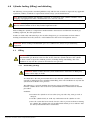
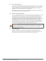
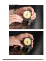
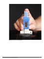
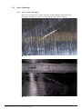
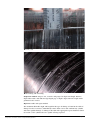
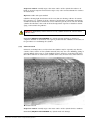
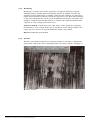
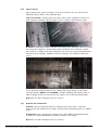
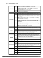
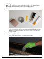
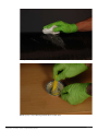
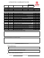
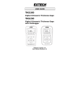
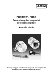
1
s o p m o C arbon C r e d n i l ite Cy ual n a M r s r e e d s n i l y U native Fuel C Alter dic o i r e p and e ers c d n n a i l n y e t c AF main e t , i e s s o u p om the c o t n o e b d r i Gu er ca f x u L f no o i t c e p ins A guide to the use, maintenance and periodic inspection of Luxfer carbon composite AF cylinders Page 1 Table of Contents 1.0 Introduction . . . . . . . . . . . . . . . . . . . . . . . . . . . . . . . . . . . . . . . . . . . . . . . .3 1.1 Distribution and proper use of this manual . . . . . . . . . . . . . . . . . . 3 2.0 Product description . . . . . . . . . . . . . . . . . . . . . . . . . . . . . . . . . . . . . .4 3.0 Cylinder handling, storage and installation . . . . . . . . . . . . . . . . . .5 3.1 Handling . . . . . . . . . . . . . . . . . . . . . . . . . . . . . . . . . . . . . . . . . . . . . .5 3.2 Storage . . . . . . . . . . . . . . . . . . . . . . . . . . . . . . . . . . . . . . . . . . . . . . .5 3.3 Installation . . . . . . . . . . . . . . . . . . . . . . . . . . . . . . . . . . . . . . . . . . . . 5 3.3.1 Cylinder installation and protection . . . . . . . . . . . . . . . . . . . .5 3.3.2 Mounting cylinders . . . . . . . . . . . . . . . . . . . . . . . . . . . . . . . 6 3.3.3 Strap or band (“belly”) mounting . . . . . . . . . . . . . . . . . . . . . .6 3.3.4 Neck mounting . . . . . . . . . . . . . . . . . . . . . . . . . . . . . . . . . . 7 3.4 Valve and pressure-relief (PRD) installation and removal . . . . . . . . 7 3.4.1 Valve installation . . . . . . . . . . . . . . . . . . . . . . . . . . . . . . . . . 7 3.4.2 Valve removal . . . . . . . . . . . . . . . . . . . . . . . . . . . . . . . . . . .8 3.4.3 Pressure relief device (PRD) . . . . . . . . . . . . . . . . . . . . . . . . .9 4.0 Cylinder filling (fueling) and defueling . . . . . . . . . . . . . . . . . . . . . . .10 4.1 Filling . . . . . . . . . . . . . . . . . . . . . . . . . . . . . . . . . . . . . . . . . . . . . . . . 10 4.1.1 Initial filling (fueling) . . . . . . . . . . . . . . . . . . . . . . . . . . . . . .10 4.1.2 Standard fill . . . . . . . . . . . . . . . . . . . . . . . . . . . . . . . . . . . . 11 4.2 Defueling . . . . . . . . . . . . . . . . . . . . . . . . . . . . . . . . . . . . . . . . . . . . . 11 5.0 Inspection. . . . . . . . . . . . . . . . . . . . . . . . . . . . . . . . . . . . . . . . . . . . . . . . . .12 5.1 Mounting inspection . . . . . . . . . . . . . . . . . . . . . . . . . . . . . . . . . . . . .12 5.2 Fuel system inspection . . . . . . . . . . . . . . . . . . . . . . . . . . . . . . . . . . .12 5.3 Cylinder inspection . . . . . . . . . . . . . . . . . . . . . . . . . . . . . . . . . . . . . .12 5.3.1 General system inspection . . . . . . . . . . . . . . . . . . . . . . . . . . 13 5.3.2 Periodic recertification inspection . . . . . . . . . . . . . . . . . . . . .13 5.3.3 Inspection training . . . . . . . . . . . . . . . . . . . . . . . . . . . . . . . .13 5.4 Recommended equipment . . . . . . . . . . . . . . . . . . . . . . . . . . . . . . . . 14 5.4.1 Inspection tools . . . . . . . . . . . . . . . . . . . . . . . . . . . . . . . . . .14 5.4.2 Cut measurement . . . . . . . . . . . . . . . . . . . . . . . . . . . . . . . . .15 5.4.3 Abrasion measurement . . . . . . . . . . . . . . . . . . . . . . . . . . . . .16 5.5 Types of damage . . . . . . . . . . . . . . . . . . . . . . . . . . . . . . . . . . . . . . . .18 5.5.1 Cuts, scratches and gouges . . . . . . . . . . . . . . . . . . . . . . . . . .18 5.5.2 Fire and heat damage . . . . . . . . . . . . . . . . . . . . . . . . . . . . . .20 5.5.3 Chemical attack . . . . . . . . . . . . . . . . . . . . . . . . . . . . . . . . . .21 5.5.4 Weathering . . . . . . . . . . . . . . . . . . . . . . . . . . . . . . . . . . . . .22 5.5.5 Abrasion . . . . . . . . . . . . . . . . . . . . . . . . . . . . . . . . . . . . . . .22 5.5.6 Impact damage . . . . . . . . . . . . . . . . . . . . . . . . . . . . . . . . . .24 5.5.7 Disbond and delamination . . . . . . . . . . . . . . . . . . . . . . . . . .24 5.6 Table of damage levels . . . . . . . . . . . . . . . . . . . . . . . . . . . . . . . . . . .25 6.0 Repair . . . . . . . . . . . . . . . . . . . . . . . . . . . . . . . . . . . . . . . . . . . . . . . . . . . . . .26 6.1 Repair tools . . . . . . . . . . . . . . . . . . . . . . . . . . . . . . . . . . . . . . . . . . . .26 6.2 Repair procedure . . . . . . . . . . . . . . . . . . . . . . . . . . . . . . . . . . . . . . . 26 6.3 Repairing delamination . . . . . . . . . . . . . . . . . . . . . . . . . . . . . . . . . . 29 7.0 Destruction of condemned or expired cylinders . . . . . . . . . . . . . . .30 8.0 Summary . . . . . . . . . . . . . . . . . . . . . . . . . . . . . . . . . . . . . . . . . . . . . . . . . . .34 Appendix 1: Cylinder label . . . . . . . . . . . . . . . . . . . . . . . . . . . . . . . . . . . . . .35 Appendix 2: AF Cylinder Inspection Form . . . . . . . . . . . . . . . . . . . . . . . .36 A guide to the use, maintenance and periodic inspection of Luxfer carbon composite AF cylinders Page 2 1.0 Introduction Luxfer carbon composite fully wrapped (Type 3) and hoop-wrapped (Type 2) cylinders are among the lightest gas cylinders available for alternative fuel applications. These products, which meet the needs of many end users in alternative fuel (AF) applications, offer a lightweight storage solution for compressed natural gas (CNG). High-pressure carbon composite cylinders are designed to be durable for the demanding usage they receive. Nevertheless, like all compressed gas equipment components, cylinders must be well maintained and properly used. This guide is intended to assist trained personnel in safely operating, valving, installing and inspecting Luxfer composite AF cylinders. You must be familiar not only with your equipment manufacturer’s instructions about properly and safely filling your Luxfer composite cylinders, but also with all applicable filling guidelines, regulations, requirements and laws of all appropriate local and/or national authorities and industry organizations. Luxfer carbon composite cylinder design, development, qualification, manufacturing and testing are conducted by Luxfer’s Alternative Fuel Cylinder Division in Riverside, California USA. 1.1 Distribution and proper use of this manual This document must be provided to all parties involved in distributing, handling, installing, inspecting and using Luxfer composite AF cylinders. The manual may be reproduced to provide sufficient copies for this purpose, but its contents must not be altered in any way. Luxfer accepts neither responsibility nor liability for consequences resulting from unauthorized alternations to this manual or for failure to follow the instructions herein. Document : v1.2 Copyright © 2008 by Luxfer Inc. All rights reserved. Except as permitted under the U.S. Copyright Act of 1976 and under provisions cited in paragraph 1.1, above, no part of this book may be reproduced in any form without the express written consent of Luxfer Inc. Published in the USA by Luxfer Inc. 3016 Kansas Avenue, Riverside, CA 92507 USA tel: (951) 684-5110 • Fax: (951) 781-6596 www.luxfercylinders.com A guide to the use, maintenance and periodic inspection of Luxfer carbon composite AF cylinders Page 3 2.0 Product description Type 3 AF cylinder Type 2 AF cylinder A guide to the use, maintenance and periodic inspection of Luxfer carbon composite AF cylinders Page 4 3.0 Cylinder handling, storage and installation Use the following guidelines to install Luxfer AF cylinders into vehicles. 3.1 Handling To prevent cylinder damage, Luxfer recommends the following: • Only handle AF cylinders with equipment that will not cause damage. • Do not handle cylinders with internal pressure above 3 bar (40 psi). • Do not drag, drop or roughly handle cylinders. • Protect cylinder labels to ensure legibility. • When transporting a valved cylinder, protect the valve and properly secure the cylinder. Never handle cylinders by their fittings, valves, pressure relief devices or piping. 3.2 Storage Store cylinders in a dry environment at temperatures between –40°F and 180°F (–40°C and 82°C). Protect cylinders from contaminants and damage. Short-term storage (less than six months)—Prevent the cylinder or assembly from rolling. Store at room temperature in a dry place away from chemicals, heat sources and corrosive environments. Place caps or plugs on cylinder or valve outlets to keep the cylinder and assembly clean and dry and to prevent moisture, dust or debris from entering the cylinder. Long-term storage (six months or more)—Install the valve and O-ring according to the valve manufacturer’s recommendations (see section 3.4). Store the valved cylinder at room temperature in a dry environment and properly protect the valve from damage. Store the cylinder with a small amount of positive pressure (not more than 3 bar or 40 psi). Protect the cylinder from chemicals, artificial heat sources and corrosive environments. (When a valve is not installed, place caps or plugs on outlets to keep the cylinder and assembly clean and dry and to prevent moisture, dust or debris from entering the cylinder.) 3.3 Installation 3.3.1 Cylinder installation and protection When the cylinder is installed on a vehicle, use shielding to protect the cylinder from damage caused by road debris and contact with vehicle components and cargo. The preferred shielding is open mesh, which not only protects the cylinder, but also permits easy reading of cylinder labels. To prevent cylinder damage: • Avoid direct contact between the shielding and the cylinder. • Avoid trapping solid debris or liquids between the shielding and the cylinder. • Avoid cylinder contact with vehicle components (e.g., brake lines, etc.). • Avoid exposure to vehicle heat. • Avoid exposure to harmful liquids and gases. • Avoid prolonged exposure to sunlight. A guide to the use, maintenance and periodic inspection of Luxfer carbon composite AF cylinders Page 5 3.3.2 Mounting cylinders Various mounting methods may be used with Luxfer cylinders. The mounting method and appropriate mounting hardware are often specified by the fuel system manufacturer and may be supplied by Luxfer. While typical, the sample mounting methods and parts list shown below are provided for general information only and do not overrule or supersede requirements of fuel storage system manufacturers or specific instructions provided either by system manufacturers or Luxfer for particular mounting configurations. Refer to applicable instructions and specifications provided by the fuel system manufacturer before attempting to mount cylinders. CAUTION: During pressurizing and de-pressurizing of a composite cylinder, it is normal for the cylinder to expand and contract. The chosen mounting system must allow for this expansion and contraction; otherwise, damage to the cylinder and fuel storage system may occur. 3.3.3 Strap or band (“belly”) mounting Figure 3.3.3 Minimum dimensions: A = 25mm (0.984”), B = 1/3 of cylinder length PARTS LIST Item Description 1 Composite cylinder 2 Belly mounting strap 3 Rubber strip† CAUTION: When using the strap or “belly” mounting method, a strip of rubber must be installed between the cylinder and metal straps to protect the carbon composite exterior of the cylinder. The mounting should also be sufficiently flexible to allow for longitudinal cylinder expansion and contraction. A guide to the use, maintenance and periodic inspection of Luxfer carbon composite AF cylinders Page 6 3.3.4 Neck mounting Figure 3.3.4 PARTS LIST Item Description 1 Composite cylinder 2 Fixed neck block 3 Sliding neck block 4 Bushing 5 Bolt 6 Washer Visually inspect end-mounting blocks regularly for signs of corrosion and premature wear. When lubrication of the neck block is required, use an aluminum-compatible, silicon-based lubricant. 3.4 Valve and pressure-relief device (PRD) installation and removal Use only approved valves and pressure-relief devices that comply with applicable standards and regulations (e.g., NGV 3.1 and PRD-1). A list of approved valves is available at www.luxfercylinders. com. WARNING: Do not use valves or pressure-relief devices that have not been tested and approved by Luxfer. 3.4.1 Valve installation Inspect the valve in accordance with the valve manufacturer’s recommendations prior to installation. Do not install any valve that has not passed such an inspection. The valve threads should be free from damage. Use appropriate gauges to ensure that threads comply with specifications. Ensure that the mating surface on the valve is smooth and free from damage. Damaged or distorted valve threads can damage cylinder threads. Damage to the mating surface can prevent sealing and can damage the sealing surfaces of the cylinder. A guide to the use, maintenance and periodic inspection of Luxfer carbon composite AF cylinders Page 7 Check to make sure that the O-ring groove and threads in the cylinder are clean and free from damage. Install a new O-ring on the valve in accordance with the valve manufacturer’s recommendations. Luxfer recommends lubricating the O-ring prior to installation with a lubricant compatible with the O-ring material. Apply a small amount of aluminum-compatible, silicon-based lubricant to the bottom three valve threads, taking care not to apply lubricant to the bottom face of the valve body. Only a thin application of lubricant is necessary—too much lubricant can cause sealing problems. Insert the valve into the cylinder neck and tighten it by hand to make sure threads are properly aligned. Then tighten the valve to the torque value recommended by the valve manufacturer. Note: Valve torque guidelines in the table below are provided for general information only and do not overrule or supersede valve manufacturers’ torque-level recommendations, which should be used in preference to the values shown. Table 1—Valve torque guidelines VALVE TORQUE VALUE TABLE Thread Min. N-m (ft.lb.) Max. N-m (ft.lb.) 1.125 – 12 UNF 129 (95) 176 (130) 2.00 – 12 UNF 271 (200) 339 (250) 3.4.2 Valve removal In a well-ventilated area, slowly open the valve to release pressure from the cylinder. When the cylinder is completely empty of pressurized gas (see section 4.2), remove the valve, using proper tools in accordance with the valve manufacturer’s guidelines. During this process, secure the cylinder so that cylinder fibers and the valve are not damaged. WARNING: If the valve is hard to remove, STOP. If you suspect for any reason that a valve may be defective, do not attempt to remove the valve—because a valve that is damaged or not functioning properly may cause you to think erroneously that the cylinder is empty when you do not hear gas being released. Handle all valved cylinders— even those you think are empty—as if they were under pressure! To check whether a hard-to-remove valve is functioning properly, add to the cylinder a small amount of the gas specified on the cylinder label to prove that gas actually goes in and out of the valve. If the valve works properly during this check, fully depressurize the cylinder and then carefully remove the valve. If you have questions about valve function or require further instructions, contact the valve manufacturer. Once the valve is removed, inspect it thoroughly. Check valve threads for damage and inspect cylinder threads to verify that they are clean-cut and undamaged. Clean the cylinder O-ring gland (groove). REJECT cylinders with damaged threads. REJECT cylinders with O-ring gland damage that prevents an effective, safe seal. A guide to the use, maintenance and periodic inspection of Luxfer carbon composite AF cylinders Page 8 3.4.3 Pressure-relief device (PRD) Use only approved pressure-relief devices that comply with applicable standards and regulations (e.g., PRD-1). Visit www.luxfercylinders.com for a list of PRDs and proper configurations. Some PRDs are integrated into the valve, while others must be installed separately. If a vent line is required to vent gas away from the cylinder, take note that no valves or flow restrictions are allowed anywhere in the inlet or outlet flow path of a PRD. Below are sample PRDs installation methods. Single PRD configuration—Where only a single PRD is required, use one of the following configurations approved by Luxfer for the specific cylinder model being considered: CNG valve with an integrated PRD Valve with a retrofitted PRD Separate end-plug PRD Double PRD configuration—Where a double PRD configuration is required, use either a CNG valve with an integrated PRD or a valve with a retrofitted PRD in combination with a separate end-plug PRD. Multiple PRD configuration—Figure 3.4.3 (below) is an example of a cylinder configured with three PRDs—one integrated in the valve, a second end-plug PRD in the opposite cylinder end and a third, L-shaped PRD piped from the valve to a central position. Additional T-shaped PRDs could also be installed in series along the pipe from the valve. Figure 3.4.3 General guidelines that apply to all PRD installations: • Ensure that threads are undamaged. • Clean threads thoroughly. • Dry threads and ensure that the area is free from debris. • Select the proper O-ring or copper-crush washer specified by the PRD manufacturer. • If recommended by the PRD manufacturer, apply lubricant to the O-ring or copper-crush washer. • Place the O-ring or copper crush-washer properly on the fitting, being careful not to damage the O-ring or copper crush-washer. • Thread the fitting into the mating surface. • Apply the proper installation torque recommended by the PRD manufacturer. A guide to the use, maintenance and periodic inspection of Luxfer carbon composite AF cylinders Page 9 4.0 Cylinder fueling (filling) and defueling The following section provides standard guidelines only and does not overrule or supersede any applicable regulations, industry standards or requirements of fuel storage system manufacturers. Note: During fueling (filling) and defueling, expansion or contraction of the cylinder sometimes causes snapping or popping noises. This is normal and is not a cause for concern. WARNING: Always ground (earth) the cylinder, fuel system or vehicle whenever cylinders are being filled or defueled. Failure to do so may result in explosion or fire. Prior to filling the cylinder, it is important to understand the characteristics and hazards of natural gas, including explosion, fire and asphyxiation. In order to work safely with natural gas, do not allow dangerous gas concentrations to form within a working environment. Test all systems in a well-ventilated area that is free from ignition sources. WARNING: When working with flammable gases in a confined area, always use gas-monitoring equipment. 4.1 Filling WARNING: Always remove all oxidants (including air) from a cylinder prior to filling the cylinder with flammable gas! Be alert to the fact that air may enter the cylinder whenever the cylinder has been vented or exposed to ambient pressure, including during initial filling, after valve installation or any time the system has been bled to zero pressure. 4.1.1 Initial filling (fueling) WARNING: Failure to follow the fuel system manufacturer’s instructions on filling may lead to serious injury or death! An “initial fill” is the first pressurization that occurs after the cylinder has been vented or exposed to ambient pressure, including initial filling, after valve installation or any time the system has been bled to zero pressure. The following is a general guideline for removing oxygen (including oxygen in air) from the cylinder. Please refer to the fuel system manufacturer’s instructions for detailed procedures. Guideline: 1. Pressurize the cylinder to at least 5 bar (72.5 psi) with a dry, inert gas such as nitrogen. 2. Vent the cylinder slowly to avoid any condensation in the cylinder or valve. 3. Once the system has been vented, close the valve to prevent air from re-entering the cylinder. The cylinder may now be filled with natural gas in accordance with the fuel system manufacturer’s instructions. A guide to the use, maintenance and periodic inspection of Luxfer carbon composite AF cylinders Page 10 4.1.2 Standard fill CAUTION: North American users—Fill the cylinder such that the settled pressure does not exceed the marked service (working) pressure at 21°C (70°F). All other regions—Fill the cylinder such that the settled pressure does not exceed the marked service (working) pressure at 15°C (60°C). 4.2 Defueling WARNING: When working with flammable gases in a confined area, always use gas-monitoring equipment and ground (earth) all equipment. During defueling, make sure pressure is sufficiently low that those performing the procedure will not be harmed if gas escapes due to a leak or broken seal. However, defueling pressure must be slightly higher than atmospheric pressure to stop air from entering the cylinder if a seal is broken. Vent gas properly through a flue or flare stack to prevent contaminating the environment and to avoid a potentially hazardous gas accumulation. Always make sure that all equipment is properly grounded (earthed). A guide to the use, maintenance and periodic inspection of Luxfer carbon composite AF cylinders Page 11 5.0 Inspection Using proper equipment and safety apparatus, inspect cylinders routinely to determine whether damage has occurred. Thoroughly clean cylinders with a mild soap-and-water solution before inspecting. Do not use solvents, harsh cleaners or abrasives. Always carefully inspect cylinders if a vehicle has been involved in an accident. 5.1 Mounting inspection Ensure that all mounting blocks, brackets and other components are in good condition and properly secured. If any mountings are loose, re-tightened them by following procedures specified by the fuel system manufacturer. If a mounting is damaged, you must conduct a re-certification inspection. If parts are missing or need replacement, please contact the fuel storage system manufacturer. 5.2 Fuel system inspection CAUTION: Never allow air or debris to enter a cylinder. When disconnecting fittings (seals) during maintenance or inspection, make sure that air or debris do not enter through the opening. Fuel system inspection includes checking all attached components, such as valves, tubing, end plugs, fittings and pressure-relief devices. During inspection, make sure that each device is securely attached. If any is loose, tighten it in accordance with the fuel system manufacturer’s instructions. If any component is missing, contact the fuel storage system manufacturer and do not put the system back into service. 5.3 Cylinder inspection IMPORTANT: The Luxfer-recommended “accept” and “reject” criteria provided in this manual do not replace or supersede any criteria established by regulatory authorities either now or in the future. Alternative fuel cylinders are designed and manufactured for a limited design life, which is indicated on the cylinder label. Always check the label first to ensure that the cylinder has not exceeded its expiration date. REJECT and remove from service any cylinder that either lacks a label containing mandatory information or has a label that has become illegible. If you can positively determine that Luxfer produced such a cylinder and you know the cylinder serial number, contact Luxfer for disposition instructions. Inspect for the following conditions during periodic inspection: • Cuts, scratches and gouges • Fire and heat damage • Chemical attack • Debonding • Delamination • Weathering • Abrasion • Impact damage A guide to the use, maintenance and periodic inspection of Luxfer carbon composite AF cylinders Page 12 5.3.1 General system inspection This inspection, usually performed by a driver, maintenance person or service technician, is a basic visual inspection to ensure that the cylinder and mountings are in good condition. The inspection includes, as a minimum, examining the mounting system, cylinder and plumbing, as well as checking for gross leaks and damage. Perform this inspection at least every three months under normal operating conditions and more frequently during more demanding conditions. 5.3.2 Periodic recertification inspection This is an in-depth examination of the cylinder, mounting system and plumbing for external damage and deterioration, including the cylinder surface under the support straps. A competent agency or person approved or recognized by applicable regulatory authorities must conduct the inspection in accordance with all applicable regulations and Luxfer specifications. Under normal operating conditions, perform the inspection every three years or 36,000 miles, whichever comes first. In addition, you must perform a recertification inspection following any accident or fire, as well as at the time of any reinstallation. (This recertification inspection is mandatory under most CNG cylinder and system standards; however, the prescribed frequency may vary from standard to standard.) IMPORTANT: For the lifetime of a cylinder, records of all periodic recertification inspections and testing should be sent to Luxfer along with materials, test certificates and inspection reports relating to the manufacture of the cylinder. Such record-keeping is required by regulatory authorities. 5.3.3 Inspection training Luxfer Gas Cylinders offers inspection training either at its AF facilities in Riverside, California, on site at customer locations or periodically at special training venues (watch www.luxfercylinders.com for announcements of upcoming training sessions). A guide to the use, maintenance and periodic inspection of Luxfer carbon composite AF cylinders Page 13 5.4 Recommended equipment 5.4.1 Inspection tools A mirror and a flashlight are helpful when you are inspecting hard-to-reach areas. Bubbling leakdetection fluid is also useful. (Optional: A digital camera can be used to document damaged areas.) Fill out an inspection report form (available from Luxfer.) If a cylinder is irreparably damaged, apply a “Danger: Failed Cylinder Inspection” label to cylinder. If the cylinder passes inspection, apply a label showing the date of the inspection. A guide to the use, maintenance and periodic inspection of Luxfer carbon composite AF cylinders Page 14 5.4.2 Cut measurement Cut measurement—First calibrate the depth gauge to zero on the undamaged cylinder surface. Then measure the depth of the cut. A guide to the use, maintenance and periodic inspection of Luxfer carbon composite AF cylinders Page 15 5.4.3 Abrasion measurement Abrasion measurement—Calibrate the depth gauge to zero on the undamaged cylinder surface (left), then measure the depth of the abrasion at the deepest point (right). A guide to the use, maintenance and periodic inspection of Luxfer carbon composite AF cylinders Page 16 You may also use a digital depth gauge. A guide to the use, maintenance and periodic inspection of Luxfer carbon composite AF cylinders Page 17 5.5 Types of damage 5.5.1 Cuts, scratches and gouges These are easily spotted on carbon composite cylinders. Watch for fiber lifting and unraveling caused by cuts transverse to the direction of the fiber wrapping. Level 1 cut Level 2 cut A guide to the use, maintenance and periodic inspection of Luxfer carbon composite AF cylinders Page 18 Level 3 cut Fiber lifting and unraveling Inspection method—Inspect cuts, scratches and gouges for depth and length. Measure depth either with a dial indicator-type depth gage or depth caliper. Measure length with a graduated scale or ruler. Reference: Table and repair method. The maximum allowable depth and length for this type of damage is found in the table of damage levels in section 5.6; immediately remove from service and condemn any cylinder with unacceptable damage according to this table. The appropriate repair method is found in Section 6.1 for cylinders that are capable of being repaired. A guide to the use, maintenance and periodic inspection of Luxfer carbon composite AF cylinders Page 19 5.5.2 Fire and heat damage Heat damage—Elevated heat exposure, which is a different condition than obvious heat or fire damage, may or may not result in permanent damage to the cylinder. Elevated heat exposure occurs when the cylinder itself (apart from any outer protection) has been subjected to a temperature in excess of the glass-transition temperature or softening point of the composite material (expressed as Tg). A composite cylinder is not intended for normal use in any environment resulting in prolonged composite overwrap temperatures in excess of 82°C (180°F). Prolonged temperatures in excess of the Tg of the composite may cause discoloration of the resin system. This discoloration may range from a light golden caramel color to a deep brownishblack burnt appearance. Harmless natural aging—i.e., light discoloration of the external coating, usually a yellowing over time due to continued direct exposure to sunlight—is not the result of harmful temperature exposure. Usually the degree and depth of resin discoloration are dependent on the temperature, the duration of exposure or a combination of both. The higher the temperature, or the longer the duration of exposure to a lower temperature, the darker the resin system will become. If you are uncertain about the cause of resin discoloration, contact Luxfer for guidance. Fire damage—Charring or melting of the composite material, decals, valves or other attachments is evidence of fire damage. Full or partial activation of the PRD is also evidence of fire or excessive heat. Flame impingement may result in the resin burning away from the cylinder exterior, leaving loose carbon fibers. Fire Damage A guide to the use, maintenance and periodic inspection of Luxfer carbon composite AF cylinders Page 20 Inspection method—Visually inspect the entire surface of the cylinder for evidence of burnt or charred composite material. Also inspect any valves and attachments for evidence of extreme heat. Reference: Table and repair method. Cylinders showing light discoloration of the resin, but not showing evidence of extreme heat exposure (e.g., melting of decals, charring or heat damage to mounting attachments or PRD activation), may be returned to service without repair. If you are not sure whether cylinder discoloration is the result of elevated temperature exposure or harmless natural aging, contact Luxfer for guidance. WARNING: Immediately remove from service any cylinder involved in a motor vehicle collision or fire. Immediately REJECT and CONDEMN any cylinder showing melting or charring of composite material or attachments. No repair is possible for this condition. See Section 7.0 for procedures on condemning the cylinder. 5.5.3 Chemical attack Chemicals, including battery acid (to which AF cylinders may be exposed), may dissolve, corrode, soften, remove or ruin cylinder materials; they may also cause bubbling, pitting or extreme dulling of the resin or create multiple fractures transverse to the direction of the fiber. When solvents are involved, the cylinder surface may become sticky when touched. Chemical attack Inspection method—Visually inspect the entire surface of the cylinder for this condition. Immediately REJECT and CONDEMN any cylinder with such damage. A guide to the use, maintenance and periodic inspection of Luxfer carbon composite AF cylinders Page 21 5.5.4 Weathering Weathering is a change in the surface appearance of composite material or exposed aluminum surfaces resulting from environmental exposure to sunlight, road salts and extreme heat and cold. Exposure to sunlight can discolor the composite over time; this is usually characterized by a yellowish color in the exposed area (see “Heat and fire damage,” section 5.5.2). Road salts may corrode exposed aluminum, but this does not usually cause damage to composite material. Extreme heat or cold may cause mild discoloration of the composite or craze-cracking of the surface resin. Inspection method—Visually inspect the entire surface of the cylinder for weathering. Discoloration or craze cracking of the resin is classified as Level 1 damage and does not require repair. If corrosion of exposed aluminum is found, contact Luxfer. Reference: Table and repair method. 5.5.5 Abrasion Abrasion, or localized wearing away of composite material, occurs when a cylinder rubs against other components such as mounting brackets, the vehicle structure, shielding, etc. Level 1 abrasion A guide to the use, maintenance and periodic inspection of Luxfer carbon composite AF cylinders Page 22 Level 2 abrasion Level 3 abrasion Inspection method—Visually inspect the entire surface of the cylinder for evidence of abrasion. Pay close attention to areas around mounting straps or other attachments. Reference: Table and repair method. Refer to Table 5.6 for damage limits for abrasion. Immediately REJECT and CONDEMN any cylinders with unacceptable damage according to this table. A guide to the use, maintenance and periodic inspection of Luxfer carbon composite AF cylinders Page 23 5.5.6 Impact damage Impact damage may appear as hairline cracks in the exterior resin, cuts, abrasion and indentation of the surface of the aluminum liner. Inspection method—Visually inspect the entire surface of the cylinder for evidence of impact damage. Carefully evaluate all impact sites according to the following criteria: LEVEL 1: Light impact damage that does not require repair. It usually consists of a small area where the composite is frosted. Where impact results in cuts or abrasion, evaluate these features according to the table of damage levels in section 5.6 for the maximum area allowed for Level 1 damage. Cylinders with Level 1 damage can usually be returned to service. LEVEL 3: Severe damage in which impact has caused a large area of frosting (including cuts or abrasion), damage to fibers in the cylinder dome, liner denting or other major structural damage. REJECT and CONDEMN a cylinder exhibiting such damage. Refer to table of damage levels in section 5.6 for Level 3 impact, cut or abrasion damage limits. Reference: See table of damage levels in section 5.6. 5.5.7 Disbond and delamination Disbond is physical separation between composite layers (most often a separation between glass and carbon layers). Usually caused by impact, disbond appears as a whitish region. Delamination is the separation of composite layers, but it differs from disbond in that cut fibers are evident. Delamination is usually caused by severe impact. Reference: See table of damage levels in section 5.6. A guide to the use, maintenance and periodic inspection of Luxfer carbon composite AF cylinders Page 24 5.6 Table of damage levels Abrasion Level 1 Any size area of abrasion less than 0.01” (0.254mm) deep. Level 2 Any abrasion between 0.01” (0.254mm) and 0.03” (0.762mm) deep and less than 1.0 sq.in. (645.16mm2) in area. Level 3 Any abrasion exceeding level 2. Level 1 Any number of flaws of any length less than 0.01” (0.254mm) deep. Level 2 Cut / Gouge Any number of flaws of any length between 0.01” (0.254mm) and 0.03” (0.762mm) deep. OR one single flaw between 0.03” (0.76mm) and 0.05” (1.27mm) deep and less than 1.0” (25.4mm) long. Any flaw greater than 0.03” (0.762mm) deep and greater than 1.0” (25.4mm) long. Level 3 OR multiple flaws between 0.03” (0.762mm) and 0.05” (1.27mm) deep and less than 1.0” (25.4mm) long. OR any flaw greater than 0.05” (1.27mm) deep. Impact Level 1 A small, frosted and whitish area less than 1.5 sq.in. Level 2 N/A. Level 3 Any impact damage exceeding level 1 (liner indentation, fiber delamination in dome area, major structural damage). Level 1 Disbonding is allowed between the outer glass wrap and the carbon, since the glass wrap is for protection only. All disbonding needs to be checked to ensure that it is not caused by impact. Level 2 N/A. Level 3 N/A (see impact). Level 1 N/A. Level 2 Limited to outer hoop only. Width of delamination may not be wider than original damage from cut, gouge or abrasion. Level 3 Any delamination exceeding level 2. Level 1 Light discoloration. Level 2 N/A. Level 3 Evidence of burnt or charred resin. (967.74sqmm) in area. Disbond Delamination Fire / Heat A guide to the use, maintenance and periodic inspection of Luxfer carbon composite AF cylinders Page 25 6.0 Repair Note: It is not possible to repair cylinders showing evidence of chemical attack, fire and heat damage. Refer to Section 7.0 for instructions on condemning cylinders with these conditions. 6.1 Repair tools These tools are needed to repair Level 2 damage (left to right): 120-grit (fine) sandpaper, a receptacle for mixing epoxy resin, a resin applicator, two-part epoxy resin (resin plus cure) and a brush that may be needed for removing dust and debris. Clean shop rags or heavy-duty paper towels are also useful. 6.2 Repair procedure For any cylinder with Level 2 damage, use the following repair procedure. Clean and sand damaged area with 120-grit (fine) sandpaper. A guide to the use, maintenance and periodic inspection of Luxfer carbon composite AF cylinders Page 26 Wipe off sanding dust. Mix epoxy resin, following manufacturer’s instructions. A guide to the use, maintenance and periodic inspection of Luxfer carbon composite AF cylinders Page 27 Apply resin to damaged area, ensuring that resin is worked fully into any damage. Allow to dry, following manufacturer’s instructions. Optional steps to improve cylinder appearance: Optional: When the epoxy is fully cured and dried, sand the surface again. A guide to the use, maintenance and periodic inspection of Luxfer carbon composite AF cylinders Page 28 Optional: Apply clear gloss air-dry acrylic enamel to the repaired area. 6.3 Repairing delamination Trim off delaminated fiber at the widest and deepest point. Note: Only delamination of the outer hoop wrapping may be repaired. The width of the delamination may not be any wider than the original area of damage from cuts, gouges or abrasion (see section 5.6, above). A guide to the use, maintenance and periodic inspection of Luxfer carbon composite AF cylinders Page 29 Measure the width of the clipped segment to make sure that the delaminated area is within acceptable limits for repair. A guide to the use, maintenance and periodic inspection of Luxfer carbon composite AF cylinders Page 30 Also measure the thickness of the clipped segment to ensure that it is meets the criteria for repair shown in table 5.6, above. A guide to the use, maintenance and periodic inspection of Luxfer carbon composite AF cylinders Page 31 Follow the procedures shown on page 27, above, to mix epoxy resin. Generously apply resin to the gap left when delaminated fiber was removed from the outer hoop-wrapping. Continue applying resin until the gap left by delamination is completely filled. Allow to dry, following manufacturer’s instructions. A guide to the use, maintenance and periodic inspection of Luxfer carbon composite AF cylinders Page 32 There should be no indentations or low spots in the repaired area, which should extend slightly above the original surface of the cylinder. A guide to the use, maintenance and periodic inspection of Luxfer carbon composite AF cylinders Page 33 7.0 Destruction of condemned or expired cylinders To destroy condemned or expired cylinders, drill a minimum 1/2-inch (13mm) hole all the way through the cylinder wrapping and liner so that the cylinder cannot hold gas. WARNING: Even if completely vented, the cylinder will contain a significant amount of residual flammable gas that could ignite! Completely purge the cylinder with an inert gas (such as nitrogen) before destroying it. Do not use compressed air to purge the cylinder! Always dispose of condemned or expired cylinders in accordance with current NGV-2 guidelines. 8.0 Summary 8.1 Care and maintenance ALWAYS: Always be alert for leaks with each fill. Always keep the threads and cylinder interior dry and free from oil, dirt and other contaminants. Always fill cylinders with the proper gas. Always follow inspection recommendations. Always follow the fuel system manufacturer’s procedures and recommendations. Always follow the valve manufacturer’s installation procedures and recommendations. Always maintain all accessory equipment in accordance with the manufacturer’s recommendations. NEVER: Never fill a cylinder if it leaks. Never fill a cylinder with a defect. Never completely discharge a cylinder (except when you’re planning to remove the valve), since this can cause moist air to seep into the cylinder. Never fill or partially fill a cylinder with any gas not identified on the label. Never artificially heat your cylinder. Never fill a cylinder that is past its required periodic recertification inspection date. Never fill a composite cylinder past its allowable life. Never over-torque a valve. Never remove, obscure or alter a manufacturer’s labels or stamped markings. Never use a cylinder after it has been exposed to an extremely corrosive atmosphere or environment, without having it pass the periodic recertification inspection. Never use a cylinder that has been involved in a traffic accident or a fire. A guide to the use, maintenance and periodic inspection of Luxfer carbon composite AF cylinders Page 34 Appendix 1: AF cylinder sample label. Appendix 2: AF cylinder inspection form (see next page) The AF Cylinder Inspection Form may be used as a master for copying additional forms. A guide to the use, maintenance and periodic inspection of Luxfer carbon composite AF cylinders Page 35 ALTERNATIVE FUEL CYLINDER INSPECTION FORM Date: Vehicle make Model VIN # Year Cylinder No: Manufacturer Serial # Location Label Serial # (Applied) NFPA 52 sect. 3-3 3-3 3-3 3-3 3-3 3-3 3-3 3-3 3-3 3-3 3-3 - GRI pg. 6-12 6-13 4-4 6-14 6-6 6-14 6-7 6-7 6-14 6-14 6-14 6-19 7-8 6-8 Sect - 7 3-3 2-5 3-4 2-8 3-5 6-13 6-13 7-2 Sect - 7 6-16 - 1 Mileage 2 4 3 P = Pass ALTERNATIVE FUEL CYLINDER EXAMINATION 1 Cylinder and mounting brackets are clean. Cylinder installation complies with NFPA-52. Minimum 1/2-inch clearance exists around cylinder and 3/8-inch clearance from shields Rubber mounting pads are in place and in good condition. Cylinder is firmly restrained by brackets (no looseness, rocking or cracks). All bracket securing bolts are present and tight. All bracket and strap bolts are torqued to proper specifications. Mounting brackets are in good condition and free from bends, deformations or damage Mounting bracket area is undamaged. Bracket-to-vehicle mounting shows no signs of stress. Brackets and straps are free from corrosion. Cuts, gouges and abrasions on the cylinder are less than 0.010 inch in depth. No signs of cylinder exposure to fire or extreme heat. No signs of cylinder damage from an accident. Cylinder is free from impact damage and shows no signs of surface discoloration, cracked resin, chipping or loose fibers. Cylinder service pressure markings are not less than vehicle service pressure. Cylinder has not exceeded its service life. Cylinder is properly externally vented (this applies only to cylinders enclosed in vehicles Cylinder is free from rust, corrosion or etching of the outer surface. External paint, composite layer and metal surfaces are free from bubbles or bulges. Valves, lines and/or pressure-relief devices (PRD) are damage free. Fuel and vent lines are properly attached to the vehicle. Vehicle history shows no incidents that may possibly have damaged the cylinder. New inspection sticker has been applied. 2 F = Fail 3 4 Summary of examination and description of damage and/or other adverse findings: Repaired or replaced brackets or other components as follows: CYLINDER INSPECTION RESULTS (check only one) Return cylinder(s) to service. Repair cylinder(s) as follows: Send cylinder(s) to manufacturer for further inspection as follows: REMOVE CYLINDER(S) FROM SERVICE AND DESTROY. Certificate No. A guide to the use, maintenance and periodic inspection of Luxfer carbon composite AF cylinders Inspector's signature Page 36