1
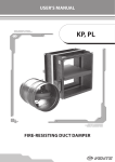
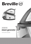
UPP System Integrity Testing Kit
Model VTU2
User Manual
Franklin Fueling Systems • 3760 Marsh Rd. • Madison, WI 53718 USA
Tel:  +1 608 838 8786 • 800 225 9787 • Fax: +1 608 838 6433 •
www.franklinfueling.com
1. Introduction
The UPP System integrity testing kit allows for precise testing of the tightness
of single wall underground tank chambers (sumps) and dispenser sumps.
The versatile unit can also be used to test double wall dispenser and tank
chambers and also the interstitial space in secondary contained (double wall)
pipe systems.
2. Safety Instructions
• The system integrity testing unit is designed specifically for use on fuelling
installations and should be protected against water and dust.
• The machine should be handled with the care usually given to sensitive
electrical equipment, especially during transport.
• Each time the machine is used, the condition of the machine, and especially
the power cable needs to be checked. If damage is discovered, the machine
needs to be returned directly to the supplier or an authorised service centre.
• Before connecting the machine, the power source needs to be checked with
regard to the rating of the test unit (230v or 110v - see specifications).
•Never pull and/or lift the machine by its power cable.
• The machine should only be operated outside of zone 2 areas (hose length
permits testing inside these areas even when the machine is situated outside)
IMPORTANT: Ensure that any storage tank is completely sealed and isolated
from the chamber whilst it is being tested. Tanks are not
designed to withstand a vacuum and damage may result.
3. Liability restrictions
In each of the following cases, all liabilities of the supplier are invalidated if:
•
•
•
•
•
2
The machine is used outside the indicated application area
The operator is not trained to use this machine
The recommended maintenance intervals are not observed
The safety instructions are not observed
Repairs have been performed by other than the supplier or their authorised
agent
4. Operating Instructions
The VTU2 is designed to automatically condition and test in one sequence
of operations. Conditioning is an essential step, when tightness testing
Polyethylene systems due to the flexible nature of the material, to ensure that
no false results are obtained. This is achieved by pulling a vacuum a total of
three times, resting and allowing the assembly to contract for 60 seconds after
the first and second evacuations and commencing the test proper after the third.
Figure 1: VTU2 Front Panel
To aid any necessary leak detection and remedial work, it is recommended that
UPP tank chambers are tested in specific stages during the installation process.
Test 1 - Testing the base of a two-piece tank chamber
After installing the tank chamber base, test for tightness as follows:
1. Make sure the vacuum lid gaskets and chamber base flange are clean
and free from dirt and debris.
2. Place the vacuum lid on to the chamber base.
3. Place the test unit outside zone 2 (if on a live site) but as close to the
chamber as possible and within 4 meters of an electrical power source.
4. Connect the hoses between the lid and the test unit, check that hose
ends are in good condition.
5. Make sure the test on / off switch is set to “0” position and connect the
power lead from the test unit to the power supply.
6. Select “Chamber / Sump” setting.
3
7. Set switch to Test On position and unit will go through calibration
process with coloured lights flashing.
8. When calibration is complete vacuum pump will run until the correct
test vacuum is reached, unit will commence conditioning and test
sequence. Test will commence after third pump run and blue test light
will be on.
9. When vacuum has been held for the required test period, the green
light will illuminate and the chamber can be considered leak-tight.
10. If the vacuum is not held then the red light will illuminate and the
chamber should be investigated using a leak detection liquid spray.
The only possible leak point should be the tank sump / chamber mounting
flange.
Once the chamber base is leak tight, install pipe-work and proceed to test 2.
Test 2 - Testing the base of a two-piece tank chamber (2)
After installing the seals and pipe runs, re-test the base for tightness. To test
the chamber base, follow these instructions:
1. Make sure the vacuum lid gaskets and chamber base flange are clean
and free from dirt and debris.
2. Place the vacuum lid on to the chamber base.
3. Place the test unit outside zone 2 (if on a live site) but as close to the
chamber as possible and within 4 meters of an electrical power source.
4. Connect the hoses between the lid and the test unit, check that hose
ends are in good condition.
5. Make sure the test on / off switch is set to “0” position and connect the
power lead from the test unit to the power supply.
6. Select “Chamber / Sump” setting.
7. Set switch to Test On position and unit will go through calibration
process with coloured lights flashing.
8. When calibration is complete, the vacuum pump will run until the
correct test vacuum is reached. The unit will then start the conditioning
and test sequence. Test will commence after third pump run. The blue
test light will be on.
9. When vacuum has been held for the required test period, the green
light will illuminate and the chamber can be considered leak-tight.
10. If the vacuum is not held then the red light will illuminate and the
chamber should be investigated using a leak detection liquid spray.
4
Possible leak points are:
• Pipe / seal interface
• Electrofusion / chamber interface
• Vacuum lid seal
• Conduit seals
• Vacuum pipe connections
Test 3 - Testing the chamber riser
1. Uncouple the hose connection from the vacuum lid and remove
the vacuum lid from the base section. Join the riser to the base
section as detailed in the relevant chamber installation instructions
(FFS document FFS-0129. On the web http://www.franklinfueling.
com/service. Select Service / Technical Documentation / Piping and
Containment).
2. Place appropriate test-lid on riser.
3. Connect vacuum hoses to riser lid.
4. Select Chamber / Sump test setting.
5. Re-run test as in test 1.
6. If the vacuum is not held, investigate the chamber using a leakdetection liquid spray. Possible leak points include:
•
•
•
•
Centre section seal
Vacuum lid seal
Riser seals
Vacuum pipe connections
Never set switch to “pressure test only” without prior
Caution
consultation with Franklin Fueling Systems. Serious
damage to the machine or chamber could result.
Never enter a chamber or sump whilst it is under vacuum
test as serious injury could result.
5
5. Vacuum Test Parameters
Setting
Vacuum
Time
Chamber / Sump
-30 mbar
7 minutes
Spill Bucket
-30 mbar
1.5 minutes
6. Fault Diagnosis
6
Fault
Solution
Vacuum level not reached or
keeps on falling
• Check and listen for leaks in all the areas
outlined in the tests. Rectify faults if found
Vacuum still falling. All areas
on chamber are leak tight
• Check containment collar flange
and fittings for leak path. Contact
tank manufacturer if leak is found for
alternative sealing solutions.
• Possible leak inside unit, contact FFS
customer support for full diagnostic
Vacuum equipment running
but no vacuum being
produced
• Check connection to vacuum lid and
pump. To check pump, block one end of
pipe and monitor the movement of the
vacuum gauge.
• Possible leak inside unit, contact FFS
customer support for full diagnostic
Pump not running
• Check power to unit and electrical fuse
7. Specifications
110v model
230v model
VTU2-110V
VTU2-230V
Voltage
100-110V
230V ± 10%
Frequency
50/60Hz
50/60Hz
145 W / 2.9A
145 W / 1.54A
Model designation
Power rating
Enclosure protection class
IP54
Operating temperature limits
0-50º C (32 - 122º F)
Fuse protection
Dimensions
5A anti-surge
420 mm x 250 mm x 280 mm
(16.5" x 9.8" x 11")
Weight
17.5 kg (38.6 lb.)
8. Accessories
Test Lids
Description
Chamber Test Lid Assy
Sump Test Lid Assy
Size mm
Model Designation
560 dia
VTL-560 DIA
1200 dia
VTL-1200 DIA
1350 dia
VTL-1350 DIA
800 x 800
VTL-800x800
1250 x 600
VTL-1250X600
1470 x 600
VTL-1470X600
All test lids supplied in a hard-wearing carry bag
7
Warranty Statement
The Franklin Fueling System Integrity Testing Kit is designed for use with
Franklin Fueling’s UPP product range.
This unit should always be used within the constraints and capabilities of the
equipment being tested. If you have any doubts as to the required settings for
UPP Systems please consult Franklin Fueling Systems at the address shown.
Should you wish to use this Integrity Testing Kit on other manufacturer’s
equipment, it is the responsibility of the user to check the capabilities of the
parts being tested prior to use of this equipment.
No liability will be accepted by Franklin Fueling Systems or its
distributors / agents for damage caused during tests carried out on other
manufacturers equipment.
It is the responsibility of the user to seek a disclaimer and indemnify against
damage caused by the use of this testing kit on other manufacturers
equipment.
Franklin Fueling Systems LTD
8 Olympus Close • Whitehouse Industrial Estate
Ipswich, Suffolk IP1 5LN • United Kingdom
Tel: +44 1473 243300 • Fax: +44 1473 243301
© 2012 FFS 408047001 Rev 1