1
ECE 477 Final Report Spring 2009
Team 13 Moto-eV
Team Members:
#1: Mike Stuckenschneider
Signature: ____________________ Date: _________
#2: Loren Garby
Signature: ____________________ Date: _________
#3: Arin Chakraverty
Signature: ____________________ Date: _________
#4: Janell Niekamp
Signature: ____________________ Date: _________
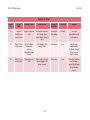
CRITERION
Technical content
Design documentation
Technical writing style
Contributions
Editing
Comments:
0
0
0
0
0
1
1
1
1
1
2
2
2
2
2
3
3
3
3
3
SCORE
4 5 6 7
4 5 6 7
4 5 6 7
4 5 6 7
4 5 6 7
8
8
8
8
8
9
9
9
9
9
10
10
10
10
10
MPY
3
3
2
1
1
TOTAL
PTS
ECE 477 Final Report
Fall 2008
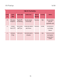
TABLE OF CONTENTS
Abstract
1
1.0 Project Overview and Block Diagram
1
2.0 Team Success Criteria and Fulfillment
4
3.0 Constraint Analysis and Component Selection
5
4.0 Patent Liability Analysis
14
5.0 Reliability and Safety Analysis
20
6.0 Ethical and Environmental Impact Analysis
25
7.0 Packaging Design Considerations
29
8.0 Schematic Design Considerations
33
9.0 PCB Layout Design Considerations
39
10.0 Software Design Considerations
41
11.0 Version 2 Changes
49
12.0 Summary and Conclusions
50
13.0 References
51
Appendix A: Individual Contributions
A.1
Appendix B: Packaging
B.1
Appendix C: Schematic
C.1
Appendix D: PCB Layout Top and Bottom Copper
D.1
Appendix E: Parts List Spreadsheet
E.1
Appendix F: Software Listing
F.1
Appendix G: FMECA Worksheet
G.1
-ii-
ECE 477 Final Report
Fall 2008
Abstract
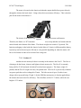
The Moto-eV concept is a full scale electric motorcycle. The electric modifications will
be retrofitted into a 1986 Honda VF500F chassis. The combustion engine and transmission will
be replaced with an electric motor and a fixed gear final drive. The Moto-eV is engineered to be
a commuting vehicle which provides a more environmentally friendly alternative to inner city
driving.
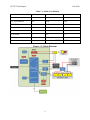
1.0 Project Overview and Block Diagram
The idea for the Moto-eV stemmed strongly from the groups mutual interest in electric
motors. All group members have taken ECE 321 and are all interested in using an electric motor
to provide some sort of personal transportation. Mike currently owns and rides a Honda VFR
motorcycle and proposed the idea of designing an electric motorcycle. The bike is powered by
either a PM brushed DC being supplied with between 48 volts. All of the hardware is fitted into
a 1986 Honda VF500F chassis and relevant user information is displayed through a LCD via
serial interface. The motorcycle is designed for short commutes to and from work or school.
Cruising speed is 35 miles per hour with effective range of 20 miles.
Mike’s focus was on choosing and integrating the hardware peripherals as well as using
his ee423 knowledge to assist Loren with motor control. He also has extensive knowledge of the
mechanical workings of motorcycles therefore he also was the lead mechanic in disassembly and
maintenance. Loren targeted motor control with hardware and in software as well as designing
the layout for the PCB. Arin undertook the responsibility lead programmer; however every
member of the team will contribute in this area. Janell took charge of packaging all of our
components into the motorcycle frame. The entire team will be committed to the testing and
debugging as well as the final paint job.
1
ECE 477 Final Report
Fall 2008
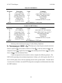
Table 1.1: Initial Cost Estimate
Part
Quantity
Price
Cost
PM Brushed DC Motor
1
$500
$500
12V SLA Batteries
4-6
$100
$600
VF500F Chassis
1
$100
$100
Metal and Fasteners
N/A
$150
$150
Sprockets
2
$75
$150
LCD Screen
1
$75
$75
Tilt Sensor
1
$15
$15
TOTAL $1,590
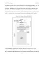
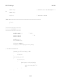
Figure 1.1: Block Diagram
2
ECE 477 Final Report
Fall 2008
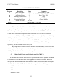
Table 1.2: Division of Labor
Design Component Homework
4-Packaging Design and Specs
5-Hardware Narrative and Prelim Schematic
6-PCB Narrative and Prelim Layout
9-Software Design Narrative
Professional Component Homework
3-Design Constraint Analysis/Parts List
10-Patent Liability Analysis
11-Reliability and Safety Analysis
12-Social/Political/Environmental Analysis
Janell
Mike
Loren
Arin
3
Mike
Arin
Loren
Janell
ECE 477 Final Report
Fall 2008
2.0 Team Success Criteria and Fulfillment
1. An ability to control an electric motor from throttle input.
2. An ability to monitor battery levels and shut down at a specified level of charge.
3. An ability to provide user selectable ride modes.
4. An ability to use a tilt sensor to monitor lean angles.
5. An ability to display pertinent data to rider using a LCD.
All of the Project-Specific Success Criteria (PSSC) were fulfilled, with some being
more difficult than others. PSSC-5 was the first to be completed. This proved useful because it
provided a means to debug all other issues with software by displaying values and registers to the
LCD.
PSSC-4 was the next to be checked off the list. This was the next logical step because
the inclinometer chip was already on the PCB and its values could be displayed onto the LCD to
ensure proper depiction of lean angle.
PSSC-1 was then completed. This was a large milestone in the project and allowed
the team its first chance to take the motorcycle out for a ride. In the end, voltage control via
PWM was utilized for this PSSC. This was the most difficult PSSC to complete due to our lack
of experience in implementing a real world drive system and issues with our current monitoring
circuit. Multiple iterations of the final drive system where designed and tested before the final 2
quadrant drive with bootstrap circuit was implemented.
PSSC-2 was the second to last to be completed. The ability to display values to the
LCD made this PSSC rather easy. The most difficult part of this PSSC was tuning in each
individual differential amplifier to display the correct voltage to the LCD.
The final PSSC to be completed was PSSC-3. This dampens the throttle input and
limits the maximum speed of the bike to allow for a novice rider to feel comfortable and safe
while riding.
4
ECE 477 Final Report
Fall 2008
3.0 Constraint Analysis and Component Selection
3.1
Introduction
The Moto-eV concept is a full scale electric motorcycle. The Moto-eV is engineered to
be a commuting vehicle and thus will be equipped for a modest range of 25 miles with a top
speed around 35 mph. The main design constraints stem from the size and weight of the 1986
Honda VF500F chassis. The combustion engine and transmission will be replaced with a
brushed PM DC motor and a fixed gear final drive.
3.2
Design Constraint Analysis
Given the target consumer of the Moto-eV is the short distance commuter, the main
constraints are focused on obtaining a certain top speed and run time. This will require a balance
of power and weight in the batteries and the motor. Also an adequately powerful motor and a
sufficient number of batteries, each with an ample amount of stored energy will be required. All
of this hardware will have to be light to reach the target performance. Interfacing with such large
power components will be extremely challenging. Some parts will be required to handle
extremely large amounts of current while maintaining long term reliability.
Interfacing with the rider via an LCD screen, throttle control, & brake control is also very
important. The Moto-eV must be safe for anyone with a moderate background of motorcycle
experience to pick up and ride. Battery level, bike side-to-side lean angle, and ride mode and
throttle data will need to be displayed for the rider to monitor the bikes conditions.
3.2.1
Computation Requirements
The primary purpose for the microcontroller will be motor control. This will be
implemented through current control. By monitoring and controlling the current feed it is easy to
prevent the motor from attempting to draw excessive amounts of current. This protects the
batteries, the switching circuit, the associated linkages, and the motor itself. The motor control
algorithm will monitor the requested throttle input and the real time current draw. This data will
be run through the software, which then will subsequently cycle two discrete digital output pins
that drive the two quadrant chopper. By applying this method of control, the system will operate
within current limits imposed by the batteries, IGBT, and motor specifications. This project
5
ECE 477 Final Report
Fall 2008
requires a very fast ATD sampling frequency to monitor the current draw across the shunt
resistor. The current algorithm will require very accurate monitoring of the current draw at a
high frequency. This is due to the speed at which the current will be increasing during times of
high load torques and low speeds.
As a backup method of motor control a voltage control method could be implemented.
It is important to make a microcontroller selection where this control option will be available in
the future. This contingency plan requires a high speed 10-bit PWM output, which will be
considered during microprocessor selection. Other uses of the microcontroller will be to
monitor & display lean angles, battery level, ride mode, and throttle levels.
3.2.2
Interface Requirements
Starting with the main motor control function the microcontroller will have to have
PWM functionality to implement voltage control. The motor driving signal will be optically
isolated and will connect to the switching circuitry through a gate driver. A serial
communication interface will be needed to communicate with the Crystalfontz LCD. Finally, it
is important to have a reasonable number (excess of 6) of general digital I/O pins to control
things such as the ride mode and LCD backlight.
Input number one will be from the current monitoring circuitry. This ATD input is
essential for the motor control algorithm. Two additional ATD inputs will be used for the 0-5kΩ
potentiometer throttle and the tilt sensor intended to monitor lean angles. Battery monitoring
circuitry will interface via an ATD input. Ride mode selection, LCD display page selection, and
LCD backlight control will each use digital input pins.
3.2.3
On-Chip Peripheral Requirements
The input – output (I/O) requirements in the previous section dictate the use of a micro with at
least five 10-bit analog to digital (ATD) inputs, three digital inputs, one channel of 10-bit PWM,
and SCI/UART functionality. Additional general I/O pins will be required for the possibility of
future peripherals.
6
ECE 477 Final Report
3.2.4
Fall 2008
Off-Chip Peripheral Requirements
The off chip peripherals that are interfaced with the microprocessor are the built in
serial communication chip on the LCD, the single axis inclinometer chip, and the gate driver
chip.
3.2.5
Power Constraints
The Moto-eV is powered from around 72Ah of battery power. Despite this large well
of energy, the drive circuitry must remain efficient in order to leave as much power as possible
available to the motor. A 5V supply voltage will provide an ample ATD resolution while not
consuming too much power. The abilities of the switching circuit will be dictated by the motor’s
power requirements. A robust switching circuit using an insulated gate bipolar transistor (IGBT)
is required for this application. To dissipate the heat generated from switching, a long heatsink
and fan is mounted below the IGBT [30]. The switching circuit and batteries will need to be able
to supply short burst of high currents up to 200 amps (with capacitor assistance). The batteries
also must provide at least 48V of power, while being rechargeable, light, and compact.
3.2.6
Packaging Constraints
The main packaging constraints were the size of the motorcycle frame. There is plenty
of room inside the tank for the large circuit board, switching circuitry, LCD, and associated
hardware. However, the batteries and motor are more restricted. The motor can only be
mounted directly in front of the swing-arm, and it should not have a depth that is wider than the
bike’s frame. The batteries are mounted inside of a ―battery cage‖. This cage is mounted in
front of the motor and behind the front wheel in whatever space is left inside the frame once the
motor is mounted. The cage is also removable in order to allow access to the individual
batteries. The dimensions of the batteries are compact, while still providing a respectable
amount of power.
3.2.7
Cost Constraints
Cost constraints are $305 per team member, for a total of $1,219.58 dollars. This is out
of pocket money and does not consider any donations made. The team acquired a LCD module
from Crystalfontz, a potentiometer throttle from Magura, 12V sealed lead acid batteries from
7
ECE 477 Final Report
Fall 2008
NPC Robotics, connectors from Molex, and fuses, fuse block, and master switch from Blue Sea.
The cost to the team was $100 for the rolling chassis and $350 for the motor, plus additional
hardware costs.
3.3
Component Selection Rationale
Chassis
The donor chassis being used for this project is a 1986 Honda VF500F. This was
chosen for its small size, frame design, cost, and ease of acquisition. The chassis was purchased
for $100 and required little maintenance to get it rolling. This is a double cradle frame, which
will be advantageous when mounting the motor and batteries. The negatives of this frame are its
weight and size. The frame is made of steel instead of the lighter alternative of aluminum, and
since the original motor was a 500cc v-four, the space that remained to install the batteries after
placing the motor was limited.
Microcontroller
When researching the different appropriate microcontrollers available for this project
it was clear from the beginning that the PIC line was more appropriate than the offerings from
Freescale. Below is an outline of the two PIC micros that the team was deciding between.
8
ECE 477 Final Report
Fall 2008
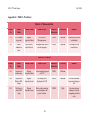
Table 3.1: Microcontrollers Under Consideration
Features
PIC18F4431 [2]
dsPIC30F3011 [3]
Peak Operating Frequency
40 MHz (10MIPS)
30 MIPS
Program Memory (Bytes)
16384
24000
I/O Ports
five 8-bit bidirectional ports
20 pins
Capture/Compare PWM modules 2
4
PWM
8 channels
6 channels
14-bit resolution
14-bit resolution
Complement mode
Complement mode
Quadrature Encoder Interface
YES
YES
ATD
10-bit High Speed (200ksps)
10-bit High Speed (1Msps)
9 input channels
9 channels
2 comparators for 2 cannel
4 S/H inputs for
simultaneous reads
simultaneous reads
Synchronous Serial Port (SSP)
SPI
EUSART
I2C
RS-232
UART
Operating Voltage (V)
5.0
5.0
Instruction Set Size
75
83
Pin Count
40
40/44
Internal Oscillator
YES
YES
Serial Communication
These two chips are very similar and both would have most likely met the project
needs. When deciding which chip to choose, the exact frequency at which the current needed to
be monitored was not known. This frequency would have been dependent on the motor, and the
team needed to get more concrete data on the motor. However, it was unlikely that a sampling
frequency greater than 200ksps was going to be required. Therefore, the team decided to use the
PIC18F4431. This processor offered all of the peripherals required and also provided enough
extra pins for any design expansions that took place.
9
ECE 477 Final Report
Fall 2008
Inclinometer
The first contender in the inclinometer selection was the Rieker H4 [4]. This
inclinometer is designed for rugged applications on cranes, agricultural equipment, and other
industrial applications. It offers a range of +/-70 degrees and outputs an analog voltage of 0-5V.
The only drawback was the cost, which is unknown, but anticipated to be in excess of $100.
The other sensor option was the VTI single axis SCA61T-FA1H1G (digikey part
#551-1005-1-ND) [5]. This small surface mount device has a measuring range of +/-90 degrees
and includes internal temperature measurements and compensations. It operates on 5V and
outputs data via an analog signal from 0-5V or SPI. Another plus to this option was that they
only cost around $40. This was the team’s best option given the constraints of operating voltage,
cost, and output options.
Batteries
There were several design constraints associated with the batteries, but the most
important was obviously voltage level. The motor must operate between 48V and 72V. To
obtain this level, the team used four 12V SLA batteries in series. It was possible to implement
more, but due to budgetary reasons it was not considered. The second constraint on the batteries
was the amount of energy they can store. With a motor that is capable of drawing over 200A in
bursts, the team needed plenty of battery capacity. This capacity was a compromise with the
third constraint, which was physical size. The frame had limited space, and measured only 13‖
wide. Also, the batteries needed to be maintenance free, rechargeable, light, and most
importantly cheap.
The website batteryspace.com offered the team a discount, and their LA-12V26Ah
model is particularly appealing. The main motivation to use this particular model is its price
point. There are other more expensive models which would offer a greater riding range, but they
are out of reach due to the team’s budget. At $50 dollars apiece the LA model offers a nice
balance. The 26Ah capacity will give a total 104Ah of power. This is obviously a compromise
on range, but should offer an increase in performance. Each battery weighs 19.4lb., which will
give a total battery weight of a mere 77.6lbs. Their 4.92‖ x 6.54‖ x 6.89‖ form factor is
extremely small, and will offer a large variety of mounting options in the bike’s frame. These
10
ECE 477 Final Report
Fall 2008
batteries are sealed lead acid and are not necessarily the ideal choice for this application. There
are several other battery chemistries which would offer better power to weight ratios. However
no technologies can beat the price of SLA batteries, despite their high weight [6].
The team also considered using 4 Panasonic LC-X1228P SLA batteries [7]. Each
battery can provide 28Ah and weighs 24.34lbs, for a total of 112Ah of power weighing 97lbs.
These batteries have a nice small size at 6.49‖ x 4.92‖ x 7.07‖ which would have been easy to
mount in the bike’s frame. The cost of these batteries was also very competitive at a mere $45 a
piece, ringing in at a total of $180. These batteries were less expensive, offered a slightly higher
capacity, but each weighed 4.94lbs more than the LA-12V26Ah. The extra 19.76lbs would have
been worth the higher quality brand name Panasonic batteries and the extra 8Ah of capacity.
Ultimately cost won out over the other criteria of weight and capacity. NPC Robotics
sponsored the team with four 12V sealed lead acid batteries with a 350A max current draw (for
10 seconds), 100A continuous current draw, and 18Ah of battery life. The dimensions of the
batteries are 8‖ x 6.5‖ x 3.5‖ and weighed in at 18.8 pounds each.
Motor
Originally this project was going to implement a brushless DC motor [8]. These
motors would be the best for this project because they offer high efficiency and zero
maintenance. Due to complexity of control, limited available motor options, and cost, the team
has decided to use a brushed PM DC motor. The rest of the system is designed around the motor
choice so the only motor constraints are efficiency, weight, operating voltage, and cost.
The best motor for this project is the Lynch/Lemco LEM-200-D127 [9]. This brilliant
motor can operate between 48 and 72 volts. It offers a rated power of 12.56kW (16.84 electric
hp at 72V) and a rated continuous current pull of 200A. At 48V the motor should output 8.55kW
(11.46 electric hp) continuously and 33.3 N*m of torque. These motors can also achieve an
amazing peak efficiency of 90%. Another benefit to this motor is its weight of only 25lbs.
Compared to a series wound brushed DC motor the team was considering, this is about twice the
power at half the weight. The one major downside to using a Lemco, is its very high cost. These
advanced motors cost over $900 shipped to the US. This price is after a discount offered to the
team by the company owner, as well as the exchange rate (motors are made in the UK).
Unfortunately this motor will be out of reach due to the extremely high price.
11
ECE 477 Final Report
Fall 2008
Another motor that was considered was the Advanced DC A89-4001 series wound
brushed DC motor. The team was offered a used one for $350 plus shipping. This motor has a
continuous output of 6hp and a peak of 27hp. A downside is that it weighs 50lbs, which is twice
that of the Lemco. This weight also corresponds to size, with the A89 being over 10.4‖ long
compared to the Lemco’s depth of 170.2mm (6.7‖). It was important to try to keep the weight of
each component to a minimum. Once everything is in the chassis the weight of the bike will
directly correspond to performance and range. Another downfall of this motor was the lack of
support. It was difficult to find much information on this motor or any previous examples of
electric vehicle implementation. Seeing as how the motor was used, the team also didn’t know
the condition of the brushes or any of the other mechanics. Yet another pitfall for the A89 is its
lack of efficiency. The Lemco is the leader in efficiency as far as brushed DC motors go.
In the end the motor choice was the Mars ME0709 PM brushed DC motor [10]. This
motor weighs in at 36lbs and a cost of $500. While the motor is twice the depth of the Lemco
and heavier, due to its lower price it is the winner. It can operate between 48V and 72V, with a
continuous current draw of 114A. The motor provides approximately 7.03kW of continuous
power at 72V. Running at 48V this number will be slightly reduced, but is still more than
enough to power a motorcycle.
LCD
The team used a Crystalfontz CFA634-YFB-KS [11]. This is a 20x4 positive screen
that has a backlight and a serial interface. The team chose this character based display for its
ease of implementation. A graphical display was an option but due to the scope of the project, it
was decided to be too ambitious. This character display offers the screen real estate required for
all of the information the rider will need, and will be very simple to interface with. A large
design constraint was for the LCD to have a positive display so that the rider would be able to
view it in direct sunlight.
Switching Technology
Darlington BJT, Power MOSFET, IGBT, & MCT were all different technologies
available for switching the motor. The team decided to use an IGBT module based on its low
12
ECE 477 Final Report
Fall 2008
gate current and low collector-emitter resistance. A separate IGBT module is beneficial in this
application due to the power which it must switch and the temperatures that the transistors will
reach during peak operation. The module architecture being used prevents excessively large
PCB traces, and in the event that it is destroyed, it will not destroy any PCB boards. When
switching 80V or less, 75% to 80% of the time power MOSFET’s are used. However the high
current and the time constraints of this application dictate the use of a sealed module and IGBT
technology.
Fairchild had graciously decided to sponsor the team by providing the half bridge as well
as the optical isolator/gate driver chip. The FMG2G150US60E IGBT half bridge can handle up
to 600V and 150A continuous across the collector and emitter [12]. This worked perfectly for
the power needs of the Mars motor.
3.4
Summary
The Moto-eV project uses a 1986 Honda VF500F chassis, powered by a Mars Brushed
PM DC motor. This motor works well for this project due to its weight and power output. The
motor runs off of 48V provided from four 12V SLA batteries in series. While these batteries are
heavier than alternate options, they offer the best price to performance, weight, & capacity ratio.
System control is implemented with a PIC18F4431. This micro provides the necessary high
speed ATD, PWM, and general I/O pins. A current control algorithm is used to switch an
external IGBT module which in turn will power the motor. Relevant user information is
provided on a character based 20x4 Crystalfontz LCD. This screen is easily interfaced with
using serial communication and offers the screen real estate required for the data. This data
consists of battery charge, current draw, throttle demand, & lean angle values. The lean angle
will be provided by a VTI SCA61T single axis inclinometer, a small surface mount chips which
provides +/-90 degrees range of measurement.
13
ECE 477 Final Report
Fall 2008
4.0 Patent Liability Analysis
4.1
Introduction
The Moto-eV is an electric motorcycle which is powered by sealed lead acid batteries and
a DC brushed permanent magnet motor. The motorcycle is designed primarily for city driving
and will serve as a stylish alternative for gas combustion vehicles. The motorcycle will offer a
number of features aside from being a transportation vehicle: an inclinometer will measure the
lean angle of the rider; a Ride Mode option which will set a maximum speed so that licensing
and age restrictions will not apply to the bike in certain states; and an LCD panel will display the
amount of battery power left to power the bike, the tilt angle of the user, the throttle demand, and
the current ride mode.
Moto-eV seems like an ideal candidate for patent infringement, since the motorcycle has
been in existence for so long, and patented extensively. When researching motorcycle, scooter,
and bicycle devices to search for any potential infringements, the existing patents must be
analyzed with respect to the main components and functions of our project. Since the Moto-eV
uses batteries to power a DC motor, and it is digitally controlled using a microcontroller and
software, there could be enough differences to show that the Moto-eV has a substantially
different function and performs in a substantially different way, in order to avoid any potential
liabilities.
4.2
Results of Patent and Product Search
Initially, research regarding patent infringement was done with respect to the functions
and methods of Moto-eV as a whole; the function being a mid range transportation device and
the method being a motorcycle driven by an electric motor which is powered by batteries. A
general view will be considered with respect to the motorcycle patent, the electric bicycle patent,
and the electric scooter patent. Then a motor control method comparison was made with respect
to the electric motor controller patent and the microprocessor motor controller having discreet
processing patent.
Motorcycle – Filing date: July 25, 1986
14
ECE 477 Final Report
Fall 2008
According to claim 1 of the motorcycle patent, a motorcycle is a device having a fairing
and a radiator. It must have a longitudinal body with a head pipe mounted to the front of the bike
extending back towards the bike. The radiator must be placed ahead of the head pipe, mounted
such that it is perpendicular to the longitudinal axis of the bike. Claim 2 then continues to
elaborate on how the instrument cluster is to be mounted above the radiator at an upward angle
toward the rider, and that a headlight is mounted on the front of the bike between the instrument
cluster and the radiator. The lighting, instrument cluster, and radiator are all to be covered by a
fairing.
The key claims for infringement would be based on the longitudinal shape and
arrangement of the instrument panels and headlights. Although, much of the motorcycle patent
was based around the arrangement of the radiator on the chassis, showing promise of substantial
differences in the way Moto-eV performs with respect to a motorcycle. Since the DC brushed
motor used to propel Moto-eV does not need to be water cooled, it will not require a radiator.
The other key points in the motorcycle patent were found in claim 3. These points
revolved around the use of fairing to enclose and protect the devices on the motorcycle. But, the
details of the fairing design are based around the radiator placement on the chassis in
coordination with the instrument cluster and headlights. Once again, the lack of a radiator has
shown substantial differences between the patented motorcycle and the Moto-eV.
Electric Scooter – Filing date: January 31, 1996
Claim 1 of the electric scooter patent explains that an electric scooter is an electrically
powered device that has a front and rear wheel connected by a tube like structure. The connector
between the front and rear wheel must also lie below the center of the wheels, parallel to the
ground, providing the place where the rider is to stand. The electric motor is mounted on the rear
wheel of the scooter which is powered by batteries mounted below the chassis of the scooter.
The primary purpose of the device is for powered travelling over the ground. Claim 2 simply
continued to dive into greater details about the same categories.
The motive for patent infringement would be the use of batteries mounted on the
chassis to power the electric motor and propel the device via the rear wheel. The Moto-eV is
extremely similar in that perspective, since there are batteries mounted within the chassis and the
motorcycle is indirectly propelled forward by the rear wheel.
15
ECE 477 Final Report
Fall 2008
Electric Bicycle – Filling date: March 26, 1998
According to claim 1 of the electric bicycle patent, an electric bicycle is technically a
bicycle frame with a high performance lightweight engine mounted onto it. The front wheel
contains the steering mechanism and the rear wheel must have a hub to accommodate multiple
gears. The motor is to be powered in conjunction with a variable V-belt drive, capable of
managing a centrifugal slip clutch so that the bicycle can utilize multiple gears. The front wheel
also contains a regenerative system to charge the battery during use of the bicycle. Claim 2
pertains to the final primary function of the patented electric bicycle. It is a mechanically
actuated power control switch to provide a motor starter power level, along with two other power
levels during use of the bike.
Electric Motor Controller – Filing date: November 11, 1986
Claim 1 states that the electric motor controller patent applies to a system that has a
current controlled motor. The speed of the motor is controlled with the use of an error signal,
which is based on the difference between the current speed of the motor and a preselected
desired motor speed. One set of terminals are to be connected parallel to the input terminals to
the controller and another set are connected in series to the input terminals to the controller. By
using a pulse train at a frequency much higher than the mechanical resonant frequency, the error
signal modulates the speed of the motor by changing the duty cycle of the pulse train. This seems
to be extremely similar to the use of a PWM system to set the motor output to specifically preset
duty cycles.
Microprocessor Motor Controller Having Discreet Processing – Filing date: Jan 30, 1990
This patent is worded in a manner that makes it sound like it is used for large scale,
multiple device motor control mechanisms. According to claim 1, the motor control is
accomplished using a microprocessor that uses its outputs to signal outputting power and uses its
inputs to read a variety of sensors providing feedback information to help control the motor
apparatus. The second main point in this patent essentially summarizes the principle of an
interrupt service routine. There are different motor control tasks accomplished at different
frequencies based on timers which define intervals in the microprocessor. The remainder of the
16
ECE 477 Final Report
Fall 2008
patent goes into great detail about the types of sensors being used for determining EMF,
calculating speeds and managing communication devices.
4.3
Analysis of Patent Liability
Motorcycle Patent
The motorcycle patent is a highly mechanical system, distinguished by its design
around the radiator. By introducing the presence of a microcontroller and controls that are
digitally analyzed using software, the substantial differences between Moto-eV and the patented
motorcycle seem great enough to avoid literal infringement with the help of a good lawyer. The
fact that Moto-eV is meant for smaller distances and lower speeds than that which a fuel
combustion engine is capable of, could help to push the substantially different methods and
functions of Moto-eV with respect to the doctrine of equivalents.
Electric Scooter
Factors supporting the substantially different methods and functions of Moto-eV from
an electric scooter would be based on the type of travelling and way that travelling is performed.
For example, a scooter could be used for inner city travelling, but could it be used to travel to
work from home, or any other particularly long distances? Since Moto-eV has a sitting user
position, a 48 volt power source, and most probably a higher top speed, it would be suitable for
purposes beyond the scope of the electric scooter. The fact that the motor is not literally attached
to the rear wheel could also be twisted by the lawyer to show that it functions substantially
differently from the motor mounted onto the rear wheel of an electric scooter. Some licensing
may be necessary to legally manage production of the Moto-eV prototype even after considering
any substantial differences with the point of view of the doctrine of equivalents, but literal
infringement should not be an issue.
Electric Bicycle
Most of the defining characteristics of the electric bicycle patent do not interfere with
the key aspects of Moto-eV. The part of the electric bicycle that would give the most incentive to
file a case of patent infringement would be the power control system. The system on the electric
bicycle is controlled using a mechanically actuated switch, though, which is substantially
17
ECE 477 Final Report
Fall 2008
different than having a digitally controlled power switch. Most other aspects of the bike can be
dodged easily enough, since Moto-eV will be a single gear motorcycle with no regenerative
battery charging system, removing any conflicts with a clutch based motor drive or battery
charging methods.
Electric Motor Controller
This patent will fortunately play no role in patent infringement since it was filed over
twenty years ago.
Microprocessor Motor Controller Having Discreet Processing
This patent is worded in a manner that makes it sound like it is used for large scale,
multiple device motor control mechanisms. The motor control is accomplished using a
microprocessor that uses its outputs to signal outputting power and uses its inputs to read a
variety of sensors providing feedback information to help control the motor apparatus. The
second main point in this patent essentially summarizes the principle of an interrupt service
routine. There are different motor control tasks accomplished at different frequencies based on
timers which define intervals in the microprocessor. The remainder of the patent goes into great
detail about the types of sensors being used for determining EMF, calculating speeds and
managing communication devices.
There are a number of similarities between the function and way that Moto-eV
accomplishes motor control and the way the Microprocessor Motor Controller Having Discreet
Processing does things. The use of different intervals of time to accomplish tasks at different
intervals would probably be extrapolated for the purpose of maintaining a sense of priority,
although it wasn’t specifically documented in that fashion. The wording was quite ingenious in
this patent, because it essentially makes any motor controller that uses interrupt service routines
viable for infringement. This is a definitive candidate for patent infringement under the doctrine
of equivalents for having substantially the same function in a substantially same method.
4.4
Action Recommended
For the first three of the previously mentioned patents, there does not seem to be any
highly intimidating potential for infringement. The motorcycle and electric bicycle patents both
18
ECE 477 Final Report
Fall 2008
used exclusively mechanical systems. This is a huge factor of persuasion under the doctrine of
equivalents in support of Moto-eV. When comparing the capabilities and functions of a digital
system to those of a mechanical system, vast differences can be found in how Moto-eV functions
and what its purposes are. The main gist of the substantially different functions lies in the
exclusive purpose of travelling moderate distances, like the kind of travelling that takes place
regularly in high traffic, metropolis areas. It would be unlikely that the motorcycle or electric
scooter could find the legal prowess to show that Moto-eV is guilty of patent infringement. The
electric bicycle is more similar to Moto-eV in its purpose than the motorcycle or scooter, but
once again the mechanical systems of the clutch and gear switching components have caused
great differences between Moto-eV and the electric bicycle.
Thus, the action recommended would be to highly emphasize the differences between
mechanical systems in the current patents and the digital systems being implemented in MotoeV. In the case that patent infringement does become a real issue and digital systems are not
capable of showing their substantial differences in how the devices work. The functions of MotoeV should be brought up to explain that the purpose of Moto-eV may overlap with that of a
motorcycle, scooter, or bicycle, but mostly entertains its own category of city travelling at
moderate distances. Ultimately, all is in vain though. The Microprocessor Motor Control Having
Discreet Processing would definitely be a case of patent infringement under the doctrine of
equivalents. Since Moto-eV doesn’t have the financial prowess to manage licensing the patent,
the only option would be to not produce the motorcycle until the patent were to expire.
4.5
Summary
In summary, the patents that most closely resemble the functions and methods of Moto-eV
are the motorcycle, electric scooter, and electric bicycle; and the patents that resemble the motor
control mechanism is the Electric Motor Controller and Microprocessor Motor Control Having
Discreet Processing. After reviewing the patents of those devices, the Microprocessor Motor
Control Having Discreet Processing would be a definitive issue with regards to patent
infringement under the doctrine of equivalents. Licensing would be the only possible option as
this point, but due to financial constraints, the only viable option is to wait for the expiration of
the patent at hand.
19
ECE 477 Final Report
Fall 2008
5.0 Reliability and Safety Analysis
5.1
Introduction
The Moto-eV is designed to be an inexpensive and environmentally friendly form of
transport for individuals living in condensed urban areas. It can transport the rider a distance of
up to 20 miles at 35 MPH on a single charge an can be recharged in under 6 hours. The MotoeV will function just as any other motorcycle will, with the expectation that it is fixed gear and
fully electrical. The main safety concern for this project is protecting the wellbeing of the rider
and the motor control system by avoiding injury and damage from falling over. The Moto-eV
can only go so far in protecting the rider from danger; ultimately it is still the rider’s
responsibility to be a safe and smart driver. A safety feature that has been implemented on the
bike is a mechanical kill switch. This physically breaks the circuit that sends power to the motor
in case there is a failure with any part of the motor control circuitry and the motor ramps up
without any user input. With this implemented, if the user does lose control over the motor
speed he can simply turn a key and shut down the motor.
To be a successful and commercial product, the Moto-eV also needs to be reliable.
The schematic has been broken down into five functional blocks, and components from each will
be analyzed individually. A few of the most critical components that will be represented in this
report include the LT 1529 Linear Voltage Regulators [34], the PIC18F4331 microcontroller [2],
the CM300DY-24H IGBT [30], and the LM2733 Boost converter [35]. The failure rate and
mean time to failure (MTTF) are included in the tables below for each of the previously
mentioned components.
5.2
Reliability Analysis
The components mentioned above have a high risk associated with them if they fail. They
have been analyzed for reliability and the results can be seen in the tables below. The LDO,
boost, IGBT’s are the components in with the highest probability of failure due to over-heating.
If the LDO failed it would cause the entire system to stop working. A failure in the boost
converter would simply cause the battery monitor to fail. A failure of the IGBT’s can in the best
scenario, simply open circuit and shut down the motor. Although it could also short and cause
20
ECE 477 Final Report
Fall 2008
the motor to ramp up out of control and risk causing serious injury to the rider. The
microcontroller is also highly critical because it is what reads the user inputs and system
feedback and determines how to drive the motor. If this component fails, then the entire system
cannot operate.
The tables that follow are a compilation of the necessary variables and calculations to
determine the number of failures per 106 hours and mean time to failure (MTTF) for each of the
previously mentioned components. Referring to the model found on page 25 of the Military
Handbook: Reliability Prediction of Electronic Equipment [36]:
and
for microcircuits and microprocessors. Therefore,
these can be used to calculator the failures/106 hours and MTTF for the microprocessor, LDO,
and boost converter. In these equations, P is the number of failures per 106 hours, C1 is the die
complexity, T is the junction temperature coefficient, C2 is the package failure rate, E is the
environmental constant, Q is the quality factor, and L is the learning factor associated with how
long the particular component has been manufactured.
Certain assumptions have been made in order to complete the following analysis. Such
as all components are operating at their respective maximum temperatures. Also, the system will
be ground mobile with commercially manufactured parts and has been in production for over two
years. The tables below are used to derive the failure rates and MTTF using these assumptions
and information taken from the component datasheets.
Table 5.1: LT 1529 Linear Voltage Regulator
Parameter
C1
πT
C2
πE
πQ
πL
λP
MTTF
Description
Die Complexity
Temperature Factor
Package Failure Rate
Environmental Factor
Quality Factor
Learning Factor
Failures/106 hours
Value
.02
58
.0016
4
10
1
11.664
Comments
Linear, MOS 101-300 transistors
Linear MOS, Max Temp of 125° C
4 pins, Nonhermetic DIP
Ground Mobile
Commercial
In Production for over 2 years
85,733.88 hours = 9.787 years
21
ECE 477 Final Report
Fall 2008
Table 5.2: PIC18F4331
Parameter
C1
πT
C2
πE
πQ
πL
λP
MTTF
Description
Die Complexity
Temperature Factor
Package Failure Rate
Environmental Factor
Quality Factor
Learning Factor
Failures/106 hours
Value
Comments
.28
16 bit, CMOS
3.1
CMOS, Max Temp of 125° C
.019
40 pins, Nonhermetic DIP
4
Ground Mobile
10
Commercial
1
In Production for over 2 years
9.44
105932.20 hours = 12.093 years
Table 5.3: LM2733 Boost
Parameter
C1
πT
C2
πE
πQ
πL
λP
MTTF
Description
Die Complexity
Temperature Factor
Package Failure Rate
Environmental Factor
Quality Factor
Learning Factor
Failures/106 hours
Value
Comments
.02
Linear MOS 101-300 transistors
58
Linear MOS, Max Temp of 125° C
.0016
4 pin Nonhermetic SMT
4
Ground Mobile
10
Commercial
1
In Production for over 2 years
11.64
85733.88 hours = 9.787 years
Referring to the model found on page 58 of the Military Handbook:
and
for high power, high frequency bipolar transistors.
In these equations,
is the number of failures/106 hours,
temperature factor,
is application factor,
factor, and
is the base failure rate,
is the matching network factor,
is the
is the quality
is the environmental factor.
Certain assumptions have been made in order to complete the following analysis. The
IGBT will be operating at its maximum temperatures. Its duty cycle will be greater than 30%, it
has a JANTX quality factor with a no matching network and is ground mobile. The table below
is used to derive the failure rate and MTTF using these assumptions and information taken from
the IGBT datasheet.
22
ECE 477 Final Report
Fall 2008
Table 5.4: CM300DY-24H IGBT
Parameter
λB
πT
πA
πM
πQ
πE
λP
MTTF
Description
Base Failure Rate
Temperature Factor
Application Factor
Matching Network Factor
Quality Factor
Environmental Factor
Failures/106 hours
Value
Comments
2.12
Power output of 750W
2.4
VS=VCE/BVCES; VCE=48V BVCES=1200V
2.2
Duty Cycle > 30%
4
None
1
JANTX
10
Ground Mobile
447.744
2233.42 hours = .255 years
These results and calculations are derived for the worst case scenario for each
component. To get these results, T is assumed to be at the maximum operating temperature
before the component burns up and no longer works. That is why the MTTF is relatively low. If
we used a more conservative temperature value to calculate MTTF for the LDO and boost
converter such as 35° C (T = 0.23), the MTTF would increase to nearly 250 years for both chips
and 230 years for the microprocessor. Along with the assumption of maximum operating
temperature, I assumed a 300 amp current draw on the IGBT. If more reasonable values were
chosen such as a temperature and current draw such as 100° C (T = 0.38) and 50 amps
respectively; the MTTF would increase to 94 years.
By using values for T and λB that are in a more reasonable range, the MTTF for these
critical components drastically increases. Based on the operation at lower temperatures, the
reliability of each of the critical components is acceptable.
5.3
Failure Mode, Effects, and Criticality Analysis (FMECA)
The schematic can be broken down into five major functional blocks. Appendix A contains
the schematics of each functional block while Appendix B contains the FMECA Worksheet
which provides information about the different failure modes, causes, effects, and criticality for
each of the functional block. The functional blocks are organized in the following manner:
A. Microcontroller
B. Sensors
C. Power
D. Motor Control
23
ECE 477 Final Report
Fall 2008
E. User Interface
Each failure is assigned a failure criticality level corresponding to its severity. The
following table explains how the levels are broken down.
Table 2.1: Criticality levels
Criticality
Failure effect
Maximum Probability
Failure that causes system instability
High
Possible damage to user and/or system
Medium
Requires replacement of minor component
Causes undesirable behavior
LCD malfunction, incorrect battery level
Low
No damage to device
5.4
p ≥ 10-6
10-6 < p < 10-9
p ≤ 10-9
Summary
The components that were analyzed are very important because failures in those particular
functional blocks have high criticality. MTTF is a good estimate of the lifetime of these
components and by operating them in a reasonable range they should be more than sufficient for
use in the Moto-eV. With regards to the FMEC analysis, the most critical failures occur in
Sections D & E which contain the motor control and user interface. Failure in any of these two
regions can cause damage to the device or the user. Precautions have been taken to prevent
such accidents but unforeseen complications can arise during operation that will have to be
corrected before the Moto-eV is ready for commercial production. Overall, Moto-eV is a safe
and reliable product.
24
ECE 477 Final Report
Fall 2008
6.0 Ethical and Environmental Impact Analysis
6.1
Introduction
The Moto-eV is a full scale electric motorcycle. The Moto-eV is engineered to be a
commuting vehicle and thus will be equipped for a modest range of 25 miles with a top speed
around 40 mph. The bike will be powered by a bank of four 12V SLA batteries connected in
series to provide 48V to the motor. The microcontroller will run off of a single, sealed, 12V
lantern battery mounted inside the tank.
Just like any other product that is going to be marketed, there are ethical and
environmental issues that need to be taken into consideration prior the release of the product.
As a mode of transportation, the main ethical concern would be the safety of the rider.
Therefore, where to place warning labels and the testing of the product in many situations was
taken into consideration. In terms of environmental issues, topics to consider are pollution and
waste that may take place during the three phases of the product’s life: manufacturing, normal
use, and recycling/disposal.
6.2
Ethical Impact Analysis
Since there are many ethical considerations that needed to be taken into account prior to
the production of the Moto-eV the Institute of Electrical and Electronics Engineers (IEEE) Code
of Ethics [18] was used as a reference. The rider’s safety is at utmost importance since the
Moto-eV will be considered a motor vehicle to be used on public streets, roads, and highways.
Thus, it is required to abide by the Federal Motor Vehicle Safety Standards (FMVSS) [19]. The
bike will need to be tested for different temperature ranges to ensure that all parts are able to
withstand the low and high temperatures that the bike may encounter. Then if there is a
temperature range in which the bike does not function well, the appropriate advisories can be
placed in the user manual. The bike is also not water proof, therefore, it will be advised to not
use the bike when it is raining or snowing. The bike should also be tested on pavement, gravel,
dirt, grass, and any other possible terrains the driver may encounter. It is considered a road
ready motorcycle, though, and the rider will be advised to not drive the bike on rough terrains.
25
ECE 477 Final Report
Fall 2008
In that case that it is necessary to take the Moto-eV off-road, the manual will instruct one to
proceed with extreme caution.
With safety being the main concern there will be labels added on specific components of
the bike, to indicate a possible danger. The most significant source of danger is the battery
cage, especially since the batteries will be in series with the capability of supplying 48 volts.
Therefore a label would be placed on the battery cage indicating the danger that could occur if
one somehow managed to get short circuited. The battery cage would also include a picture that
represents an electrical hazard and a page number for the manual in order to explain the
potential danger in greater detail. Even though the tank should not be taken off, another
warning label would be placed on the electronic mounting plate that is located under the tank
which holds the PCB, shunt resistor, and IGBT. The warnings would show a picture to
represent that some parts may be hot to the touch and represents the possibility of electrical
hazard. There is also a cord attached to the battery charger so that the bike can be plugged into
a wall outlet, which will need warning to indicate electrical hazard possibilities. The warning
would also include a page number reference to the manual to explain the potential danger in
greater detail.
Another ethical consideration is how reliable the battery monitoring system is. If for
some reason the display was indicating a battery is charged at a higher value than it actually is,
and a user gets stuck somewhere because of this, there would be a problem. Therefore
numerous tests would be preformed to ensure data values are accurate at all times of the battery
charge cycle to maintain accuracy with time.
The user manual will be the main source of communication between the manufacturer
and the customers. This will provide the user with crucial information for their safety, service
information, how to drive the Moto-eV, and troubleshooting information on any type of problem
that may arise. Due to that fact that Moto-eV is a street legal motorcycle, it would require a
license to drive, which would also be clearly stated in the manual. The manual will discuss the
possible driving environments and how the motorcycle will react in all of the situations tested
above and advise against driving on certain terrains and in specific weather conditions. The
manual will also specify how many riders are permitted at one time with respect to weight limit.
It would also advise wearing proper motorcycle gear which includes a helmet, riding jacket, and
riding pants. The warning labels will be explained in more details. With the Moto-eV
26
ECE 477 Final Report
Fall 2008
displaying the lean angle this leads to possible desire for competition in achieving a greater lean
angle, therefore the manual will indicate that the lean angle measurement is for safety and
feedback purposes and not to be used as a means of competition. Lastly, the manual will provide
contact information for Moto-eV retailers, maintenance, and information for disposal/recycling.
For additional safety, there is a kill switch that will complete cut the power to the motor.
In the case of a defect or accident resulting in the gate drive getting stuck, the motor can be
disconnected from the power source to maintain control.
6.3
Environmental Impact Analysis
Besides just ethical concerns, environmental impact also must be taken into
consideration. This can take place in any of the three stages of the life of the product:
manufacturing, normal use, and disposal/recycling. The main concern during the manufacturing
stage is the pollution that occurs during the fabrication of the printed circuit board (PCB), from
the chemicals and natural resources that are needed in the fabrication process. Therefore all the
chemicals and materials must be separated and taken care of respectively. With this taken into
consideration, Moto-eV would look into the production and waste procedures to determine a
producer.
Use of the Moto-eV is more environmentally safe than most other motorcycles, due to the
fact that the Moto-eV does not have harmful emissions. The batteries could become an issue if
they were to become damaged, for instance, if the bike was in a collision. Thus, sealed lead acid
batteries were selected to prevent of any chemicals from leaking into the environment. Also
during normal production tires will need to be changed periodically and the old ones will need
to be discarded. In order to be more environmentally safe the manually will provide
information for the recycling of the tires. [20]
At the end of the product’s life the product should be taken apart so that different
components can be disposed of or recycled as needed. The batteries should be brought to any
automotive store so that they can be recycled; this information will be in the manual. As for the
PCB and LCD there will be information in the manual so that they can be sent back to the
company where the material will be disposed of properly. For the rest of the frame, it could be
recycled either in pieces or as a whole. [21] For the disposal of the tires, users will be advised to
find proper recycling facilites.
27
ECE 477 Final Report
6.4
Fall 2008
Summary
The ethical and environmental impact of the Moto-eV has been carefully considered. The
main ethical concern is the safety of the rider, therefore, many test will be implemented prior to
the production of the bike. Also, there will be warnings located on the bike with more
information on what the labels mean and how to ride the motorcycle located in the manual.
With respect to the environmental impact, the major concern was the PCB, LCD, and the proper
disposal of the batteries.
28
ECE 477 Final Report
Fall 2008
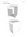
7.0 Packaging Design Considerations
7.1
Introduction
As an electric motorcycle the Moto-eV requires that batteries and motor must fit within
the frame of the motorcycle. The chassis that is used for this product is a 1986 Honda VF500F.
The main constraint is that the motor must be mounted directly in front of the swingarm. The
PCB, switching circuitry, LCD, and associated hardware fit underneath the existing tank.
7.2
Commercial Product Packaging
With the current energy crisis people are doing anything to try and limit the amount of
gas being used. Consequently, the demand for electric vehicles has increase. Some commercial
products that are similar to the Moto-eV are Enertia, Zero X as well as a few others, but they
tend to be more along the lines of a dirt bike or scooter. However, Honda and Yamaha are both
planning on coming out with an electric motorcycles within the next two years. Therefore, the
packaging methods of the products currently in the market were taken into consideration when
coming up with the packaging for the Moto-eV.
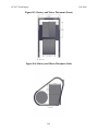
7.2.1
Product #1
The Enertia Electric Motorcycle (EEM) is a new product that is just coming into
market and being sold for $11,995 and weighs 280 pounds. The EEM can travel 35 miles per
charge with a top speed of 50 mph and a recharge time of 3 hours. As for general dimensions the
length of the EEM is 80‖ with a body width of 12.5‖ and 19.5‖ from peg to peg. The wheelbase
will be 55 inches, while the seat height is 33 inches.
Figure 1
29
ECE 477 Final Report
Fall 2008
The motor is located on the chassis such that the output shaft delivers power directly
through the chain to the back wheel. Using a direct drive maximizes efficiency. This is also the
plan for the motor of the Moto-eV .
The chassis of the EEM is engineered
Figure to
2 simply hold the motor and batteries.
Therefore, the frame is a ―H‖ beam that holds three batteries on top and three on bottom with the
motor located at the bottom of the frame. The chassis weighs in at a total of 16 pounds. The
batteries packaging is ideal with this chassis, but the Moto-eV chassis is different and the battery
layout may not be the most space efficient or even possible depending on where the motor will
have to be located in order to be in front of the swing-arm.
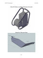
7.2.2
Product #2
Another electric motorcycle that is currently in the market is the Zero X. The Zero is
claiming to be the fastest, cleanest, and lightest electric motorcycle. The Zero X is currently
being sold for $7,450 and used for both off road and street purposes. The frame weighs 18
pounds, and the Zero X weighs in at only 140 pounds total. The Zero X is powered by a lithiumion power pack that can be recharged in 2 hours. The bike can travel up to 40 miles in one
charge with a top speed being 55 mph. Like the EEM the motor power is directly applied from
the chain to the back wheel for efficiency. The wheelbase will be 55.75 inches, while the seat
height is 35.5 inches.
30
ECE 477 Final Report
Fall 2008
With the lithium-ion power pack the frame is more compact that the Moto-eV layout.
This allows for a much smaller and light weight bike, but also strays away from a motorcycle
and towards a dirt bike.
7.3
Project Packaging Specifications
Packaging of the Moto-eV revolves around the 1986 Honda VF500F chassis. The motor
is placed in the frame directly in front of the swingarm. The battery pack is placed directly in
front of the motor. The battery pack consist of four 12 V batteries in a cage that uses the existing
frame mounts.
The old tank was cut open and used for as a protective shell for the electronics. The
PCB board, which is estimated to be 72mm by 83mm, and IGBT, 93mm by 35mm by 30mm, is
placed underneath the tank. The micro battery is mounted right next to the rear shock where the
stock motorcycle originally mounted its 12V battery. The LCD is mounted on the top of the tank.
The rider merely needs to look directly down to view critical data.
7.4
PCB Footprint Layout
The microcontroller, a PIC18F4431 is used in a 40 pin DIP package. The inclinometer
SCA61T chip is 10.48mm by 11.31mm. While the driver, an IR2184 chip, is 9.9mm by
10.30mm. This leads to a PCB board that is approximately 72mm by 83mm.
7.5
Summary
The Moto-eV’s main packaging constraints come from the fact we are using a prebuilt
chassis. Every component must fit within this existing frame. The main constraints are the
location of the motor and batteries. After looking at other commercial products packaging, the
31
ECE 477 Final Report
Fall 2008
initial plan of mounting the motor right in front of the singarm was confirmed. The battery pack
was designed to fit within the frame and we are utilizing the old tank to protect our sensitive
electronics.
32
ECE 477 Final Report
Fall 2008
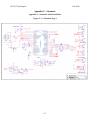
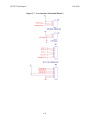
8.0 Schematic Design Considerations
8.1
Introduction
The Moto-eV concept is a full scale electric motorcycle. The Moto-eV is engineered to
be a commuting vehicle and thus will be equipped for a modest range of 25 miles with a top
speed around 35 mph. The design requires precise sensor input to the microcontroller as well as
medium to high frequency switching motor drive output. We are using seven analog inputs to the
microcontroller and this data cannot be corrupted from the noise generated by the switching
circuitry and the motor.
8.2
Theory of Operation
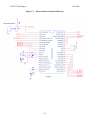
Microcontroller
The PIC18F4431 microcontroller interfaces with all of the major components on the
bike [2]. The main function of this component is to collect relevant sensor and user input data,
then process this data to modify the motor control and user display. The microcontroller will
capture inputs from the throttle, an inclinometer, and a battery monitoring circuit. The throttle
information is used for motor control, while the battery monitoring and inclinometer will be used
for the user display.
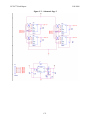
Power Supply
The Moto-eV will have two completely separate power systems. The main 12V
system will run off of a single, sealed, 12V battery mounted inside the tank. The components on
the pcb that will run at the full 12V are the gate driver, the heatsink fan, and the differential
amplifiers. The gate driver will take the logic level 0 to 5V from the micro and then optically
isolate and amplify that signal. The 12V micro battery will be stepped down to 5V through a
linear regulator to power the other circuitry on the pcb [34]. While a linear regulator is not the
most efficient means of converting a DC signal to a lower DC signal, this method was chosen for
its simplicity. When compared to the power being used by the rest of the system in the bike, the
small amount of power lost in this component is of little concern. This 5V will power the
microcontroller, LCD, inclinometer, & system lighting.
33
ECE 477 Final Report
Fall 2008
The other power system used inside the bike will be completely dedicated to the
motors. A bank of four 12V SLA batteries connected in series will be used to provide 48V to the
motor. This system will need to be separate from the microcontroller 12V system, but issues will
arise from having two supplies and two separate grounds. This issue was solved by using a
common chassis ground. It is necessary to isolate the micro system because of the huge amounts
of power the motor requires. The motor can pull 114A continuously and peak draw can exceed
300A. We used 4 gauge wire to connect the batteries, IGBT, & motor. This large diameter wire
is necessary to handle the large amount of current our drive system uses.
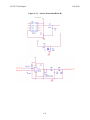
Sensors & Inputs
A single axis inclinometer is used to monitor bike lean angles [25]. This chip is
oriented on the pcb (at a slight anlge to the horizon, with pin one facing the front left of the bike)
such that it will record side-to-side changes in angle. The inclinometer has an internal
temperature sensor and it adjust its output in real time using the collected temperature data. This
is very beneficial because inclinometers are in general very sensitive to temperature fluctuations.
This sensor will interface to the micro via an ATD pin and then calculations in software provide
accurate angle measurements.
Micro battery monitoring is implemented using a simple voltage divider connected
directly to the battery and input through an ATD pin. It will be important to use very high value
resistors as to not draw too much current away from powering the motor. While there are more
elegant and efficient means of implementing a charge monitoring circuit, this alternative
provides the simplest solution. Also since the micro battery is of the lead acid chemistry, the
battery level drop off should be quite linear. This linearity provides an accurate measurement
using a voltage divider. However the main 48V battery bank is monitored by differential
amplifiers. Each of the four 12V SLA batteries is read and displayed via the LCD. This gives
the user early warning if one of the batteries is starting to go bad.
The main motor control input is the throttle. The team has obtained sponsorship of a
0-5k potentiometer throttle from Magura. This is a complete unit which can mount directly in
place of a normal mechanical motorcycle throttle. It will interface with the micro controller via
an ATD pin. 100% open throttle will correspond to about 0Ω of resistance. This input will then
34
ECE 477 Final Report
Fall 2008
be directly related to current. The torque equation for a Brushed PM DC motor is Te=kvia. This
means that the electromagnetic torque produced by the motor is directly related to the armature
current by a motor constant kv. This is the advantage of implementing current control, and this
was how the throttle data would have been interpreted in software. However due to time
constraints and other project issues a more simple voltage control scheme was used via PWM.
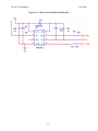
Motor Controller
The motor will be controlled using a PWM signal from the micro. The original plan
of current control was abandoned due to time constraints. However if it were to be implemented
in the future a pin will be toggled on and off based on the control algorithm. The frequency of
this signal is not a discrete number, but will vary depending on the load torque and throttle input.
Based on the throttle input, the necessary current can be calculated. This requested current
would be given a certain hysteresis. The actual current will then alternated in between the top
and bottom hysteresis. It is anticipated that the motor will switch between 4kHz and 10kHz.
However using a simple PWM signal ignores the current the motor is pulling and simply alters
the applied voltage. The signal is then be fed to an optical isolator and gate driver [26]. This
chip will protect the micro, while amplifying the control signal to 12V, the level required by the
IGBT module [30]. Originally the team anticipated using a full bridge (4 switches) to control the
motor, but a motorcycle does not need to run in reverse. Next a half bridge was considered (2
switches), but this was decided against because regenerative braking will not be implemented. A
single switch will lower cost and still provide ample performance. Half bridge IGBT modules
rated at 300A are used due to their cost and because they are much more common than single
switches. However only the top switch is controlled, while the bottom switch is grounded.
LCD
To interface with the rider a large 20x4 backlit LCD is being used [31]. This provides
data such as battery level, lean angle, and throttle position. The LCD interfaces with the
microcontroller through a USART connection. The LCD module has built in serial
communication chips, so it was relatively simple to interface with using the built in USART
functions.
35
ECE 477 Final Report
8.3
Fall 2008
Hardware Design Narrative
Once it was clear what sort of pin each part of the circuit needed, the microcontroller pins
were all chosen based upon their physical location. Due to noise, it was attempted to keep all of
the analog inputs far away from the high frequency switching ports.
The ATD module is used extensively for reading all of the system’s sensors and inputs.
The 0-5kΩ potentiometer throttle is monitored through input on pin RA0. The inclinometer
outputs 0-5V based on angle levels and interfaces through RA3. The micro battery monitoring
voltage divider inputs on RA8. This circuit was designed to output 4.36V given a full 12V of
battery charge. The resistor values were chosen using commonly available parts as well as
allowing for some headroom for slightly higher than 12V battery levels. The 4 individual 12
SLA batteries input on pins RA5, RE0, RE1, and RE2. The current monitoring circuit would of
interfaced through RA4.
The PWM module is used for our main motor drive. The motor is driven at a frequency
of 7.8kHz. This frequency is audible, but when riding the bike there are several, more prevalent,
noises.
Several general I/O pins are used as well. A LCD display selector switch and a ride
mode selector are interfaced via RC4 and RD3 respectively. The motor control signal will
output on pin RB1. This pin was carefully selected to be both a digital I/O and a PWM capable
pin. This leaves the team with a contingency plan of running the motor via PWM should the
current control scheme fail. Where in the end, we did abandon current control and implement a
voltage control. Lastly pin TX will be used to output LCD data.
36
ECE 477 Final Report
Fall 2008
Table 8.1: Pinout and Signal Table
Signal
Pin Title
Pin Number
Reset
!MCLR
1
Throttle In
AN0
2
Shunt
AN2
4
Inclinometer In
AN3
5
Battery 1,2,3,4 & micro-batt
AN4, AN5, AN6, AN7, AN8
6,7,8,9,10
Ride Mode Select In
RC4
23
Power +5V
Vdd
11
GND
Vss
12
LCD Data Out
TX
25
Motor Control Out
RB1/PWM1
34
ICSP Programming Entry Pin
PGM
38
In-Circuit Debugger & ICSP
PGC
39
PGD
40
Programming Clock Pin
In-Circuit Debugger & ICSP
Programming Data Pin
8.4
Summary
The Moto-eV circuitry has been carefully designed to provide the sensitivity required for
the analog inputs while simultaneously providing high frequency (high noise) motor drive
signals. The two power supplies are designed to provide ample current for the motors as well as
the controlling circuitry. These power supplies are regulated to stable voltage supplies. The
microcontroller’s analog inputs are filtered and amplified where necessary, while the motor
control output is optically isolated and amplified via a gate driver. The end result is a noise
resistant circuit which performs to the team’s performance expectations.
37
ECE 477 Final Report
Fall 2008
38
ECE 477 Final Report
Fall 2008
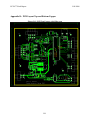
9.0 PCB Layout Design Considerations
9.1
Introduction
The Moto-eV is designed to be an inner city commuter vehicle with a range of 25 miles
and a top speed of around 35 to 40 mph. The three major components of the design are the
motor, drive circuitry and the brain board. All of these must be designed to mesh with each other
in order to create a reliable working product. The brain board will accept user inputs in the form
of a throttle and other various switches and output to the rider via a Crystalfontz LCD screen
[31]. The brain board also sets the parameters of the drive circuitry which in turn apply the
proper voltage and current to the motor.
9.2
PCB Layout Design Considerations – Overall
The Moto-eV PCB has a number of design considerations. The PCB is partitioned into
four quadrants, all contained on one board. These quadrants are power regulation, analog I/O,
digital I/O, and gate drive. This is mainly to isolate any sensitive signals from noisy high
frequency/high current signals.
First, the board requires a 12V input which will be passed through the LT1529 voltage
regulator which supplies 5V to most of the PCB components [34]. The reason such a high
supply voltage was chosen is because the gate driver requires a 12V source and this way we will
not need two separate batteries to operate the PCB. A 48V source will also be attached to the
PCB from our battery bank in order to monitor the charge level on the batteries. The 48V pack,
the ―dirty supply‖ and the 12V rail, aka the ―clean supply‖ share a common ground.
The second area is where the analog I/O is placed. This accommodates the throttle input,
shunt resistor input, inclinometer, and amplifier. Noise on either the throttle or the shunt resistor
lines can severely impact the performance of the bike. These inputs are also located close to the
micro to avoid long traces that can lead to parasitic inductances. A standard 12 mils trace is used
for this section. Special care must be taken in the placement of the inclinometer due to it only
being a single axis, and that axis must be perpendicular to the angle of incline [25].
39
ECE 477 Final Report
Fall 2008
Thirdly, the digital I/O is isolated to again avoid noise on the signal. This is not nearly as
important as the analog I/O because we can accommodate a larger variation in the digital signal
and no key control or device monitoring will be conducted on these lines.
Finally the gate driver is as far as possible from the analog I/O. This is due to the high
current draw and fast switching frequency that the gate driver must achieve [26]. These are the
main factors that contribute to EMI and because of this a ground pour underneath the IC would
be favorable. The trace leading to the output header is approximately 50 mils to accommodate
the current draw which is expected to be in the 300mA range.
There is plenty of mounting space for the board so size is not really an issue. An initial
estimates of 6x6 (inches) was chosen, and the final board dimensions measured in at 5.735‖ x
4.975‖. This provides us with enough space to isolate our sensitive components and to keep our
trace lengths short enough to avoid parasitic inductances.
9.3
PCB Layout Design Considerations – Microcontroller
The microcontroller is a PIC18F4431 and we have chosen a DIP package due to its
simple installation and port pin arrangement [2]. The micro is placed vertically in the middle of
the board to allow easy access to the port pins from each IC. The port pins for each device were
chosen to help facilitate the partitioning of the board into its four quadrants. The microcontroller
itself will not source much current so a 50 mil trace is more than adaquate. The power and
ground traces run up the side of the micro and branch out to supply power to the micro and
individual IC’s. Several bypass capacitors are placed underneath the micro to facilitate any
instantaneous power needs. No external oscillator is needed with this microcontroller since we
are not doing anything that requires very precise timing. The internal clock will be more than
accurate.
9.4
PCB Layout Design Considerations - Power Supply
The 12V source is sent through the LT1529 to produce the 5V rail. The maximum
current draw will be 2 Amps therefore the power and ground traces are 100 mils. The current is
largely dependent on how bright our LCD backlight is. The LCD backlight at full brightness,
will pull 380 mA. The 5V rail also supplies the LM2733 which boosts the voltage to 20V. This
is only to power the differential amplifiers and will not draw much current. The power traces
40
ECE 477 Final Report
Fall 2008
from the LM2733 will are 30 mils. Bulk capacitors are placed close to where the sources enter
the board and decoupling capacitors are placed under the all of the IC’s.
9.5
Summary
In conclusion, the PCB is partitioned into four quadrants with the microcontroller at the
origin. This is done to isolate sensitive signals from noisy ones and to keep all trace lengths to
the micro down to a minimum. This also reduces EMI and parasitic inductances that can cause
significant degradation in the SNR. Large traces are used for the power and ground due to the
large current draw from the gate driver and LCD backlight. Careful planning of part placement
and port usage makes the PCB layout process run much smoother and take considerably less
time.
41
ECE 477 Final Report
Fall 2008
10.0 Software Design Considerations
10.1 Introduction
The Moto-eV concept is a full scale electric motorcycle. The Moto-eV motorcycle is
engineered to be a commuting vehicle and thus will be equipped for a modest range of 25 miles
with a top speed around 40 mph. The motorcycle will house a MARS ME0709 brushed
permanent magnet DC motor, which will be powered by four, twelve volt, sealed lead acid
batteries. The main software considerations involve powering the motor, with respect to the
feedback received from the peripherals on the bike, to ensure that everything is working reliably
and safely.
The peripherals on our bike are easier to summarize when looking at their real time
priority levels: The most important component will be the shunt resistor circuit to determine the
current draw of the motor; closely following is the throttle input; then come the inclinometer
circuit, battery level monitoring circuits, brake lights, and LCD display preference inputs; the
least important real time component is the ride mode input.
The main control of the motorcycle will come from the user turning the throttle and
expecting the motor to respond accordingly. The current draw and throttle input also happen to
have the most volatility over time. Thus, the main purpose of the microprocessor’s software will
be to process a motor control algorithm based on these two components. The inclinometer,
battery monitors, brake lights, and lcd monitor will also be varying with time, but more
predictably and with less of an impact on the control of the bike. They will be incorporated into
the software when reaching extreme levels. When the batteries are becoming too drained or the
motorcycle is at an excessively acute angle, the motor control algorithm may be affected. The
ride mode can only be selected when the bike is at a stall, and will have priority only when the
bike shows no speed.
10.2 Software Design Considerations
Memory Mapping
The microprocessor chosen for our project is the Microchip PIC18F4331. It has a 21
bit program counter which addresses the 2 mega bytes of program memory available, along with
8 kilo bytes of flash memory capable of storing up to 4,096 single word instructions. The user
42
ECE 477 Final Report
Fall 2008
space memory (program memory) starts with the RESET at 000 000h memory address. Then, the
high priority interrupt and low priority interrupt vectors are located at 000 008h and 000 018h
respectively. The addresses from 000 019h to 001 FFFh are allocated for on-chip flash. Lastly,
the addresses from 002 000h to 1FF FFFh are categorized as Unused Read 0’s. Above all the
program memory is the 32 bit stack memory. As shown in the figure below, the memory location
for the 31 word deep stack is located in the 32 bytes before the 000 0000h RESET location.
Figure 10.1: Memory Map on PIC18F4431
For programming the microprocessor, Microchips, MPLAB C18 compiler will be used in
conjunction with the ICD2 programmer and development kit. One of the great benefits of using
this development kit is how the application code is optimally organized when the code is built on
43
ECE 477 Final Report
Fall 2008
MPLAB. Thus, the locations for static data, variables, stack, and code are automatically placed
in their respective memory locations by the compiler. All of the start-up code and initializations
are also taken care of by the compiler software.
Peripherals
The peripherals of the PIC18F4331 that will be used for monitoring and controlling
the motorcycle are the analog to digital conversion (ADC) module, the timer module, capture
compare (CPP) module, serial communication interface (SCI), and the pulse width modulation
(PWM) module.
Majority of the monitoring process will be done using the ADC module. The
PIC18F4331 has 9 A/D input channels, and can perform conversions at up to 200 kilo samples
per second, which is a high speed rate that is perfect for our motor control application. The ADC
result is a 10 bit value, with 8 bits stored in the low result register (ADRESL) and the other 4 bits
stored in the lower nibble of the high result register (ADRESH). The ADC will be interrupt
driven through an interrupt service routine (ISR). Each time an interrupt takes place, the ADC
inputs for the throttle and current sensing shunt resistor will be read, and every 10 times an
interrupt takes place the less volatile ADC inputs will be read. The throttle and shunt inputs will
also be averaged using an array 5 index deep, since these values will be quite staggered. A
conditional loop with a counter will be used to check when 10 timer interrupts have taken place
to allow the reading of the low priority devices. At that point, the counter will be reset back to
the starting counter value and repeated. The components which will involve ADC are the
throttle, current sensing shunt resistor circuit, inclinometer, and battery monitoring circuits.
The CPP module will tentatively be used for getting the motor speed from an optical
sensor watching the front sprocket. The front sprocket will be painted black and white to
correspond to high and low states digitally. The speed of the switching will be used to determine
the speed at which the motor is rotating.
The timer module will be used for the interrupt service routine. The timer 1 interrupt
will be used to read the input values for the ADC every time the interrupt flag is set. Timer 1 is
set as a 16-bit timer, which will run at 8 MHz, speed of the internal oscillator on the microchip.
This was accomplished easily using the <timers.h> header file included with the MPLAB C18
compiler.
44
ECE 477 Final Report
Fall 2008
The SCI module will be used to communicate with the LCD and the development kit
during debugging protocol. The <usart.h> header file was used with the C18 compiler in order to
initialize the processor to output the data to the LCD screen with just one data pin connecting the
output (TX) pin to the data input pin of the display. It also included a useful display functions so
that the use of excessively large header files like <stdio.h> could be avoided.
The PWM will be used for controlling the power level of the motor. This is done using
the PWM1 output pin in coordination with the throttle input from the ADC. The PTPERL and
PTPERH register make up the PWM period settings. These settings along with the clock speed
and timer prescaler will determine the frequency of the PWM. Timer 2 is preconfigured to have
its prescaler apply to the PWM frequency, when the PWM signal is enabled. The input throttle
value is then scaled to such that the duty cycle resolution is less than the period of the PWM. A
20 kHz PWM frequency was chosen such that the motor spins as a frequency outside of the
human hearing spectrum.
Debugging
For debugging our processor, the ICD2 development kit is once again showing its
value. The PIC18F4331 will connect to the development kit serially and will be extremely easy
to debug and manipulate using the MPLAB software, which is conveniently installed on a laptop
to be flexible with the motorcycle. It can also be powered from the USB port of the computer,
eliminating the need for an external power source.
Application Organization
The software was originally planned to be organized using a hybrid polling system.
The rationale behind this approach was based around setting different flags for different
interrupts based on the priority level of the interrupts. The PIC18F4331 has the feature of setting
certain interrupts as high priority and other interrupts as low priority. If a high priority interrupt
takes place, it will override any operations taking place at the time, even if the processor is in the
middle of processing a low priority interrupt. The use of multiple interrupts priorities and
multiples timers eventually became more of a hassle and confusion, than being useful. Thus, a
single priority, single timer interrupt scheme was reverted to. This system will set priority levels
45
ECE 477 Final Report
Fall 2008
for certain inputs and processes simply by using a counter to allow elements with less real time
needs to be processed and read only in multiples of the higher priority processes.
The single timer interrupt service routine will call functions for the ADC and
increment counters. The rest of the grunt work takes place in the main loop. In the main loop
majority of the code are simply initializations with regards to settings certain pins and ports as
outputs or inputs and setting prescaler, postscaler, and configuration bits for the more complex
operations like the PWM, ADC, and SCI modules.
The rationale for this new system of organization was based on its simplicity. It became
apparent that the needs of Moto-eV with respect to the capabilities of the PIC18F4331 micro
were nothing too extravagant. Reading sensor inputs, configuring their values quickly, and then
updating the LCD display output and motor power output are the operations of the
microprocessor in a nutshell. So, a simple, single ISR polling loop should do the job effectively
and accurately.
10.3 Software Design Narrative
The software design builds off an interrupt service routine, powered by the timer module.
The timer sets an interrupt at a 1:1 ratio to the clock speed of the internal oscillator (8 MHz). The
main loop will consist primarily of initializations for all the different peripheral modules. The
functions and loops outside of the main loop are the adc_loop(), tim_ISR(), lcd_disp(), and
motor(). These functions will be called by the timer interrupts.
There are an extensive number of initializations in the main loop: First, the oscillator
clock speed is set to 8 MHz by configuring the OSCCON register. Next, the port status bits are
initialized by setting the TRIS and PORT registers. This defines which pins are used as an input
and which pins are used as an output according to their function. Then, the timer1 and timer2
initializations are taken care of. The timer 1 initialization is set for the main ISR and the timer 2
initialization is set for configuring the PWM frequency. After that, the ADC conversions settings
are initialized to set the ADC clock speed, acquisition time, analog input channels and reference
voltages (+5 and 0). Then, the USART registers are set for communicating with the LCD
display. This involves setting the transmission for 8-bit resolution, a 9600 baud rate,
Asynchronous mode, and enabling the communication. Finally, the PWM is configuring by
manipulation a large number of registers and bits. It is set up to function in free running mode,
46
ECE 477 Final Report
Fall 2008
independent output for PWM1, and to have a PWM timer base such that our PWM frequency
optimizes output power, while minimizing the noise from the motor.
Beside the initialization, the main loop with have a while (1) loop nested in it, that has
been used to debug by testing basic led toggles thus far. When the software is completely
cleaned up and finalized, the while loop in main may end up being a blank polling loop.
For the functions outside of the main loop, the adc_loop() is probably the most intense
and important. In this function will be called every time a timer interrupt takes place. In the
function, first the input channel is designated then a while loop suspends until the conversion is
completed. When the conversion is completed, the input value is saved to a value in an array
which is then averaged. This ensures that stray spikes in the current or throttle input don’t result
in the motor randomly kicking forward or losing power. The throttle and shunt will be read every
time adc_loop () is called, but inside the function there will be an if loop with a counter which
will decrement from ten to zero. Every time zero is reached, the battery meters and inclinometer
will be read and the counter will be reset. This will keep the priority of the throttle and current
readings above the rest of the inputs, while using only one timer interrupt.
The tim_ISR () function is extremely simple. It only calls the adc_loop () function and
clears the timer 1 interrupt flag. The lcd_disp () fuction uses the putrsUSART (), putsUSUART
(), and sprintf () commands that come in the <usart.h> header file, in order to display characters
on the crystal fontz LCD display which will be mounted on the motorcycle. It has been used for
debugging purposes thus far. For the final display, it will display the battery charge level for each
battery as a percentage (4 12 Volt 18 Amp-hour sealed lead acid batteries to power the motor and
one 12 Volt sealed lead acid 7.5 Amp-hour battery to power the PIC18F4331), the tilt angle from
the inclinometer, the ride mode, and possibly a range value associated with the battery charge
remaining.
The final function, motor (), will contain the commands associated with powering the
motor via the PWM. It is where the duty cycle is scaled to relate to the PWM timer scaling. This
function also has some bit shifting that needs to take place to use the specific 12 bits that are
allocated for the duty cycle high and low registers (PDCOH and PDCOL).
All of these functions are written into the same file instead of using separate files and
calling them into the main file. Including a significant amount of commented lines and test code
47
ECE 477 Final Report
Fall 2008
included at this point, the complete code is still less than 400 lines. It would seem a bit over the
top to split this software into multiple files.
10.4 Summary
The software involved to control and power Moto-eV is fairly straight forward and simple.
The majority of the control is accomplished by the ADC module, which is driven by an ISR
using a built in timer that is driven by the internal oscillator in the PIC18F4331. The values read
from the ADC will be averaged and used directly when displayed as feedback information, or
used indirectly with the PWM module to control the power output from the motor by adjusting
the duty cycle of the PWM output.
48
ECE 477 Final Report
Fall 2008
11.0 Version 2 Changes
The main issues that version 1 of the Moto-eV had is not being able to coast and lack
of current monitoring. The combined motor control knowledge of the group was all centered
around commanding a certain speed of the motor. This however does not permit the motor to
coast when zero speed is commanded, In fact it causes severe engine breaking that if not done
properly could lock up the rear tire and cause damage to the motor. A new control circuit can be
utilized in order to allow coasting without sacrificing performance.
Version one utilized a shunt resistor to monitor the current in the armature windings.
This is not used in the final product due to noise on the monitoring lines and issues with the
differential amplifier. Version 2 will utilize LEM current monitors which create a closed loop
around the armature wire and produce a voltage relative to the magnetic field created when
current passes through the armature. This is far more accurate and more widely used in industry.
The second iteration of the bike will also utilize current control. This is the industry
standard for motor control and allows for more precise control over the torque and current draw
of the motor. This was not possible to implement in the first iteration because our current
monitoring was not accurate enough. Utilizing the LEM units, an accurate current can be
measured and current control can be implemented.
It was decided that version one would use a single two quadrant chopper IGBT
module. These were purchased used due to their high price and simplicity of integration. The
next iteration will use discrete IGBT’s. This is much more cost efficient and allows for
adjustable current handling and easy replacement of broken parts. This would be harder to
interface with but the benefits outweigh the costs.
49
ECE 477 Final Report
Fall 2008
12.0 Summary and Conclusions
This semester proved to be extremely challenging, yet at the same time very rewarding.
This was the largest project that the team has undertaken from start to finish. Many of the
requirements of this project were new to the team including, ordering parts, designing a pcb
layout, and contacting companies for sponsorship. By the end of the semester we had
demonstrated all five of our PSSCs and had an end product that is actually usable. While the
semester has ended, the Moto-eV is in its infancy of development. The team learned a great deal
about teamwork, problem solving, meeting deadlines, motor control and of course embedded
programming.
50
ECE 477 Final Report
Fall 2008
13.0 References
[1] C.C. Chan and K.T. Chau, ―Power Electronics Challenges in Electric Vehicles‖, University
of Hong Kong, pp. 703, 1993.
[2] Microchip, ―PIC18F4431 Datasheet‖, [Online Document],[cited 5 February 2009],
http://ww1.microchip.com/downloads/en/DeviceDoc/39616C.pdf.
[3] Microchip, ―dsPIC30F3011 Datasheet‖, [Online Document], [cited 5 February 2009],
http://ww1.microchip.com/downloads/en/DeviceDoc/70141e.pdf.
[4] Reiker, ―H4 Inclinometer Datasheet‖, [Online Document], [cited 5 February 2009],
http://www.riekerinc.com/E-Inclinometers/H4%20PDFs/H4%20SeriesW.pdf.
[5] VTI Technologies, ―SCA61T Inclinometer Datasheet‖, [Online Document], [cited 5
February 2009], http://www.vti.fi/midcom-serveattachmentguid53b766f2850a127b88947edbf1de536f/SCA61T_inclinometer_datasheet_8261900A.pdf.
[6] D. Naunin, ―Electric Vehicles‖, Technical University of Berlin, pp. 16-17, 1996.
[7] Panasonic, ―LC-X1228P Datasheet‖, [Online Document], [cited 5 February 2009],
http://www.panasonic.com/industrial/battery/oem/images/pdf/Panasonic_VRLA_LCX1228P_LC-X1228AP.pdf.
[8] C.C. Chan and K.T. Chau, ―An Overview of Power Electronics in Electric Vehicles‖,
University of Hong Kong, pp. 6-8, 1997.
[9] Lemco Ltd., ―LEM-200-D127 Datasheet‖, [Online Document], [cited 5 February 2009],
http://www.lmcltd.net/uploads/files/130_table.pdf.
[10] Mars Motors LCC, ―Mars ME0709 Datasheet‖, [Online Document], [cited 5 February
2009], http://lib.store.yahoo.net/lib/yhst-57437235823410/ME0709Data.
[11] Crystalfontz, ―CFA632-NFA-KS LCD Datasheet‖, [Online Document], [cited 5 February
2009], http://www.crystalfontz.com/products/632/datasheets/34/CFA-632_v2.0.pdf.
[12] Fairchild, ―FMG2G150US60E IGBT Half Bridge Datasheet‖, [Online Document], [cited 5
February 2009], http://www.fairchildsemi.com/ds/FM%2FFMG2G150US60E.pdf.
[13] DiGiulio, P. C., McDermott, F. E., Salazar, E. I., Van Gorp, M. W., & Weisman, I. (1990).
Patent No. 4897587. United States of America.
[14] Frederick T. Budelman, J. (1986). Patent No. 4622500. United States of America.
[15] Patmount, S. J. (1996). Patent No. 5775452. United States of America.
51
ECE 477 Final Report
Fall 2008
[16] Saito, N. (1986). Patent No. 4709774. United States of America.
[17] Whittaker, R. W. (1998). Patent No. 6155369. United States of America.
[18] Institute of Electrical and Electronics Engineers, ―IEEE Code of Ethics‖. [Online].
Available: http://www.ieee.org/portal/pages/iportals/aboutus/ethics/code.html. [Accessed:
Apr. 7, 2009].
[19] NHTSA, ―Requirements for Manufacturers Motorcycle and Motor-Driven Cycles‖.
[Online]. Available: http://204.68.195.250/cars/rules/maninfo/mcpkg007.pdf. [Accessed
Apr. 8, 2009].
[20] Teddy Bear Cops, ―Recycling Program‖. [Online]. Available:
http://www.givecars.com/why-recycle-car.html. [Accessed Apr. 16, 2009].
[21] Global Access to Recycling Markets, ―Recycler’s World‖. [Online]. Available:
http://www.recycle.net/tiredepot/ . [Accessed Apr. 16, 2009].
[22] Enertia, ―Enertia Electric Motorcycle‖, [Online Document],[cited 6 February 2009],
http://www.enertiabike.com.
[23] Zero Motorcycles, ―Zero X‖, [Online Document],[cited 10 February 2009],
http://www.zeromotorcycles.com/zero-x.php
[24] NPC Robotics, ―Product Information NPC-B1812‖, [Online Document],[cited 6 February
2009],
[25] VTI Technologies, ―SCA61T Inclinometer Datasheet‖, [Online Document], [cited 7
February 2009], http://www.vti.fi/midcom-serveattachmentguid53b766f2850a127b88947edbf1de536f/SCA61T_inclinometer_datasheet_8261900A.pdf.
[26] Fairchild, ―FOD3150 Gate Drive Datasheet‖, [Online Document], [cited 7 February 2009],
http://www.fairchildsemi.com/ds/FO/FOD3150.pdf
[27] Fairchild, ―FMG2G150US60E IGBT Drive Datasheet‖, [Online Document], [cited 7
February 2009], www.promelec.ru/pdf/FMG2G75US60.pdf
[28] National, ―LM340 Voltage Regulator‖, [Online Document], [cited 19 February 2009],
http://www.national.com/ds/LM/LM340.pdf
[29] International Rectifier, ―IRS2117 Single Channel Driver Datasheet‖, [Online Document],
[cited 19 February 2009], http://www.irf.com/product-info/datasheets/data/irs2117pbf.pdf
52
ECE 477 Final Report
Fall 2008
[30] Powerex, ―CM300DY-24H Dual IGBT Module‖, [Online Document], [cited 19 February
2009], http://www.datasheetcatalog.org/datasheet/powerex/CM300DY-24H.pdf
[31] Crystalfontz, ―CFA632-NFA-KS LCD Datasheet‖, [Online Document], [cited 19 February
2009], http://www.crystalfontz.com/products/632/datasheets/34/CFA-632_v2.0.pdf
[32] International Rectifier, ―IRS2117 Single Channel Driver Datasheet‖, [Online Document],
[cited 26 February 2009], http://www.irf.com/product-info/datasheets/data/irs2117pbf.pdf
[33] Microchip Technologies Inc. (2009). MPLAB® IDE User’s Guide With MPLAB Editor
and MPLAB SIM Simulator. Chandler.
[34] Linear Technology, ―LT1529‖, [Online Document], [cited 9 April 2009],
http://www.linear.com/pc/downloadDocument.do?navId=H0,C1,C1003,C1040,C1055,P100
36,D2740
[35] National, ―LM2733 Boost Converter‖, [Online Document], [cited 9 April 2009],
http://cache.national.com/ds/LM/LM2733.pdf
[36] MIL-HDBK-217F Military Handbook—Reliability Prediction of Electronic Equipment
http://cobweb.ecn.purdue.edu/~dsml/ece477/Homework/CommonRefs/Mil-Hdbk-217F.pdf
53
ECE 477 Final Report
Fall 2008
[37] Appendix A: Individual Contributions
A.1 Contributions of : Janell Neikamp
The first four weeks of the project most of my time was dedicated mostly to the selection
of our components. With space and financing being large factors in the selection process, we
needed to be sure that the motor and batteries would fit within the chassis and be within our price
range. I also helped with the selection of the microprocessor and IGBT that we ended up
finding on ebay. I also help with determining our individual Project-Specific Success Criteria.
Once the components were selected I worked on the packaging design. First I looked up
other electric motor cycles such at the Enertia Electric Motorcycle (EEM) and Zero X in order to
compare possible packaging. These were not to relevant do to the fact that they were designing
chassis for the bike and the Zero X had a special patent pending battery supply. So Mike and I
came up with the current packaging with motor being place right in front of the swing arm, while
the batteries are right in front of that within the chassis. In order to be space efficient I helped
cut the out the bottom of tank and scrubbed at the inside to get ride of all the build up that had
taken place over the years. Then I help cut the top off where the filler cap had been in order to
put the LCD display there.
Once the packaging was planned out and the machine shop was working on the battery
cage and electronic mounting plates, I started working with the coding a bit. First I worked on
interrupts that were triggered by the timer overflows and AD conversions to toggles the systems
based on user inputs. Then I started working on using the high and low priority interrupts so that
the high priority interrupt was triggered by the pushbuttons that would switch the direction in
which the LEDs were being light up. While the low priority interrupt was triggered by the
potentiometer, which switched the speed of the lights being lit up.
Then I worked on wiring the bike and adding the batteries in series. Once we had the
bike working I helped trouble shoot the GPIO, which was causing the microprocessor to reset
itself do to the noise, therefore added capacitors and resistors to the circuit. I worked on adding
the heat sink and fan under the electronic mounting plate.
A-1
ECE 477 Final Report
Fall 2008
A.2 Contributions of : Arin Chakraverty
For the first two weeks my contribution to the team was the development of the team
webpage. I developed the main layout of the website by configuring the theme, buttons, and
header links. I also set up all the individual notebooks for the rest of the team to just start
updating them. During the second week I finalized a working format for the website, although it
could still use some style point.
The third week consisted almost entirely of the component search process. I didn’t
understand a lot of the motor control mechanism and components involved, so I let Loren and
Mike take the lead for that. I would still help in anyway I could though, by looking up products
and components and learning about the datasheets and systems to try and get lower prices that
met our requirements. I then devoted my time to setting up a complete schedule with all of the
group members to help arrange meeting times.
In the next few weeks my major contribution consisted of making the CAD models of
the chassis and the mounting scenario. I had experience from my summer internship last year
using AutoCAD 2008 in 2D. So, it was quite a bit of hard work and self teaching to extrapolate
my computer graphic skills into creating a 3D model for this project.
Week 6 was when I started looking at the coding scenario in greater detail. I read so
many manuals and user guides over the course of the semester that it is quite ridiculous. I read
the MPLAB C18 Compiler Guide, MPLAB User Guide, MPLAB C18 Getting Started document,
almost all of the PIC18F4431 datasheet, and the C18 libraries document. At first it seemed to be
pointless, but as I started coding and learned how to code using the MPLAB compiler I noticed
that my readings played a huge role in understanding how to configure the C code used to
program the PIC microprocessor.
Weeks 6 – 8 were spent doing examples on the development kit to understand the inner
workings of the MPLAB compiler. I installed the IDE onto my personal laptop and did a lot of
work to understand how to set up the interrupt service routine and timer interrupts to run the
code for our microprocessor. Then, I put my time into trying to figure out how to read inputs
from the ATD inputs. This gave me quite a bit of trouble and it took some time to get it all
working properly. I used to the adc.h header file but then learned from the microchip forums that
the adc.h file doesn’t properly apply for the PIC18F4431.
A-2
ECE 477 Final Report
Fall 2008
By the time week 11 and 12 rolled around, I was getting a great grip on the code and
had the main structure for motor control software written up. It was composed of the timer being
run off the internal oscillator to drive high and low priority interrupt routine, where everything
was being tested and confirmed using the development kit and flashing its LEDS. It was also
around this time that the software design and patent liabilities homework assignments started to
consume much of my tie.
The end of the semester consisted of Mike, Loren, and I working hard on the software
aspects of the project. I was the expert when it came to setting up the timers and their scalars;
configuring the PWM frequency and scaling the duty cycle respectively; and then finally setting
up the ATD input channels appropriately. I give props to Mike and Loren to jumping into the
software side of things at this point, because it was all we had left to work on.
Some troubles surfaced as we worked on the motorcycle and got it working during the
last couple weeks. It seems to have been working fine, and then certain diodes, chips, and the
IGBT were getting burned out for unknown reasons. After using up the last replacements and
backups, we just had to call the project where it was. It was successful from a grading aspect.
The last push and effort were with respect to finishing up the paperwork and presentations for
finals week, for which I did a great deal of editing and writing
A.3 Contributions of : Mike Stuckenschneider
My first contribution to the project was finding our chassis. I spent quite a bit of time
of Christmas break scouring Craigslist and ebay, looking for a rolling chassis. Once I found a
suitable donor, I stripped it down, cleaned it up, replaced the steering stem bearings, and
reassembled it. Over the break I also spent a significant amount of time looking for potential
sponsors. I emailed over 15 companies looking for various parts which could be donated or
discounted. These requests were met with various amounts of success.
Once the semester officially started I continued the search for parts. I picked out most
of the hardware we used and obtained a good deal of sponsorship. For example our throttle,
LCD, 48V power switch, two fuses, a master fuse mount, and a fuse block were all 100%
donated to the project through my inquiries. I also was able to obtain a $150 discount on our
Mars brushed DC motor. A lot of my time was spent picking out the pcb hardware as well.
A-3
ECE 477 Final Report
Fall 2008
Towards the end of the semester Loren and I obtained a 100 dollar donation for new tires from a
complete stranger.
Loren and I had several meetings with professor Wasynczuk. We discussed our motor
drive circuitry. We discussed using the IGBT modules that we had already purchased and the
need for a bootstrap. The bootstrap circuitry drives the upper gate. We used the lower switch’s
diode as the freewheeling diode for the motor.
The next portion of the semester, I was dedicated to designing the motor mount,
battery cage, and electronics plate. I used paper models of the motor and batteries to design
cardboard models for the battery cage, motor mount, and electronics plate. These items took a
lot of refining due to the tight tolerances I had to work with. The motor mount was also
extremely critical because it needed to be positioned precisely and be extremely robust. I used
Google SketchUp for all of my 3D models. Some time was also spent cutting out the bottom of
the tank and cleaning it out. Along with this mechanical work I researched the drive system. I
picked out the front and rear sprocket sizes and got them ordered. I used calculations to predict
our final top speed. The size of the chain was also important because I wanted it to be easy to
replace with a standard 530 size motorcycle chain. I picked ANSI 50 roller chain for this exact
reason.
After finally getting the mechanical stuff sorted out with the machine shop I lent a
little bit of assistance to Loren with the pcb design. I really would just review his layouts and
help him with hardware questions if he had them. Through the pcb process him and I modified
the schematic as well. This was especially true after our design review when we added our
battery monitoring differential amplifiers. I picked out the parts and then Loren added them to
the layout.
Spring break passed and our pcb came in. I spent the next two weeks populating and
debugging all of our hardware. We had some power supply issues with our 20V rail, Loren and I
couldn’t get our boost to work. We replaced the part and still could not seem to get it
functioning. After Loren and I breadboarded the circuit and used a desk power supply to run it,
we discovered that the issue lay with our 5V regulator. After we reviewed and modified our 5V
LDO circuit the boost worked perfectly. Another issue was with the differential amplifier
footprints. I installed surfboards for each differential amplifier.
installing all of the connectors and components.
A-4
Loren and I then finished
ECE 477 Final Report
Fall 2008
I took some time to test a couple of the different gate drivers that I picked out.
Theoretically the IR2184 was superior to the IR2302. I set up a test bench and used high power
3.2 ohm resistors as my test load. I played around with different gate resistances and obtained
several plots from the scope, which I posted to the webpage. This analysis helped me to decide
which gate driver to use in our final implementation.
After it was determined that the hardware was pretty much finished, I started on
software. Unfortunately we got a late start on the software so I started from scratch. I read
through the user manual and tutorials. My first piece of software was simply getting the micro
initialized correctly and having the ATD working.
After I got the ATD working I then started
on the LCD software. I researched the built in USART functions and eventually go the LCD to
display correctly. Arin and I wrote a current control algorithm but unfortunately it fried our gate
driver. We decided that it was too late in the semester to play around with current control, so we
moved to a simpler voltage control scheme. I wrote the first PWM code, but it was changed for
the final code to run at a different frequency. I wrote a few different averaging routines, but the
one that I decided to implement in the final software uses a weighted average. I also wrote the
software to modify the ride mode and select between the two LCD displays.
During the time I was writing software I was also wiring up the bike. Loren and I
came into lab and worked on the wiring harness. I wired up the rear brake lights to be activated
by both the front and rear brakes. I also wired up the three switches that are mounted to the front
dashboard, the headlight, the tachometer, the fuse block, the throttle, the IGBT, the ignition key,
the chargers, and micro-battery. Loren tacked the battery monitors, the micro battery charger,
and the main power connection to the pcb.
Loren and I spent a few days down at the shop painting the bike’s bodywork. This
wasn’t necessary for graduation, but I feel like presentation is important. Loren and I primed the
tank, and painted the front cowl, rear cowl, front fender, side piece, battery cage, and the tank.
After everything had been installed in the chassis we ran the bike around for some testing. Loren
blew out the IGBT, gate driver, & bootstrap circuitry. He and I spent a long night in lab
reworking how we drive our motor. The new circuitry allowed the motorcycle to coast, instead
of shorting the motor upon deceleration. The only problem we encountered was that the
bootstrap capacitors were depleting during long durations of coasting. Unfortunately I blew our
A-5
ECE 477 Final Report
Fall 2008
last IGBT and gate driver before we could fix this issue. Luckily we were able to shoot our
PSSC video before hand. Loren, my friend Mike, and I spent a lot of time shooting and editing
the video. We started with over 10 minutes of film and edited it down to the final 2 minute run
time.
A.4 Contributions of : Loren Garby
My fist contribution to the project involved contacting companies asking for
sponsorship for the project. Among the companies that I contacted were Alcoa, National Power
Chair (NPC), Elemental Design, and Optima. I also searched for used chassis’ on eBay and
Craiglist. I was able to secure 400 dollars in batteries from NPC Robotics and was offered a
discount at Elemental Designs but to save on shipping we wound up purchasing our wire from
another supplier in which we were already purchasing other components.
I then turned my attention to picking out our major components that we needed to be
decided on for our design constraint analysis. I researched microprocessors that were designed
for motor control and found two PIC’s that would meet our needs. I then researched what type
of chip we would need for our lean angle measurement. I originally looked at tilt sensors but
soon discovered that these act more as a switch once a certain angle of incline is achieved. I
then found inclinometers which output a certain voltage based on the angle of inclination. This
matched perfectly with what we wanted for our bike. I then found a large discrete shunt resistor
that matched our power needs and had a low enough resistance. Then I researched IGBT’s and
tried to find a high enough current rating that wasn’t too expensive. We decided that an IGBT
module would be the best option for us due to the easy integration. If we didn’t find a module to
use we would need multiple discrete IGBT’s in parallel on a PCB and we would have to worry
about creating PCB traces large enough to handle 300+ amps.
Mike designed most of the schematic but towards the end I helped with which pins
should go to which connector. After our first formal design review I designed the circuit for the
differential amplifiers for our battery monitoring as well as the 20V boost circuit. Throughout
the semester up to this point, Mike and I spent a considerable amount of time discussing with
ourselves and professor Wasynczuk the different methods of motor control and how to
implement them.
Soon after the schematic was finalize I turned my attention to the PCB
Layout. I looked over the footprint book that we have in lab and learned the notation that OrCad
A-6
ECE 477 Final Report
Fall 2008
uses for their footprints. I then created the netlist for our schematic and imported it into Layout.
After it was all said and done I made six iterations to the layout, created 16 custom footprints and
spent a total of 40 hours. During that time I made numerous changes to the schematic so to
avoid adding vias and to allow wires to run straight into their respective connectors.
Over spring break I spent approximately 16 hours working on fiber glassing the tank
and fitting the LCD. I documented this expensively in my notebook but since this was more
done for aesthetic reasons I will not go into depth in this paper.
After spring break Mike and I spent two weeks populating our PCB. Most of this time
was spent troubleshooting why our 20V boost converter was not working. Our 5v LDO worked
right away but when we added the boost converter neither worked. It turned out that the problem
was with our LDO after all. We used a sensing circuit that was in the application notes which
would not work for our purposes. We removed two resistors from our circuit and both power
rails worked perfectly. The only other problem we had with the population was with the
differential amplifier footprints. The datasheet did not have technical drawings of the differential
amplifiers and I did not realize that SOIC packages were of universal size and lead space.
After the PCB was populated I started working on integrating everything onto the
bike. I trimmed the electronics plate to fit better into the frame and drilled all of the mounting
and through holes for the wires. I also made multiple trips to ACE Hardware with the group to
pick out hardware that we needed to mount our components to the frame and electronics plate.
Mike and I then painted the tank, faring, and battery cage. I also cut all of our 4awg wires to
length and attached the terminals and heat shrink. Mike and I then ran the entire wiring harness
and hooked up the four 12V batteries with their chargers and monitoring wires.
After all of the hardware was completed I started working on the code. I created the
inclinometer lookup table and wrote the code to read the ADC pin and output the correct angle. I
also wrote the battery monitoring code and spent a lot of time with Arin trying to figure out our
ADC initialization issue.
Once all the code and hardware was done Mike and I spent a considerable amount of
time debugging our motor control circuit and figured out why our GPIO pins were messing with
our control algorithm.
A-7
ECE 477 Final Report
Fall 2008
Appendix B: Packaging
Figure B.1: Battery Cage (1)
Figure B.2: Battery Cage (2)
B-1
ECE 477 Final Report
Fall 2008
Figure B.3: Battery and Motor Placement (Front)
Figure B.4: Battery and Motor Placement (Side)
B-2
ECE 477 Final Report
Fall 2008
Figure B.5: Battery and Motor Placement (Isotropic)
Figure B.6: Electronics Plate
B-3
ECE 477 Final Report
Fall 2008
Figure B.7: Motor Mount (1)
Figure B.8: Motor Mount (2)
B-4
ECE 477 Final Report
Fall 2008
Figure B.9: Dash
Figure B.10: LCD Mounted in Tank
B-5
ECE 477 Final Report
Fall 2008
Figure B.11: 48V Battery Bank Chargers
B-6
ECE 477 Final Report
Fall 2008
Appendix C: Schematic
Appendix A: Schematic Functional Blocks
Figure C.1 -- Schematic Page 1
C-1
ECE 477 Final Report
Fall 2008
Figure C.2 – Schematic Page 2
C-2
ECE 477 Final Report
Fall 2008
Figure C.3 – Microcontroller (Functional Block A)
C-3
ECE 477 Final Report
Fall 2008
Figure C.4.1 – Sensors (Functional Block B)
C-4
ECE 477 Final Report
Fall 2008
Figure C.4.2 – Sensors (Functional Block B)
C-5
ECE 477 Final Report
Fall 2008
Figure C.5 – Power (Functional Block C)
C-6
ECE 477 Final Report
Fall 2008
Figure C.6 – Motor control (Functional Block D)
C-7
ECE 477 Final Report
Fall 2008
Figure C.7 – User Interface (Functional Block E)
C-8
ECE 477 Final Report
Fall 2008
Appendix D: PCB Layout Top and Bottom Copper
Figure D.1: PCB Top Copper with Silkscreen
D-1
ECE 477 Final Report
Fall 2008
Figure D.2: PCB Bottom Copper with Silkscreen
D-2
ECE 477 Final Report
Fall 2008
Appendix E: Parts List Spreadsheet
Vendor
Mars Electric LCC
Magura
Surplus Center
Surplus Center
Surplus Center
Sprocket Specialist
Tractor Supply Co.
Tractor Supply Co.
Batteryspace
NPC
Microchip
Ebay
Crystalfontz
Digi-Key
Digi-Key
Digi-Key
Digi-Key
Digi-Key
Digi-Key
Digi-Key
Digi-Key
Digi-Key
Digi-Key
Digi-Key
Manufacturer
Honda VF500F Chassis
Mars Electric LCC
Magura
Part No.
VF500F
ME0709
THR35
Grizzly
Grizzly
Grizzly
Sprocket Specialist
Tractor Supply Co.
Tractor Supply Co.
1-2124-12-D
1-2124-13-D
1-2124-14-D
424-66
1150060
1151066
SVR
Microchip
Powerex
Crystalfontz
Ohmite
International Rectifier
Murata Electronics North America
National Semiconductor
Linear Technology
VTI Technologies
National Semiconductor
Texas Instruments
Texas Instruments
Micro Commercial Co
Stackpole Electronics Inc
Description
Honda VF500F Chassis
48-72V Brushed PM DC Motor
0-5kΩ Potentiometer Throttle
12 Tooth Front Sprocket
13 Tooth Front Sprocket
14 Tooth Front Sprocket
66 Tooth Rear Sprocket
50 Roller Chain 10 ft.
50 CLN 4PK Connecting Link
Battery Chargers
SVR18 12V 22Ah SLA Batteries
PIC18F4331
PIC18F4331
IGBT CM300DY-24H
CFA-634-YFB-KS
Serial 20x4 LED Backlit LCD
TGHGCR0020FE
0.002 Ohm Shunt Resistor
IRS2117PBF
IC DRIVER MOSFET/IGBT
490-2976
Trimpot 20K
LM392N
IC Op Amp Volt Comparator
LT1529CT
Voltage Regulator
SCA61T
Single Axis +/-90 Inclinometer
LM2733XMFCT
Boost Converter
INA143UA
Differential Amplifiers
INA2143UA
Differential Amplifiers
MBR0530TPMSCT
Schottky Diode
RMCF1/85.11KFRCT 5.11k Resistor
E-1
Unit Cost Qty Total Cost
100.00
1
100.00
350.00
1
350.00
0.00
1
0.00
5.00
1
7.53
5.00
1
7.53
6.00
1
9.04
102.04
1
102.04
27.02
1
27.02
3.99
1
3.99
133.00
1
133.00
0.00
4
0.00
4.99
3
25.23
25.00
2
62.41
11.00
1
11.00
26.31
1
26.31
3.08
3
9.24
1.23
1
1.23
1.80
2
3.60
6.75
1
6.75
49.16
1
49.16
3
1
3.00
2.36
2
4.72
3.83
3
11.49
0.44
2
0.88
0.18
2
0.36
ECE 477 Final Report
Digi-Key
Digi-Key
Digi-Key
Digi-Key
Digi-Key
Digi-Key
Digi-Key
Digi-Key
Diodes Inc
Panasonic
Nichicon
Sumida America Components
Lumex Opto/Components Inc
Panasonic
International Rectifier
Tyco
Fall 2008
DFLZ5V1DICT
PCC2239CT
493-1672
308-1436-1
67-1357-1
P11525CT
IR2302PBF
A9440
E-2
5.1V Zener Diode
.1uF Ceramic Capacitor
180uF Electrolytic Capacitor
10uH Inductor
Green Pwr LED
Blue General LED
Gate Driver
DIP Socket (micro)
Body Filler & Hardner
Fiberglass Kit
Self Etching Primer
Fasteners
Sand Paper
Degreaser
New Steering Head Bearings
Wiring & Main Fuse
Total
0.44
0.47
0.52
2.02
0.16
0.65
3.00
2.64
17.32
29.62
6.46
5.97
17.35
12.00
38.00
48.95
10
1
3
1
1
1
2
1
1
1
1
1
1
1
1
1
4.40
0.47
1.56
2.02
0.16
0.65
6.00
2.64
17.32
29.62
6.46
5.97
17.35
12.00
38.00
48.95
1149.10
ECE 477 Final Report
Fall 2008
Appendix F: Software Listing
/*
Moto-eV 2009
Completed: April 28, 2009
Software wriiten by:
Arin Chakraverty
Mike Stuckenschneider
Loren Garby
*/
#include
#include
#include
#include
#include
#include
#include
#include
<p18f4431.h>
<delays.h>
<timers.h>
<adc.h>
<usart.h>
<stdio.h>
<stdlib.h>
<pwm.h>
#define SINGLE_OUT
#define PWM_MODE_1
0b00000000 /* single output */
0b00001100 /* PxA,PxC active high, PxB,PxD active high */
// FUNCTION INTIALIZATION===============================================================================
void tim_ISR (void);
// Interrupt service routine
void adc_high (void);
// High priority ADC
void adc_low (void);
// Low priority ADC
void lcd_disp1(void);
// LCD display page 1
void lcd_disp2 (void);
// LCD display page 2
void LCD_init (void);
// LCD initialization
int batt_avg (unsigned int[], unsigned float);
void motor (void);
void coast (void);
// VARIABLE DECLARATIONS=================================================================================
unsigned int prev_lcd_state=0;
// THROTTLE VARIABLES
unsigned int throttle[6]={0,0,0,0,0,0};
unsigned int throttle_read=0;
unsigned int throttle_avg_prev=0;
unsigned int throttle_avg=0;
F-1
ECE 477 Final Report
unsigned
int i=0;
unsigned
unsigned
unsigned
unsigned
int sum_throttle=0;
// SHUNT
unsigned
unsigned
unsigned
unsigned
VARIABLES
int shunt_read=0;
int shunt_avg=0;
int shunt_disp = 0;
int sum_shunt=0;
Fall 2008
int duty_cycle;
int dutyH;
int dutyL;
float throttle_disp;
// INCLINOMETER VARIABLES
unsigned int inclin_read=0;
unsigned int inclin_avg=0;
unsigned int inclin_val=0;
rom unsigned int inclin_angle[87]={0,1,2,3,4,5,6,7,8,9,10,11,12,13,14,15,16,17,18,19,20,21,22,23,24,25,26,
27,28,29,30,31,32,33,34,35,36,37,38,39,40,41,42,43,44,45,46,47,48,49,50,51,52,53,54,55,56,57,58,59,60,61,
62,63,64,65,66,67,68,69,70,71,72,73,74,75,76,77,78,79,80,81,82,84,90,90,90};
rom unsigned int inclin_volt_neg[87]={102,103,104,105,106,108,109,110,111,113,114,116,118,120,122,124,126,
129,131,134,137,140,143,146,149,153,156,160,163,167,171,175,179,183,188,192,196,201,206,211,215,220,225,231,
236,241,246,252,258,263,269,275,281,286,292,298,305,311,317,323,330,336,343,349,356,362,369,376,383,389,396,
403,410,417,424,431,438,445,452,459,466,473,480,487,495,502,509};
rom unsigned int inclin_volt_pos[86]={516,523,530,538,545,552,559,566,573,580,587,594,601,608,615,622,629,
636,642,649,656,663,669,676,682,689,695,702,708,714,720,727,733,739,744,750,756,762,767,773,779,784,789,794,
800,805,810,814,819,824,829,833,837,842,846,850,854,858,862,865,869,872,876,879,882,885,888,891,894,896,899,
901,903,905,907,909,911,913,914,915,917,918,919,920,921};
// BATTERY VARIABLES
unsigned
unsigned
unsigned
unsigned
unsigned
int
int
int
int
int
batt1_read=0;
batt2_read=0;
batt3_read=0;
batt4_read=0;
batt_micro_read=0;
unsigned
unsigned
unsigned
unsigned
unsigned
int
int
int
int
int
batt1_avg=0;
batt2_avg=0;
batt3_avg=0;
batt4_avg=0;
batt_micro_avg=0;
F-2
ECE 477 Final Report
unsigned
unsigned
unsigned
unsigned
unsigned
int
int
int
int
int
Fall 2008
batt_micro_disp = 0;
batt1_disp = 0;
batt2_disp = 0;
batt3_disp = 0;
batt4_disp = 0;
unsigned float batt_read=0;
unsigned float sum_batt=0;
unsigned float batt_average=0;
// DISPLAY VARIABLES
char buf[6]={0,0,0,0,0,0};
// TIMER VARIABLES
int tim_cnt=13;
// PRAGMA CONFIGURATIONS============================================
#pragma
#pragma
#pragma
#pragma
#pragma
config
config
config
config
config
OSC=IRCIO
WDTEN = OFF
PWRTEN = OFF
BOREN = OFF
LVP = OFF
//
//
//
//
//
internal oscillator
turn off watchdog timer
turns off the power up timer
turns off the brown out reset
turn off Low voltage programming
//=======================INTERRUPT VECTOR==========================
/******************************************************************
This is the function that specifies where the interrupt vector
is, and which memory address in the code to proceed to when an
interrupt takes place
*******************************************************************/
#pragma code low_vector = 0x08
void low_ISR (void)
{
_asm GOTO tim_ISR _endasm
}
#pragma code
//=======================INTERRUPT ROUTINE=========================
/******************************************************************
This is the function that takes place every time an interrupt
occurs (at the clock speed of 8Mhz). In this interrupt service
routine the adc() function is called and the motor() function
F-3
ECE 477 Final Report
Fall 2008
is called. These functions are described in greater detail in
their respective function headers.
*******************************************************************/
#pragma interruptlow tim_ISR
void tim_ISR (void)
{
adc_high();
motor();
INTCONbits.TMR0IF = 0;
// CLEAR TIMER INTERRUPT FLAG
}
//=======================HIGH PRIORITY ADC=========================
/******************************************************************
This is where the high priority analog to digital inputs are
read. The high priority interrupts were chosen according to
the importance of their real-time value. To know that the micro
battery and throttle input are accurate values are accomplished
in this routine.
This function is called whenever a timer interrupt takes
place.
*******************************************************************/
void adc_high (void)
{
// Throttle=========================================================
ADCON0bits.ACMOD1 = 0;
ADCON0bits.ACMOD0 = 0;
ADCHSbits.GASEL1=0;
ADCHSbits.GASEL0=0;
// GROUP A
// AN0
ADCON0bits.GO = 1;
while (ADCON0bits.GO);
throttle_read = ReadADC();
throttle_avg = ((4*throttle_read)+(6*throttle_avg))/10;
if (PORTCbits.RC4 == 1)
{
throttle_avg = throttle_avg/2;
F-4
ECE 477 Final Report
Fall 2008
}
// Micro Battery=======================================================
ADCON0bits.ACMOD1 = 0;
ADCON0bits.ACMOD0 = 0;
ADCHSbits.GASEL1=1;
ADCHSbits.GASEL0=0;
// GROUP A
// AN8
ADCON0bits.GO = 1;
while (ADCON0bits.GO);
batt_micro_read = ReadADC();
batt_micro_avg = (((9*batt_micro_avg)+batt_micro_read)/10);
batt_micro_disp = batt_micro_avg * 1.453;
}
//=======================LOW PRIORITY ADC==========================
/******************************************************************
This is where the low priority analog to digital inputs are
read. The low priority interrupts were all of the batteries
aside from the microprocessor battery. They are still being
updated quickly and accurately, but simply not as often as the
throttle and microprocessor battery.
This function is called in the while(1) loop, nested in the
main loop. Thus, it is called once per iteration of the main
polling loop.
*******************************************************************/
void adc_low (void)
{
// Battery 1 ===========================================================
ADCON0bits.ACMOD1 = 1;
ADCON0bits.ACMOD0 = 0;
ADCHSbits.GCSEL1=0;
ADCHSbits.GCSEL0=1;
// GROUP C
// AN6
ADCON0bits.GO = 1;
while (ADCON0bits.GO);
batt1_read = ReadADC();
batt1_avg = (((9*batt1_avg)+batt1_read)/10);
F-5
ECE 477 Final Report
Fall 2008
//batt1_avg = batt_avg(batt1, batt1_div);
batt1_disp = batt1_avg*1.557;
// display scaling
// Battery 2 ===========================================================
ADCON0bits.ACMOD1 = 0;
ADCON0bits.ACMOD0 = 0;
ADCHSbits.GASEL1=0;
ADCHSbits.GASEL0=1;
// GROUP A
// AN4
ADCON0bits.GO = 1;
while (ADCON0bits.GO);
batt2_read = ReadADC();
batt2_avg = (((9*batt2_avg)+batt2_read)/10);
//batt2_avg = batt_avg(batt2, batt2_div);
batt2_disp = batt2_avg*1.367;
// display scaling
// Battery 3 ===========================================================
ADCON0bits.ACMOD1 = 0;
ADCON0bits.ACMOD0 = 1;
ADCHSbits.GBSEL1=0;
ADCHSbits.GBSEL0=1;
// GROUP B
// AN5
ADCON0bits.GO = 1;
while (ADCON0bits.GO);
batt3_read = ReadADC();
batt3_avg = (((9*batt3_avg)+batt3_read)/10);
//batt3_avg = batt_avg(batt3, batt3_div);
batt3_disp = batt3_avg*1.371;
// Battery 4 ===========================================================
ADCON0bits.ACMOD1 = 1;
ADCON0bits.ACMOD0 = 1;
ADCHSbits.GDSEL1=0;
ADCHSbits.GDSEL0=1;
// GROUP D
// AN7
ADCON0bits.GO = 1;
while (ADCON0bits.GO);
batt4_read = ReadADC();
F-6
ECE 477 Final Report
Fall 2008
batt4_avg = (((9*batt4_avg)+batt4_read)/10);
//batt4_avg = batt_avg(batt4, batt4_div);
batt4_disp = batt4_avg*1.612;
}
//===========================COASTING==============================
/******************************************************************
This function lets the motor slowly decrease in a coasting
fashion. It is solving the problem of the motor doing the
equivalent of an engine break, when the throttle was
released.
*******************************************************************/
void coast (void)
{
if(throttle_avg_prev >
{
PORTDbits.RD1
PORTDbits.RD0
}
else
{
PORTDbits.RD1
PORTDbits.RD0
}
throttle_avg)
= 0;
= 1;
= 1;
= 0;
}
//=========================LCD INITIALIZE=========================
/******************************************************************
This is where the LCD is initialized. It hides the LCD
cursor and clears the display.
This function is called before LCD display pages are
switched and in the main initialization loop before any
display appear.
*******************************************************************/
void LCD_init (void)
{
putrsUSART("\004");
putrsUSART("\f");
}
//Hide LCD Cursor
//Clear Display
F-7
// display scaling
ECE 477 Final Report
Fall 2008
//=========================LCD DISPLAY=========================
/******************************************************************
This is where the second page of the LCD display is
configured. It displays the battery charge status of the
four 12V batteries that power the motor.
This function is called in the while(1) loop nested in the
main pooling loop. Thus, it is called once per main loop
iteration.
*******************************************************************/
void lcd_disp1 (void)
{
putrsUSART("\001\004");
Delay100TCYx(0);
putrsUSART("Batt 1: ");
sprintf(buf, "%2d.%-1dV\r\n", batt1_disp/100, (batt1_disp%100)/10);
putsUSART(buf);
Delay10TCYx(0);
putrsUSART("Batt 2: ");
sprintf(buf, "%2d.%-1dV\r\n", batt2_disp/100, (batt2_disp%100)/10);
putsUSART(buf);
Delay10TCYx(0);
putrsUSART("Batt 3: ");
sprintf(buf, "%2d.%-1dV\r\n", batt3_disp/100, (batt3_disp%100)/10);
putsUSART(buf);
Delay10TCYx(0);
putrsUSART("Batt 4: ");
sprintf(buf, "%2d.%-1dV", batt4_disp/100, (batt4_disp%100)/10);
Delay10TCYx(0);
putsUSART(buf);
}
// =======================================================================
void lcd_disp2 (void)
F-8
ECE 477 Final Report
Fall 2008
{
putrsUSART("\001\004");
Delay10TCYx(0);
// INCLINOMETER
putrsUSART("Lean Angle: ");
sprintf(buf, "%-2u", inclin_val);
putsUSART(buf);
Delay10TCYx(0);
putrsUSART("\036\001\200");
Delay10TCYx(0);
putrsUSART("\r\n");
// MICRO BATTERY
putrsUSART("Micro Batt: ");
sprintf(buf, "%2d.%-1dV\r\n", batt_micro_disp/100, (batt_micro_disp%100)/10);
putsUSART(buf);
Delay10TCYx(0);
// THROTTLE
putrsUSART("Throttle: ");
Delay10TCYx(0);
sprintf(buf, "%-3u", (throttle_avg/102)*10);
putsUSART(buf);
}
//==========================MOTOR CONTROL==========================
/******************************************************************
This is where the motor output is configured. It works by
reading the input from the throttle and then transposing it
into a duty cycle which then determines the PWM output to
the motor.
*******************************************************************/
void motor (void)
{
duty_cycle = (throttle_avg/0x0F) << 4;
// DELAY FOR 17.6 KHZ PWM FREQUENCY
dutyH = (duty_cycle >> 8) & 0x00FF;
dutyL = duty_cycle & 0x00FF;
F-9
/0x25
ECE 477 Final Report
Fall 2008
PDC0H = dutyH;
PDC0L = dutyL;
}
//============================MAIN LOOP============================
/******************************************************************
This is the main pooling loop of the code. It is where all
the initializations are made with respect to the oscillator
speed for the internal clock, the input and output status
of the port pins, the timer intializations and their
scalings, the initializations of the ATD pins and how they
are sampled and referenced, EUSART initializations for the
LCD display output settings, and finally the PWM settings
for the control of the motor output and to set the PWM
frequency to maximize motor output and minimize the noise
produced by the motor.
The nested while(1) loop in the main function includes the
inclinometer readings and algorithm to display the degrees
appropriately. It also has a lcd display monitoring set up
to check which lcd display page should be output.
*******************************************************************/
void main (void)
{
// INTERNAL OSCILLATOR PRESCALAR================================================
OSCCONbits.IRCF2 = 1;
OSCCONbits.IRCF1 = 1;
OSCCONbits.IRCF0 = 1;
//
//
//
//
//
//
//
//
//
//8MHz
IRCF2:IRCF0
111 = 8 MHz
110 = 4 MHz
101 = 2 MHz
100 = 1 MHz
011 = 500 kHz
010 = 250 kHz
001 = 125 kHz
000 = 31 kHz
// PORT STATUS==================================================================
TRISA = 0xFF;
// Port A set as input
F-10
ECE 477 Final Report
Fall 2008
TRISEbits.TRISE0 = 1;
TRISEbits.TRISE1 = 1;
TRISEbits.TRISE2 = 1;
// Port E0 set as input
- AN6
// Port E1 set as input - AN7
// Port E2 set as input - AN8
TRISCbits.TRISC5 = 1;
TRISCbits.TRISC4 = 1;
// LCD Display toggle input
// Ride Mode toggle input
TRISBbits.TRISB1
TRISBbits.TRISB2
TRISDbits.TRISD0
TRISDbits.TRISD1
TRISDbits.TRISD2
TRISDbits.TRISD3
TRISDbits.TRISD4
TRISDbits.TRISD5
TRISDbits.TRISD6
TRISDbits.TRISD7
=
=
=
=
=
=
=
=
=
=
0;
0;
0;
0;
0;
0;
1;
1;
0;
0;
//Output for coast feature
PORTBbits.RB1 = 1;
PORTDbits.RD1 = 1;
//Gate Driver Initially Enabled
// TIMER INTERRUPT INTIALIZATIONS================================================
OpenTimer0 (TIMER_INT_ON & T0_16BIT & T0_SOURCE_INT & T0_PS_1_1);
OpenTimer2 (TIMER_INT_OFF & T2_PS_1_1 & T2_POST_1_1);
PRESCALAR TO 1:1
INTCONbits.GIE = 1;
INTCONbits.TMR0IF = 0;
// ANALOG TO DIGITAL CONVERSION INTIALIZATION=====================================
// OLD CONFIGURATION
ADCON0bits.ACSCH = 0;
ADCON0bits.ACONV = 0;
ADCON0bits.ADON = 1;
ADCON1bits.VCFG1 = 0;
ADCON1bits.VCFG0 = 0;
ADCON1bits.FIFOEN = 0;
ADCON2bits.ADFM = 1;
ADCON2bits.ACQT3 = 0;
ADCON2bits.ACQT2 = 0;
ADCON2bits.ACQT1 = 1;
ADCON2bits.ACQT0 = 0;
//Single Channel Mode
// Single shot mode
//Turns on AD
//References are +5V & 0V
//FIFO disabled
//Right justified results
//4 TAD acquisition time select
ADCON2bits.ADCS2 = 0;
F-11
// SET PWM
ECE 477 Final Report
Fall 2008
ADCON2bits.ADCS1 = 1;
ADCON2bits.ADCS0 = 0;
//AD Clk = Fosc/32
ANSEL0 = 0b11111111;
ANSEL1bits.ANS8 = 1;
// set all inputs as analog inputs
//EUSART INITIALIZATION=============================================================
TXSTAbits.TX9 = 0;
TXSTAbits.TXEN = 1;
TXSTAbits.SYNC = 0;
TXSTAbits.BRGH = 0;
//Enables 8-bit transmission
//Tansmit enabled
//Asynchronous mode
//High speed baud rate disabled
RCSTAbits.SPEN = 1;
RCSTAbits.CREN = 0;
//Serial port enabled (RX & TX pins as serial port pins)
//Disables receiver
BAUDCTLbits.BRG16 = 0;
SPBRGH = 0x00;
SPBRG = 0x0C;
//8-bit baud rate generator
//Sets high baud rate byte to zero
//sets baud rate to 9600
// PWM INITIALIZATION================================================================
PTCON0bits.PTOPS3
PTCON0bits.PTOPS2
PTCON0bits.PTOPS1
PTCON0bits.PTOPS0
=
=
=
=
0;
0;
0;
0;
// 1-1 POST SCALAR
PTCON0bits.PTCKPS1 = 0;
PTCON0bits.PTCKPS0 = 0;
// TIME BASE INTPUT CLOCK 1/:1
PTCON0bits.PTMOD1 = 0;
PTCON0bits.PTMOD0 = 0;
//TIME BASE IS FREE RUNNING MODE
PTCON1bits.PTEN = 1;
//PWM TIME BASE IS ON
PWMCON0bits.PWMEN2 = 0;
PWMCON0bits.PWMEN1 = 1;
PWMCON0bits.PWMEN0 = 1;
// ENABLE PWM 0, 1, 2, and 3
PWMCON0bits.PMOD0 = 0;
PWMCON0bits.PMOD1 = 0;
// INDEPENDENT MODE FOR PWM0 AND PWM1
// INDEPENDENT MODE FOR PWM2 AND PWM3
F-12
ECE 477 Final Report
Fall 2008
PTPERL = 0x1F;
// PWM PERIOD VALUE TO SET PWM FREQUENCY TO 1
kHz
PTPERH = 0x01;
LCD_init();
// INITIALIZE LCD DISPLAY
//WHILE LOOP=========================================================================
while (1)
{
/************************************
=============INCLINOMETER============
************************************/
ADCON0bits.ACMOD1 = 1;
ADCON0bits.ACMOD0 = 1;
ADCHSbits.GDSEL1=0;
ADCHSbits.GDSEL0=0;
// GROUP D
// AN3
ADCON0bits.GO = 1;
while (ADCON0bits.GO);
inclin_read = ReadADC();
inclin_avg = ((0.9*inclin_avg)+(0.1*inclin_read));
// INCLINOMETER CONFIGURATIONS
if(inclin_avg <= 523 && inclin_avg >= 495)
{
inclin_val=0;
}
else if(inclin_avg < 495)
{
for(i=1;i<=87;i++)
{
if(inclin_avg <= inclin_volt_neg[i])
{
inclin_val=inclin_angle[87-i];
i=87;
}
}
}
F-13
ECE 477 Final Report
Fall 2008
else
{
for(i=1;i<=87;i++)
{
if(inclin_avg <= inclin_volt_pos[i])
{
inclin_val=inclin_angle[i];
i=97;
}
}
}
adc_low();
// ====================================================================
// LCD DISPLAY SELECT =================================================
if (PORTCbits.RC5 == 0)
{
if(prev_lcd_state == 1)
{
prev_lcd_state = 0;
putrsUSART("\f");
Delay10TCYx(0);
}
else
{
lcd_disp1();
}
}
else
{
if(prev_lcd_state == 0)
{
prev_lcd_state = 1;
putrsUSART("\f");
Delay10TCYx(0);
}
else
{
lcd_disp2();
}
}
}
}
F-14
ECE 477 Final Report
Fall 2008
Appendix G: FMECA Worksheet
Table G.1: Microcontroller
Failure
No.
Failure
Mode
Possible Causes
Failure Effects
Method of
Detection
Criticality
Remark
A1
VCC shorted
to ground
Bypass
Capacitor Shorts
No Power to
Microprocessor
DMM
Medium
Causes entire system
to shutdown
A2
Micro
remains in
reset
Reset switch
shorts closed
Microprocessor fails to
execute program
DMM
Medium
User input will be
non-existent
Remark
Table G.2: Sensors
Failure
No.
Failure
Mode
Possible Causes
Failure Effects
Method of
Detection
Criticality
B1
No power to
inclinometer
Bypass
Capacitor Shorts
No lean angle displayed
on LCD
DMM
Medium
B2
No power to
Battery DiffAmps
Bypass
Capacitor shorts
No battery level
displayed on LCD
DMM
Medium
User will not know
how much charge is
left
B3
No Power to
shunt DiffAmp
Bypass
Capacitor shorts
Micro reads current as
zero and applies full
power to motor
DMM
High
Can cause serious
damage to critical
components and the
rider
G-1
ECE 477 Final Report
Fall 2008
Table G.3: Power
Failure
No.
Failure
Mode
Possible Causes
Failure Effects
Method of
Detection
Criticality
Remark
C1
System
Performance
seems erratic
Bypass Capacitor
fails
Introduces noise into
the system which
causes output voltage to
vary
Observation
while riding
Medium
Can cause
unpredictable ride
performance
C2
Battery level
seems erratic
Boost feedback
resistor fails
causing
unreliable output
voltage
LCD displays false
battery levels
Observation
Low
Boost reads
unpredictable
feedback voltage,
tries to correct
output voltage
C3
Battery level
seems erratic
Output capacitor
fails
Micro reads current as
zero and applies full
power to motor
Observation
Low
20V output switches
over too large a
range that diff-amps
fail to function
properly
G-2
ECE 477 Final Report
Fall 2008
Table G.4: Motor Control
Failure
No.
Failure
Mode
Possible Causes
Failure Effects
Method of
Detection
Criticality
Remark
D1
Cannot
control motor
Gate driver may
have burned up
Motor stops operating
Observation
Medium
Would cause motor
to coast to a stop
D2
High side gate
not switching
Bootstrap
capacitor/diode
failure
Motor stops operating
Oscilloscope
Medium
Causes motor
windings to be
shorted
D3
No power to
gate driver
Bypass
capacitor shorts
Motor stops operating
DMM
Medium
D4*
High side
IGBT switch
stuck closed
Excessive
current draw
Motor speeds up out of
control
DMM
High
G-3
Can cause serious
injury to rider
ECE 477 Final Report
Fall 2008
Table G.5: User Interface
Failure
No.
Failure
Mode
Possible Causes
Failure Effects
Method of
Detection
Criticality
Remark
E1
Motor seams
unresponsive
Throttle ATD
not functioning
No motor response
from user input
Observation
High
Can occur while at
speed with
unpredictable results
E2
No output/
Junk to LCD
Buffer overrun,
dead TX pin
Pertinent data cannot be
sent to the user
Observation
Medium
Can cause user to
over discharge
batteries
E3
Break light
I/O pin
Dead I/O pin
Causes brake lights no
to function
Observation
High
Causes bike to not be
street legal and
increases risk of
accident
G-4