1
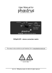
Enterprise Surveillance Manager. Version 5.4 Admin Manual This document describes the features and functions of ipConfigure’s Enterprise Surveillance Manager (ESM) Admin interface. IMPORTANT: BEFORE INSTALLING ESM, PLEASE READ ipConfigure’s PRE-‐ INSTALLATION GUIDE FOR ESM5.x. SOFTWARE PREREQUISTES MUST BE INSTALLED AND CONFIGURED PROPERLY PRIOR TO ESM. SEE: www.ipconfigure.com/support_documentation.html for instructions. Rev. 10.12 4111 Monarch Way | Suite 510 | Norfolk, VA | 23508 | p: 877.207.1112 | f: 832.201.0342 | www.ipconfigure.com ipConfigure ESM v5.4 Admin Manual TABLE OF CONTENTS SETUP AND LOG IN 3 4 4 ACTIVE X & FLASH – ESM Clients LOG IN SCREEN TAB FUNCTIONS USERS & GROUPS TAB 5 5 6 ADDING USERS ADDING GROUPS FEATURES & PRIVILEGES DEVICES TAB 7 7 8 8 9 9 10 10 10 10 10 11 13 16 17 17 17 18 GLOBAL DEVICES & LOCATIONS Adding Locations Adding Maps ARCHIVE SERVERS Server Settings Page Server Volumes Adding Archive Servers Server Streaming ADDING ACCESS CONTROL SYSTEMS Entity (Access Control) Settings Page ADDING CAMERAS Camera Settings Page Motion Detection Page Rules Engine Scheduling Recordings Parent Map Placement I/O Device Page LPR Camera Setup Page DEFAULTS TAB 18 RSS Feeds 18 Recording Schedules 20 Licensing REPORTING TAB 20 20 20 Dashboard Reports Scheduling Reports AXIS AVHS SUPPORT 21 Axis AVHS Support APPENDIX A 21 Interactive Monitoring Camera Application 2 ipConfigure ESM v5.4 Admin Manual SETUP AND LOGIN IN INTERNET EXPLORER SECURITY SETTINGS A web browser serves as the means of accessing ipConfigure’s Enterprise Surveillance Manager (ESM) client and admin interface. Although other Windows browsers are supported, ESM is optimized for Microsoft Internet Explorer 6.0 (or higher) as an Active X control is required by the ESM Client to load the ipConfigure Embedded Media Player (ipConfigure EMPPackage.cab) which is necessary for displaying MJPEG, MPEG4 and H.264 video streams in the browser. In addition, ESM requires the Adobe Flash plug-‐in be installed. NOTE: An Active X control is not required for ESM’s Admin interface. The following instructions are required and intended for the ESM’s client interface only. Ensure that each end user’s browser security settings are properly configured for downloading and installing ActiveX controls. Launch Internet Explorer and go to: Tools | Internet Options | Security tab. Select Internet zone and click Custom Level. Under “ActiveX controls and plug-‐ins” make the following changes (if applicable): A. B. C. D. E. F. G. H. I. Enable: Allow previously unused ActiveX controls to run without prompt Enable: Allow Scriptlets Enable: Display video and animation on a webpage that does not use external media player Prompt: Download signed ActiveX controls Enable: Run ActiveX controls and plug-‐ins Enable: Script ActiveX controls marked safe for scripting Enable: Automatic prompting for file downloads Enable: File download Enable: Font download After you are done, make the same changes to Local Intranet zone’s security settings. You will have to make these changes to each user’s workstation that will be using ESM’s client interface. It is also recommended that the URL for ESM be added to the list of Trusted Sites. Next download and install Adobe’s Flash plug-‐in for Internet Explorer. The download can be found at: http://get.adobe.com/flashplayer or http://www.adobe.com NOTE: If you are upgrading or updating to a new version of ESM you should uninstall the ipConfigure Embedded Media Player Active X control using Control Panel | Add Remove Programs and reboot. When you log back into ESM you will be prompted to install the updated ipConfigure Embedded Media Player ActiveX control. NOTE: Ensure that each client’s PC has Pop-‐up Blocker disabled and the URL for ESM has been added to the list of Allowed Sites (Tools | Pop-‐up Blocker | Pop-‐up Blocker Setting | Exceptions). NOTE: If using Internet Explorer 7 or 8 make sure that Compatibility View is checked (Tools |Compatibility View) and that the ESM URL has been added to the list of websites to display by default in Compatibility View. 3 ipConfigure ESM v5.4 Admin Manual NOTE: If a client’s PC is accessing ESM for the first time from outside your local network the ActiveX control may be flagged as being from an “Unknown Publisher”. This is a known issue with Internet Explorer. It is safe to proceed with the installation. LOG IN SCREEN To access ESM’s Admin interface open a browser and enter the IP address of the server where ESM has been installed followed by a forward slash and the word admin (Ex: http://192.168.100.11/admin). Once the login screen appears enter your User ID and Password. NOTE: User names and passwords are case sensitive. In the case of Active Directory authentication users names will be entered as: user_name_@active_directory_domain (ex. [email protected]). NOTE: The default Admin user name is administrator and the password is P@ssword. If you have been unsuccessful in three attempts at your password your account will be locked. Please contact ipConfigure Technical Support for assistance. Call: 1-‐877-‐207-‐1112, option 2. TIP: It is recommended that Administrators create two accounts just in case one of your accounts is locked due to incorrect password attempts. TAB FUNCTIONS The five main tabs (4 when using Active Directory authentication) are located in the left hand column of the ESM admin UI. Each tab corresponds to a number of settings pages related to the function of the tab. A summary of tabs and their functions is as follows: Reporting: ESM comes standard with 10 reports. These reports provide metrics of user activity, device status, storage utilization and server health. The Dashboard page provides a visual representation of four metrics by default: Camera Health, Device Alerts, Server Health, and Storage Health. Reports can be run on a programmatic basis and e-‐mailed to any number of recipients in .PDF format. Reports can also be printed and exported in .CSV and Excel format from within ESM admin interface. TIP: Custom reports can be written upon request. Please contact your ipConfigure sales representative for more information. Defaults: The Defaults tab allows ESM administrators to predefine settings (i.e. templates) for devices such as cameras, encoders and servers to facilitate the setup process. Other defaults include Recording Schedules which can be assigned to a single camera or groups of cameras and RSS feeds, which enable Admins to send notifications to ESM users and links to Internet or intranet sites. Notifications appear in the RSS feed dialogue box in the ESM client interface. Devices: This tab is used to add locations, servers, and devices to ESM. On the Camera Settings page, administrators define cameras settings for live view and recording (e.g. codec, resolution, frame rate and compression), configure motion detection windows, create rules for events and place camera icons for display in the Maps page of the client interface. Groups: This tab is used to add and manage group roles for locations and devices (Facility and Device Enrollment) and to assign rights to ESM’s client and admin features as well as portions of the interface. 4 ipConfigure ESM v5.4 Admin Manual NOTE: If ESM is installed using Active Directory authentication then the Group tab will be pre-‐populated with the same groups that are defined in Active Directory. Users: This tab is permits admins to create user names and passwords and assign users to Groups. NOTE: If ESM was installed with Active Directory authentication the Users page is not applicable. Currently ESM does not support mixed mode authentication. ADDING USERS Admins can easily add users to ESM by selecting the Users tab and right clicking on the Users icon Add User . Select and a dialogue box will prompt you to enter User Name, Password, Full Name and Email address. Once you have entered the user information click on the Create User button to save. NOTE: Users must be assigned to a Group in order to access cameras and system features. See next section. ADDING GROUPS Groups are created manually (or automatically via Active Directory if ESM was installed with the Active Directory authentication option) and assigned rights to specific locations, devices and users as well as interface features. The Groups tab allows administrators to quickly make changes to all the users assigned to the group and grant/deny or limit access to particular feature sets of the interface. To create a group select the Groups tab and right click on the Groups icon and select Add Group. You will be prompted to name the Group. Once named, you can now assign a location(s) and device privileges in the Facilities and Device Enrollment section by selecting or deselecting the check boxes associated with those locations and devices. NOTE: For Active Directory authentication, the group name entered must match pre-‐Windows 2000 Active Directory group naming convention. (i.e. DOMAIN\group) Be sure to click the Apply button at the top of the page after any change has been made to ensure your modifications are saved. 5 ipConfigure ESM v5.4 Admin Manual FEATURES & PRIVILEGES ESM can be customized by enabling or disabling features of the application in both the client and admin application. Simply check or uncheck the boxes to enable/disable the associated feature. TIP: Any number of Groups can be created. Admins can segment Users /Groups based on location, job function, managerial responsibility, etc. Settings The Email Addresses field allows ESM admins to input any number of email addresses and or distribution lists (separated by commas) of the recipients who wish to receive notifications in User Interface Rights | Alarm Monitoring section. NOTE: Email notifications in the User Interface | Alarm Monitoring section are supplemental to and dependent on email rules that have been defined in the Camera Settings| Rules page. In order for any email notifications to be sent, a SMTP Server, Port, Account and Password must be first defined for that Location’s Remote Archive Server. User Interface Rights Map Interface & Pan Tilt & Zoom: Grant/deny access to the Map pages and the user’s ability to Pan/Tilt and Zoom cameras by selecting or deselecting the appropriate options in this section. TIP: You may not want to allow users to move PTZ cameras because it will affect what is being recorded. Matrix View & Pan Tilt & Zoom: Grant/deny access to the Matrix page and the ability to create Custom and Shared layouts for other ESM users. Permit/deny control of Pan/Tilt/Zoom cameras from the Matrix page by selecting or deselecting the appropriate options in this section. Archive Search: Grant/deny access to the Archive page and related tabs: Search, Thumbnail, Library and the ability to Export video from said tabs. Global Access: Permits users to view all videos stored in the Library by all members of the assigned Group. NOTE: If this box is NOT checked, users will only be able to see their own clips they have added to the Library and no one else’s clips. Alarm Monitoring: Grant/deny access to the Alarm page and permission to perform searches based on events: Motion Detection, Alerts, System Errors & Updates that are selected on that page. ESM admins can enable/disable email notifications for a list of recipients (as defined in the Email Addresses section above) for selected events. NOTE: ESM will send email notifications for these events with “Enterprise Surveillance Manager Notification” in the subject line. LPR: Enable/disable access to ipConfigure's License Plate Recognition software for ESM (licensed separately) and related features and functions. Search and Real-‐Time tabs allow users to view and verify captured tags and subsequently Export related snapshots and video (if applicable) from the overview camera if installed. Check or uncheck ability to view, edit (Allow Changes) create and add tags to Watch Lists. 6 ipConfigure ESM v5.4 Admin Manual Admin Interface Rights Reporting: Enable/disable access to the Dashboard, the ability run reports from the Reporting page as well as schedule, delete and export reports from the Scheduler page. Defaults: Enable/disable permission to access and change ESM archive server defaults, camera defaults, RSS feeds, and recording schedules. Devices: Grant/deny access to view and change settings of ESM devices, including servers and cameras. Users: Grant/deny ability to create new users and or modify credentials. Groups: Grant/deny ability to make changes to Groups page. LPR: Enable/disable ability to change LPR camera settings. DEVICES TAB GLOBAL DEVICES & LOCATIONS Global Devices consist of all servers, cameras, encoders, and decoders that are connected to ESM based on a given location. Any device can be placed at a designated location in hierarchy of locations by simply dragging and dropping it under that location. An unlimited number of locations (with sub locations) can be added and managed from the Devices tab. Adding Locations To add a location simply right click on Global Devices and select Add Location. You will be prompted to enter a location name. Choose a name and click OK. The new location will now appear under Global Devices. This location will be at the upper most level of the hierarchy. Mass Update Devices enables ESM Administrators to push camera settings such as frame rate, resolution, image type, and compression to any camera(s) that is selected in the Global Camera Directory simultaneously. NOTE: This feature should be used with caution. Administrators should ensure that the selected cameras support the desired frame rate, resolution and image type before changes are applied otherwise errors will occur. Firmware Upgrade asynchronously uploads a firmware file to any Axis camera(s) at a given location. You can browse to the firmware file and upload into ESM to manage the upgrade process. Refresh will force the frame to reload if your changes do not appear. TIP: ipConfigure recommends using the camera manufacturer’s software to perform firmware updates. Be aware that firmware upgrades require that cameras be rebooted which will create a gap in recordings. ESM monitors cameras that are offline and will automatically restart after 30 seconds if a camera connection is lost. 7 ipConfigure ESM v5.4 Admin Manual Adding Maps Once you have created a new location under Global Devices the Map Setup page will load. Maps allow user to easily navigate to locations where cameras are installed. Each location map requires a text description and image file that is associated with that location. ESM includes a default map if none are loaded. To upload a map image browse to the directory where the image is located, select the file and click the upload button. Maps must be in either JPEG or GIF format. The page will automatically refresh with the map image. All maps uploaded into ESM will be available in Image Path drop down list. Now an icon can be placed on the map to denote its location. To create a hierarchy of nested locations right click on the first location and choose Add Location. Again the Map Setup page will be displayed. Choose a map from the Image Path drop down list or Upload a new map for this location. Next, click on the Parent Map Placement tab. You will notice the “parent” map is displayed on the page. You are now able to drag and drop the blue Location icon anywhere on the map to indicate an ESM installation. This icon will appear on the ESM client interface MAPS page and is used to drill down to a sub-‐location or building. You can continue to add sub-‐locations following the same process or add buildings to this location. NOTE: ESM does not support dragging and dropping between remote locations. If you want to rearrange the hierarchy of locations or assign an existing archive server to another location, you can create a new location and delete the current one. However prior to deleting the current (old) location make sure to Disconnect Location by right clicking on that location first. When the new location has been added, right click on that location and select Link to Server (archive server) and all the settings will be preserved. In order to add a building under a location you must first link that Location to an ESM Archive Service using the right click option Link to Server (as described in more detail below). Once linked, you can right click on the location and select Add Building. You will be prompted to choose or add a map/ floor plan for this building in the same manner as you did when you added a location above. NOTE: Camera icons are placed on building maps in the Devices|Camera Settings |Parent Map Placement page. ARCHIVE SERVERS Once you have created a location and uploaded a map you can add a server that will record and store video associated with that location. These recording and storage servers are collectively known as “archive” servers. However before doing so you must first link to the ESM Remote (Archive) Service. To add an Archive server right click on the location and select Link to Server. You will be prompted to enter the IP address of the server. Click Ok to link to server. You will notice that a Remote Service has been created under that Location and an Archive Server listed below it. NOTE: ipConfigure’s ESM Archive Server software must be installed on this server prior to the linking process. Once the Remote Service successfully links to the server you can then select your time zone and input the physical address information of the server if so desired. Next you will need to configure the Archive Server you just added. 8 ipConfigure ESM v5.4 Admin Manual Server Settings Page On the Archive Servers settings page ESM admins can enter a Description for the server and enable or disable it by checking or un-‐checking the Active box. TIP: The Active checkbox can be used to make backup ESM Archive servers available in the event that the main archive server goes off line or fails. Set up a backup server using the same setting however leave the Active box unchecked until needed. The LAN IP Address is the private (true) IP address of the Archive server. The WAN IP Address is the IP address that will get returned to the client browser when archive video is streamed during playback. The ESM URL is used by the Archive server to know where to find the ESM Management server. NOTE: The ESM URL field should almost never be changed directly by a customer as it is automatically populated when you perform the Link to Server procedure. In order to permit ESM to send Email Notifications, admins must configure the SMTP Server IP Address, Port, Account, Password, Sender and the Recipients email addresses on this page. Finally, the Library Storage determines the maximum allocated disk space to be used for archived video clips that are sent to The Library. NOTE: The Library folder resides on the server where ESM is installed in the archive root: \ipConfigure \library folder and not on the end user’s local machine. Server Volumes To add a server volume, right click on the Archive Server and select Add Server Volume. You will be prompted to enter the drive letter and a root path for the archive (e.g. c:\archives). Volumes can consist of any Windows drive letter. After the root archive path is defined you can specify a recording retention time of Short, Medium and Long which can be assigned to any camera in the Camera Settings page. The video associated with that camera is stored for the duration that is specified after which ESM will be record over the video from the oldest date to the most recent (FIFO). NOTE: Each Archive Server must have at least one storage volume assigned prior to adding cameras. ESM supports multiple volumes. Cameras can be assigned to unique volumes in the Camera Settings page. Hard disk quotas can be set in the Max Disk Usage (GB) field. Unique to ipConfigure’s ESM is the Motion Grooming algorithm. Motion Grooming works on video that has been continuously recorded and where motion is detected. The algorithm will analyze video streams and determine where there is no motion and automatically delete it thus freeing up disk space. Admins can set the number of days continuous recordings will be maintained before the Motion Grooming algorithm starts its process. Furthermore, the Motion Grooming Buffer provides a pre-‐motion and post-‐motion buffer (in seconds) so that video maintains continuity before and after the motion event. NOTE: In the event that the Max Disk Usage is met, ESM will delete the oldest archive video (across all cameras regardless of the camera’s retention time) to free up more recording space. 9 ipConfigure ESM v5.4 Admin Manual Adding Archive Servers To add a second ESM Archive server right mouse click on the Remote Location Service and select Add Archive Server. Choose Default Archive Server and enter the IP address of the second server. After you have added an Archive Server it is necessary to add a storage volume(s) to that second server as previously described. Server Streaming The first version of server streaming is included in ESM 5.4 for the Silverlight clients. This is only support for non-‐IE browsers using the Silverlight live streaming client. The IE client will remain the same using direct connection to the camera for all live streaming. Server streaming will support MJPEG only and will not support for MPEG-‐4 or H.264 live streaming for the Safari/Silverlight clients. ADDING ACCESS CONTROL SYSTEMS Access control systems can be added by right clicking on the building and selecting add system and then choosing the appropriate system. Enter the name as it will be displayed. Entity (Access Control) settings page There are five (5) tabs used on the access control settings page: Settings: contains Entity information such as a name, type, location, and box to enable/disable Rules: set up rules to associate with the access control device Parent Map Placement: places icon on map Associations: choose which cameras to associate with access control device Relationships: identifies where the entity or device is on the hierarchy tree ADDING CAMERAS One or more cameras can be added to locations or buildings by right clicking on the building and selecting Add Camera. You will note a single camera type labeled Default Camera, if additional default profiles are desired they can be created under the Defaults tab. The Auto Discovery feature is available for all Axis cameras and can be performed by right mouse clicking on the building and selecting Auto Discover Cameras from the menu. ESM will list all Axis cameras found on the network under Global Devices. Admins can quickly modify the settings of the newly discovered cameras in the Camera Settings page. NOTE: Once a camera has been added you must assign it to a Group in order access to that camera. Cameras that have not been assigned to a Group(s) are depicted by the new camera icon . TIP: Any camera or device can be moved to another location (or building) in the Global Devices tree by dragging and dropping the icon to another location. This only affects how the cameras are displayed in the tree and not their Archive Server settings. 10 ipConfigure ESM v5.4 Admin Manual Camera Settings Page The Camera page consists of four tabs: Camera Settings, Motion Detection, Rules, Schedule and Parent Map Placement. The Camera Settings page is where admins define how a camera is being used by ESM, selects manufacturer and model, where it records to and how it is configured for live view and recording. The Description is self-‐ explanatory. The camera’s description is not only displayed under Global Devices directory but also in the ESM client interface. TIP: Keep camera descriptions to 60 characters or less -‐ otherwise the text will be clipped when displayed in a pop-‐up camera window and on the Matrix page. ESM is primarily used for surveillance application; however, the application supports the use of IP cameras for non-‐ surveillance applications as well. Admins define how a camera is used in ESM via the Camera Application drop down list which can be one of the following: Surveillance, LPR (License Plate Recognition), Interactive Monitoring and Workstation. An Interactive Monitoring Camera Application can be used where bi-‐directional audio and video is required like: Central Station Monitoring, Telemedicine, Distance Learning and Web Conferencing. What is unique about this Camera Application is that it used in conjunction with an Axis decoder for displaying video on a CRT or public view monitor. You must first add a decoder to ESM and configure the IP address in order to associate a decoder with the camera used for Interactive Monitoring. Right click on the location and choose Add Decoder and select the Axis 292. A decoder will be added to the Global Device directory. Click on the Decoder icon and the Decoder Settings page will be displayed. Enter the Name, Type, URI (IP address), user name and password. Now you will be able to associate this decoder with a camera used for Interactive Monitoring. NOTE: Recording is not available when an Interactive Monitoring and Workstation Camera Application are selected. When an Interactive Monitoring camera is selected for live viewing from the ESM client interface via the Maps and Matrix pages, the pop-‐up window displays the live video stream along with audio (if enabled) and audio controls (speaker mute/volume, microphone mute/volume). Additional functions include: Auto Focus and Zoom for PTZ cameras, enable/disable remote display monitor (decoder), and PTZ Presets. See ESM User Manual for a description of these icons and their functions. Workstation is used in conjunction for live viewing only on a PC/workstation. It differs from the Interactive Monitoring camera type because it is not associated with a decoder. The PC/Workstation does the decoding for display on its monitor. Like Interactive Monitoring no recording function is available for this Camera Application so the camera icon in the Global Devices directory will appear with a red x . The functions available via the ESM client UI in the live view pop-‐up window only include PTZ presets (if applicable) microphone and speaker mute/volume controls. Surveillance and LPR Camera Applications is self-‐explanatory. Most cameras used in ESM will be Surveillance Camera Applications. 11 ipConfigure ESM v5.4 Admin Manual See ESM v5.4 Supported Devices document online for a list of cameras and encoders supported in this version. The selected Camera Type will determine some of the other settings are on this page. In the Camera Settings pane: Pan/Tilt/Zoom checkbox, Guard tour, PTZ Setup and Tour Interval check boxes/functions are only available if a PTZ camera has been selected from Camera Type list. The PTZ Setup button links to the camera manufacturer’s web interface and it is how administrators configure PTZ Presets and Guard Tours. Prior to configuring PTZ Presets, populate the IP address of the camera in Live View section and enter the user name and password. Click the Apply button to save your changes. NOTE: The PTZ Preset name in the camera’s interface must match identically to the Preset names in ESM in order to function properly. PTZ Presets will appear in ESM’s client UI camera pop-‐up windows. The other checkboxes and settings on the Camera Settings pane (Enabled, Covert Camera and Rotate Video) functions are not affected by which Camera Type is selected. Check the Enabled box to arm the camera for live view and recording. NOTE: If the Enabled box is NOT checked the camera will NOT be visible in ESM user interface NOR will it record. Any camera can be depicted as a Covert Camera in the ESM client interface (whether or not it is actually a “bullet” or a “pin-‐hole” camera). Checking this box changes the camera icon that is displayed in the ESM client interface (Maps Page) to and elsewhere to indicating the camera is being used for covert surveillance. ESM establishes a direct connection from the browser to the camera(s) for live view; as a result the settings in the Live View pane are independent of the settings in the Recording pane. Credentials that are entered in the Authentication pane must first be set in the IP camera’s UI and match exactly in ESM. NOTE: Because ESM uses dual IP cameras connections, it is possible that cameras may be viewable in the Maps and Matrix pages and not be recording due to the archive server being offline or other error. In Live View pane enter the IP Address and Port of the camera. Select the desired connection protocol between the browser and the camera of HTTP or HTTPS. Live View Resolution (for camera pop-‐up windows in the ESM client UI) is determined by the Resolution setting in the Recording pane. The Live View resolution displayed in the Matrix page depends on what layout has been selected. ESM chooses the best resolution from the list of supported camera resolutions to fit the selected layout in the Matrix without stretching or distorting the image. NOTE: HTTPS uses SSL encryption between the requesting browser and the camera. Because the communication protocol is encrypted in the camera, it has a negative effect on performance (specifically frame rate). HTTPS is only applicable to Axis and Sony cameras in this version of ESM. ipConfigure recommends using HTTP. Image Type is determined by the selected Camera Type. Your choices will be any of the following codecs: MJPEG, MPEG4 and H.264. Check Audio if that is desired and supported natively by the camera. ESM currently supports audio for Axis and Sony cameras that support H.264 codecs only. TIP: Select MJPEG for live viewing as it requires less CPU to display and exhibits less latency than MPEG4/ H.264. 12 ipConfigure ESM v5.4 Admin Manual Choose the amount of Compression to apply to the Live View video stream. A high Compression percentage will result in lower image quality and smaller file sizes (lower bandwidth utilization). Conversely a low Compression percentage will result in higher image quality and larger file size and bandwidth utilization. Select a Frame Rate for live view that suits your requirements. In most cases Frame Rate settings will be adjustable from 1 to 30 Frames Per Second (FPS). Higher frame rates will result in larger file sizes and require more bandwidth. TIP: A compression percentage of 40% and frame rate of 7 FPS for live view is adequate in most use cases. Adjust these settings according to your requirements keeping in mind the impact on bandwidth and storage. NOTE: Certain megapixel cameras supported by ESM are not capable of streaming up to 30 FPS in MJPEG. Please check the camera manufacturer’s specifications for frame rate capabilities. If a camera is configured with an unsupported frame rate, ESM will not be able to view or record the video stream and an error will the displayed. Cameras can be assigned to any predefined Archive Server by selecting it from the drop down list. Once it has been assigned to an Archive Server you can select the Archive Server Volume where the recorded video will be stored, and for how long, using the Storage Days drop down (as defined when you added an Archive Server). In the Recording pane you enter the IP Address and Port number of the camera. In most cases this will be the same as the Live view settings unless you are exposing your camera(s) via the Internet. For more information on this procedure please see www.ipconfigure.com/ support for “Porting ESM through a Firewall” documentation. Enter the desired camera’s Image type (MJPEG, MPEG, H.264), Image resolution and if recorded Audio is desired (these settings will be dependent on the Camera Type selected). NOTE: Audio for live view and recording is only available for Axis and Sony cameras that support H.264 compression in this current version of ESM. The PreBuffer and PostBuffer frames allow ESM to capture a number of frames prior to and after events that are triggered by the ESM Motion Detection algorithm. A Motion Detection grid and recording schedule must be configured in order for these parameters to be applicable (see next section). Still Image Quality determines the image quality (High, Medium or Low) that saved by the Capture Frame process (ESM client interface) and conversely the amount of compression that is applied. The default setting is Medium. Motion Detection Page ipConfigure’s motion detection engine offers low false recording, depth perception and highly accurate outdoor motion detection. The Motion Detection algorithm analyzes every pixel on the grid line in conjunction with the Motion Intensity and Motion Sensitivity settings. The Motion Intensity setting determines the number of pixels on the line that have to change in order to trigger a motion detection flag. For example, setting Motion Intensity to a low number will only trigger flags for smaller the objects and a high number will trigger flags only for larger objects. Motion Sensitivity determines the rate of change a pixel has to exhibit over time in order to trigger a motion detection flag. For example, set this number to a high value to trigger motion flags for slow moving objects and lower for fast moving objects. 13 ipConfigure ESM v5.4 Admin Manual TIP: To test your Motion Detection settings open up another browser window and login to the ESM client interface. Navigate to the Matrix page and select the same camera you are configuring in admin interface from the Global Camera Directory. Check the Motion Cycle check box and observe the rate at which the red squares replace the green squares when motion is detected in the field of view. Adjust the grid lines and sensitivity to suit your requirements. New enhancements have been made to this version of ESM which allow admins to resize the motion detection lines and draw rectangles and squares. Other improvements include the addition of preset Gird Patterns and Horizon Detectors, a Pixel Counter to measure CPU load, and the ability to Crop Detectors. The right click menus on the Motion Detection page are context sensitive. Different options are presented based on if you click on the grid line or off the grid line. When you click on the red gird line the menu (to the left) will be displayed. The Resize feature allows Administrators to stretch and shorten the line. Lines can also be converted into rectangles or squares by clicking the green handle at one end of a line and dragging it to the desired size. NOTE: Using rectangles/squares for motion detection increases CPU utilization. To see the impact right click on the VMD windows and select Toggle Pixel Counter. ipConfigure suggests using a smaller grid (20x20) inside a larger grid (10x10) to accomplish the same effect as a rectangle or square. Delete Detector removes the selected grid line from the page while Delete All Detectors removes all gird lines from the page. Convert to Horizontal Line and Convert to Vertical Line will change the orientation of the selected grid line as indicated. Bring to Front and Send to Back operate like familiar graphics applications whereby the selected line is sent to the foreground or background. Example: Grid A Detectors (10x10) above left. Grid A Detectors (10x10) plus Grid B Detectors (10x10) above right. When you click off the red grid line on the image the following context menu will be displayed (below). Add Horizontal Line Detector simply adds one horizontal grid line while Add Horizontal Line Detectors (10) adds ten grid lines on the image. Add Vertical Line Detector and Add Vertical Line Detectors (10) function the same except lines are added in a vertical orientation. 14 ipConfigure ESM v5.4 Admin Manual A few presets grid patterns have been added as defaults including: Grid A Detectors (10x10), Grid B Detectors (10x10) and Grid C Detectors (20x20). Admins can use the Crop Detectors or Delete Detectors to effectively create exclude zones from the image. TIP: Grid patterns can be nested within other grid patterns to create tighter grids. See Example at the top of the page. Add Horizon Detectors adds depth perception by mimicking the horizon effect. Horizon grids operate on the premise that the further away the object is from the camera (i.e. small objects) the more lines are required to trigger a motion flag. Conversely the larger the object, the fewer lines are necessary to trigger a motion flag. Toggle Over-‐Scaling is selected if the source image resolution is smaller than the motion detection window’s resolution. The image can be stretched (“over scaled”) to fill the entire motion detection window. If the source image is larger than the motion detection window, it is down sampled to fit within the window. NOTE: The source image resolution is taken from the Camera Settings page| Recording pane. The image displayed is a still image, not live video. Toggle Pixel Counter displays the number of pixels that are being analyzed by the motion detection algorithm. This indicator is useful in determining the CPU load. Admins can reposition the Pixel Counter on the page by clicking-‐and-‐dragging it to the desired position. The Crop Detectors feature deletes all grid lines that are touching the dark gray cropping window that you have drawn. To draw a cropping window left click on the image (not on a grid line) and continue to hold the mouse button down while dragging over the area where the detectors will be deleted. Release the left mouse button and right click to bring up the context menu. Select Crop Detectors. You are effectively creating an “exclude window” for the motion detection algorithm to ignore. You could also use this cropped area to insert another grid pattern. NOTE: There is no undo function. If you make a mistake you will have to recreate the grid pattern from the start. Example: A Cropping Window (dark gray) on the left wall. Right click context menu shown. Rules Engine Version 5.4 includes an advanced rules engine that enables users to select certain Events (Camera Online, Camera Offline, 15 ipConfigure ESM v5.4 Admin Manual Error, Motion Detected, and Motion Ceased) that trigger certain Actions (Cancel Force Record All, Force Record, Email, Log Alert and Log Update). Furthermore, Administrators can also define Conditions (Delay, Duration and Value) that must be met or checked periodically before an Action is triggered. Conditions specifically apply to use of a Barix Barionet 100 Ethernet Device Server (I/O) in this version of ESM. NOTE: Events are specific to one (1) location and do not have an affect other ESM Remote Location Servers. The most common use of Events would be to send e-‐mail notifications or make changes in recording settings. For Example: If Motion Detected on Front Door Camera #1 then Force Record on Lobby Camera #2. When Motion Ceased on Lobby Camera #2 then Cancel Force Record. Adding a Rule To add a rule, click the Add button. The Rules page will be displayed. Select an Event Device from the drop down list and an Event. Event Devices can be a System event (e.g. errors) or a device event (e.g. camera or encoder). The Event Device selected determines what Events are available. If Event Device | System is selected the Event types can be one of the following: Error, Motion Detected and Motion Ceased. If Event Device is a camera the Event types will be: Error, Motion Detected, Motion Ceased, Offline and Online. If the Event Device is a Barix device, the Event types will be: Error, Offline, Online, and all the available Inputs, Outputs and Relays in either an Activated or Deactivated state. Next click the Add button to add an Action. The page will refresh with Action Devices and Actions. Select an Action Device from the drop down list and an Action. The Action Devices and Actions behave the same as Event Devices and Events. Your choice of Action Device affects what Actions can be selected. If an Active Device | System is selected Force Record All, Cancel Force Record All, Email, Log Alert, Log Update will be your choices. Force Record All over rides the Recording Schedule for a particular camera and activates the recording process if triggered by the Event. Optionally you can define the Duration to Force Record (in seconds) although ESM by design records in one minute blocks. Cancel Force Record All returns the camera to its particular Recording Schedule if triggered by the Event. An Email Action will send an email alert with “Enterprise Surveillance Manager Notification” in the subject line to the recipient(s) defined in the Email field if triggered by the Event. Admins can also program a Delay or wait state before initiating any Action. Log Alert and Log Update will post an alert or update to the Alarm page in the ESM client interface. If the selected Action Device is a camera or encoder then Force Record, Cancel Force Record, Enable and Disable will be your choices. Force Record and Cancel Force Record operate as previously described. Enable and Disable will put the camera online or offline respectively (effectively checking and uncheck the Enabled box in the Camera Settings page). Administrators can program a Delay or wait state before a camera is put online or taken offline. If the selected Action Device is a Barix Barionet 100, the Actions include: Pulse and Toggle relays as well as Enable Disable, Activate and Deactivate inputs, outputs and relays. All of these Actions can be programmed with a Delay and Duration. Once all information is entered click the Update or Insert button and you will see a description of the Action has been added under the Actions pane. It can be Edited Deleted at any time. You can also add another Action by clicking the Add Action button. or 16 ipConfigure ESM v5.4 Admin Manual TIP: For more information on how to setup and configure a Barix Barionet 100 device please see: http://www.barix.com/downloads/Barionet_Family/51/ Optionally Conditions can be applied to a Rule which will effect if, when or what condition must be met (or not met) in order for the Action to be taken. Condition Devices are listed in the drop down. NOTE: Currently, Conditions are only applicable to the Barix device. In future versions of ESM Conditions will be applicable to I/O ports on any device. To add a Condition, click the Add Condition button . Next select Device Port which will list available I/O ports in the drop down list. Operators include; is equal (=), is not equal (! =), is greater than (>), is less than (<) is greater than or equal to (>=) and less than or equal to (<=) and between. Value 1 will depend on the selected Device Port (or what is connected to it). For example: if the Device Port is a digital input or output, Value 1 could be a 1 or 0 (for on/off). If the Device Port is connected to an analog input or output, Value 1 could be any positive number. Value 2 is only used if the Between Operator is selected. It behaves like Value 1 for the device port and is used to create a comparative condition between Value 1 and Value 2 in order to trigger an Action. Once you have defined the Condition click the Insert button and you will notice a Description of the condition has been added to the Condition pane. TIP: The Barix Barionet 100 has many possibilities – too many to list in this manual. Please see the Barix web site for possible installation scenarios. Scheduling Recordings The Scheduling page allows admins to select predefined Recording Schedules and assign it to the selected camera. Simply choose from the drop down list the desired Recording Schedule and ESM will display the Recording Schedule on that page. Schedule can be displayed by the Day, Week, Month or Timeline. NOTE: The list of available Recording Schedules is created in the Defaults tab. See DEFAULTS section for more information. Parent Map Placement This page allows for the placement camera icons over a map image. Simply click and drag the icon to appropriate location on the map. The Camera Type in the Camera Settings page will determine what icon is presented. The sun green shape icon shaped icon represents a PTZ camera and candy striped if has covert status . The rectangular represents a fixed camera. If the camera was assigned covert status on the Camera Settings page the camera icon will have a red and white candy striped color and black and white checkered color if being used for License Plate Recognition. Icons can be rotated to show the direction they are pointing by either selecting the degree of rotation from the Icon Rotation drop down list or right clicking on the icon to bring up a menu to Rotate Clockwise or Counter Clockwise. I/O Device Page If a Barix Barionet 100 Device is added to ESM (similar to adding cameras) you will be presented the I/O Devices Settings Page, Rules and Parent Placement pages. The Rules and Parent Placement pages behave just like they do 17 ipConfigure ESM v5.4 Admin Manual with Camera Settings. The I/O Device Page allows administrators enter Device Name, Device Type (Only Barix Barionet supported currently) IP Address, Port and Credentials for this device. An Archive Server can be associated with this device to record alarms and log events. “User-‐friendly” names can also be assigned to specific inputs/outputs. LPR Camera Settings Page If an LPR camera is being used for ESM you will notice a slight difference in the Camera Settings page insofar as there will be a field for an Overview Camera. The “Overview Camera” is defined as a Surveillance Camera in ESM but is tied to an LPR camera. An Overview Camera is a secondary camera may be used to capture video related to the LPR camera (since the LPR camera uses still images for detection, not full motion video). If so installed and configured, video from this overview camera will be displayed along with a still image taken from the LPR camera in the ESM client UI | LPR Search Page. NOTE: ipConfigure’s LPR is an (additional) licensed feature of ESM. It requires the use of an Axis P1346 and special firmware which has been optimized by Axis for use in LPR application. A separate software application called the LPR Calibrate tool is used to configure the LPR application and transfer settings to ESM. Furthermore specific plate font information is required in order to obtain high accuracy results. Please ask your ipConfigure Sales Representative for more information about LPR and the availability of the LPR Calibrate utility. Defaults Tab The Defaults tab is used to create templates for certain devices used by ESM (Archive Servers, Cameras, and Encoders) and for creating Recording Schedules and RSS Notifications as well as Licensing. Once created the Default information populates the fields on the page thus facilitating the set up process. To create a Default, right click on the Archive Server Defaults icon or Camera Defaults icon to Add a new default. The device settings page appears for that given device. Input the information in each section of the page and click the Apply button to save your changes. Now when you right click on the Remote Location Service in the Devices Tab |Global Devices you can select Add Archive Server +Default Archive Server which will contain the information that you have just entered on the Archive Server Defaults page. The same would be true for adding a Default Camera when you right click on a Location Devices Tab | Global Devices or Building under the . You can add any number of defaults to ESM. Defaults are used more commonly for cameras than any other device. RSS Feeds Notifications can be sent by ESM Administrators to all ESM users via the ESM client UI’s RSS Notification area. Notifications are displayed like an RSS feed and cycle through all RSS feed that are enabled in the list. These notifications can reference an external or internal web site 18 ipConfigure ESM v5.4 Admin Manual or be short messages. ESM users can click on the RSS feed and be linked to another web site. Any feed can be enabled or disabled by an administrator. To Add a RSS Notification left click on the RSS icon and the RSS page will appear on the right. Enter the Source text which will be shown between the time and the date in red text and a Description (which will be streamed across the RSS Notification area) and the URL which ESM users will click to hyperlink. Lastly click the Add button. Any number of RSS Feeds can be added to ESM. NOTE: If no URL is entered ESM will return a “Server Error 404” for no page found when end users click on the link. Recording Schedules Recording Schedules are assigned to a camera(s) in the Device tab | Camera Settings |Scheduling page. These schedules are defined in the Defaults tab. NOTE: ESM ships with a default schedule (“mon-‐fri 8AM -‐5PM”) which records continuously at 5 frames per second during normal business hours (8AM – 5 PM) and motion only during non-‐business hours. You can modify this schedule to suit your requirements or create new ones. To create a new Recording Schedule, right click on the Schedules icon Default and choose Add Schedule and you will be prompted to name your new schedule. Enter a name and click OK. A calendar will be displayed. Double click anywhere on the calendar to recall the Appointment page. This page operates similarly to Microsoft’s Outlook calendar. Enter a Description for this Recording Schedule and select a Recording Mode: Motion Only, Continuous or Disabled. NOTE: By default ESM records continuously unless Disabled Recording Mode is specified. Select a Frame Rate, a Start Time and an End Time. You can choose an All day event or recurring event. If Recurrence is selected you will be able further define how often the recurrence will occur (Hourly, Daily, Weekly, Monthly, Yearly) and the Range of Recurrence where you can specify an End Date, No End Date or after so many occurrences. After you have entered the information click the Insert button to save your changes. The Recording Schedule will now be available in the drop down list in the Devices tab| Camera Settings| Scheduling page. To modify an existing Recording Schedule double click on it from the list of Schedules. Double click anywhere on the calendar and you will be prompted to edit this occurrence or the series. The Appointment page will be displayed for you to edit the Recording Schedule. Click on the Apply button to save your modifications. 19 ipConfigure ESM v5.4 Admin Manual Licensing This section under Defaults refers to the licensing portion. To request a license and upload a new license, follow these steps: Log into Admin and click on the Licensing button under Defaults. By default, it is installed as a demo, as the below screenshot demonstrates. Click export to create an Activation request. Email the licensing request to [email protected] to create an eSupport ticket. Once you have emailed the request, the licensing file will be mailed back to you using eSupport ticket. Select your licensing file through the Browse button and then upload the license file onto the ESM admin page. Once you have uploaded your license, your screen should look similar to this screenshot if your license has been successfully applied. Simply, verify that your license count is correct. Reporting Tab ESM comes standard with 10 reports. These reports provide metrics of user activity, device status, disk storage utilization and server health. The Dashboard page provides a visual representation of four metrics by default: Camera Health, Device Alerts, Server Health, and Storage Health. Click on the Location icon to display the Dashboard for that specific location. To run a detailed report on the Dashboard metrics simply click on the pie chart. The Reports page will be displayed. Chose the Run button to display the results of the report on the page. Reports can be run on a programmatic basis and emailed to any number of recipients in .PDF format. Reports can also be printed and exported in .CSV and Excel format from within the ESM admin interface. The Reporting page allows any ESM report to be selected from a drop down list with a date range (Start Date and End Date). The Scheduler page allows for certain reports to be sent out on a periodic basis to selected recipients. Click the Add button to display the Scheduler page. Select the desired reports to be sent using the arrows buttons and the Frequency and Time at which the reports are sent along with the list of Recipient(s) Email addresses. 20 ipConfigure ESM v5.4 Admin Manual TIP: Emailing of reports allows for administrators to keep track of system health without being logged into the ESM admin interface. ipConfigure recommends that admins email themselves the Camera Exceptions report or Camera Status report on a daily basis. These reports will give you insight into problematic conditions. AXIS AVHS SUPPORT Axis AVHS is a zero configuration option supported on new models of Axis IP Cameras. This provides the ability to plug a camera into a network and automatically subscribe to a cloud service for hosting. A cloud server is setup at cloud.ipconfigure.com which includes the AVHS functionality to support all Axis AVHS cameras. More info on AVHS http://www.axis.com/products/avhs/index.htm 21 ipConfigure ESM v5.4 Admin Manual APPENDIX A: INTERACTIVE MONITORING CAMERA APPLICATION ESM Administrator UI Setup Patient Room #105 Speaker Microphone Nurse Workstations Axis 215 PTZ Camera Axis 211 Headset w/ Mic. Room Monitor Axis Decoder Patient Room 10x Speaker ESM Client UI -‐ Pop Up Window Controls Microphone Axis 215 PTZ Camera on off disabled mic speaker Room Monitor Axis Decoder auto focus monitor ESM Interactive Monitoring Camera Application Rev.10/12 ©2011 ipConfigure Inc. The material in this document is copyrighted and not to be used or reproduced without the express written consent of ipConfigure. Information in the document is subject to change without notice. 22