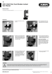
1
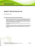
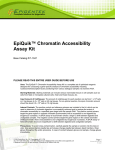
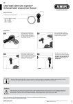
EpiSonic TM multi-functional bioprocessor User Manual 1000 Series DNA SHEARING CHROMATIN SHEARING CELL DISRUPTION CELL LYSIS HOMOGENIZATION AND MORE... Complete Solutions for Epigenetics Manufactured in the USA • Epigentek Group Inc. Web: www.epigentek.com • E-mail: [email protected] Tel: 1-877-374-4368 (USA) • Tel: 1-718-484-3990 (Int) • Fax: 1-718-484-3956 EpiSonic TM multi-functional bioprocessor WARRANTY INFORMATION Epigentek warrants that the EPISONIC 1000 sonication generator device is free from defects in material and workmanship under normal use and service for twenty (20) months from the date that the warranty period begins, unless otherwise indicated. Warranty periods begin on the date of delivery. All warranties apply only to the original purchaser of this product. Epigentek’s obligation under this warranty is limited to the repair or replacement at its sole discretion of any product or part thereof if the product is deemed to have a manufacturing defect upon examination by Epigentek or its authorized repair service provider. The sample processing horn is covered under a 6 (six) month warranty from defects in material and workmanship under normal use and service. Included soundproof enclosure box, cables, tubing, and tools are not covered by any warranties. Discoloration or paint wear is not covered by any warranties. Any warranties shall cover only manufacturing defects and do not cover any damage resulting from accidents, misuse, abuse, neglect, modifications, repair or service by any unauthorized parties, exposure to extreme temperatures, exposure to acids or chemical solvents, failure to comply with the instructions in this user manual, or maintenance not in accordance with any information contained in literature accompanying the product. Any unauthorized modifications, repair, or servicing by parties not approved by Epigentek shall void any warranties. All returns for repairs or replacement must be accompanied with a Return Merchandise Authorization number (RMA #) which can be obtained through Epigentek’s customer service department. Equipment should be returned in the original packaging. If you no longer have the original packaging, you will need to contact Epigentek for approved packaging methods. Damage occured from return shipping due to poor packing is not covered by this warranty. WHEN RETURNING ANY MATERIALS TO EPIGENTEK, YOU MUST CERTIFY THAT THE MATERIALS BEING RETURNED ARE FREE OF ANY HAZARDOUS, INFECTIOUS, OR RADIOACTIVE SUBSTANCES, AND ALL PARTS HAVE BEEN PROPERLY DECONTAMINATED. EPIGENTEK GROUP INC. EpiSonic™ Multi-Functional Bioprocessor 1000 Made in the United States of America USA Phone: 1-877-374-4368 International Phone: 1-718-484-3990 Ordering E-mail: [email protected] Support E-mail: [email protected] Website: http://www.epigentek.com PAGE 2 | EPISONIC™ WWW.EPIGENTEK.COM | [email protected] Complete Solutions for Epigenetics TABLE OF CONTENTS Precautions . . . . . . . . . . . . . . . . . . . . . . . . . . . . . . . . . . . . . . . . . . . . . . . . . 4 Safety Precautions . . . . . . . . . . . . . . . . . . . . . . . . . . . . . . . . . . . . . . . . . . . . . . . . . . . . . 4 Equipment Protection . . . . . . . . . . . . . . . . . . . . . . . . . . . . . . . . . . . . . . . . . . . . . . . . . . 4 Introduction . . . . . . . . . . . . . . . . . . . . . . . . . . . . . . . . . . . . . . . . . . . . . . . . 5 Background Information . . . . . . . . . . . . . . . . . . . . . . . . . . . . . . . . . . . . . . . . . . . . . . . 5 Technical Specifications . . . . . . . . . . . . . . . . . . . . . . . . . . . . . . . . . . . . . . . . . . . . . . . . 5 Components . . . . . . . . . . . . . . . . . . . . . . . . . . . . . . . . . . . . . . . . . . . . . . . . 6 Parts Supplied . . . . . . . . . . . . . . . . . . . . . . . . . . . . . . . . . . . . . . . . . . . . . . . . . . . . . . . . 6 Rear Panel Diagram . . . . . . . . . . . . . . . . . . . . . . . . . . . . . . . . . . . . . . . . . . . . . . . . . . . . 6 Installation . . . . . . . . . . . . . . . . . . . . . . . . . . . . . . . . . . . . . . . . . . . . . . . . . 7 Pre-Assembly . . . . . . . . . . . . . . . . . . . . . . . . . . . . . . . . . . . . . . . . . . . . . . . . . . . . . . . . . 7 Main Assembly . . . . . . . . . . . . . . . . . . . . . . . . . . . . . . . . . . . . . . . . . . . . . . . . . . . . . . . . 8 Setup Diagram . . . . . . . . . . . . . . . . . . . . . . . . . . . . . . . . . . . . . . . . . . . . . . . . . . . . . . . . 8 Operation . . . . . . . . . . . . . . . . . . . . . . . . . . . . . . . . . . . . . . . . . . . . . . . . . . 9 Touchscreen Control . . . . . . . . . . . . . . . . . . . . . . . . . . . . . . . . . . . . . . . . . . . . . . . . . . . 9 Handling Your Samples . . . . . . . . . . . . . . . . . . . . . . . . . . . . . . . . . . . . . . . . . . . . . . . . . 13 Optimization Suggestions . . . . . . . . . . . . . . . . . . . . . . . . . . . . . . . . . . . . . . . . . . . . . . . 14 Example Protocols . . . . . . . . . . . . . . . . . . . . . . . . . . . . . . . . . . . . . . . . . . . 16 Pre-Optimized DNA Shearing . . . . . . . . . . . . . . . . . . . . . . . . . . . . . . . . . . . . . . . . . . . . 16 Pre-Optimized Chromatin Shearing . . . . . . . . . . . . . . . . . . . . . . . . . . . . . . . . . . . . . . . 16 Caring For Your Device . . . . . . . . . . . . . . . . . . . . . . . . . . . . . . . . . . . . . . . . 17 After Operation . . . . . . . . . . . . . . . . . . . . . . . . . . . . . . . . . . . . . . . . . . . . . . . . . . . . . . . 17 Maintenance . . . . . . . . . . . . . . . . . . . . . . . . . . . . . . . . . . . . . . . . . . . . . . . . . . . . . . . . . 17 Accessories . . . . . . . . . . . . . . . . . . . . . . . . . . . . . . . . . . . . . . . . . . . . . . . . . 18 Compatible Cooling Systems . . . . . . . . . . . . . . . . . . . . . . . . . . . . . . . . . . . . . . . . . . . . . 18 EpiSonic™ Accesories . . . . . . . . . . . . . . . . . . . . . . . . . . . . . . . . . . . . . . . . . . . . . . . . . . . 18 USA TEL: 1-877-374-4368 | INT. TEL: 1-718-484-3990 EPISONIC™ | PAGE 3 EpiSonic TM multi-functional bioprocessor PRECAUTIONS The EpiSonic™ Multi-Functional Bioprocessor has been designed, constructed, and tested to assure your safety as the operator of the sonication device. However, for complete safety and protection of this equipment, PLEASE READ ALL OF THE INSTRUCTIONS IN THIS MANUAL CAREFULLY PRIOR TO OPERATION, INCLUDING THE FOLLOWING WARNINGS: I. SAFETY PRECAUTIONS ■■ Do NOT open the sonication generator cover without supervision by an authorized service provider. ■■ Do NOT open the ultrasonic converter or high voltage cables without supervision by an authorized service provider. ■■ Do NOT operate the sonication generator without any connection or sound processing horn attached to the high voltage cable as this may pose a shock hazard. ■■ Do NOT attempt to disconnect the high voltage cable while the sonication generator is running as this may pose a shock hazard. ■■ Do NOT plug in the power cord on either side while the sonication generator’s power switch is on. ■■ Do NOT touch any open cable connections on the sonication generator while the power is on. ■■ Do NOT immerse the ultrasonic converter in liquids of any sort, or let condensed moisture or liquid drip into the ultrasonic converter. ■■ Do NOT touch the activated sample processing horn or ultrasonic converter as it may cause burns or tissue damage. ■■ Do NOT operate the sonication generator while the soundproof enclosure box is open or this may result in inury to your ears. ■■ Inspect high voltage cable for cracks or rips in the protective outer jacket. Do NOT operate the sonication generator with a damaged cable or this may result in serious injury. ■■ Do NOT use any substitute or third party cables -- only use approved cables specifically designed for use with EpiSonic™. ■■ Power off and unplug the sonication generator from both sides before attempting to replace any fuses. ■■ This device is intended for use in research applications and has not been tested or authorized for diagnostic use. II. EQUIPMENT PROTECTION ■■ Do NOT place the EpiSonic device in direct sunlight or near magnets. Install the device in an area free from dirt, excessive dust, and explosive or corrosive fumes. Keep the device away from extreme temperature and humidity. Do NOT place the generator within a fume hood. ■■ Do NOT allow the vibrating horn to touch any hard surfaces or it may overload the sonication generator, become damaged, or cause damage to the surface. ■■ Do NOT turn off the sonication generator while it is in the middle of sonication. Press STOP on the touchscreen menu prior to disabling power. ■■ Do NOT let water sit for extended periods of time in the sonication processing horn if unused. ■■ If the sample processing horn is attached to the converter, do NOT hold this assembly by the converter as this may bend or damage the threaded connection. ■■ In the event of loss of power, wait at least three minutes before reapplying power. ■■ Make sure your electrical outlet has proper grounding before plugging in the sonication generator. ■■ Only use parts provided or approved by Epigentek for use with your EpiSonic™ device. ■■ Install your EpiSonic™ device according to this manual’s instructions. Failure to follow the instructions, including hand tightening the sample processing horn and converter instead of using the included wrenches, may result in damage of the instrument. PAGE 4 | EPISONIC™ WWW.EPIGENTEK.COM | [email protected] Complete Solutions for Epigenetics INTRODUCTION Congratulations on obtaining your new EpiSonic™ Multi-Functional Bioprocessor from Epigentek! You made the right choice by selecting EpiSonic™ as your primary means for processing your biological samples. The sample processing horn is designed for high throughput processing with 96-well or 384-well plates, but is also suitable for single sample processing if desired. The innovative design of the sample processing horn allows for the transmission of an equal distribution of sonication energy throughout the entire processing surface leading to (a) higher consistency and reproducibility in results than other waterbath-based methods; and (b) less harsher processing and less over-fragmentation than probe-based methods. I. BACKGROUND INFORMATION With the EpiSonic™ Multi-Functional Bioprocessor, AC line power is transformed into a 20 KHz signal, which is then converted to a mechanical vibration due to the characteristics of internal piezoelectric crystals. The vibration is amplified and transmitted through the sample processing horn in ultrasonic waves which longitudinally expands and contracts. The distance the waves travel is dependent on the amplitude selected by the operator in the touchscreen menu. Thus, as the setting for the amplitude increases, so will the sonication intensity within the sample being processed. When the ultrasonic waves travel through liquid by rapid vibration of the sample processing horn, the formation of microscopic bubbles called cavitation begins. These cavitation bubbles will continuously absorb energy until they implode. This primary mechanism of sample processing releases an immense energy in the cavitation field to disperse or break up biomolecules, perfect for also fragmenting DNA or chromatin as a result. II. TECHNICAL SPECIFICATIONS Input Voltage 100 VAC - 240 VAC @ 50/60 Hz Rated Current 100 VAC - 120 VAC, 7 Amps max., 220 VAC - 240 VAC, 3.5 Amps max. Fuse Rating 8 Amps (Fast-Acting) for 100 VAC - 120 VAC, 4 Amps (Fast-Acting) for 220 VAC - 240 VAC Generator Weight 13.5 lbs (6.1 kgs) Generator Dimensions 19.5”L x 11”W x 5.25”H (49.5 cm x 27.9 cm x 13.3 cm) Sound Enclosure Weight 24.5 lbs (11.1 kgs) Sound Enclosure Dimensions 10”L x 10”W x 16.5”H (25.5 cm x 25.5 cm x 42 cm) Output Voltage 1000 V rms (max.) Output Frequency 20 KHz (nom.) Operating Environment Temp.: 39°-95°F (4°-35°C), Relative Humidity 20-90% (Non Condensing), Indoor Use Only Shipping Environment Temp.: 35°-120°F (2°-49°C), Relative Humidity 10-90% (Non Condensing) Ambient Pressure Extremes: 40,000 ft. (12,000 meters) Compliancy Restriction of Hazardous Substances (ROHS) Compliant, Directive 2002/95/EC Regulatory Information CE Marked, Evaluated to UL 61010-1: 2nd Ed., IEC 61010-1, CAN/CSA - C22.2 No. 61010-1 2nd Ed., IEC 61010-1, Mod WEEE (Directive on Waste Electrical and Electronic Equipment) This product contains electrical or electronic materials which must be disposed of properly. The end user should dispose this product in an environmentally friendly way through a separate collection and not as unsorted waste. For more information, consult your institution’s disposal guidelines or e-mail [email protected]. USA TEL: 1-877-374-4368 | INT. TEL: 1-718-484-3990 EPISONIC™ | PAGE 5 EpiSonic TM multi-functional bioprocessor COMPONENTS I. PARTS FOR ASSEMBLY Sonication Generator Soundproof Enclosure Sample Processing Horn* Ultrasonic Converter* *Includes strap wrench and spanner wrench for assembling these two parts together AC Power Cord Flow Tubing Converter Cable II. REAR PANEL DIAGRAM Converter Cable Port Cooling Fan Power Cord Port On/Off Switch Foot Switch Jack USB Port (for software updates) PAGE 6 | EPISONIC™ Temperature Probe Port WWW.EPIGENTEK.COM | [email protected] Complete Solutions for Epigenetics INSTALLATION Prior to installing your EpiSonic™ device, please take note of the following: ■ ■ ■ ■ ■ Do not discard the original packaging. You may need the packaging materials in the future for servicing your device. The EpiSonic™ device contains sensitive electronics. Always be gentle when removing parts from the packaging box or handling parts in general. To prevent any unnecessary failure in the fuse, make sure to always turn off the power supply before connecting or disconnecting the power cord. Confirm that the power switch on the rear panel of the sonication generator is switched to the OFF position. Use only the power cord supplied by Epigentek. You can also use an appropriate adapter for your specific country in the event the plug does not match your wall outlet. The EpiSonic™ device uses a universal power supply that recognizes any AC mains voltage throughout the world. I. PRE-ASSEMBLY Converter & Horn Assembly Start by placing the Sample Processing Horn upside down. Carefully align the Converter to connect it to the Sample Processing Horn by the threaded stud; hand tighten. Next, use the strap wrench in one hand to grip the Sample Processing Horn, and the other hand to fully tighten the Converter’s connection by locking the metal wrench to the Converter’s wrench grooves. Flow Tubing Assembly There are two holes in the Sample Processing Horn for the purpose of circulating water. You will need to determine an appropriate length for both sides and then cut the provided Flow Tubing into two. If you do not intend to install a cooling system, an exact length is not as crucial. Ensure there is a pinch clamp on both tubings, and firmly connect the end of each tubing to the Sample Processing Horn’s holes. There are also two holes at the bottom of the Soundproof Enclosure for the Flow Tubing to pass through. Custom length Tygon tubing can also be obtained at your own discretion. USA TEL: 1-877-374-4368 | INT. TEL: 1-718-484-3990 EPISONIC™ | PAGE 7 EpiSonic TM multi-functional bioprocessor II. MAIN ASSEMBLY 1 2 Connect one end of the Converter Cable to the bottom of the Converter. Make sure it is securely attached by turning the fastening mechanism clockwise at the end of the cable. Open the lid of the Soundproof Enclosure and feed the other end of the Converter Cable through the opening at the bottom until you can rest the Converter comfortably and firmly in the opening. 4 3 Connect and fasten the other end of the Converter Cable to the rear panel of the Sonication Generator. Secure the fastening mechanism. III. SETUP DIAGRAM Soundproof Enclosure Connect the Power Cord to the rear panel of the Sonication Generator. Plug the Power Cord into a grounded power outlet. The device is now installed and ready for use. Sample Processing Horn Sonication Generator Converter Power Cord Flow Tubing With Pinch Clamps Converter Cable PAGE 8 | EPISONIC™ WWW.EPIGENTEK.COM | [email protected] Complete Solutions for Epigenetics OPERATION I. TOUCHSCREEN CONTROL The EpiSonic™ Multi-functional Bioprocessor is controlled through a touchscreen liquid crystal display (LCD) user interface. After installing and plugging in the instrument, you can turn on the power switch at the rear panel of the sonication generator. Main Menu Manual Operation - allows you to start and stop sonication manually and adjust amplitude settings in real time. Program Menu - allows you to create and run a program with presets and store it in the system memory, or create and run a sequence of programs. Options - allows you to select Celsius or Fahrenheit settings, enable footswitch operation, and adjust the LCD screen’s display contrast. Manual Operation Amplitude - adjust the intensity of the sonication energy by touching the UP or DOWN arrows. Power - shows the current power output of ultrasonic energy in Watts. Energy - shows the accumulated amount of ultrasonic energy transmitted in Joules. Elapsed Time - shows the total time of actual sonication. Probe Temperature- if the Temperature Probe accessory is installed, this shows the current temperature of the water. Start/Pause - press START to begin sonication, which can be followed by STOP (pressing START again will reset all values). Press PAUSE to pause sonication, which can be followed by RESUME (this will not reset your values). USA TEL: 1-877-374-4368 | INT. TEL: 1-718-484-3990 EPISONIC™ | PAGE 9 EpiSonic TM multi-functional bioprocessor Memory Menu Select/Modify a Program - allows you to create or modify up to 10 different programs for sonication at specific, userselected time intervals. Select/Modify Sequence-1 or 2 - allows you to select a sequence of programs to run in successive order. There is a limit of 6 programs in one sequence. Options - allows you to select Celsius or Fahrenheit settings, enable footswitch operation, and adjust the LCD screen’s display contrast. Program Menu EpiSonic™ can store up to 10 programs in the memory. To select or load a program, press a number on the keypad on the screen (the selected program number will display above the Amplitude box). After touching each of the following fields, the background will change to yellow to indicate the selected field. Use the keypad to enter values and then press ENT (“Enter”) to complete the entry. Press CLR (“Clear”) to erase any values. Amplitude - sets the desired starting amplitude. Process Time - sets the desired total sonication time or total Pulse-ON Time (Pulse-OFF Time is not counted). Pulse-ON Time (“ON Cycle”) - sets the desired sonication time of one duty cycle, before a Pulse-OFF cycle begins. Leaving this blank will run the sonication continuously. Pulse-OFF Time (“OFF Cycle”) - sets the desired wait time of one duty cycle after a Pulse-OFF cycle ends. Leaving this blank will also run the sonication continuously. Note that one Pulse-ON cycle and one Pulse-OFF cycle equals one duty cycle. Temperature Monitoring - activates the Temperature Probe accessory, if installed. Shutdown Temperature - if Temperature Monitoring is active, you can set a temperature at which the program will pause if that temperature is reached. You will be able to resume the sonication when the temperature drops below that value. Save/Run - press SAVE if you want to store the program in the memory. Press RUN to continue to the Program Operation screen. PAGE 10 | EPISONIC™ WWW.EPIGENTEK.COM | [email protected] Complete Solutions for Epigenetics Program Operation This is similar to the Manual Operation screen. However, it will also display the Process Time, Pulse-ON Time, Pulse-OFF Time, and Shutdown Temperature settings programmed in the previous Program Menu. Probe Temperature cannot be toggled while the program is in progress. Program Progress - shows the progress of the current program. It includes both Pulse-ON and Pulse-OFF times combined. Sequence Menu After creating programs in the Program Screen, you can link several programs together to run in succession. You can save up to two different sequences. After touching each of the following fields, the background will change to yellow to indicate the selected field. Use the keypad to enter values and then press ENT (“Enter”) to complete the entry. Press CLR (“Clear”) to erase any values. NUM - represents the position in the succession in which the corresponding program will run. PGM - the “program” field will allow you to enter the desired program that will run for that NUM position. Unused PGM fields should have a dash (-) in the box. Delay After - allows you to set a delay or rest time after the corresponding program has been run in the sequence. Save/Run - press SAVE if you want to store the program in the memory. Press RUN to continue to the Program Operation screen. USA TEL: 1-877-374-4368 | INT. TEL: 1-718-484-3990 EPISONIC™ | PAGE 11 EpiSonic TM multi-functional bioprocessor Sequence Operation This is similar to the Program Operation screen. It will display the current program being run in the sequence, as indicated on the top left (above Amplitude). Program Progress - shows the progress of the current program. It includes both Pulse-ON and Pulse-OFF times combined. Sequence Progress - shows the progress of the current sequence. It includes both Pulse-ON and Pulse-OFF times of all programs combined, in addition to any delay intervals in between each program. Options Menu Temperature Units - if you have the Temperature Probe accessory installed, you can select whether to display the temperature readings in Celsius or Fahrenheit. Footswitch Operation - if you have the Footswitch accessory installed, you can choose the desired method of manual operation with the Footswitch. Display Contrast - adjust the LCD screen’s contrast by making it lighter (left) or darker (right). PAGE 12 | EPISONIC™ WWW.EPIGENTEK.COM | [email protected] Complete Solutions for Epigenetics II. HANDLING YOUR SAMPLES ■ ■ ■ ■ ■ ■ ■ ■ The proper sample vessel is critical to obtaining optimal and reproducible results. All sample vessels should be surrounded by water on all sides so there is an even distribution of sonication energy. Do not use traditional closed, flat-bottomed microplates since water will not be able to wrap around each well. The bottom of the vessel should touch or be as close as possible to the surface of the sample processing horn for maximum exposure to ultrasonic energy. Avoid using vessels made of thick or hardened plastic. Non-brittle, thin-walled polystyrene and polycarbonate material is suggested for optimal sonication; otherwise non-brittle thin polypropylene plastic can be used. The actual sample inside your vessel should be completely submerged just below the water level. Be careful not to cross-contaminate wells when handling vial/well caps or adhesive covering film. Wear gloves. If desired, rotate your sample vessel while processing at consistent intervals to see if this helps to optimize your conditions. Use the following table to help determine which vessel is most appropriate for your samples: Vessel Type 384-Well PCR Plate 96-Well PCR Plate 0.2 ml PCR Vial 0.5 ml PCR Vial 1.5 ml Microtube Samples Processed in a Single Run 1-384 1-96 1-96 1-42 1-20 Handling Description Add your samples to be processed in each PCR well. Seal with well caps or adhesive film. Add your samples to be processed in each PCR well. Seal with well caps or adhesive film. Use a plastic rack to hold one or multiple vials containing samples. Make sure the vial is capped properly prior to sonication. Use a plastic rack to hold one or multiple vials containing samples. Make sure the vial is capped properly prior to sonication. Use a plastic rack to hold one or multiple vials containing samples. Make sure the vial is capped properly prior to sonication. Minimum Sample Volume 4 µl/well 5 µl/well 5 µl/well 10 µl/well 50 µl/well Maximum Sample Volume 15 µl/well 60 µl/well 60 µl/well 150 µl/well 400 µl/well Suggested Volume 10 µl/well 30 µl/well 30 µl/well 60 µl/well 200 µl/well Suggested Sample DNA Concentration 0.01 to 0.02 µg per µl of buffer 0.01 to 0.02 µg per µl of buffer 0.01 to 0.02 µg per µl of buffer 0.01 to 0.02 µg per µl of buffer 0.01 to 0.02 µg per µl of buffer Suggested Sample Chro- 0.1 to 0.2 µg per µl matin Concentration of buffer 0.1 to 0.2 µg per µl of buffer 0.1 to 0.2 µg per µl of buffer 0.1 to 0.2 µg per µl of buffer 0.05 to 0.1 µg per µl of buffer Epigentek Catalog Number EQC-1000-X96 EQC-1000-X02 EQC-1000-X05 EQC-1000-X15 EQC-1000-X38 USA TEL: 1-877-374-4368 | INT. TEL: 1-718-484-3990 EPISONIC™ | PAGE 13 EpiSonic TM multi-functional bioprocessor III. OPTIMIZATION SUGGESTIONS Certain samples will shear or process quite fast and easily. Other samples may require higher sonication intensity or a longer processing duration. Due to variability between each type of sample you process, you will need to optimize the sonication conditions for maximum efficiency. To minimize variability in results, use the following recommended steps towards optimizing your conditions: 1. Use a Proper Vessel The most suitable sample vessels for optimal transmission of sonication energy are composed of polystyrene or polycarbonate. Polypropylene sample vessels are also suitable, but since the material can absorb some of the sonication energy before it reaches the sample, extended sonication times or higher intensity may be required. Avoid using brittle plastics which may crack when exposed to long periods of ultrasonic energy. See “Handling Your Samples” on Page 13 for examples of suggested vessels. 2. Maximize Energy Contact For the best transmission of sonication energy into your sample vessel, ensure that the bottom of the vessel touches the surface of the sample processing horn. When filling the horn with water, try to make sure the vessel does not float away from the surface. The amount of water added should be just above the sample level so that the sample is completely submerged. Avoid overflowing or adding the water past the vessel’s height. 2. Adjust Amplitude/Power The higher the amplitude setting, the more energy (power output) will be transmitted to your sample and the quicker the sample will be processed. However, higher amplitude will heat up the water in the sample processing horn more quickly. Keep in mind that even with the same amplitude setting, the power output can vary if you change the vessel size, type, and/or composition, in addition to the amount of water added. Therefore, when changing these variables in such a case, you will need to adjust the amplitude accordingly as the sonication runs to reach the desired power output, but you will want to minimize the amount of adjusting needed by starting as close as possible to the correct amplitude. Use the following chart as a reference point before starting the sonication process. Then, while the sonication runs, adjust the amplitude until the power output is reached. It is always better to set the amplitude at a lower setting and to adjust upwards. Desired Power Starting Amplitude ~50W 6A ~75W 10A ~100W 15A ~125W 40A ~150W 60A ~175W 70A ~200W 80A Note: This chart is only a general guideline and was tested with a 96-well PCR plate. 3. Maintain Water Temperature When the sonication energy is being generated, it will also generate heat which will thus increase the temperature in your water and sample. You will want to avoid degradation of your sample or reduction in processing efficiency due to overheating. For DNA and chromatin shearing, maintain the water temperature as cool as possible but not to be lower than 4°C or exceed 37°C, unless specifically instructed in an Epigentek approved protocol for use with EpiSonic™. For extended sonication periods, you can maintain water temperature by adding ice chips (note that this will alter your water level as the ice melts), by changing the water completely, by using a peristaltic pump, or by using a recirculating chiller (see page 18 for Accessories). For an exact temperature reading, we highly recommend the EpiSonic™ Temperature Probe accessory (Epigentek Cat. #EQC-1000-ATP). 5. Adjust Sonication Timing Because every sample is different, along with variations in the sample vessel, temperature, and water level, it is important to determine appropriate pulse on and off program durations and cycles. Sonication durations will vary based upon different sample sources and sample concentrations used. Every sample is different -- some are harder to shear or process than others. Controlling the pulse on and off durations will also help regulate the rate of which the temperature increases. 6. Test Vessel Rotation Although the EpiSonic™ 1000 is designed to evenly distribute sonication energy via the entire surface of the sample processing horn, it may be beneficial to rotate the vessel for more difficult-to-shear samples. As processing times will vary, you will need to determine your rotation pattern at even intervals (e.g., 20 seconds ON, then turn the microplate 90 degrees during the 20 seconds OFF). PAGE 14 | EPISONIC™ WWW.EPIGENTEK.COM | [email protected] Complete Solutions for Epigenetics 7. Test Degasification For difficult-to-process samples, degassed water (removal of carbon dioxide and/or oxygen) will allow sonication energy to transmit better. You can sonicate the water in the sample processing horn for several minutes to degas the water. 8. Maintain Sample Consistency While optimizing your sonication procedure you must maintain the following constant sample conditions: (a) sample volume; (b) sample concentration; (c) sample type or source; (d) cross-linking fixation duration, for ChIP; (e) concentration of formaldehyde, for ChIP (use less than 1%); and (f) antibody lot, if applicable. 9. Monitor and Record Parameters Make sure to keep a record of your sonication parameters in order to achieve reproducibility or to compare against different parameters. Note the following: (a) power output/energy delivered; (b) amplitude setting; (c) sonication ON and OFF times; (d) total sonication duration; (e) water temperature; (f) rate of water circulation, if applicable; (g) when ice was added or water level was adjusted, if applicable; (h) sample vessel used; (i) conditions of the assay sample itself; and (j) any other parameters that you believe may affect processing results. Additional Tips for Chromatin Shearing In addition to the above optimization suggestions, the following are also important when working with chromatin: • • Cell/Tissue Fixation - Appropriate chromatin cross-linking is required. Insufficient or over-cross-linking will cause DNA loss or increased background. Make sure the cross-linking time (10-15 min), concentration of formaldehyde (1% as final concentration), and quanch solution (0.125 M glycine) are correctly used during the cross-linking step of chromatin preparation. Chromatin Quality - Make sure that chromatin is properly extracted from a sufficient amount of cells or tissues. Chromatin extract should be properly stored at -80°C. USA TEL: 1-877-374-4368 | INT. TEL: 1-718-484-3990 EPISONIC™ | PAGE 15 EpiSonic TM multi-functional bioprocessor EXAMPLE PROTOCOLS I. PRE-OPTIMIZED DNA SHEARING [Please contact an Epigentek representative for specific protocol information.] II. PRE-OPTIMIZED CHROMATIN SHEARING [Please contact an Epigentek representative for specific protocol information.] PAGE 16 | EPISONIC™ WWW.EPIGENTEK.COM | [email protected] Complete Solutions for Epigenetics CARING FOR YOUR DEVICE I. AFTER OPERATION When you are finished processing your samples and do not intend to continue to use the EpiSonic™ again within a few hours, you will need to perform the following steps: 1. Power Off the Unit Make sure the sonication program is no longer processing or running (PAUSE or STOP). You can now safely turn the power switch off at the rear panel of the sonication generator. Do not leave the EpiSonic on and unattended for extended periods of time as this may damage the LCD touchscreen display. 2. Drain Out the Water Simply open the soundproof enclosure lid and take one of the flow tubings and place the end in a beaker or sink. Open the pinch clamp on the tubing and pinch the tubing with your fingers a few times to siphon the water from the sample processing horn into the beaker or sink (make sure the beaker or sink is below the height of the sample processing horn). Remember to close the pinch clamps afterwards. 3. Dry the Sample Processing Horn Using a clean cloth or paper towel, thoroughly wipe down any excess water or moisture inside and around the sample processing horn and the soundproof enclosure. Do not leave unused water in the sample processing horn for extended periods of time as this may damage the surface. Be careful not to get water or moisture on the ultrasonic conductor. II. MAINTENANCE The design of EpiSonic™ allows for easy self maintenance. Regular maintenance is necessary to facilitate optimal performance. It is recommended to periodically inspect the unit, both visually and physically. Before performing any maintenance procedure, make sure the power switch is in the OFF position with the power cord unplugged from the outlet. 1. Clean and Tighten Connective Areas Sonication devices create intense vibration which can put stress on or loosen the threaded connection between the converter and the sample processing horn over time. The converter and sampling processing horn should be disassembled with the wrench set. The threading, hole, and flat surfaces around this area should be cleaned with a cotton swab dipped in isoproyl alcohol. Let the parts air dry, and reassemble tightly with the wrench set, as instructed in “Pre-Assembly” on Page 7. Do not use any lubricants, grease, or WD-40 on any of the parts, unless instructed otherwise. For maximum protection, this preventive maintenance should be performed weekly, assuming regular use. 2. Clean The Sampling Processing Horn The top surface of the sample processing horn should be gently cleaned with a mild soap solution and wiped down with a wet cloth or towel. Do not use any cleaning solvents or abrasives. Do not let any water drip into the converter. Remember to drain any water after use. The sample processing horn is constructed from aluminum and you will notice a bit of oxidation over time. This is normal and it has no effect on the performance of the sample processing horn. 3. Inspect Connections and Cables Inspect the converter cable and power cord to ensure there is no fraying or damage to the rubber sleeve or insulation. Never use a cable with broken end connections, exposed wires, or frayed insulation. USA TEL: 1-877-374-4368 | INT. TEL: 1-718-484-3990 EPISONIC™ | PAGE 17 EpiSonic TM multi-functional bioprocessor ACCESSORIES I. COMPATIBLE COOLING SYSTEMS A cooling system is not necessary in most cases for DNA and chromatin shearing. If you intend to use EpiSonic™ for extended periods of time, hard to process samples, or industrial use, you can obtain the following cooling systems for use with EpiSonic™. PERISTALTIC PUMPS Watson-Marlow PumpPro Watson-Marlow PumpProEconomy Manostat “Carter” Multichannel Pump Thermo Fisher Thermo Fisher Thermo Fisher Cat #14-283-2 Cat #14-283-3 Cat #13-875-241 CHILLERS & RECIRCULATION SYSTEMS Model 3006, capacity 6L Model WK-230 Benchtop Chiller, capacity 6L Oasis 160 Compact Recirculating Chiller Thermo Fisher Thermo Fisher Solid State Cooling Systems Cat #13-874-7 Cat #22-037-157 Cat #OASIS160 DISCLAIMER: The rate of water circulation may become an additional variable in your optimization procedures. The flow tubing can be fed through the bottom of the soundproof enclosure. However, you may need to obtain new flow tubing or tubing connectors (usually Tygon tubing) to make sure it can fit into your cooling system. Consult the manufacturer of the system for further information. Epigentek is not responsible for damage to or malfunction with the EpiSonic™ device from improper cooling system connections. II. EPISONIC™ ACCESSORIES APPROVED ACCESSORIES Temperature Probe Footswitch 384-Well PCR Plate 96-Well PCR Plate 0.2 ml PCR Vial 0.5 ml PCR Vial 1.5 ml Microtube Epigentek Epigentek Epigentek Epigentek Epigentek Epigentek Epigentek Cat #EQC-1000-ATP Cat #EQC-1000-AFS Cat #EQC-1000-X38 Cat #EQC-1000-X96 Cat #EQC-1000-X02 Cat #EQC-1000-X05 Cat #EQC-1000-X15 COMPATIBLE KITS ChromaFlash™ One-Step ChIP Kit ChromaFlash™ One-Step Magnetic ChIP Kit Epigentek Epigentek Cat #P-2025-48 (48 rxn), #P-2025-96 (96 rxn) Cat #P-2026-48 (48 rxn), #P-2026-96 (96 rxn) REPLACEMENT PARTS Sonication Generator Sample Processing Horn Soundproof Enclosure Ultrasonic Converter AC Power Cord Flow Tubing Converter Cable Epigentek Epigentek Epigentek Epigentek Epigentek Epigentek Epigentek Cat #EQC-1000-PSG Cat #EQC-1000-PPH Cat #EQC-1000-PSE Cat #EQC-1000-PUC Cat #EQC-1000-PPC Cat #EQC-1000-PFT Cat #EQC-1000-PCC PAGE 18 | EPISONIC™ WWW.EPIGENTEK.COM | [email protected] Complete Solutions for Epigenetics This page is left intentionally blank. USA TEL: 1-877-374-4368 | INT. TEL: 1-718-484-3990 EPISONIC™ | PAGE 19 Copyright © 2011 Epigentek Group Inc. All Rights Reserved. EPISONIC™ is a trademark Epigentek Inc. CopyrightComplete © 2011 Epigentek Inc. EPISONIC and CHROMAFLASH are trademarks of Epigentek GroupofInc. PatentGroup pending. Solutions Group for Epigenetics