1
Falcon2 4M, 8M, and 12M Camera User's Manual
39
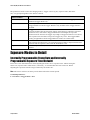
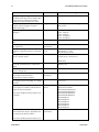
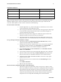
N u m ber of bits p er character u sed in the
serial p ort
Parity of the serial p ort
Data Size
N u m ber of stop bits p er character u sed
in the serial p ort
N u m ber of Stop
Bits
Parity
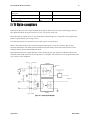
I / O Opto-couplers
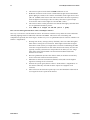
Falson2 p rovid es tw o sets of Op to-isolated inp u t signals. These can be u sed as external trigger sou rces.
The signals shou ld be in range from 2.4 V to 24 V, 5 V typ ical, 2 m A m in.
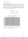
The d elay betw een signals at the I / O p in and the internal tim ing core is a fu nction of the signal sw ing
and the typ ical latency @ 5V sw ing is 6.5 µs.
N ote that the ou tp u ts are a p ow erless d evice and requ ire external p ow er.
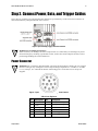
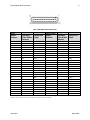
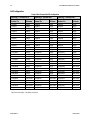
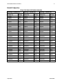
Refer to the 12-Pin H irose Pow er Connector signal d etails (p age 17) for the connector p in ou t and
electrical inform ation. The cable shell and shield shou ld electrically connect the cam era chassis to the
com p u ter chassis for m axim u m EMI p rotection.
Each inp u t incorp orates a signal d ebou nce circu it (follow ing the op to-cou p ler) to elim inate short noise
transitions that cou ld incorrectly be interp reted as a valid p u lse. The d u ration is u ser p rogram m able from
0 µs to 255 µs w ith Cam Exp ert.
Figure 14. I / O Optocoupler Diagram
Teledyne DALSA
03-032-20107-01