1
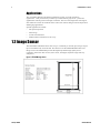
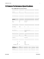
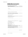
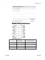
PANTERA 22M Camera User’s Manual Progressive Scan Monochrome Camera CA-40-22M03-00-L 20-Aug-11 www.teledynedalsa.com 03-032-20049-02 H H 2 PANTERA 22M User’s Manual About Teledyne Technologies and Teledyne D ALSA, Inc. Teled yne Technologies is a lead ing provid er of sophisticated electronic subsystem s, instrum entation and com m unication prod ucts, engineered system s, aerospace engines, and energy and pow er generation system s. Teled yne Technologies’ operations are prim arily located in the United States, the United Kingd om and Mexico. For m ore inform ation, visit Teled yne Technologies’ w ebsite at w ww .teled yne.com . Teled yne DALSA, a Teled yne Technologies com pany, is an international lead er in high performance d igital im aging and sem icond uctors w ith approxim ately 1,000 em ployees world w id e, headquartered in Waterloo, Ontario, Canada. Established in 1980, the com pany d esigns, d evelops, m anufactures and m arkets d igital im aging prod ucts and solutions, in add ition to provid ing MEMS prod ucts and services. For m ore inform ation, visit Teled yne DALSA’s website at ww w .teled yned alsa.com . Support For further inform ation not includ ed in this manual, or for inform ation on Teled yne DALSA’s extensive line of im age sensing prod ucts, please contact: North America Europe Asia Pacific 605 McMurray Rd Waterloo, ON N2V 2E9 Canad a Tel: 519 886 6000 Fax: 519 886 8023 w w w.teled ynedalsa.com Breslauer Str. 34 D-82194 Gröbenzell (Munich) Germ any Tel: +49 - 8142 – 46770 Fax: +49 - 8142 – 467746 w w w.teled ynedalsa.com Ikebukuro East 13F 3-4-3 H igashi-Ikebukuro Toshim a-ku, Tokyo 170-0013 Japan Tel: 81 3 5960 6353 Fax: 81 3 5960 6354 (fax) w w w.teled ynedalsa.com sales.am ericas@d alsa.com support@teled ynedalsa.com Teledyne DALSA sales.europe@teled ynedalsa.com support@teled ynedalsa.com sales.asia@teled yned alsa.com support@teled ynedalsa.com 03-032-20049-02 PANTERA 22M User’s Manual 3 Contents Introduction to the PANTERA 22M Area/TDI Scan Camera ____________________________ 5 1.1 Camera Highlights ....................................................................................................................................................... 5 1.2 Image Sensor ............................................................................................................................................................... 6 1.3 Camera Performance Specifications ............................................................................................................................ 7 1.4 Blemish specification ................................................................................................................................................... 9 Camera Hardware Interface ________________________________________________ 11 2.1 Installation Overview ................................................................................................................................................... 11 2.2 Input/Output Connectors and LED ............................................................................................................................... 11 Software Interface: How to Control the Camera __________________________________ 17 3.1 Communications Protocol Overview ............................................................................................................................ 17 3.2 Overview: Setting up the Camera to Send Commands ................................................................................................ 18 3.3 Saving and Restoring Settings ..................................................................................................................................... 19 3.4 Setting Operating Mode .............................................................................................................................................. 19 3.5 Setting Exposure Mode and Exposure Time (Area Mode) ........................................................................................... 19 3.6 TDI Mode ..................................................................................................................................................................... 24 3.7 Setting Sync Frequency (TDI and Area Mode) ............................................................................................................. 25 3.8 Switching between Area and TDI mode (TDI/Area Mode) .......................................................................................... 26 3.9 Setting the Camera Link Data Mode ........................................................................................................................... 26 3.10 Setting Baud Rate ...................................................................................................................................................... 27 3.11 Setting Gains ............................................................................................................................................................. 27 3.12 Monitoring the Camera ............................................................................................................................................. 29 3.13 Rebooting the Camera ............................................................................................................................................... 29 3.14 Setting the Video Mode and Generating Test Patterns ............................................................................................. 29 Optical and Mechanical Considerations ________________________________________ 31 4.1 Mechanical Interface .................................................................................................................................................... 31 4.2 Mounting the Camera .................................................................................................................................................. 32 4.3 Thermal Management ................................................................................................................................................. 32 4.4 Environment ................................................................................................................................................................ 32 Cleaning and Maintenance ________________________________________________ 33 5.1 Cleaning....................................................................................................................................................................... 33 5.2 Maintenance ................................................................................................................................................................ 35 Troubleshooting ________________________________________________________ 37 6.1 Common Solutions ....................................................................................................................................................... 37 6.2 Troubleshooting Using the Serial Interface ................................................................................................................. 38 6.3 Specific Solutions ......................................................................................................................................................... 39 6.4 Product Support ........................................................................................................................................................... 40 Teledyne DALSA 03-032-20049-02 4 PANTERA 22M User’s Manual Camera Link™ Reference, Configuration and Image Construction______________________ 41 Commands and Error Handling _____________________________________________ 45 Index _______________________________________________________________ 49 Revision History ________________________________________________________ 51 Teledyne DALSA 03-032-20049-02 PANTERA 22M User’s Manual 5 1 Introduction to the PANTERA 22M Area/TDI Scan Camera 1.1 Camera Highlights Features • 4008(H ) x 5344(V) resolu tion, fu ll fram e CCD architectu re • • • • • • • • • • The PAN TERA 22M offers u p to 3.6 fps, 4 ou tpu ts at fu ll resolu tion, 27 MH z d ata rate Up to 12 bit d igitization Sm all gain step s to achieve extrem ely low seam m ism at ch betw een taps H igh sensitivity w ith low d ark cu rrent Area or TDI m od e Exposu re control and antibloom ing Asynchronou s im age captu re, externally triggerable Tap to tap m atching 100% fill factor Single 12VDC pow er su pply Programmability • • Sim ple ASCII protocol controls gain, offset, fram e rates, trigger m od e, test pattern ou tpu t, and cam era d iagnostics Serial interface (ASCII, 9600 bau d , ad ju stable u p to 115200), throu gh Cam era Link™ Description The PAN TERA 22M d igital cam eras p rovid e high-sensitivity 12 bit im ages w ith a 4008 x 5344 sp atial resolu tion. The cam eras u se the fu ll fram e FTF4052M sensor to sim u ltaneou sly achieve ou tstand ing resolu tion and gray scale characteristics. A squ are pixel form at and high fill factor provid e su perior, qu antifiable im age qu ality even at low light levels. Teledyne DALSA 03-032-20049-02 6 PANTERA 22M User’s Manual Applications The PAN TERA 22M are ou tstand ing perform ers in fast, very high resolu tion ap plications. 12 bit perform ance provid es u p to 4096 d istinct gray levels—perfect for ap plications w ith large interscene light variations. The low -noise, d igitized vid eo signal also m akes the cam era an excellent choice w here low contrast im ages m u st be captu red in challenging ap plications. Specific applications inclu d e: • Flat panel inspection • Microscopy • Aerial reconnaissance • Med ical and non-d estru ctive test x-ray 1.2 Image Sensor The PAN TERA 22M offers fram e rates at u p to 3.6 fram es per second (fp s) u sing 4 ou tp u t tap s to sim u ltaneou sly read ou t d ata. This cam era u ses the FTF4052M fu ll-fram e CCD im age sensor. The FTF4052M provid es the highest possible im age qu ality for its resolu tion, w ith low er d ark cu rrent, low er noise, and higher d ynam ic range than any com petitor. Figure 1: FTF4052M Image Sensor Teledyne DALSA 03-032-20049-02 PANTERA 22M User’s Manual 7 1.3 Camera Performance Specifications Table 1: PANTERA 22M Camera Performance Specifications Camera Features Units Resolution H x V pixels 4008 x 5344 Pixel Size µm 9x9 Pixel Fill Factor % 100 Output taps Notes 4 Mechanical Interface Units Size mm 78 x 78 x 70 Weight kg 0.65 ± 5% Electrical Interface Units Pow er Dissipation W < 10 Input Voltage VDC 12 Pow er Connector Data Outpu t Form at Notes 15 6 pin H irose Bits 12/ 10/ 8 Base Cam era Link™ MDR26 Data Connector Optical Interface Notes Units Notes Back Focal Distance mm Lens Mount Aperture N ot present mm 36.072x48.096 µm º µm ±350 ±500 ±1.25 <900 over sensor Sensor Flatness µm 40 peak-peak Camera Performance Units Fram e Rate fps Data Rate MH z Sensor Alignm ent x, y z z Parallelism / Tilt Data Form at Teledyne DALSA 4.5±0.5 Min. Nom. Max. Notes 3.6 4x27 8, 10, or 12 bit user selectable 03-032-20049-02 8 PANTERA 22M User’s Manual At front plate Operating Tem p °C -10 50 Gain Range dB 0 24 Dynam ic Range dB 63 Pixel Response N on Uniform ity (PRN U) DN rm s 5 Fixed Pattern N oise (FPN ) DN rm s 3 Sat. Output Am plitud e DN 3680 3840 4000 1 DC Offset DN 80 160 240 1 >100x 1 21 12-bit @530nm Antibloom ing 2 Responsivity DN / (nJ/ cm ) Pow er Up Duration sec 10 Pow er Up Stabilization tim e m in 30 P P 19 20 Regulatory Regulatory Com pliance N one Notes: 1. N om inal ou tpu t, 100m s exp osu re tim e. Light sou rce: broad band qu artz halogen, 3200K, 750nm and IR cu toff filter. Figure 2 PANTERA 22M Spectral Responsivity Teledyne DALSA 03-032-20049-02 PANTERA 22M User’s Manual 9 1.4 Blemish specification PAN TERA 22M cam era inclu d es an FTF4052M CCD im age sensor, ind u strial grad e. Blem ish specification is presented below . Below table show s FTF4052M Sensor Blem ish Specifications, m axim u m nu m ber of blem ishes perm itted . Description IG (ind u strial grad e) Pixel d efects 100 Clu ster d efects 12 Spot d efects 0 Colu m n d efects 1 Row d efects 0 Definition of blem ishes Pixel defect Pixel w hose signal, at nom inal light (illu m ination at 50% of the linear range), d eviates m ore than ±30% from its neighbou ring pixels. Pixel w hose signal, in d ark, d eviates m ore than 250m V from its neighbou ring pixels. Cluster defect A grou ping of at m ost 5 pixel d efects w ithin a su b-area of 3*3 pixels. Spot defect A grou ping of m ore than 5 p ixel d efects w ithin a su b -area of 3*3 pixels. Column defect A colu m n w hich has m ore than 8 pixel d efects in a 1*12 kernel. Colu m n d efects m u st be horizontally sep arated by 3 good colu m ns. Row defect A horizontal grou ping of m ore than 8 pixel d efects betw een at least 2 good pixels on both sid es, w here single good pixels betw een 2 d efective pixels are consid ered as d efective. Test conditions Tem peratu re: 60°C Integration Tim e: 100m s Teledyne DALSA 03-032-20049-02 10 Teledyne DALSA PANTERA 22M User’s Manual 03-032-20049-02 PANTERA 22M User’s Manual 11 2 Camera Hardware Interface 2.1 Installation Overview In ord er to set u p you r cam era, you shou ld take these initial step s: This installation overview assumes you have not installed any system components yet. 1. Pow er d ow n all equ ipm ent. 2. Follow ing the m anu factu rer’s instru ctions, install the fram e grabber (if ap plicable). Be sure to observe all static precautions 3. Install any necessary im aging softw are. 4. Before connecting pow er to the cam era, test all pow er su p plies. Ensure that all the correct voltages are present at the camera end of the power cable (The Cam era Perform ance Specifications on page 6 list approp riate voltages). Pow er su pp lies m u st m eet the requ irem ents d efined in 2.2.3 Pow er Connector Pow er Inp u t. T T T HT TH 5. Inspect all cables and connectors p rior to installation. Do not u se d am aged cables or connectors or the cam era m ay be d am aged . 6. Connect d ata, serial interface, and pow er cables. 7. After connecting cables, app ly pow er to the cam era. After a few second s, the LED on the back of the cam era shou ld be green to ind icate that the cam era is operating and read y to receive com m and s. 2.2 Input/Output Connectors and LED The cam era u ses a: • • • Teledyne DALSA Diagnostic LED for m onitoring the cam era. See LED Statu s Ind icator section below for d etails. H igh-d ensity 26-pin MDR26 connector for Cam era Link control signals, d ata signals, and serial com m u nications. Refer to Figu re 4: MDR26 Connector for pin d escriptions. 6-pin H irose connector for p ow er. Refer to 2.2.3 Pow er Connector for pin d escriptions. HT TH 03-032-20049-02 12 PANTERA 22M User’s Manual Figure 3: Camera Inputs/Outputs 2.2.1 LED Status Indicator Please refer to section 3.12 Monitoring the Cam era , page 24 for d etail. HT TH T TH 2.2.2 Camera Link Data Connector The Cam era Link interface is im plem ented as a Base Configu ration in the PAN TERA 22M cam eras. A Base Configu ration u ses 1 MDR26 connector and 1 Channel Link chip. The m ain characteristics of the Base Configu ration are: • • • • Ports su p ported : A, B, C Serializer bit w id th: 28 N u m ber of chips: 1 N u m ber of MDR26 connectors: 1 Data Connector Figure 4: MDR26 Connector Teledyne DALSA 03-032-20049-02 PANTERA 22M User’s Manual 13 Table 2: MDR26 Connector Reference Item Value Pinout BASE 1 2 3 4 5 6 7 8 9 10 11 12 13 GN D X0X1X2XclkX3SERTC+ SERTFGCC1CC2+ CC3CC4+ GN D Item Pinout Value BASE 14 15 16 17 18 19 20 21 22 23 24 25 26 GN D X0+ X1+ X2+ Xclk+ X3+ SERTCSERTFG+ CC1+ CC2CC3+ CC4GN D Notes: T *Exterior Overshield is connected to the shells of the connectors on both end s. **3M part 14X26-SZLB-XXX-0LC is a com plete cable assem bly, includ ing connectors. Unused pairs should be term inated in 100 ohm s at both end s of the cable. Table 3: Camera Control Configuration Signal Configuration CC1 CC2 CC3 CC4 Sm art EXSYN C(Area Mod e) Line Sync (TDI m od e) Area/ TDI m od e Spare Digital Data The cam era d igitizes internally to 12 bits and has a u ser selectable ou tpu t of 8, 10, or 12 bits in LVDS form at on the Cam era Link connector. You can select the ou tpu t u sing the clm com m and . For d etails, see section 3.9 Setting the Cam era Link Data Mod e. Data Clocking Signals These signals ind icate w hen d ata is valid , allow ing you to clock the d ata from the cam era to you r acqu isition system . These signals are p art of the Cam era Link configu ration and you shou ld refer to the Teled yne DALSA Cam era Link Im plem entation Road Map, available w ith contacting Teled yne DALSA Technical su p port, for the stand ard location of these signals: IMPORTANT: This camera’s data should be sampled on the rising edge of STROBE. Teledyne DALSA Clocking Signal Indicates LVAL (high) DVAL (high) STROBE (rising edge) FVAL (high) Outputting valid line Valid d ata Valid d ata Outputting valid fram e 03-032-20049-02 14 PANTERA 22M User’s Manual See Ap pend ix A for the com plete Cam era Link tim ing, Teled yne DALSA Cam era Link configu ration table, and contact Teled yne DALSA Technical su p port, for the official Cam era Link d ocu m ent. Input Signals The cam era accepts an EXSYN C control inpu t throu gh the Cam era Link MDR26F connector. EXSYNC (Triggers Readout) For high speed com m u nication the CC lines of cam era link w ill be u sed . The table below show s high speed controls: Table 4: PANTERA 22M Camera Control Configuration Camera Link Function input CC1 Smart ExSync (Frame trigger and exposure control) CC2 Line sync CC3 0 - Area mode, split vertical transfer. 1 - TDI mode, one-way transfer Note Will be ignored in TDI mode TDI mode only The direction of one-way transfer is set by software 2.2.3 Power Connector Pin Description Pin Description 1 +12V 4 GN D 2 +12V 5 GN D 3 +12V 6 GN D The cam era requ ires a single voltage inpu t (+12VDC to +15VDC). The cam era m eets all perform ance specifications u sing stand ard sw itching pow er su pplies, althou gh w ell regu lated linear su p plies provid e optim u m perform ance. When setting u p the cam era’s pow er su p plies follow these gu id elines: • • • Protect the cam era w ith a fast-blow fu se betw een pow er su pply and cam era. Do not u se the shield on a m u lti-cond u ctor cable for grou nd . Keep lead s as short as possible to red u ce voltage d rop. • Use high-qu ality linear su pplies to m inim ize noise. Note: Perform ance specifications are not gu aranteed if you r pow er su pply d oes not m eet these requ irem ents Teledyne DALSA 03-032-20049-02 PANTERA 22M User’s Manual 15 WARNING: It is extremely important that you apply the appropriate voltages to your camera. Incorrect voltages will damage the camera. Protect the camera with a fast-blow fuse between power supply and camera. Visit the w w w .teled yned alsa.com Web site for a list of com panies that m ake p ow er su pp lies that m eet the cam era’s requ irem ents. The com panies listed shou ld not be consid ered the only choices. Teledyne DALSA 03-032-20049-02 16 Teledyne DALSA PANTERA 22M User’s Manual 03-032-20049-02 PANTERA 22M User’s Manual 17 3 Software Interface: How to Control the Camera All cam era featu res can be controlled throu gh the serial interface. The cam era can also be u sed w ithou t the serial interface after it has been set u p correctly. This chapter explains the m ost com m only u sed and im portant com m and s, inclu d ing: 3.3 Saving and Restoring Settings 3.4 Setting Operating Mod e 3.5 Setting Exposu re Mod e and Exposu re Tim e (Area Mod e) 3.6 Setting Scan Direction and Sync Mod e (TDI Mod e) 3.7 Setting Sync Frequ ency (TDI and Area Mod e) 3.8 Sw itching betw een area and TDI m od e (TDI/ Area Mod e) 3.9 Setting the Cam era Link Data Mod e 3.10 Setting Bau d Rate 3.11 Setting Gains 3.12 Monitoring the Cam era 3.13 Rebooting the Cam era 3.14 Setting the Vid eo Mod e and Generating Test Patterns i HT TH HT This chapter outlines the more commonly used commands. See Appendix B for a list of all available commands. TH HT TH HT TH HT TH HT HT TH TH HT TH HT TH HT TH HT TH HT TH The serial interface u ses a sim ple ASCII-based protocol. For a com plete list of all available com m and s, refer to the Com m u nications Protocol on p age C om m and s and Error H and ling . HT TH Online Help For qu ick help, the cam era can retu rn all available com m and s and param eters throu gh the serial interface. To generate this list, send the com m and h to the cam era. T T Retrieving Camera Settings To read cu rrent cam era settings, send the com m and gcp. 3.1 Communications Protocol Overview Serial Protocol Defaults: • Teledyne DALSA 8 d ata bits 03-032-20049-02 18 PANTERA 22M User’s Manual • • • • • 1 stop bit N o parity N o flow control 9.6Kbps Cam era d oes not echo characters When entering commands, remember that: • • • A carriage retu rn (CR) end s each com m and . The linefeed character is ignored . The cam era w ill answ er each com m and w ith either "OK >" or "Error x: Error Message >". The ">" is alw ays the last character sent by the cam era. The follow ing param eters are u sed throu ghou t the m anu al: i = integer f = float t = tap [ ] = optional param eter 3.2 Overview: Setting up the Camera to Send Commands The follow ing step s d escribe how to begin u sing the PAN TERA 22M and com m and s. 1. If you have not alread y set u p you r cam era cables, connect you r cables as d escribed in section 2.1 Installation Overview . Using a term inal program (e.g., Microsoft H yperTerm inal), open a term inal w ind ow . HT 2. TH Note: In ord er to com m u nicate w ith the cam era, a serial connection in the Cam era Link cable need s to be established . The fram egrabber m anu factu rers shou ld be able to provid e a solu tion in ord er to com m u nicate throu gh this serial link. The term inal softw are can be also p rovid ed by the fram egrabber m anu factu rer. Stand ard term inal softw are su ch as H yperTerm inal can be u sed in case if COM port is allocated by the fram egrabber. Term inal shou ld be set at 9600 bau d d u ring the cam era p ow er u p. 3. When the term inal w ind ow is set u p, pow er on the cam era. 4. The boot-u p m essage shou ld ap pear on the term inal w ind ow : Configuration Successful. OK> You can now com m u nicate w ith the cam era throu gh the term inal u sing the softw are com m and s d escribed in this m anu al. 5. 6. 7. Teledyne DALSA Set u p the fram egrabber to receive the d ata. Follow ing the fram egrabber m anu factu rer’s instru ctions, set u p the param eters d escribed in the Cam era Link™ Configu ration Table on page 42. Once the fram egrabber is set u p for d ata processing and the cam era is pow ered u p, ru n you r im age processing softw are. You shou ld b e able to see an im age from the cam era w hen exp osed to a light sou rce. You can now set the other cam era p aram eters d escribed in this chapter. 03-032-20049-02 PANTERA 22M User’s Manual 19 3.3 Saving and Restoring Settings The cam era provid es a nu m ber of com m and s for restoring, storing, and saving settings. • • • To restore the original factory settings, u se the com m and rfs. To save all cu rrent u ser settings to EEPROM, u se the com m and wus. The cam era w ill au tom atically restore the saved u ser setting s w hen p ow ered u p. To restore the last saved u ser settings, u se the com m and rus. T T T T T T Figure 5: Saving and Restoring Overview Factory Settings restore rfs command User Settings / EEROM write / restore wus, rus commands Current Session 3.4 Setting Operating Mode To select camera’s operating mode, use the command: Syntax: tdi i Syntax Elem ents: i 0 Area/ TDI m od e (Selectable by CC3) 1 Sm art ExSync (Area Mod e) 2 Line Sync (TDI m od e) Related Com m and s: Exam ple: tdi 1 3.5 Setting Exposure Mode and Exposure Time (Area Mode) With three d ifferent exposu re m od e settings, the PAN TERA 22Mcam eras d eliver m any possibilities for flexible cam era tim ing. Table ou tlines each of these three exposu re m od es, and is follow ed by a fu ll explanation on how to set the cam era’s fram e rate and exp osu re tim e. Teledyne DALSA 03-032-20049-02 20 PANTERA 22M User’s Manual Mode Table5: Overview of PANTERA 22M Exposure Modes i SYNC Exposure Time 0 –External 1 –Internal -Program m able –Fram e rate is internally set to correspond w ith the program m ed exposure tim e plus read out tim e. –External –N ot program m able –Exposure tim e is set by the high pulse w id th of the iCC1 signal. For more information on the EXSYNC signal, refer to section 2.2 Input/Output Connectors and LED. 2 Notes –Internal –Program m able using the set com m and - Program m able using the ssf com m and -Program m able w ith set com m and ―Sm art EXSYN C‖ Mod e: external exposure tim e – high tim e of external signal is exposure tim e and 1/ period is fram e rate. The rising ed ge of iCC1 begins cam era exposure. The falling ed ge begins read out. Fact ory Default Mode. Fram e period is the program m ed exposure tim e plus the read out tim e. The fram e period can be read in this m od e by using the gcp com m and . The user is responsible for not violating tim ing constraints for the EXSYN C signal used in this m od e. The falling ed ge of EXSYN C initiates the fram e transfer. i Mode 1 is the factory setting Overview: Setting Exposure mode and Exposure Time The cam era’s fram e rate (synchronization) can be generated internally throu gh softw are com m and s or inpu t externally from a fram e grabber/ host system . To select how you w ant the cam era’s fram e rate to be generated : 1. You m u st first set the cam era m od e u sing the sem com m and . Refer to Step One on the follow ing for d etails. 2. Then, if you are u sing m od e 1, u se the set com m and to set the exposu re tim e. Refer to Step Tw o in 3.5.2 for d etails. Then u se the ssf t o set the fram e rate. Refer to 3.7 Setting Sync Frequ ency (TDI and Area Mod e) . T T T T HT TH 3.5.1 Step 1: Setting the Exposure Mode In internal sync m od e, (m od e 1), the cam era d elivers d ata ind epend ent of external signals accord ing to the tim ing set internally. In external sync m od es (m od es 2), the cam era starts exposu re after an external trigger pu lse (iCC1). To select camera’s exposure mode, use the command: Teledyne DALSA Syntax: sem i Syntax Elem ents: i 03-032-20049-02 PANTERA 22M User’s Manual 21 0 Sm art ExSync (Area Mod e) 1 Fram e Sync Internal, Exposure Internal 2 Fram e Sync External, Exposure Internal N otes: To obtain the current value of the exposure m od e, use the com m and gcp. T Related Com m and s: set Exam ple: sem 1 T Mode 0: Smart EXSYNC, External Frame Rate and Exposure Time Figure5. Area mode timing diagram The below table show s ou r recom m end ed tim ing valu es, Teledyne DALSA Tim ing Type Recom m end ed valu e Rem arks T1 Variable >276 m s Fram e period , m axim u m fram e rate = 3.6 fram es/ sec T2 Variable 10 u s + exposu re tim e iCC1 high length T3 Typical 718.8 u s iCC1 falling ed ge to FVAL start T4 Typical 275.3 m s FVAL length for one fram e 03-032-20049-02 22 PANTERA 22M User’s Manual T5 Typical 27 u s FVAL start to LVAL start T6 Typical 74.22 u s LVAL length T7 Typical 28.75 u s LVAL end to next line LVAL start T8 Variable >1 m s Id le tim e, d epend ing on fram e rate and exposu re tim e In Sm art Exsync m od e, the follow ing events take place: Rising ed ge of iCC1 Fram e Sync pu lse is triggering charge d u m p(CD) Charge d u m p tim e w hich is fixed and set internally to 10µs After charge d u m p, exposu re begins and lasts till iCC1 falling ed ge. the iCC1 falling ed ge cau ses fram e transfer inclu d ing vertical and horizontal read ou ts to begin. The first 6 lines of read ou t are d u m m y lines The next 2672 lines are active lines w ith vid eo d ata At the end of the fram e transfer the cam era goes into id le operation state and rem ains in this state u ntil a next iCC1 rising ed ge. The d u ration of iCC1 pu lse in high state shou ld be larger than Charge reset tim e. The fram e period shou ld be larger than the su m of charge d u m p tim e, exposu re tim e, and the fram e transfer tim e (inclu d ing d u m m y and active lines). The iCC3 signal shou ld be d riven LOW d u ring area m od e operation of the cam era. Mode 1: Internal Frame Sync and Internal Exposure Time In this m od e, the exposu re tim e is program m ed internally w ith the set com m and (d escribed on follow ing p age); the fram e rate is program m ed internally w ith ssf com m and (d escribed on follow ing page). The Read ou t occu rs im m ed iately after the exposu re tim e. After the read ou t is com plete, the next exposu re begins again. Both fram e sync and exposu re tim es are generated internally. The sam e restrictions as in m od e 0 ap ply to this m od e. Teledyne DALSA 03-032-20049-02 PANTERA 22M User’s Manual 23 Mode 2: External Frame Sync and Internal Exposure Time In this m od e, iCC1 sets the fram e rate bu t the exposu re tim e is set internally u sing the softw are com m and , set (d escribed on follow ing page). A new fram e starts w ith iCC1 rising ed ge, then rest of processes are d one internally, bu t id entically to m od e 0 The below table show s ou r recom m end ed tim ing valu es, Tim ing Type Recom m end ed valu e Rem arks T1 Variable >276 m s Fram e period , m axim u m fram e rate = 3.6 fram es/ sec T2 Fixed by u ser 100 u s iCC1 high length. N ot critical as iCC1 falling ed ge d oesn’t trigger any action 3.5.2 Step 2: Setting Exposure Time Setting Exposure Time Cam era m u st be operating in exposu re m od e 1, 2. To set the camera exposure time, use the command: Syntax: set i Syntax Elem ents: i Floating point num ber in m illisecond s. Allow able range is 110,000,000 m icrosecond s. N otes: Teledyne DALSA To read the current line rate frequency, use the com m and gcp. If you enter an invalid exposure tim e, the valid range of values w ill be d isplayed . T Related Com m and s: sem, ssf Exam ple: set 100,000 T T 03-032-20049-02 24 PANTERA 22M User’s Manual 3.6 TDI Mode In TDI m od e, the follow ing events take place: Rising ed ge of iCC2 Line Sync pu lse or internal cou nter is triggering beginning of a new line N ew line starts w ith vertical transfer of one line Stop vertical transfer and start horizontal read ou t Read ou t d u m m y pixels Read ou t active lines. In parallel process d ata from active pixels. Enable LVAL for active pixels d ata. Overclock pixels, requ ired for internal p rocessing Id le state, w aiting for next line sync Figure 2. TDI mode timing diagram The below table show s ou r recom m end ed tim ing valu es, Tim ing Type Recom m end ed valu e Rem arks T1 Typical 103u s Line period , set externally or internally Equ ivalent to 9.71kH z line rate T2 Minim u m 0.12-1 u s iCC2 high length. N ot critical as iCC2 falling ed ge d oesn’t trigger any action Teledyne DALSA T3 Typical 28.7 u s Line Sync to LVAL start T4 Typical 74.22 u s LVAL, slightly d elayed from active pixels d u e to internal d ata processing 03-032-20049-02 PANTERA 22M User’s Manual 25 T5 Variable 1 us Depend ing on line rate If iCC2 (line sync) is ru nning at higher rate than the m axim u m , the signal w ill be ignored . When the cam era operates in TDI m od e, iCC3 is d riven H igh and iCC1 valu e is ignored (so iCC1 cou ld be d riven either LOW – recom m end ed , or H igh). The sensor is exposed all the tim e and the lines are read w ith the frequ ency of the iCC2. The valu e of FVAL w ill be set to LOW. Setting TDI Direction (scd) To set CCD scanning direction in TDI mode, use the command: Syntax: scd i Syntax Elem ents: i 0 Top to bottom 1 Bottom to top Related Com m and s: tdi Exam ple: Scd 0 Setting Sync Mode (ssm) To set sync mode to internal or external in TDI mode, use the command: Syntax: ssm i Syntax Elem ents: i 0 Internal Line sync 1 External line sync Related Com m and s: tdi Exam ple: ssm 1 3.7 Setting Sync Frequency (TDI and Area Mode) For both TDI and Area mode, to set the camera’s frame rate and line rate values, use the command: Teledyne DALSA Syntax: ssf i i Syntax Elem ents: i 1 Fram e rate: 278 – 16383 m illisecond s 2 Line rate: 2780 – 16383 counts of pixel clock 03-032-20049-02 26 PANTERA 22M User’s Manual N otes: To read the current line rate frequency, use the com m and gcp. If you enter an invalid fram e rate or line rate, the valid range of values w ill be d isplayed. Related Com m and s: sem, ssm Exam ple: ssf 1 2780 3.8 Switching between Area and TDI mode (TDI/Area Mode) 1. TDI m od e to Area It is safe to sw itch from TDI m od e to Area m od e. 2. Area m od e to TDI m od e It is safe to sw itch d u ring exposu re tim e or id le tim e. If sw itched d u ring fram e transfer, the read ou t of fu ll fram e w ill be d one first before the cam era enters into TDI m od e. 3.9 Setting the Camera Link Data Mode The PAN TERA 22M cam era Cam eraLink p ort has tw o taps (channels), each are 12 bits. The 24 bits of d ata that are sent from the cam era to the fram e grabber are d ivid ed into three ports: A, B, C. Each port is 8 bits. The clm com m and selects the nu m ber of bits that the cam era send s to the fram e grabber from each tap. In the table below , ports A -C refer to the cam era link specification. To select the bit resolution for data sent via the CameraLink interface, use the command: Syntax: clm i Syntax Elem ents: i 0 1 2 Teledyne DALSA N otes: Exam ple: clm 0 12 bit (Factory setting), Tap 1 Data bits 0 to 7 are linked to Port A Tap 1Data bits 8 to 11 are linked to Port B bits 0 to 3 Tap 2 Data bits 8 to 11 are linked to Port B bits 4 to 7 Tap 2 Data bits 0 to 7 are linked to Port C 10 bit, Tap 1 Data bits 0 to 7 are linked to Port A Tap 1 Data bits 8 and 9 are linked to Port B bits 0 and 1 Tap 2 Data bits 8 and 9 are linked to Port B bits 4 and 5 Tap 2 Data bits 0 to 7 are linked to Port C 8 bit, Tap 1 Data bits 0 to 7 are linked to Port A Tap 2 Data bits 0 to 7 are linked to Port B To obtain the current output d ata form at, use the com m and gcp 03-032-20049-02 PANTERA 22M User’s Manual 27 3.10 Setting Baud Rate Change speed of cam era serial com m u nication port. Defau lt speed of com m u nication after p ow er-on cycle is alw ays 9600 bau d . Param eters of serial com m u nication are as follow s: Eight (8) d ata bits N o (N ) parity One (1) stop bit N o hard w are flow control To set the speed of the camera serial communication port, use the command: Syntax: sbr i Syntax Elem ents: i Baud rate. Available baud rates are: 9600 (Default), 14400, 19200, 28800, and 115200. N otes: Exam ple: Pow er-on rate is alw ays 9600 baud . The rc (reset cam era) com m and w ill not reset the cam era to the pow er-on baud rate. sbr 9600 3.11 Setting Gains Optim izing gain in the analog d om ain allow s you to achieve a better signal-to-noise ratio (d ynam ic range). As a resu lt, perform all analog gain ad ju stm ents w ith sag and sg com m and . Setting Analog Gain for Tap to Tap Matching The set analog gain com m and allow s you to ad ju st the analog gain in fou r channels for precise control over tap -to-tap m atching. This valu e is d irectly w ritten to the vid eo processor and d oes not take into accou nt the 0d B gain reference. Cu rrent valu e of analog again m ay be obtained fr om gcp ou tpu ts. Since taps that have been m od ified w ith the sag com m and d o not allow for d B gain reference, these valu es w ill not be d isplayed by gcp ou tpu ts. Gain valu es entered by w ay of the sag com m and are not saved w ith u ser settings. If sag is changed , then the m ap ping shou ld be u pd ated by ugr com m and . If this is not d one, d B valu e cou ld get ou tsid e of allow ed range. sag com m and is m ostly u sed for responsivity and tap m atching calibration at factory. To set the analog gain, u se the com m and : Syntax: sag t i Syntax Elem ents: t 0 Teledyne DALSA - all taps 03-032-20049-02 28 PANTERA 22M User’s Manual 1-4 - Tap count (select single tap) i 0-1023. 0 correspond s to low gain, 1023 correspond s to high gain Related Com m and s: gag ; ugr Exam ple: sag 0 27 Update Gain Reference Com m and ugr is to u pd ate 0d B gain reference to be equ al to the cu rrent valu e of analog gain setting. It is the DN valu e cu rrently set to the vid eo processor’s gain registers that is u sed as the gain reference. As su ch, valu es entered via the sag com m and ) as w ell as the sg com m and are equ ally ap plicable. Gain references are saved w ith u ser settings. Syntax: ugr Set Gain (sg) Com m and sg is for setting analog gain in the vid eo p rocessor. The valu e w ritten to the vid eo processor is su m m ed w ith the 0d B gain refer ence. Cu rrent valu e of analog gain m ay be obtained from gcp, and gag ou tpu ts. Gain settings entered by w ay of the sg com m and are saved w ith u ser settings. If ju st higher resp onsivity is need ed on all taps, the easiest w ay is to send a com m and sg 0 x. To set the analog gain, u se the com m and : Syntax: sg t i Syntax Elem ents: t 0 - all taps 1-4 - Tap count (select single tap) i 0.0 – 24.0 in d B, 0 correspond s to low gain, 24 correspond s to high gain Teledyne DALSA Related Com m and s: gag ; gcp Exam ple: Sg 0 0 03-032-20049-02 PANTERA 22M User’s Manual 29 3.12 Monitoring the Camera Note: When more than one condition is active, the LED indicates the condition with the highest priority. Error and warning states are accompanied by corresponding messages further describing the current camera status. The cam era is equ ipped w ith a red / green LED u sed to d isplay the operational statu s of the cam era. Table 6 below su m m arizes the operating states of the cam era and the correspond ing LED states. Table 6: Camera Operating States LED state Priority Blinking RED Stead y RED Blinking GREEN Stead y GREEN Camera Status Condition 1 2 3 Error Warning Progress Fatal hard w are failure Monitoring task failure Lengthy operation in progress 4 OK H ealthy 3.13 Rebooting the Camera The com m and rc reboots the cam era. The cam era starts u p w ith the last saved settings. 3.14 Setting the Video Mode and Generating Test Patterns To set the video mode, use the command: Syntax: tps i Syntax Elem ents: i Exam ple: Teledyne DALSA 0 vid eo 1 Test pattern 1 2 Test pattern 2 tps 0 03-032-20049-02 30 Teledyne DALSA PANTERA 22M User’s Manual 03-032-20049-02 PANTERA 22M User’s Manual 31 4 Optical and Mechanical Considerations 4.1 Mechanical Interface Figure 6: Mechanical Drawing Teledyne DALSA 03-032-20049-02 32 PANTERA 22M User’s Manual 4.2 Mounting the Camera The PAN TERA 22Mcam eras can be m ou nted via the 4 holes. 4.3 Thermal Management For any CCD cam era optim al perform ance is achieved by transferring heat aw ay from the sensor. Keeping a sensor ―cool‖ red u ces the am ou nt of d ark cu rrent generated . Dark cu rrent is the lead ing contribu tor to FPN , PRN U, d ark offset, rand om noise and other perform ance specifications, especially w hen a cam era is significantly gained (i.e. +10d b). PAN TERA 22M m echanicals have been optim ized to transfer heat from the sensor to the front of the hou sing. Recom m end to m ou nt cam era on a m etal plate. Mou nt fans aw ay from the cam era to avoid vibration, and d irect the airflow across the hou sing to d ecrease the tem peratu re d elta betw een am bient and hou sing tem peratu res. Proper installation greatly red u ces d ark cu rrent and w ill im p rove you system s perform ance. 4.4 Environment The cam era and cables shou ld be shield ed from environm ental noise sou rces for best operation. The cam era shou ld also be kept as cool as possible. The specified operating tem peratu re is -10–50°C m easu red at the front su rface of the cam era. Teledyne DALSA 03-032-20049-02 PANTERA 22M User’s Manual 33 5 Cleaning and Maintenance 5.1 Cleaning Electrostatic Discharge and the CCD Sensor Charge-cou pled d evice (CCD) im age sensors are m etal oxid e sem icond u ctor (MOS) d evices and are su sceptible to d am age from electrostatic d ischarge (ESD). Althou gh m any sensor pins have ESD protection circu itry, the ESD p rotection circu itry in CCDs is typically not as effective as those fou nd in stand ard CMOS circu its. Electrostatic charge introd u ced to the sensor w ind ow su rface can ind u ce charge bu ild u p on the u nd ersid e of the w ind ow that cannot be read ily d issip ated by the d ry nitrogen gas in the sensor package cavity. When charge bu ild u p occu rs, su rface gated photod iod es (SGPDs) m ay exhibit higher im age lag. Som e SGPD sensors m ay also exhibit a highly non-u niform response w hen affected by charge bu ild -u p, w ith som e pixels d isplaying a m u ch higher response w hen the sensor is exposed to u niform illu m ination. The charge norm ally d issip ates w ithin 24 hou rs and the sensor retu rns to norm al operation. Preventing ESD Damage To prevent ESD d am age, w e ad vise you to take the follow ing hand ling precau tions. 1. Grou nd you rself p rior to hand ling CCDs. 2. Ensu re that you r grou nd and you r w orkbench are also properly grou nd ed . Install cond u ctive m ats if you r grou nd or w orkbench is non -cond u ctive. 3. Use bare hand s or non -chargeable cotton gloves to hand le CCDs. N OTE: Ru bber fingercots can introd u ce electrostatic charge if the ru bber com es in contact w ith the sensor w ind ow . 4. Do not tou ch the w ind ow , especially in the region over the im aging are a. 5. Grou nd all tools and m echanical com p onents that com e in contact w ith the CCD. 6. We recom m end that CCDs be hand led u nd er ionized air to prevent static charge bu ild u p. The above ESD precau tions need to be follow ed at all tim es, even w hen there is no evid ence of CCD d am age. The rate w hich electrostatic charge d issipates d epend s on nu m erou s environm ental cond itions and an im proper hand ling proced u re that d oes Teledyne DALSA 03-032-20049-02 34 PANTERA 22M User’s Manual not ap pear to be d am aging the CCDs im m ed iately m ay cau se d am age w ith a change in environm ental cond itions. Protecting Against Dust, Oil, and Scratches The CCD w ind ow is p art of the optical path and shou ld be hand led like other optical com ponents, w ith extrem e care. Du st can obscu re pixels, p rod u cing d ark patches on the sensor response. Du st is m ost visible w hen the illu m ination is collim ated . The d ark patches shift position as the angle of illu m ination changes. Du st is norm ally not visible w hen the sensor is positioned at the exit port of an integrating sp here, w here the illu m ination is d iffu se. Du st can norm ally be rem oved by blow ing the w ind ow su rface u sing an ionized air gu n. Oil is u su ally introd u ced d u ring hand ling. Tou ching the su rface of the w ind ow barehand ed w ill leave oily resid u es. Using ru bber fingercots and ru bber gloves can prevent contam ination . H ow ever, the friction betw een rubber and the w ind ow m ay prod u ce electrostatic charge that m ay d am age the sensor. To avoid ESD d am age and to avoid introd u cing oily resid u es, avoid tou ching the sensor. Scratches d iffract incid ent illu m ination. When exposed to u niform illu m ination, a sensor w ith a scratched w ind ow w ill norm ally have brighter p ixels ad jacent to d arker pixels. The location of these pixels w ill change w ith the angle of illu m ination. Cleaning the Sensor Window Equipment Required Glass cleaning station w ith m icroscope w ithin clean room . 3M ionized air gu n 980 (http:/ / solu tions.3m canad a.ca/ w p s/ p ortal/ 3M/ en_CA/ WW2/ Cou ntry/ ) Ionized air flood system , foot operated . Sw ab (H UBY-340CA-003) (http:/ / w w w .cleancross.net/ m od u les/ xfsection/ article.php?articleid =24) Single d rop bottle (FD-2-ESD) E2 (Eclip se optic cleaning system (w w w .photosol.com ) Procedure Teledyne DALSA Use localized ionized air flow on to the glass d u ring sensor cleaning. Blow off m obile contam ination u sing an ionized air gu n. Place the sensor u nd er the m icroscope at a m agnification of 5x to d eterm ine the location of any rem aining contam ination. Clean the contam ination on the sensor u sing one d rop of E2 on a sw ab. Wipe the sw ab from left to right ( or right to left bu t only in one d irection). Do this in an overlapping pattern, tu rning the sw ab after the first w ipe and w ith each su bsequ ent w ipe. Avoid sw iping back and forth w ith the sam e sw ab in ord er to ensu re that p articles are rem oved and not sim ply transferred to a new location on the sensor w ind ow . This p roced u re requ ires you to u se m u ltiple sw abs. Discard the sw ab after both sid es of the sw ab have been u sed once. Repeat u ntil there is no visible contam ination present. 03-032-20049-02 PANTERA 22M User’s Manual 35 5.2 Maintenance There are no u ser serviceable parts on this cam era. Please contact Teled yne DALSA for service. Teledyne DALSA 03-032-20049-02 36 Teledyne DALSA PANTERA 22M User’s Manual 03-032-20049-02 PANTERA 22M User’s Manual 37 6 Troubleshooting The inform ation in this chapter can help you solve problem s that m ay occu r d u ring the setu p of you r cam era. Rem em ber that the cam era is part of the entire acqu isition system . You m ay have to trou bleshoot any or all of the follow ing: pow er su pplies cabling fram e grabber hard w are & softw are host com pu ter light sou rces optics operating environm ent encod er You r steps in d ealing w ith a technical problem shou ld be: 1. Try the general and specific solu tions listed in sections 6.1, 6.2, and 6.3. 2. If these solu tions d o not resolve you r problem , see section 6.4 on getting prod u ct su pp ort. 6.1 Common Solutions Connections The first step in trou bleshooting is to verify that you r cam era has all the correct connections. Power Supply Voltages Check for the presence of all voltages at the cam era p ow er connector. Verify that all grou nd s are connected . EXSYNC When the cam era is pow ered on for the first tim e, the factory setting is d efau lt(no external inpu ts requ ired ). After you have saved settings, the cam era pow ers u p w ith the saved settings next tim e it is rebooted . Data Clocking/Output Signals To valid ate cable integrity, have the cam era send ou t a test pattern and verify it is being properly received . Teledyne DALSA 03-032-20049-02 38 PANTERA 22M User’s Manual 6.2 Troubleshooting Using the Serial Interface The follow ing com m and s can aid in d ebu gging. (The com plete com m and protocol is d escribed in Ap pend ix B.) Communications To qu ickly verify serial com m u nications send the help com m and . The h com m and retu rns the online help m enu . Verify Parameters To verify the cam era setu p, send the gcp com m and . Verify Factory Calibrated Settings To restore the cam era’s factory settings, send the rfs com m and . After execu ting this com m and send the gcp com m and to verify the factory settings. Verify Timing and Digital Video Path Use the test p attern featu re to verify the proper tim ing and connections betw een the cam era and the fram e grabber and verify the proper ou tp u t along the d igital processing chain. See below . Generating Test Patterns The cam era can generate a test pattern to aid in system d ebu gging. Use the com m and svm i to activate the test pattern (see section 3.14 Setting the Vid eo Mod e and Generating Test Patterns for d etails). The test p attern is a ram p from 1 to the nu m ber of pixels in the line, then starts at 1 again. Use the test pattern to verify the proper tim ing and connections betw een the cam era and the fram e grabber. N o test pattern or bad test pattern — May ind icate a problem w ith the cam era (e.g. m issing bit) or a system setu p problem (e.g. fram e grabber or tim ing). Verify the presence of the LVAL and STROBE signals. Test pattern successful — Ru n the svm 0 com m and to d eactivate vid eo correction. Verify Temperature To check the cam era’s internal tem peratu re, u se the vt com m and . If it is w ithin the proper range, the cam era retu rns OK>. Otherw ise the cam era retu rns an error m essage. LED Status Located on the back of the cam era is a red / green LED u sed to d isplay the operational statu s of the cam era. Red lights ind icate errors or w arnings and green lights ind icate progress and OKs. Error and w arning states are accom p anied by correspond ing m essages fu rther d escribing cu rrent cam era statu s. See section 2.2.1 LED Statu s Ind icator for the com plete LED inform ation. Teledyne DALSA 03-032-20049-02 PANTERA 22M User’s Manual 39 6.3 Specific Solutions No Output or Erratic Behavior If you r cam era provid es no ou tpu t or behaves erratically, it m ay be picking u p rand om noise from long cables acting as antennae. Do not attach w ires to u nu sed pins. Verify that the cam era is not receiving spu riou s inpu ts (e.g. EXSYN C, if cam era is in expo su re m od e that regu lates external signals). Line Dropout, Bright Lines, or Incorrect Frame Rate Verify that the frequ ency of the internal sync is set correctly, or w hen the cam era is set to external sync that the EXSYN C signal su pplied to the cam era d oes not exceed the cam era’s m axim u m specified fram e rate. Noisy Output Check you r pow er su pply voltage ou tpu ts for noise. N oise present on these lines can resu lt in poor vid eo qu ality. Low qu ality or non -tw isted pair cable can also ad d noise to the vid eo ou tpu t. Dark Patches If d ark p atches appear in you r ou tpu t the optics path m ay have becom e contam inated . Refer to the sensor cleaning proced u re in Chapter 5. for p roper cleaning instru ctions. Horizontal Lines or Patterns in Image A fau lty or irregu lar encod er signal m ay resu lt in horizontal lines d u e to exposu re tim e flu ctu ations; ensu re that you r exposu re tim e is regu lar. If you have verified that you r exposu re tim e is consistent and patterns of low frequ ency intensity variations still occu r, ensu re that you are u sing a DC or high frequ ency light sou rce. Teledyne DALSA 03-032-20049-02 40 PANTERA 22M User’s Manual 6.4 Product Support If there is a problem w ith you r cam era, collect the follow ing d ata abou t you r a p plication and situ ation and call you r Teled yne DALSA representative. Note: You m ay also w ant to photocopy this page to fax to Teled yne DALSA. Customer name Organization name Customer phone number fax number Complete Product Model Number (PT-21-11M04, PT-21-06M08...) Complete Serial Number Your DALSA Agent or Dealer Acquisition System hardware (frame grabber, host computer, light sources, etc.) Acquisition System software (version, OS, etc.) Power supplies and current draw Data rate used Control signals used in your application, and their frequency or state (if applicable) Results when you run the gcp command Detailed description of problem encountered. EXSYNC Other _______ please attach description with as much detail as appropriate In ad d ition to you r local Teled yne DALSA representative, you m ay need to call Teled yne DALSA Technical Sales Su p port: Voice: Fax: Teledyne DALSA North America 519-886-6000 519-886-8023 Europe +49-8142-46770 +49-8142-467746 Asia 519-886-6000 519-886-8023 03-032-20049-02 PANTERA 22M User’s Manual 41 Appendix A Camera Link™ Reference, Configuration and Image Construction Cam era Link is a com m u nication interface for vision ap plications. It provid es a connectivity stand ard betw een cam eras and fram e grabbers. LVDS Technical Description Low Voltage Differential Signaling (LVDS) is a high-speed , low -pow er general-pu rpose interface stand ard . The stand ard , know n as AN SI/ TIA/ EIA -644, w as ap proved in March 1996. LVDS u ses d ifferential signaling, w ith a nom inal signal sw ing of 350m V d ifferential. The low signal sw ing d ecreases rise and fall tim es to achieve a theoretical m axim u m transm ission rate of 1.923 Gbps into a loss-less m ed iu m . The low signal sw ing also m eans that the stand ard is not d epen d ent on a p articu lar su p ply voltage. LVDS u ses cu rrent m od e d rivers, w hich lim it p ow er consu m ption. The d ifferential signals are im m u ne to ±1 V com m on volt noise. Camera Signal Requirements This section provid es d efinitions for the signals u sed in the Cam e ra Link interface. The stand ard Cam era Link cable provid es cam era control signals, serial com m u nication, and vid eo d ata. Video Data The Channel Link technology is integral to the transm ission of vid eo d ata. Im age d ata and im age enable signals are transm itted on the Channel Link bu s. Fou r enable signals are d efined as: • FVAL—Fram e Valid (FVAL) is d efined H IGH for valid lines. • LVAL—Line Valid (LVAL) is d efined H IGH for valid p ixels. • DVAL—Data Valid (DVAL) is d efined H IGH w hen d ata is valid . • Sp are— A sp are has been d efined for fu tu re u se. All fou r enable signals m u st be provid ed by the cam era on each Channel Link chip. All u nu sed d ata bits m u st be tied to a know n valu e by the cam era. For m ore info rm ation on im age d ata bit allocations, refer to the official Cam era Link Road Map specification on the w w w .teled yned alsa.com Web site. Teledyne DALSA 03-032-20049-02 42 PANTERA 22M User’s Manual Camera Control Signals Fou r LVDS pairs are reserved for general-pu rpose cam era control. They are d efined as cam era inpu ts and fram e grabber ou tpu ts. Cam era m anu factu rers can d efine these signals to m eet their need s for a p articu lar prod u ct. The signals are: • Cam era Control 1 (CC1) • Cam era Control 2 (CC2) • Cam era Control 3 (CC3) • Cam era Control 4 (CC4) Communication Tw o LVDS p airs have been allocated for asynchronou s serial com m u nication to and from the cam era and fram e grabber. Cam eras and fram e grabbers shou ld su p port at least 9600 bau d . These signals are • SerTFG—Differential pair w ith serial com m u nications to the fram e grabber. • SerTC—Differential p air w ith serial com m u nications to the cam era. The serial interface w ill have the follow ing characteristics: one start bit, one stop bit, no parity, and no hand shaking. It is recom m end ed that fram e grabber m anu factu rers su p ply both a u ser interface and a softw are ap plication program m ing interface (API) for u sing the asynchronou s serial com m u nication port. The u ser interface w ill consist of a term inal program w ith m inim al cap abilities of send ing and receiving a character string and send ing a file of bytes. The softw are API w ill provid e fu nctions to enu m erate board s and send or receive a character string. See Ap pend ix B in the Official Cam era Link specification on the Web site (http:/ / w w w .teled yned alsa.com / m v/ know led ge/ appnotes.aspx). Power Pow er w ill not be provid ed on the Cam era Link connecto r. The cam era w ill receive pow er throu gh a sep arate cable. Cam era m anu factu rers w ill d efine their ow n pow er connector, cu rrent, and voltage requ irem ents. Camera Link™ Configuration Table The follow ing table provid es tap reconstru ction inform ation. DALSA is w orking w ith the m achine vision ind u stry to u se this table as the basis for au to configu ration. Visit the Web site and view the DALSA Cam era Link Im plem entation Road Map d ocu m ent for fu rther d etails (http:/ / w w w .teled yned alsa.com / m v/ know led ge/ ap pnotes.aspx). H Teledyne DALSA 03-032-20049-02 PANTERA 22M User’s Manual 43 PANTERA 22M Interface Parameters Table 2: Frame Grabber Interface Parameters (Unverified) Item (when programmable configuration the options are separated with a | ) Im ager Dim ension <1,2 or 1| 2> Im ager Colum ns<num ber of active colum ns, X> Im ager Row s<num ber of active row s, Y> Line Scan/ TDI are d efined as 1 N um ber of Im ager Taps <1,2,3…..> Tap Clock Rate <xx MH z> Cam era Stand ard <N TSC, PAL, VS, VW, MW> Variable Wind ow <Colum n Start, Colum n End , Row Start, Row End > Multiple Wind ow N um ber of Wind ow s, (Colum n Start 1, Colum n End 1, Row Start 1, Row End 1) (Colum n Start 2, Colum n End 2, … Cam era Color <H ybrid , Mono, Pattern, Solid> Pattern Size <(T1,Colum ns*Row s)(T2, Colum ns*Row s)(T3,Colum ns*Row s….> Color Definition <T1= R,G,B, CY, MG, Y, or M> Row Color Offset <0,1,2,3…> Colum n Color Offset <0,1,2,3…> N um ber of Cam era Configurations<1,2,3,…> Configuration Definition Cx= H DW, N um ber of Outpu t Taps, Bit Wid th, N um ber of Processing N od es w here Cx is the configuration ID x is <1,2,3…> H DW is <Base, Med ium , Full> N um ber of Outpu t Taps is <1,2,3…> Bit w id th is <8, 10,12…> N um ber Processing N od es is <1 or 2> Tap Reconstruction In som e configurations the reconstruction m ay change. C0 is the d efault output form at and m ust be listed . Output configurations that d on’t conform are listed separately. <Cx,Tn (Colum n Start, Colum n End, Colum n Increm ent, Row Start, Row End , Row Increm ent> Row Binning Factor <1,2,3 or 1| 2| 3> Colum n Binning Factor <1,2,3 or 1| 2| 3> Pretrigger Pixels <0,1,2…or 0..15> Pretrigger Lines <0,1,2.. or 0..15> Fram e Tim e Minim um <xx us> Fram e Tim e Maxim um <xx u s> Internal Fram e Tim e Resolution <xx u s> 0 if not applicable Teledyne DALSA PANTERA 22M 2 4008 5344 4 27 VS (0,0,0,0) 0,(0,0,0,0) Mono TBD TBD 0 0 TBD C1 = Base 4, 12, 1 C2 = Base 4, 10, 1 C3 = Base 4, 8, 1 TBD 1 1 TBD (program m able) 0 278 000 TBD 1 03-032-20049-02 44 PANTERA 22M User’s Manual Item (when programmable configuration the options are separated with a | ) PANTERA 22M Pixel Reset Pulse Minim um Wid th <xx ns> 0 if not applicable Internal Pixel Reset Tim e Resolution <xx ns> 0 if not applicable Pixel Reset to Exsync H old time <xx ns> BAUD Rate <9600….> CC1 <Area m od e> CC2 <TDI m od e> CC3 <Area/ TDI m od e > CC4 <Sp are> DVAL out <Strobe Valid , Alternate> 0 0 TBD 9600 Sm art Exsync Line Sync Selectable Spare Data Valid , held high except in binning m odes Fram e Valid Line Valid FVAL out <Fram e Valid , Alternate> LVAL< Fram e Valid , Alternate > PANTERA 22M Image Construction Table: Data channels configuration 22M03 tap Teledyne DALSA Data channel#, default configuration Data channel#, custom configuration(for use with Xcellera PX-4 framegrabber) W 1 1 X 3 2 Z 2 3 Y 4 4 03-032-20049-02 PANTERA 22M User’s Manual 45 Appendix B Commands and Error Handling This table provid es a brief overview of all of the available u ser com m and s. For a d etailed explanation of these com m and s, refer to Chapter 3. Parameters: i = integer f = float t = tap Teledyne DALSA Table: All Available CommandsTable 3Table 4 Command Syntax Parameters Description FPGA configuration store fcs Place the cam era into FPGA cod e d ow nload state. Use H yperTerm inal application to d ow nload the binary im age of the FPGA configuration the file, the cam era need s to be reset or pow er cycled. Before starting the d ow nload process w ith this com m end , the cam era’s serial d ata rate should be increased by using the sbr. A baud rate of 115200 is recom m end ed . get analog gain gag Read the cam era analog gain get analog offset gao Read the cam era analog offset get cam era m od el gcm Read the cam era m od el num ber get cam era param eters gcp Read all of the cam era param eters. get cam era serial gcs Read the cam era serial num ber get cam era version gcv Read the firm w are version and FPGA version get sensor serial gss Read the sensor serial num ber help h Display the online help cam era link m od e clm reset cam era rc Reset the entire cam era (reboot) restore factory settings rfs Restore the cam era’s factory settings. restore user settings rus Restore the cam era's last saved user settings. i Sets the d ata m od e to use. Available values are: 0: 12 bit m od e 1: 10 bit m od e 2: 8 bit m od e 03-032-20049-02 46 Parameters: i = integer f = float t = tap PANTERA 22M User’s Manual Command Syntax Parameters Description set analog gain sag t i Setting analog gain to vid eo processor. 0~4, 0~1023 set gain sg t i Setting analog gain in the vid eo processor. 0~4, 0.0~24.0 set sync frequ ency ssf t i Sets the cam era’s fram e rate and line rate values. Current line rate m ay be obtained from Get_Camera_Parameters output. Sync rate inform ation is saved w ith user settings. T= OPERATIN G_MODE: 1 – Fram e rate 2 – Line rate FRAME_RATE: [T = 1] i= 278 – 16383 m illisecond s LIN E_RATE: [T = 2] i= 2780 – 16383 cou nts of pixel clock set baud rate sbr Set sync m od e ssm i i Set the speed of cam era serial com m unication port. Baud rates: 9600, 14400, 19200, 28800, and 115200. Default baud : 9600 Sets the sync m od e to internal or external. Sync m od e is saved w ith user settings. 01- Internal sync External sync set operating m od e tdi f f Sets the cam era’s operating m od e. Operating m od e is saved w ith user settings. 0- CC3 External 1- Area Mod e 2- TDI m od e set exposure tim e set f Set the exposure tim e. Value is a num ber in m icrosecond s in a range from 1 to 10,000,000. set exposure m od e sem i Set the exposure m od e. Available values are: 0 – Sm art ExSync 1 – Fram e Sync Internal, Exp osu re Internal 2 – Fram e Sync External, Exp osu re Internal Teledyne DALSA set output m od e sos i Sets w hether to read out d ata using one or tw o taps. Use 1 for one tap or 2 for tw o taps. set exposure tim e set i Sets the cam era’s exposure tim e in m icrosecond s. Exposure tim e is saved w ith user. I = 1 – 10,000,000u S 03-032-20049-02 PANTERA 22M User’s Manual Parameters: i = integer f = float t = tap 47 Command Syntax set td i d irection scd Test pattern select tps Parameters i Description Set vid eo m od e. Available values are: 0: Top to Bottom 1: Bottom to Top Selects betw een vid eo output, test pattern 1, and test pattern 2 output. Test pattern m od e is saved w ith user settings. TEST_PATTERN : 0 – vid eo 1 – test pattern 1 2 – test pattern 2 Teledyne DALSA w rite user settings wus Write all of the user settings to EEPROM upd ate gain reference ugr Upd ates 0d B gain reference to be equal to the current value of analog gain setting. It is the DN value currently set to the vid eo processor’s gain registers that is used as the gain reference. As such, values entered via the sag com m and (Set_A nalog_Gain) as w ell as the sg com m and (Set_Gain) are equally applicable. Gain references are saved w ith user settings. verify voltage vv Measu res and reports the external voltage su pp ly provid ed to the cam era. 03-032-20049-02 48 Teledyne DALSA PANTERA 22M User’s Manual 03-032-20049-02 PANTERA 22M User’s Manual 49 Index 2 taps, 19, 20 setting, 23, 25 EXSYN C, 14 troubleshooting, 37 external trigger, 14 A F aperture, 7 applications, 6 features, 5 fill factor, 7 fram e rate, 7 FVAL, 41 2 B baud rate, 27 bright lines, 39 C cam era control signals, 42 Cam era Link configuration, 13, 14 connector, 13 signals, 13 clock signals, 13 com m and s d escriptions, 45 connector Cam era Link, 12 d ata, 12 pinout, 12 pow er, 14 D d ark patches, 39 d ata bus, 13 d ata rate, 7 d igital d ata, 13 DVAL, 13, 41 d ynam ic range, 8 E EMC Declaration of Conform ity, 42 exposure control, 19 m od es, 19 setting, 20 tim e, 19 exposure tim e Teledyne DALSA G gain range, 8 H help, 17 I incorrect line rate, 39 installation, 11 interface param eters, 43 L LED, 12 line dropout, 39 LVAL, 13, 41 LVDS, 41 pairs, 42 M MDR26 connector, 11, 13 m od es, 20 exposure, 20 operating, 20 N noisy output, 39 O operating m od es, 20 operating tem p, 8 03-032-20049-02 50 PANTERA 22M User’s Manual P perform ance specifications, 7 pixel fill factor, 7 size, 7 pow er d issipation, 7 PRN U, 8 restoring, 19 saving, 19 size, 7 specifications, 7 electro-optical, 7 startup sequence, 18 STROBE, 13 troubleshooting, 38 R T rebooting, 29 resolution, 7 responsivity, 8 graph, 8 tap reconstruction, 42 Technical Sales Support, 40 tem perature, 8 test patterns generating, 38 tim ing exposure, 23, 25 troubleshooting, 37 S sensor alignm ent, 7 d raw ing, 6 serial interface, 17 settings Teledyne DALSA V vid eo d ata, 41 03-032-20049-02 Revision History D ATE Revision Action Originator 23/ 05/ 2008 00 Initial Release Law son Lu o 19/ 11/ 2009 01 See d etail below Law son Lu o 08/ 19/ 2011 02 -Upd ate to cosm etic blem ish and sensor cleaning proced ure -Restored m issing labels to tim ing d iagram s. Gary Gagne D etails of the changes at version 01: 1. 2. 3. 4. 5. 6. 7. 8. 9. On page 26 in the second to last sentence it says "there valu es w ill not be d isp layed by gcp ou tpu ts" has been corrected to "these valu es" On page 27 it says "d igital gain" has been changed to "analog gain" On page 26 the sentence that says "Cu rrent valu e of analog again m ay be obtained from gcp ou tpu ts." H as been changed to "Cu rrent valu e of analog gain m ay be obtained from gcp ou tpu ts." Cover pictu re has been u pd ated . On pa25, section 3.9, setting the cam era link d ata m od , line 1, ―the PAN TERA 22M cam era have fou r tapes, each are 12 bits‖ ―The PAN TERA 22M cam era Cam eraLink port has tw o taps (channels), each are 12 bits. On page 25, section 3.9, ―The 28 bits of d ata that are sent from the cam era to the fram e grabber are d ivid ed into three ports: A, B, C. Each port is 8 bits.‖ H as been changed to ―The 24 bits of d ata that are sent from the cam era to the fram e grabber are d ivid ed into three ports: A, B, C. Each p o rt is 8 bits.‖ On page 26-27, d efinitions of u gr and sg have been ad d ed into chapter 3.11 setting analog gain. On page 39 and 40. the w ebsite ad d ress ―heep:/ / vfm .d alsa.com ‖ has been changed to ―w w w .d alsa.com ‖ On page 42, the Table: Data channels configu ration has been u pd ated . 10. On page 44, the d escription of the com m and sag and sg of have been u pd ated . 11. Footer has been u pd ated w ith the reflection of version 01. 12. Pictu re on the front page has been u pd ated .