1
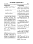
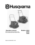
Trig-Tek
346B
Synthesized Calibrator
User Manual
Publication No. 980956 Rev. A
Astronics Test Systems Inc.
4 Goodyear, Irvine, CA 92618
Tel: (800) 722-2528, (949) 859-8999; Fax: (949) 859-7139
[email protected] [email protected]
[email protected] http://www.astronicstestsystems.com
Copyright 2011 by Astronics Test Systems Inc. Printed in the United States of America. All rights reserved.
This book or parts thereof may not be reproduced in any form without written permission of the publisher.
THANK YOU FOR PURCHASING THIS
ASTRONICS TEST SYSTEMS PRODUCT
For this product, or any other Astronics Test Systems product that incorporates software drivers,
you may access our web site to verify and/or download the latest driver versions. The web
address for driver downloads is:
http://www.astronicstestsystems.com/support/downloads
If you have any questions about software driver downloads or our privacy policy, please contact
us at:
[email protected]
WARRANTY STATEMENT
All Astronics Test Systems products are designed to exacting standards and manufactured in full
compliance to our AS9100 Quality Management System processes.
This warranty does not apply to defects resulting from any modification(s) of any product or part
without Astronics Test Systems express written consent, or misuse of any product or part. The
warranty also does not apply to fuses, software, non-rechargeable batteries, damage from
battery leakage, or problems arising from normal wear, such as mechanical relay life, or failure to
follow instructions.
This warranty is in lieu of all other warranties, expressed or implied, including any implied
warranty of merchantability or fitness for a particular use. The remedies provided herein are
buyer’s sole and exclusive remedies.
For the specific terms of your standard warranty, contact Customer Support. Please have the
following information available to facilitate service.
1. Product serial number
2. Product model number
3. Your company and contact information
You may contact Customer Support by:
E-Mail:
[email protected]
Telephone:
+1 800 722 3262
(USA)
Fax:
+1 949 859 7139
(USA)
RETURN OF PRODUCT
Authorization is required from Astronics Test Systems before you send us your product or sub-assembly for
service or calibration. Call or contact Customer Support at 1-800-722-3262 or 1-949-859-8999 or via fax at
1-949-859-7139. We can also be reached at: [email protected].
If the original packing material is unavailable, ship the product or sub-assembly in an ESD shielding bag and
use appropriate packing materials to surround and protect the product.
PROPRIETARY NOTICE
This document and the technical data herein disclosed, are proprietary to Astronics Test Systems, and shall
not, without express written permission of Astronics Test Systems, be used in whole or in part to solicit
quotations from a competitive source or used for manufacture by anyone other than Astronics Test
Systems. The information herein has been developed at private expense, and may only be used for
operation and maintenance reference purposes or for purposes of engineering evaluation and incorporation
into technical specifications and other documents which specify procurement of products from Astronics
Test Systems.
TRADEMARKS AND SERVICE MARKS
All trademarks and service marks used in this document are the property of their respective owners.
•
Racal Instruments, Talon Instruments, Trig-Tek, ActivATE, Adapt-A-Switch, N-GEN, and PAWS are
trademarks of Astronics Test Systems in the United States.
DISCLAIMER
Buyer acknowledges and agrees that it is responsible for the operation of the goods purchased and should
ensure that they are used properly and in accordance with this document and any other instructions
provided by Seller. Astronics Test Systems products are not specifically designed, manufactured or
intended to be used as parts, assemblies or components in planning, construction, maintenance or
operation of a nuclear facility, or in life support or safety critical applications in which the failure of the
Astronics Test Systems product could create a situation where personal injury or death could occur. Should
Buyer purchase Astronics Test Systems product for such unintended application, Buyer shall indemnify and
hold Astronics Test Systems, its officers, employees, subsidiaries, affiliates and distributors harmless
against all claims arising out of a claim for personal injury or death associated with such unintended use.
FOR YOUR SAFETY
Before undertaking any troubleshooting, maintenance or exploratory procedure, read carefully the
WARNINGS and CAUTION notices.
This equipment contains voltage hazardous to
human life and safety, and is capable of inflicting
personal injury.
If this instrument is to be powered the AC line (mains) through an autotransformer,
ensure the common connector is connected to the neutral (earth pole) of the power
supply.
Before operating the unit, ensure the conductor (green wire) is connected to the ground
(earth) conductor of the power outlet. Do not use a two-conductor extension cord or a
three-prong/two-prong adapter. This will defeat the protective feature of the third
conductor in the power cord.
Maintenance and calibration procedures sometimes call for operation of the unit with
power applied and protective covers removed. Read the procedures and heed warnings
to avoid “live” circuit points.
Before operating this instrument:
1. Ensure the proper fuse is in place for the power source to operate.
2. Ensure all other devices connected to or in proximity to this instrument are properly grounded or
connected to the protective third-wire earth ground.
If the instrument:
-
fails to operate satisfactorily
shows visible damage
has been stored under unfavorable conditions
has sustained stress
Do not operate until performance is checked by qualified personnel.
Publication No. 980956 Rev. A
346B User Manual
Table of Contents
Chapter 1 .........................................................................................................................1-1
Introduction .....................................................................................................................1-1
Specifications ................................................................................................................................. 1-2
Millivolts Output .......................................................................................................................... 1-2
DC Output Millivolt (plus/minus) ................................................................................................. 1-3
Square Wave Output.................................................................................................................. 1-3
SWEEP INPUT .......................................................................................................................... 1-4
Controls ...................................................................................................................................... 1-4
Displays (2) ................................................................................................................................ 1-4
Dimensions ................................................................................................................................ 1-5
Power ......................................................................................................................................... 1-5
Chapter 2 .........................................................................................................................2-1
Operation .........................................................................................................................2-1
Programming Functions ................................................................................................................. 2-1
Operation ........................................................................................................................................ 2-2
Grounds ..................................................................................................................................... 2-2
Frequency Set Up ...................................................................................................................... 2-3
Level Set Up ............................................................................................................................... 2-4
Units and Modes ........................................................................................................................ 2-4
Programmable Files ................................................................................................................... 2-4
Segment Programming .............................................................................................................. 2-4
Remote ....................................................................................................................................... 2-5
Save/File .................................................................................................................................... 2-6
Sweep Input and Sweep UP-DN ................................................................................................ 2-7
RS 232 Bus Remote Operation ...................................................................................................... 2-8
IEEE 488 Remote Operation ........................................................................................................ 2-12
Installing IEEE Interface Board Assembly TT-3869 ................................................................. 2-15
Chapter 3 .........................................................................................................................3-1
Performance Test Procedure .........................................................................................3-1
General ........................................................................................................................................... 3-1
Test Equipment .............................................................................................................................. 3-1
Test Set Up .................................................................................................................................... 3-1
Test Procedures ............................................................................................................................. 3-2
File: 99-Performance Test Program .......................................................................................... 3-3
Astronics Test Systems
i
346B User Manual
Publication No. 980956 Rev. A
Chapter 4 ........................................................................................................................ 4-1
Calibration Procedure .................................................................................................... 4-1
Test Equipment ...............................................................................................................................4-1
Procedure .......................................................................................................................................4-1
PC Output .......................................................................................................................................4-2
Distortion .........................................................................................................................................4-3
Chapter 5 ........................................................................................................................ 5-1
Trouble Shooting............................................................................................................ 5-1
Power Supply ..................................................................................................................................5-1
Front Panel Keypad ........................................................................................................................5-1
Save & Recall..................................................................................................................................5-2
Frequency .......................................................................................................................................5-2
Level................................................................................................................................................5-2
.
ii
Astronics Test Systems
Publication No. 980956 Rev. A
346B User Manual
List of Figures
Figure 1-1, 346B Synthesized Calibrator............................................................................................ 1-1
Figure 2-1, Front Panel Keypad ......................................................................................................... 2-2
Figure 2-2, Rear Panel Terminal Strip and BNCs .............................................................................. 2-3
Figure 2-3, 346B Layout ................................................................................................................... 2-15
Figure 4-1, 115-230 VAC Switch S1 .................................................................................................. 4-1
Figure 4-2, Adjustment Resistor R2 ................................................................................................... 4-2
Astronics Test Systems
iii
346B User Manual
Publication No. 980956 Rev. A
List of Tables
Table 3-1, Programming Functions ....................................................................................................2-1
iv
Astronics Test Systems
Publication No. 980956 Rev. A
346B User Manual
DOCUMENT CHANGE HISTORY
Revision
Date
A
05/18/2011
Astronics Test Systems
Description of Change
Document Control release
v
346B User Manual
Publication No. 980956 Rev. A
This page was left intentionally blank.
vi
Astronics Test Systems
Publication No. 980956 Rev. A
346B User Manual
Chapter 1
Introduction
The 346B Synthesized Calibrator unit, Figure 1-1, provides frequencies from
0.1Hz to 99999.9Hz in 0.1 Hz steps. The signal output is in millivolt and
picocoulomb levels with selected units of RMS, pk, pk-pk, or DC. Levels from
0.010 to 9999 millivolts or picocoulombs can be selected. The Frequency and
Level can be set either by the keypad on the front panel (local) or by the bus
(remote). Remote operation is an optional feature. The unit operates as a standalone unit without the remote bus. Frequency accuracy is 2 parts in 100,000 and
the level accuracy is 0.5% of set level ±0.2% of full scale.
Figure 1-1, 346B Synthesized Calibrator
The unit has non-volatile memory capacity to hold 24 files of 31 segments. Each
of the 31 segments can have different frequency, level and units. The segment
can be stepped manually or a dwell time between 1 and 9 seconds can be used to
step through the segments.
Integrated circuitry is used throughout. The components are packaged on a
printed circuit board with an integral power supply. A rack mount kit is provided
and the unit dimensions are 3.5” high, 19” wide, and 13” deep.
The MILLIVOLT output is converted to picocoulomb at the PICOCOULOMB
output. The frequency is the same; the picocoulomb level is the same as the
millivolts ±0.3%.
Astronics Test Systems
Introduction 1-1
346B User Manual
Publication No. 980956 Rev. A
Specifications
Millivolts Output
Impedance
Less than 20 Ohms.
Connector
BNC (front and rear panels).
Waveform Sinewave
Operating Temperature
0º to 70º C
Storage Temperature
-20º to 85º C
Level
9.999, 99.99, 999.9, or 9999 mV full scale
with RMS, PEAK, or PK-PK units.
Freq Range
0.1 Hz–99999.9 Hz
Distortion
5 Hz to 10,000 Hz
5 Hz to 5000 Hz
0.25%
5000 to 10,000 Hz
0.5%
10,000 to
99999.9 Hz
1%
Accuracy (Freq Set)
±20 ppm (0º to 70º C)
Level Set Accuracy
0.5% of settings ±0.2% FS from 1 Hz to
100 kHz.
Resolution
9999 mV Range
10 mV
999.9 mV Range
1 mV
99.99 mV Range
0.1 mV
9.999 mV Range
0.01 mV
Waveform: Triangular Wave
Level
9.999, 99.99, 999.9 or 9999 mV FS pk-pk
units
Level Set Accuracy
2% of settings ±0.3% FS 0.1 Hz to
100 kHz
Waveform: Square Wave
Introduction 1-2
Rise/fall time (10%-90%)
Less than 1.2 µsec
Asymmetry (@ 10 kHz)
Less than 1%
Astronics Test Systems
Publication No. 980956 Rev. A
346B User Manual
Level
9.999, 99.99, 999.9 or 9999 mV FS pk-pk
units
Level Set Accuracy
2% of setting ±0.3% FS
DC Output Millivolt (plus/minus)
Impedance
Less than 10 ohms.
Level
9.999, 99.99, 999.9 or 9999 mV DC full
scale.
Level Set Accuracy
±0.5% of setting ±0.2% FS
Resolution
9999 mV Range
1 mV
999.9 mV Range
.1 mV
99.99 mV Range
.01 mV
9.999 mV Range
.001 mV
Square Wave Output
Impedance
Less than 1k ohm (5 mA max)
Waveform
Square wave.
Level
0 to 4 V ±1 Volt.
Rise/Fall Time
Less than 1.0 µsec
Astronics Test Systems
Introduction 1-3
346B User Manual
Publication No. 980956 Rev. A
SWEEP INPUT
Wave Shape
Square wave 0 to 5 Volt level.
Frequency
Frequency equals 0.1 Hz/sec
(10Hz input is 1 Hz/sec).
Power Switch
Applies power to circuit, when ON.
Keypad Frequency Selector
Six digit selection by keypad for 0.1Hz
resolution.
Level Selector
Four digits 0.010–9999 settings of level.
Control
Selects RMS, Peak, pk-pk or DC units at
the output
Controls
Displays (2)
6 digit LED display (frequency)
4 digit LED display (amplitude)
5 LED's indicate (SEGMENT NUMBER)
4 LED's indicate (functions)
4 LED's indicate (units)
2 LED's indicate PROG (program)
or REM (remote)
Introduction 1-4
Astronics Test Systems
Publication No. 980956 Rev. A
346B User Manual
Dimensions
3.5" high
19" wide
13" deep
Power
Operates either 115 or 230 V RMS AC
power 50-400 Hz, at approximately 25
watts.
Astronics Test Systems
Introduction 1-5
346B User Manual
Publication No. 980956 Rev. A
This page was left intentionally blank.
Introduction 1-6
Astronics Test Systems
Publication No. 980956 Rev. A
346B User Manual
Chapter 2
Operation
Programming Functions
Table 3-1, Programming Functions
Astronics Test Systems
Operation 2-1
346B User Manual
Publication No. 980956 Rev. A
Operation
The 346B Synthesized Calibrator generates signals with frequencies from 0.1 Hz
to 99999.9 Hz with 0.1 Hz resolution. The level of the signal can be set from 0.1
to 9999 millivolts or picocoulombs. It can generate sinewave, triangle wave,
square wave, and DC. The following is a description of how to set the different
parameters using the front panel keypad, Figure 2-1.
Turn the unit on by placing the power switch to ON position.
Figure 2-1, Front Panel Keypad
Grounds
There are two grounds on the terminal strip on the back panel of the unit, Figure
2-2, marked SIG for signal ground and CHAS for chassis ground The signal
ground is the same ground as all the output BNC connectors. The chassis ground
is connected to the chassis and the third wire on the input power line. These two
grounds are connected together on the terminal strip when it is shipped from the
factory. Separate the grounds, if the chassis ground of this 346B is not the same
as the unit being tested.
Operation 2-2
Astronics Test Systems
Publication No. 980956 Rev. A
346B User Manual
Figure 2-2, Rear Panel Terminal Strip and BNCs
Frequency Set Up
To set a new frequency, press the
key. Enter the desired frequency
using the keypad. Do not enter any decimal point, since the decimal point is
always on the same location (0.1 Hz resolution). For example, to set the
frequency for 250.0 Hz, press the following keys:
After the
key is pressed, the PROG light will go off and the signal with
the new frequency will be at the output jacks.
In order to increase or decrease the frequency by the
key and then the
and
press the
decrease the Frequency setting of the unit.
Astronics Test Systems
and
keys, simply
keys. This will increase and
Operation 2-3
346B User Manual
Publication No. 980956 Rev. A
Level Set Up
To set a new level, press the
key on the keypad. Enter the desired level
using the keypad. (Make sure the Level is in millivolts or picocoulombs). For
example, to set the Level for 80.0 millivolts, press the following keys.
key is pressed, the PROG light will go off and the signal with the
After the
new Level will be at the output jacks. If 4 digits is entered for the Level, the
operator does not need to press the
key, it automatically enters the data.
In order to increase or decrease the LEVEL by the
the level key and then
Level setting of the unit.
and
and
keys, simply press
keys. This will increase and decrease the
Units and Modes
The 346B provides 7 different outputs. These are: +DC, -DC, Sine Wave RMS,
Sine Wave Peak, Sine Wave pk-pk, Square Wave pk-pk, and Triangular Wave
pk-pk. Simply press MODE UNITS and step through the seven different options
and observe the unit and mode LEDS.
Programmable Files
The 346B has an internal; non-volatile memory. The unit has the capability to
store 24 files, each file can have up to 31 segments that include a frequency level
and dwell time.
Segment Programming
When programming the segments of a file, the PROG STEP LED below the Freq
indicator, will indicate .which segment is selected. For example, if the light for 1
and 4 are on, it means the segment 5 (1 + 4 = 5) is selected and it shows the
frequency and level of that segment. While on that segment, the operator can
make a change on the level and frequency of tlie segment (note the mode and
unit selected at the time will be stored). In order to move to a different segment
press the
key and the segment number. For example, to select
segment 2, press the following keys:
Operation 2-4
Astronics Test Systems
Publication No. 980956 Rev. A
346B User Manual
The PROG Step Light should indicate 2, and the frequency and level for that
segment should show up on the indicators. It is also possible to increment the
segments by pressing the following keys:
This would move to the next segment and pressing:
would move to the previous segment.
Each segment has a dwell time associated with it. This time can be any number
between 1 to 9 seconds. This is used when the unit is programmed to step
through the 31 different segments, and dwell at each segment for the
programmed dwell time duration.
Press
and it shows the dwell time for that segment (it should
indicate 1 to 9.). If a new dwell time is desired, press any key between 1 and 9 to
change it to a new time, otherwise press
.
Once all of the 31 different segments have been programmed; the operator can
cause the 346B to step through each segment and dwell at each segment for the
preset time duration. This can be done either through the keypad or by using the
two terminals on the back panel.
the keypad, press
, and it will start the sequence. Press
again, and it will stop the sequence.
If there are less than 31 segments, set the dwell time for the segment after the
last segment for 0. For example, if there are only 10 segments, set the dwell time
for segment 11 for 0 second, and it will step through segments 1 through 10 and
then it will stop.
Remote
From the remote, apply +5 Volts to the ST/ST Terminal and it will start the
sequence. If you remove the +5 Volts, it will stop the sequence. Also if you apply
+5 Volts to the RESET terminal, it will move to the first segment on the program.
Therefore, if the test needs to start at segment one, first apply the +5 Volts to
RESET, then remove it and apply the +5 Volts to the ST/ST terminal.
Astronics Test Systems
Operation 2-5
346B User Manual
Publication No. 980956 Rev. A
Save/File
The 346B has non-volatile SRAM which allows it to save 24 different files. Each
file consists of up to 31 segments, or setups. Therefore, after all the parameters
have been set for the segments (or segment, whichever will be used), the operator
can save those segments, under a two-digit file number. Press
key, the
PROG Light comes on, and the frequency indicator indicates P. Enter two digits
(between 0 to 9) and then press
. If you make a mistake anywhere in the
and start over again. For example, to save under File 22,
sequence, press
press the following keys:
If the code PH appears on the display, it indicates the 24 files are filled and no
more files can be saved.
If the code EE appears on the display, it indicates a file with that file number
it will replace the old file with the new file, if
already exists. If you press
you press another key it will not save the file.
To recall a file, press
and the two digit file number and then the
key. For example, to bring up File 22, press the following keys:
To check the total number of files which have been saved, press
and then
. The number should appear on frequency indicator. Press any
key to go back to normal operation.
To see the file numbers press
appear on the display, simply press
and then
key. The first file number will
key again and it will indicate the next file
number until it displays LL which means the end of the files.
To delete all the files, press
You cannot delete a single file, but you can save a new file in place of the old file
number. For example, if you have File 22 which you don't need anymore, simply
save the next file under the File 22. This would copy a new file in place of the old
file which is no longer needed.
Operation 2-6
Astronics Test Systems
Publication No. 980956 Rev. A
346B User Manual
Sweep Input and Sweep UP-DN
The sweep input is a BNC connector on the rear panel. Input a square wave signal
with a level of 0 to 5 Volts at a frequency ten times the desired linear sweep rate.
The UP/DN terminal when at low level (0 Volt) causes the frequency to sweep
down and when at +5 Volt to sweep up.
The SWEEP UP can be activated by pressing the
and then
key. (There must be an input signal at the Sweep input jack on the rear panel).
Press the key
and it will sweep down. The
change the sweep direction. Press
Astronics Test Systems
and
keys are used to
and it stops the sweep.
Operation 2-7
346B User Manual
Publication No. 980956 Rev. A
RS 232 Bus Remote Operation
(The RS 232 Bus Assy TTI 4118 must be installed. See Fig. 2-3 for help in
installation.)
LIST OF RS 232 BUS COMMANDS
FR
Frequency
LE
Level
MD x
Mode x (0 to 6)
Tx
Dwell time x (0 to 9) Seconds
ST1
Start the stepping sequence
ST2
Start the stepping sequence
ST3
Start Sweep Up
ST4
Start Sweep Down
ST5
Stop the Sweep
SA SG xx
Save under segment number xx (01 to 31)
RC SG xx
Recall Segment xx (01 to 31)
SA FI xx
Save under file number xx (00 to 99)
RC FI xx
Recall file number xx (00 to 99)
OT SS
Output the Frequency, Level, and mode of
the present segment.
OT SG xx
Output Segment XX (01 to 31) status
OT FI
Output all the existing File numbers
NOTE:
Operation 2-8
All commands must be entered in capital letters, and there must be
one space between each command.
Astronics Test Systems
Publication No. 980956 Rev. A
346B User Manual
The MD Command could have 7 different possibilities:
Model,
Units
MD 0
DC
-DC
MD 1
DC,
+DC
MD 2
SIN,
RMS
MD 3
SIN,
PK
MD 4
SIN,
PK-PK
MD 5
TR1,
PK-PK
MD 6
SQ,
PK-PK
Depending on the waveform needed, one of these 7 modes should be selected for
each segment.
There is a 4-position switch marked S1 on the plug-in board for the RS 232
Interface. The following shows each switch setting for S1.
Position 1
Position 2
Position 3
ON
Speed 9600 bps
OFF
Speed 4800 bps
ON
Even parity, 7 character, 1 stop bit
OFF
Odd parity, 7 character, 1 stop bit
ON
Echo ON
OFF
Echo OFF
Position 4
Not Used
S2 Switch
Not Used
Input strings received over the RS 232 Interface are not executed or checked for
proper syntax until an input terminator is received. The valid terminator is LF (Line
Feed) or CR (Carriage Return).
The unit is set at 9600 baud rate, even parity, 7 character, 1 stop bit, and echo
OFF at the time of shipping factory. Therefore a communication port can be set
up as:
OPEN”COM1:9600=,E,7,E,,CS,DS,CD” AS #1
which is COM1 at 9600 baud rate, even parity, 7 character, 1 stop bit, disregard
clear to send, data set ready, and carrier detect.
Astronics Test Systems
Operation 2-9
346B User Manual
Publication No. 980956 Rev. A
The following shows some examples for different commands. To set the
frequency for 200 Hz, use the following command:
"FR 200"
If there are more than one parameter to be set, just list them continuously one
after the other. For example, to set the frequency for 500.6 Hz, Level for 20.8
millivolts rms sinewave (Mode 2), and dwell time of 5 seconds, use the following
commands:
"FR 500.6 LE20.8 MD 2 T 5"
Once all the parameters for a segment is set, you can save that segment under a
segment number. For example, to save under segment 20, use the following
command:
"SA SG 20"
You can combine the two above strings into one command:
"FR 500.6 LE 20.8 MD 2 T 5 SA SG 20"
You can recall a segment and bring up the parameters on that segment by using
the following command:
"RC SG 20"
This will bring up the parameters on segment number 20.
To save all 31 segments under a file number, use the command:
"SA FI 55"
This will save all the segments under File number 55. To recall a file, use the
command:
"RC FI 60"
This will bring up all the 31 segments, which have been saved under File number
60.
There are some commands which can be used to cause the unit to output the
proper information back to the computer. The command OT (output) should be in
front of the string of commands, to receive information back from the unit. For
example, if you need to receive the status of the present segment, use the
following command:
"OT SS"
The status information will be put in a buffer. Therefore, right after the output
command, the controller (computer) has to become a receiver in order to receive
the information in the buffer. The received information would look like the
following:
"FR 02000.0 LE 10.00 MD 2"
This indicates a sinewave of 2000.0 Hz at 10.00 millivolts RMS. To receive status
on Segment 8, use the following command:
"OT SG 08"
Operation 2-10
Astronics Test Systems
Publication No. 980956 Rev. A
346B User Manual
The received information would look like the following:
"FR 10000.0 LE 580.0 MD 3 T 4"
which indicates a sinewave of 10000 Hz with a Level of 580 millivolts pk and dwell
time of 4 seconds. If status of more than one segment is needed, just list them
continuously one after the other. For example, to receive status of segments, 4,
12, and 21, use the command:
"OT SG04 SG 12 SG21"
The received information will show the status of each segment in that order.
To check the existing file numbers in the unit, use the following command:
"OT FI"
The output would look like the following:
"05 files 08 42 55 66 12"
which means there are 5 files in the unit, with file numbers 08, 42, 55, 66, and 12.
Astronics Test Systems
Operation 2-11
346B User Manual
Publication No. 980956 Rev. A
IEEE 488 Remote Operation
The optional IEEE 488 Bus Assy TTI 3869 must be installed to operate in Remote
mode. See Fig. 2-3 for installation information.
LIST OF IEEE 488 BUS COMMANDS
FR
Frequency
LE
Level
MD x
Mode x (0 to 6)
Tx
Dwell time x (0 to 9) Seconds
ST1
Start the sweeping sequence
ST2
Stop the sweep sequence
ST3
Start Sweep Up
ST4
Start Sweep Down
ST5
Stop the Sweep
SA SG xx
Save under segment number xx (01 to 31)
RC SG xx
Recall Segment xx (01 to 31)
SA FI xx
Save under file number xx (00 to 99)
RC FI xx
Recall file number xx (00 to 99)
OT SS
Output the Frequency, Level, and mode of
the present segment.
OT SG xx
Output Segment xx (01 to 31) status
OT FI
Output all the existing File numbers
NOTE:
Operation 2-12
All commands must be entered in capital letters, and there must be
one space between each command.
Astronics Test Systems
Publication No. 980956 Rev. A
346B User Manual
The MD Command could have 7 different possibilities:
Model,
Units
MD 0
DC
-DC
MD 1
DC,
+DC
MD 2
SIN,
RMS
MD 3
SIN,
PK
MD 4
SIN,
PK-PK
MD 5
TR1,
PK-PK
MD 6
SQ,
PK-PK
Depending on the waveform needed, one of these 7 modes should be selected for
each segment.
The following shows some examples for different commands. To set the
frequency for 200 Hz, use the following command:
"FR 200"
If there is more than one parameter to be set, just list them continuously one after
the other. For example, to set the frequency for 500.6 Hz, Level for 20.8 millivolts
rms sinewave (Mode 2), and dwell time of 5 seconds, use the following
commands:
"FR 500.6 LE20.8 MD 2 T 5"
Once all the parameters for a segment is set, you can save that segment under a
segment number. For example, to save under segment 20, use the following
command:
"SA SG 20"
You can combine the two above strings into one command:
"FR 500.6 LE 20.8 MD 2 T 5 SA SG 20"
You can recall a segment and bring up the parameters on that segment by using
the following command:
"RC SG 20"
This will bring up the parameters on segment number 20.
To save all 31 segments under a file number, use the command:
"SA FI 55"
This will save all the segments under File number 55. To recall a file, use the
command:
"RC FI 60"
Astronics Test Systems
Operation 2-13
346B User Manual
Publication No. 980956 Rev. A
This will bring up all the 31 segments, which have been saved under File number
60.
There are some commands which can be used to cause the unit to output the
proper information back to the computer. The command OT (output) should be in
fiont of the string of commands, to receive information back from the unit. For
example, if you need to receive the status of the present segment, use the
following command:
"OT SS"
The status information will be put in a buffer. Therefore, right after the output
command, the controller (computer) has to make thr unit (346B)a talker in order to
receive the information in the buffer. The received information would look like the
following:
"FR 02000.0 LE 10.00 MD 2"
This indicates a sinewave of 2000.0 Hz at 10.00 millivolts RMS. To receive status
on Segment 8, use the following command:
"OT SG 08"
The received information would look like the following:
"FR 10000.0 LE 580.0 MD 3 T 4"
which indicates a sinewave of 10000 Hz with a Level of 580 millivolts pk and dwell
time of 4 seconds. If status of more than one segment is needed, just list them
continuously one after the other. For example, to receive status of segments 4,
12, and 21, use the command:
"OT SG 04 SG 12 SG 21"
The received information will show the status of each segment in that order.
To check the existing file numbers in the unit, use the following command:
"OT FI"
The output would look like the following:
"05 files 08 42 55 66 12"
which means there are 5 files in the unit, with file numbers 08, 42, 55,66, and 12.
Operation 2-14
Astronics Test Systems
Publication No. 980956 Rev. A
346B User Manual
Installing IEEE Interface Board Assembly TT-3869
1.
Remove top and bottom covers (3 screws at rear, 2 flat head screws at
center. Retain hardware.
2.
Remove screws, lockwashers on 2 threaded spacers on component side of
PC Board near transformers. Retain hardware. Refer to Figure 2-3.
3.
Slide Interface Board Assembly (TT-3869) into connector shell on rear
panel. Engage PI, P2 headers into Hi-profile sockets on main PC Board.
Push firmly into place after insuring: all pins are engaged.
4.
Install screws, lockwashers removed in Step 2 above to hold board
assembly.
5.
Re-install top and bottom covers using hardware removed in Step 1 above.
Figure 2-3, 346B Layout
Astronics Test Systems
Operation 2-15
346B User Manual
Publication No. 980956 Rev. A
This page was left intentionally blank.
Operation 2-16
Astronics Test Systems
Publication No. 980956 Rev. A
346B User Manual
Chapter 3
Performance Test Procedure
General
The test provides a method to test the 346B Synthesized Calibrator for
compliance to the manufacturer's specifications. The unit is designed with
integrated circuitry and very stable parts. Astronics Test Systems recommends
calibration on a one year schedule.
Test Equipment
Note: Equivalent test equipment may be substituted.
1. Digital Multimeter
Fluke 45 or equivalent (True RMS)
2. Frequency Counter
Leader LCD-822, or equivalent.
3. Oscilloscope
Tektronix 922
4. Distortion Analyzer
Hewlett Packard 334A
Test Set Up
A program file has been stored in memory under File Number 99. To recall File
,
,
#99, perform the following keystroke sequence
Set the program to segment #1 by performing the keystroke
and
.
entry,
,
,
, and
. The frequency should indicate 00346.2,
(coded for 346B), and the level indication will be 4 digits, with one digit to the right
of the decimal point.
NOTE: THIS FILE CAN BE ERASED. THE INFORMATION FOR THIS FILE HAS
BEEN INSERTED AT THE END OF THIS SECTION, IN THE EVENT THIS FILE
GETS ERASED.
Astronics Test Systems
Performance Test Procedure 3-1
346B User Manual
Publication No. 980956 Rev. A
Test Procedures
1. Select segment #2 by performing the following keystroke sequence,
and
2. Observe DC mode, DC units, 00000.0 Hz, 9999 mV.
3. Connect the DC voltmeter to the MILLIVOLT OUTPUT BNC Connector.
4. Observe 9999 ±70 mV indication on the DC voltmeter.
5. Select segment #3, by using the keystroke sequence,
and
.
6. Observe DC DC 00000.0 Hz, -999.9 mV with an indication of -999.9 ±7.0 mV on
the DC voltmeter.
7. Select segment #4 by the method used in Step #5 and observe DC DC,
00000.0 Hz, 99.99 mV with an indication of 99.99 ±0.70 mV on the DC voltmeter.
8. Select segment #5 and observe DC DC, 00000.0 Hz, 9.999 mV with an indication
of 9.999 ±0.07 mV on the DC voltmeter.
9. Connect a frequency counter to the SQUARE WAVE OUTPUT, and a true rms AC
voltmeter to the MILLIVOLT OUTPUT.
10. Select segment #6. Observe SIN RMS, 00100.0 Hz, 9999 mV with an indication
of 9999 ±70 mV rms on the AC voltmeter.
11. Select segment #7. Observe SIN RMS, 99,999.9 Hz, 9999 mV with an indication
of 99,999.9 ±2.0 Hz on the frequency counter, and 9999 ±120 mV rms indication
on the AC voltmeter.
12. Select segment #8. Observe, SIN RMS, 10,000.0 Hz, 9999 mV with indication of
10,000 ±0.2 Hz on the frequency counter and 9999 ±120 mV rms on the AC
voltmeter.
13. Select segment #9. Observe, SIN PK, 01000.0 Hz, 9999 mV with an indication of
7070 ±50.0 mV rms on the AC voltmeter.
14. Select segment #10. Observe SIN PK-PK mode, 01000.0 Hz, 9999 mV with an
indication of 3535 ±25 mV rms on the AC voltmeter.
15. Select segment #11. Observe SQ PK-PK, 01000.0 Hz, 9999 mV, with an
indication of 5000 ±115 mV rms on the AC TRMS voltmeter or 5550 ±115 mV rms
on the AC AVERAGING voltmeter.
16. Select segment #12. Observe TRI PK-PK, 01000.0 Hz, 3464 mV with an
indication of 1000 ±23 mV on the AC TRMS voltmeter, and 970 ±23 mV on the AC
AVERAGING voltmeter.
17. Connect an oscilloscope to the MILLIVOLT OUTPUT.
18. Select segment #6 and observe a clean sine wave with no distortion.
19. Press START/STOP and observe the waveforms as they appear. The intervals
are set for 5 seconds and will stop at segment #12.
Performance Test Procedure 3-2
Astronics Test Systems
Publication No. 980956 Rev. A
346B User Manual
20. Connect the calibrator mV OUTPUT to Distortion Analyzer to verify Distortion is
equal or less than the listed values with the mV OUTPUT level set at 9999
millivolts rms.
20 Hz
.25% (max)
100 Hz
.25% (max)
1 kHz
.25% (max)
10 kHz
.25% (max)
50 kHz
.5% (max)
100 kHz
1.0% (max)
File: 99-Performance Test Program
SEGMENT
FREQUENCY
MODE
LEVEL
UNITS
TIME
NOTES
01
00346.2
SIN
XXX.0
RMS
5
IS SEG
XXX IS THE
SERTIAL NO.
2
-
DC
9999
DC
5
SEG 2-5: SEG
3
-
DC
-999.9
DC
5
LEVEL
CHECKS
4
-
DC
99.99
DC
5
5
-
DC
9.999
DC
5
6
00100.0
SIN
9999
RMS
5
7
99999.9
SIN
9999
RMS
5
8
10,000.0
SIN
9999
RMS
5
9
1000.0
SIN
9999
PEAK
5
10
1000.0
SIN
9999
PK-PK
5
11
1000.0
SQ
9999
PK-PK
(AVG)
5
12
1000.0
TRI
3464
PK-PK
(AVG)
5
13
00346.2
SIN
3464
RMS
0
Astronics Test Systems
FREQ
RESPONSE
CHECKS
MODE
UNITS
CHECKS
Performance Test Procedure 3-3
346B User Manual
Publication No. 980956 Rev. A
This page was left intentionally blank.
Performance Test Procedure 3-4
Astronics Test Systems
Publication No. 980956 Rev. A
346B User Manual
Chapter 4
Calibration Procedure
The 346B Synthesized Calibrator is packaged on a single, printed circuit board. All
the adjustments are accessible from the top of the unit with the top cover
removed.
Test Equipment
Note: Equivalent equipment can be substituted.
Digital Multimeter
Keithley 191
Voltage to Charge Converter
Trig-Tek 2030
Charge Amplifier
Trig-Tek 203M
Distortion Analyzer
Hewlett Packard 334A
Procedure
Before turning on the unit, check the 115-230 VAC switch S1, Figure 4-1, near the
transformer for proper setting to accommodate the power to be used. Connect
the power cord to AC power and place the ON-OFF switch to ON.
Figure 4-1, 115-230 VAC Switch S1
Astronics Test Systems
Calibration Procedure 4-1
346B User Manual
Publication No. 980956 Rev. A
1. Connect the AC Voltmeter to the mV OUTPUT jack of the calibrator.
2. Select the SIN RMS mode. Set the frequency for 500.0 Hz and the level for
9999 millivolts (refer to Chapter 2 Operation).
3. Set the Level ADJ R2, Figure 4-2, for an indication of 9999 ±2 millivolts on the
AC voltmeter.
Figure 4-2, Adjustment Resistor R2
4. Select the SQ PK-PK mode.
5. Connect the oscilloscope to the mV OUTPUT.
6. Check that the rise and fall time (10 to 90%) are less than 1.2 µs at 10, 100,
1000, 10000, and 100000 Hz.
PC Output
The pC OUTPUT should vary less than ±0.5% from the mV OUTPUT. This
procedure provides a means of checking the pC OUTPUT.
The method used is to compare the voltage to picocoulomb converter at the pC
OUTPUT with a known converter, the 2030 Voltage to Charge Converter. The
2030 Voltage to Charge Converter is a precision 1000 pf capacitor with the proper
shielding to assure noise free measurements.
1. Connect the input of the 2030 Voltage to Charge Converter to the Calibrator
mV OUTPUT.
2. Connect the charge output of the Voltage to Charge Converter to the ACCEL
input of the charge amplifier 203M or equivalent.
3. Set the charge amplifier input to 10 pC/g, and the LP filter to HIGH.
4. Select the SIN PK mode. Set the frequency for 500 Hz and the level for 9999
millivolts.
5. Use the sensitivity controls to set the meter for an indication of the charge
amplifier for exactly 1000 g's.
Calibration Procedure 4-2
Astronics Test Systems
Publication No. 980956 Rev. A
346B User Manual
6. Move the charge amplifier input lead from the output of the voltage to charge
converter to the pC OUTPUT jacks front and rear panel. The new indication
on the charge amplifier should be between 995 and 1005 for each output (front
and rear panel).
Distortion
1. Connect the Distortion analyzer input to the calibrator mV OUTPUT.
2. Select the SIN RMS mode. Set the level for 9999 millivolts.
3. Check for less than 0.25% distortion at 10, 50, 100, 500, 1000, 5000, and
10000 Hz.
4. Check for less than 0.5% distortion at 20 k, 50 k, 70 k, and 100 kHz.
5. Disconnect all test equipment.
6. Replace the top cover (5 screws).
Astronics Test Systems
Calibration Procedure 4-3
346B User Manual
Publication No. 980956 Rev. A
This page was left intentionally blank.
Calibration Procedure 4-4
Astronics Test Systems
Publication No. 980956 Rev. A
346B User Manual
Chapter 5
Trouble Shooting
This Chapter provides the operator with information regarding troubleshooting of
the 346B.
The 346B consists of a mother board (Assy 3984), one indicator driver board
(Assy 4045), and two display indicator boards (Assy 4031). The two indicator
boards are plugged into the indicator driver board through a 12-pin SIP connector.
The driver board gets connected to the mother board through a 20-pin connector
and ribbon cable marked J1.
Power Supply
The Power Supply Section of the unit is located on the right side of the mother
board. The transformer marked T1 provides the +18 and -18 Volts, and
transformer T2 provides the +5 and -5 Volts.
Check the unit for 1/2 Amp Slow Blow Fuse, and be sure voltage selection
switcher S1, Figure 4-1, is in the proper position for the power input voltage and
the primary power voltage is within the ±10% limits.
Check the 4 regulators marked U1-U4 for the proper voltages.
Front Panel Keypad
Problem:
Unable to input anything from the keypad
1. Check the blue connector from the front panel key pad to the display driver
board. (Be sure it is plugged in completely).
2. The probable problem is the keyboard encoder. U3 on the display driver
board. (Replace the part).
Astronics Test Systems
Trouble Shooting 5-1
346B User Manual
Publication No. 980956 Rev. A
Save & Recall
Problem:
Cannot save or recall any file.
1. Check Chapter 2, Operation and make sure the procedure is followed
correctly.
2. All the memory for file is filled up and there is no more room for any more files.
Read to the SAVE/FILE in Chapter 2, Operation.
3. The SRAM could be bad. Replace U8 on the main board. Once the new
SRAM is installed, you have to delete all the files in the SRAM and program
the new files. (Refer to the SAVE/FILE in Chapter 2, Operation).
Frequency
Problem:
The unit reads a different frequency than is entered.
1. Make sure the ENTER key has been pressed; each of the 6 digits should
have a number in it.
2. The problem could be with any of the 5 counters marked U21-U25. Replace
one at a time to fix the problem.
3. The problem could also be caused by the I/0 ports. Replace the ports Ul7U20 one at a time to fix the problem.
Level
Problem: There is no output at the BNC connector.
1. Could be a problem with the +18 or -18 Volts on the power supply. Check the
regulators for proper voltages.
2. The output driver circuit could have been damaged, if there is a signal at pin 8
of U46 and no signal at pin 11 of U43 (any one of the transistor Q1-Q4 could
be bad).
Problem: The output level is not correct
1. Make sure the ENTER key has been pressed and each of the 4 digits should
have a number in it.
2. The unit may require calibration (Refer to Chapter 4, Calibration).
3. The D/A Converter could be bad. Replace U47 on the main board.
Trouble Shooting 5-2
Astronics Test Systems