1
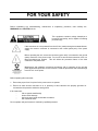
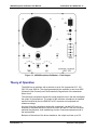
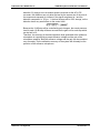
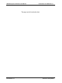
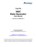
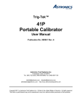
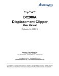
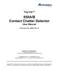
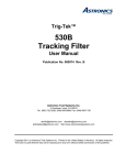
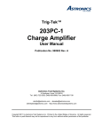
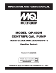
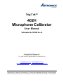
Trig-Tek™
402H
Microphone Calibrator
User Manual
Publication No. 980963 Rev. A
Astronics Test Systems Inc.
4 Goodyear, Irvine, CA 92618
Tel: (800) 722-2528, (949) 859-8999; Fax: (949) 859-7139
[email protected] [email protected]
[email protected] http://www.astronicstestsystems.com
Copyright 2011 by Astronics Test Systems Inc. Printed in the United States of America. All rights reserved.
This book or parts thereof may not be reproduced in any form without written permission of the publisher.
THANK YOU FOR PURCHASING THIS
ASTRONICS TEST SYSTEMS PRODUCT
For this product, or any other Astronics Test Systems product that incorporates software drivers,
you may access our web site to verify and/or download the latest driver versions. The web
address for driver downloads is:
http://www.astronicstestsystems.com/support/downloads
If you have any questions about software driver downloads or our privacy policy, please contact
us at:
[email protected]
WARRANTY STATEMENT
All Astronics Test Systems products are designed to exacting standards and manufactured in full
compliance to our AS9100 Quality Management System processes.
This warranty does not apply to defects resulting from any modification(s) of any product or part
without Astronics Test Systems express written consent, or misuse of any product or part. The
warranty also does not apply to fuses, software, non-rechargeable batteries, damage from
battery leakage, or problems arising from normal wear, such as mechanical relay life, or failure to
follow instructions.
This warranty is in lieu of all other warranties, expressed or implied, including any implied
warranty of merchantability or fitness for a particular use. The remedies provided herein are
buyer’s sole and exclusive remedies.
For the specific terms of your standard warranty, contact Customer Support. Please have the
following information available to facilitate service.
1. Product serial number
2. Product model number
3. Your company and contact information
You may contact Customer Support by:
E-Mail:
[email protected]
Telephone:
+1 800 722 3262
(USA)
Fax:
+1 949 859 7139
(USA)
RETURN OF PRODUCT
Authorization is required from Astronics Test Systems before you send us your product or sub-assembly for
service or calibration. Call or contact Customer Support at 1-800-722-3262 or 1-949-859-8999 or via fax at
1-949-859-7139. We can also be reached at: [email protected].
If the original packing material is unavailable, ship the product or sub-assembly in an ESD shielding bag and
use appropriate packing materials to surround and protect the product.
PROPRIETARY NOTICE
This document and the technical data herein disclosed, are proprietary to Astronics Test Systems, and shall
not, without express written permission of Astronics Test Systems, be used in whole or in part to solicit
quotations from a competitive source or used for manufacture by anyone other than Astronics Test
Systems. The information herein has been developed at private expense, and may only be used for
operation and maintenance reference purposes or for purposes of engineering evaluation and incorporation
into technical specifications and other documents which specify procurement of products from Astronics
Test Systems.
TRADEMARKS AND SERVICE MARKS
All trademarks and service marks used in this document are the property of their respective owners.
•
Racal Instruments, Talon Instruments, Trig-Tek, ActivATE, Adapt-A-Switch, N-GEN, and PAWS are
trademarks of Astronics Test Systems in the United States.
DISCLAIMER
Buyer acknowledges and agrees that it is responsible for the operation of the goods purchased and should
ensure that they are used properly and in accordance with this document and any other instructions
provided by Seller. Astronics Test Systems products are not specifically designed, manufactured or
intended to be used as parts, assemblies or components in planning, construction, maintenance or
operation of a nuclear facility, or in life support or safety critical applications in which the failure of the
Astronics Test Systems product could create a situation where personal injury or death could occur. Should
Buyer purchase Astronics Test Systems product for such unintended application, Buyer shall indemnify and
hold Astronics Test Systems, its officers, employees, subsidiaries, affiliates and distributors harmless
against all claims arising out of a claim for personal injury or death associated with such unintended use.
FOR YOUR SAFETY
Before undertaking any troubleshooting, maintenance or exploratory procedure, read carefully the
WARNINGS and CAUTION notices.
This equipment contains voltage hazardous to
human life and safety, and is capable of inflicting
personal injury.
If this instrument is to be powered from the AC line (mains) through an autotransformer,
ensure the common connector is connected to the neutral (earth pole) of the power
supply.
Before operating the unit, ensure the conductor (green wire) is connected to the ground
(earth) conductor of the power outlet. Do not use a two-conductor extension cord or a
three-prong/two-prong adapter. This will defeat the protective feature of the third
conductor in the power cord.
Maintenance and calibration procedures sometimes call for operation of the unit with
power applied and protective covers removed. Read the procedures and heed warnings
to avoid “live” circuit points.
Before operating this instrument:
1. Ensure the proper fuse is in place for the power source to operate.
2. Ensure all other devices connected to or in proximity to this instrument are properly grounded or
connected to the protective third-wire earth ground.
If the instrument:
-
fails to operate satisfactorily
shows visible damage
has been stored under unfavorable conditions
has sustained stress
Do not operate until performance is checked by qualified personnel.
Publication No. 980963 Rev. A
Microphone Calibrator User Manual
Table of Contents
Chapter 1 .........................................................................................................................1-1
Introduction .....................................................................................................................1-1
Description ..................................................................................................................................... 1-1
Dimensions ................................................................................................................................ 1-1
Weight ........................................................................................................................................ 1-1
Theory of Operation ....................................................................................................................... 1-2
Chapter 2 .........................................................................................................................2-1
Operation .........................................................................................................................2-1
General Information........................................................................................................................ 2-1
Charger & Battery ........................................................................................................................... 2-1
Percent LED’s ................................................................................................................................ 2-1
Test Manifold .................................................................................................................................. 2-3
Test Method ................................................................................................................................... 2-3
KNOWN Microphone ...................................................................................................................... 2-3
Extended Transducer ..................................................................................................................... 2-4
Controls .......................................................................................................................................... 2-5
POWER Switch .......................................................................................................................... 2-5
Frequency Selector .................................................................................................................... 2-5
Level Selector............................................................................................................................. 2-5
External Frequency Switch......................................................................................................... 2-5
Chapter 3 .........................................................................................................................3-1
Performance Test............................................................................................................3-1
Test Equipment .............................................................................................................................. 3-1
Switch Settings ............................................................................................................................... 3-1
Frequency Test Procedure ............................................................................................................. 3-2
Level Test Procedure ..................................................................................................................... 3-2
Chapter 4 .........................................................................................................................4-1
Calibration Procedure ....................................................................................................4-1
Conversion ..................................................................................................................................... 4-1
Test Equipment .......................................................................................................................... 4-1
Calibration Procedure ..................................................................................................................... 4-2
Setting the 160 dB Level ............................................................................................................ 4-2
Setting Frequency ...................................................................................................................... 4-2
Astronics Test Systems
i
402H Microphone Calibrator User Manual
Publication No. 980963 Rev. A
List of Figures
Figure 1-1, 402H Microphone Calibrator – Front Layout ....................................................................1-2
Figure 2-1, 402H Battery Life Data at 1000 Hz ...................................................................................2-2
Figure 2-2, 402H Cable Assembly ......................................................................................................2-4
ii
Astronics Test Systems
Publication No. 980963 Rev. A
Microphone Calibrator User Manual
List of Tables
Table 2-1, Sound Transducer Frequency Response (Nominal)......................................................... 2-3
Table 4-1, Transducer Conversion Table........................................................................................... 4-1
Astronics Test Systems
iii
402H Microphone Calibrator User Manual
Publication No. 980963 Rev. A
DOCUMENT CHANGE HISTORY
iv
Revision
Date
A
12/5/2011
Description of Change
Document Control release
Astronics Test Systems
Publication No. 980963 Rev. A
402H Microphone Calibrator User Manual
Chapter 1
Introduction
Description
The 402H Microphone Calibrator (Figure 1-1) is designed to provide portable
calibration of high intensity microphones and pressure transducers. Modified to
add flexibility to the original 402A design, the 402H offers the ability to extend the
sound source up to twenty five feet from the base unit using a provided cable.
The 402H is housed in a portable carrying case (12" x 12" x 7.5") and is designed
to provide storage for the hand held sound transducer and extension cable.
The 402H Microphone Calibrator is capable of delivering sound pressure levels
from 120 dB to 160 dB selectable in 10 dB increments and is accurate to ±1.0 dB.
The test manifold, which interfaces both the unknown and reference microphones
to the sound transducer, is designed so that both microphones share a common
cavity. The output of the reference or "known" microphone is used in a closed
loop control to maintain an accurate sound pressure level in the test manifold.
Five internal frequencies: 62.5, 125, 250, 500 and 1000 Hz are selectable from
the front panel. A BNC connector is provided to accommodate an external
frequency source.
The 402H is completely self contained and comes with the following components:
Hand held sound transducer (with fitted cover), 25' cable (with storage pouch),
wrist strap, cable stress relief strap, rechargeable lead acid battery, reference
pressure transducer test manifold, microphone adapter (of your choice),
calibration plug and power cord.
Dimensions
Case
12'' x 12" wide x 7.5" high
Sound Transducer
4.5" dia. x 5.5" high
Case
23 lbs. with sound transducer
Sound Transducer
6 lbs
Weight
Astronics Test Systems
Introduction 1-1
402H Microphone Calibrator User Manual
Publication No. 980963 Rev. A
Figure 1-1, 402H Microphone Calibrator – Front Layout
Theory of Operation
The 402H has an oscillator with a selector to set in five frequencies 62.5, 125,
250, 500, and 1000 Hz. The signal generated by the oscillator is sent to an AGC
(Automatic Gain Control) circuit that controls the signal level of the transducer
driver circuit.
The reference microphone senses the sound pressure level in the test manifold at
the output of the transducer. The output of the reference microphone is amplified
and then rectified by the true RMS AC to DC converter and compared to a
reference voltage.
Any error from the comparison causes the compressor, via the AGC circuit to
increase or decrease the input to the drive circuit until the DC from the converter
matches the reference, thus maintaining a known, fixed sound pressure level in
the test manifold.
Because of the nature of the driver transducer, the output can have up to 5%
Introduction 1-2
Astronics Test Systems
Publication No. 980963 Rev. A
402H Microphone Calibrator User Manual
distortion. By using a true root means square conversion at the AC to DC
converter, the distortion can only alter the level by the square root of the sum of
the components squared; for instance if the signal component is 1 and the
distortion component is .10% or .1, the level change will be .05% change, so the
distortion has a very small effect on the control level.
Because the 10 dB step will be controlled by gain changes, the sound pressure
level for each 10 dB step will be as accurate as the gain set for each step which
can be held ±1%.
Therefore, the accuracy of the sound pressure level generated at the reference
microphone is controlled by a preset reference voltage and the gain of the
microphone amplifier. Both the reference voltage and the gain can be controlled
very accurately. So the calibration accuracy of the system will ultimately be the
precision of the reference microphone.
Astronics Test Systems
Introduction 1-3
402H Microphone Calibrator User Manual
Publication No. 980963 Rev. A
This page was left intentionally blank.
Introduction 1-4
Astronics Test Systems
Publication No. 980963 Rev. A
402H Microphone Calibrator User Manual
Chapter 2
Operation
General Information
For proper operation, it is necessary that the microphone to be tested be
installed in the test manifold with the appropriate microphone adapter. If there
are any questions regarding proper microphone adapters, contact the
manufacturer.
Charger & Battery
The 402H Microphone Calibrator can be operated with AC or DC power. It has a
rechargeable lead acid battery which will operate for up to four hours on a single
charge. AC requirements are 115 to 230 VAC at 50 to 400 Hz.
An internal switch marked S1, internally located next to the power transformer
allows you to switch between 115 and 230 VAC operation. The unit is set to 115
V at the factory. A LOW BATT LED illuminates when the battery is completely
discharged.
CAUTION
Do not operate the charger with 230 VAC of power if switch (S1)
is in the 115 V position. Damage may result to the charger and/or
battery.
NOTE:
Do not allow the battery to remain completely discharged
for more than 3-4 hours. This can result in permanent
damage to the battery.
Percent LED’s
The percent charge LED circuit provides continual monitoring of the battery
charge. Four LED's display above 80, 60, 40, and 20 percent charge. The 0
percent LED illuminates when the battery voltage is below operating level.
See Figure 2-1 to determine the battery life.
Astronics Test Systems
Operation 2-1
402H Microphone Calibrator User Manual
Publication No. 980963 Rev. A
Figure 2-1, 402H Battery Life Data at 1000 Hz
Operation 2-2
Astronics Test Systems
Publication No. 980963 Rev. A
402H Microphone Calibrator User Manual
Test Manifold
The 402H is equipped with a test manifold which interfaces the known and
unknown microphones to the sound transducer. In this manifold, the two
microphones share a common cavity and are located adjacent to one another.
The known microphone fits securely in the manifold with a metal hold down nut.
The unknown microphone must be installed using an adapter made specially for
the microphone being tested. For best results, an air tight seal is desired
between the microphone to be tested and its adapter. These adapters can be
purchased from EADS North America Test and Services. Custom adapters will
be considered on request.
Test Method
The known microphone is measured using a True RMS Detector. In order to get
an accurate comparison, it will be necessary to measure the unknown
microphone with a charge amplifier that also has True RMS Detection. In the
case that the unknown transducer is a millivolt type, a current source will be
needed. An EADS North America Test and Services 203M Charge Amplifier or
equivalent is recommended.
KNOWN Microphone
The reference (KNOWN) microphone used in the 402H is a MIC62 (OEM from
Dytran Instruments). The sensitivity and certificate of calibration for the
microphone will be shipped with the unit. Manufacturer specified accuracy of this
microphone is ±0.5 dB @ 120,130, 140, 150 and 160 dB SPL (Sound Pressure
Level). The calibration is in peak millivolts lb/in 2 .
Table 2-1, Sound Transducer Frequency Response (Nominal).
Astronics Test Systems
SPL dB
Frequency Range
160
20-2000
150
20-2500
140
20-3000
130
20-3000
120
20-4000
Operation 2-3
402H Microphone Calibrator User Manual
Publication No. 980963 Rev. A
Extended Transducer
The 402H provides a portable transducer to allow testing microphones that are
installed. A 25-foot cable is standard (Figure 2-2). Other length cables can be
supplied on special order.
Figure 2-2, 402H Cable Assembly
Operation 2-4
Astronics Test Systems
Publication No. 980963 Rev. A
402H Microphone Calibrator User Manual
Controls
POWER Switch
The POWER switch is a two position switch marked ON and OFF. In the ON
position, the unit will operate in either mode, AC or DC. The LED next to the ON
marker should illuminate. In the OFF position, the unit is ready to charge. The
LOW BATT Led will illuminate when the battery charge drops below a usable
level.
Frequency Selector
This five position rotary switch allows selection of the available internal
frequencies: 62.5, 125, 250, 500 and 1000 Hz.
Level Selector
This five position rotary switch allows selection of dB level from 120 to 260 in 10
dB increments.
External Frequency Switch
This switch allows the use of an external frequency source. In the (INT) position,
the internal oscillator is activated making five frequencies selectable from the
front panel, 62.5, 125, 250, 500 and 1000 Hz. In the (EXT) position, the
corresponding BNC connector is activated making it possible to introduce a
signal from an outside source. External frequency input voltage is 5 Volts RMS.
Astronics Test Systems
Operation 2-5
402H Microphone Calibrator User Manual
Publication No. 980963 Rev. A
This page was left intentionally blank.
Operation 2-6
Astronics Test Systems
Publication No. 980963 Rev. A
402H Microphone Calibrator User Manual
Chapter 3
Performance Test
This Performance Test Procedure should be run to verify that the unit is
performing within the manufactured specifications. The unit uses integrated
circuits and very stable parts and should not require calibration more than once
every six months, unless a part fails. In the event that a reading is out of tolerance
the unit may require calibration see (Chapter 4) of this manual.
Test Equipment
Equivalent test equipment may be substituted.
Digital Multimeter
Keithley 179 (TRMS)
Frequency counters
Fluke 1900A
Switch Settings
Prior to turning the 360C power ON, set the switches to the following:
•
Frequency Hertz switch to 1000
•
dB SPL switch to 160
•
INT/EXT switch to INT
•
POWER switch to ON.
After you turn the POWER switch to ON, verify that the Power LED is ON and
BATT LOW LED is OFF.
Note: Since we are checking the performance of the 402H using the KNOWN
microphone secured in the test manifold, the other two ports must be
plugged. Use either plugs provided or the UNKNOWN microphone.
Astronics Test Systems
Performance Test 3-1
402H Microphone Calibrator User Manual
Publication No. 980963 Rev. A
Frequency Test Procedure
1. Connect frequency counter and multimeter to microphone output.
2. Observe the 1000 ±50.0 Hz indication on the frequency counter.
3. Place the FREQ HZ Switch to 500.
4. Observe the 500 ±25.0 Hz indication on the HZ FREQ counter.
5. Place the FREQ HZ Switch to 250.
6. Observe the 250 ±12.5 Hz indication on the FREQ counter.
7. Place the FREQ HZ Switch to 125.
8. Observe the 125 ±6.25 Hz indication on the FREQ counter.
9. Place the FREQ HZ switch to 62.5.
10. Observe the 62.5 ±3.125 Hz indication on the FREQ counter.
Level Test Procedure
In order to test output levels you must refer to Operation (Chapter 2) of this
manual. Using the Conversion table (Table 4-1 in Chapter 4), determine millivolts
for 160 dB-120 dB SPL. The sensitivity of the KNOWN microphone is given on
the calibration certificate (2013M9 Dytran).
Example: A microphone with sensitivity of 750 mV/ lb/in 2 . = 217.6
mV/160 dB. .29 x (sen) mV/lb/in 2 . = mV for 160 dB SPL.
1. Place dB SPL switch to 160.
2. Observe (calculated mV/160 dB) ±5% on the multimeter at the microphone
output.
3. Repeat Steps 1 and 2 for 150 dB, 140 dB, 130 dB, and 120 dB.
Performance Test 3-2
Astronics Test Systems
Publication No. 980963 Rev. A
402H Microphone Calibrator User Manual
Chapter 4
Calibration Procedure
The Calibration of the 402H is based on the traceability of the Reference
Microphone. Because the calibration of the Reference Microphone is done in
static mV / lb / in 2 units, it is necessary to do the conversion to SPL dB.
Conversion
The units commonly used to calibrate microphones and pressure transducers are
static millivolts/lbs/in 2 . It will be necessary to convert these units to mV/ SPL dB.
A conversion table and explanation is offered below. It has been established that
2.9 x 10 −9 mV RMS/ Ib/in 2 = 0 dB SPL RMS, because the microphone is
calibrated using static pressure. The following method should provide the proper
conversion.
Table 4-1, Transducer Conversion Table
mV/160 dB = .29 x mV/lb/in 2
mV/150 dB = .092 x mV/lb/in 2
mV/140 dB = .029 x mV/lb/in 2
mV/130 dB = .0092 x mV/lb/in 2
mV/120 dB = .0029 x mV/lb/in 2
Test Equipment
Equivalent test equipment can be substituted.
TRMS Meter
Keithley 179A
Digital Counter
Leader LDC-822
Astronics Test Systems
Calibration Procedure 4-1
402H Microphone Calibrator User Manual
Publication No. 980963 Rev. A
Calibration Procedure
Setting the 160 dB Level
1. With the power OFF and the Reference microphone in place, insert the
calibration plug in the manifold in place of the UNKNOWN microphone.
2. Place the FREQ Hz selector to 500.
3. Place the dB SP LEVEL switch to 160.
4. Place the POWER switch to ON.
5. Connect the TRMS AC voltmeter to the MIC OUTPUT jack.
6. Set the 160 dB ADJ for the Peak or RMS millivolt number found in the above
calculation ±I% on the TRMS AC voltmeter.
NOTE: Set R2 on the OSC & Driver Assembly for the proper range.
Setting Frequency
Note: Remove the unit from the case prior to beginning this calibration.
1. Place the FREQ HZ selector to 62.5 Hz.
2. Leave the dB SP LEVEL switch set to 160 dB.
3. Connect the counter to the MIC OUTPUT jack.
4. Adjust R2 for 62.5 ±1.8 Hz.
5. Place the FREQ HZ selector to 125 Hz.
6. Adjust R6 for 125 ±3.7Hz.
7. Place the FREQ HZ selector to 250 Hz.
8. Adjust R5 for 250 ±7.5 Hz.
9. Place the FREQ HZ selector to 500 Hz.
10. Adjust R4 for 500 ±15 Hz.
11. Place the FREQ Hz selector to 1000 Hz.
12. Adjust R3 for 1000 Hz ±30 Hz.
Calibration Procedure 4-2
Astronics Test Systems