1
A-PDF MERGER DEMO
GridForce
(Grid For Research Collaboration and Education)
© 2004 Bina Ramamurthy
(Supported by : NSF CCLI A&I DUE -0311473)
Dr. Bina Ramamurthy
A-PDF MERGER DEMO
! " !#$
%'&)(*(+,-,-.
/1032 &546&)78&)7:9<;>=@?)A
B +-C /ED (*(GFH&-(3(JIK D (MLONQPSRTU. BV ,SIGWYXZ=\[ B , V
]1^`_ D FHaZ9!;@bcLdKeKe?gfS[h,-,8T B ,S[h.-,Q&)7
i b D ; 2 &)7 D LOj 032 &Sk _ b D [ljm9'n
&)(oa![ Dp 9
i 4rqL
?)=s=ut
Lov-vwxwxwy[ _ b D [ljm9'n
&)(oa![ Dp 9mvz); 0*p<{ a); _ D v 032!p<D Xm[h?)=u7
|~}1y
<
r!1
QlsHlcQs6 xH¡Y¢QH¡o£Qc xs£\¢¤c¤cl>£Q¥sl£¦¢QHQsl¥£S§ 1¨ls xs£©¢¤u¢l£ªc£Q«Qs¨l>¬ xs£©¢6c¡
hu¥6c6¢®¢>`¬¢s xE£Q>Q£¥¯s£Q£Q>¢l£`s¢¤@®lQ x>£\¢>§s°>£\¢Ec£QQl£¥§
£©¢¨Qs>e>c x eQ£Ql>@¢l£S§
¢c¤c¥cE @£-@¥> 1>£\¢>§S¢¤@¢Ec£Q¯¬£c xles 1¨Z£Q>£\¢s£±¥¤@¢l£S§Ss£QsQs£Qs¬²c£Q:¬£¤£Ql³>@¢lc£'´µJ¢Yll¶cl
s°\·lQs>l@¢>²¢rQl¢®¢s8c®¸ss¢QU8c 1c®ll¹¢M¬\§Ss>¢M¬§S£-@ xl£Q¥yc£Q:u¢l£S´·º¶®lEl¢£Ql
®Zxc£c¬³ss»@¢·°c@lQ·l°\sl·¡¥@¤c£©l@¢M¬:Ql£Q¥yc®¸ss¢s§'¨Qs>ss§!s°>ss§!>c 1¨Z£Q>£\¢Oc£Q»¡o¤@ xs@¼s´xQ
sl-¡os
£1¨Q¤c¢l>cQ¢£QG°\
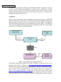
¢Q>c¢l>cQ¡½@ cl xc£Qs°\¾¿lQYc£Qx xlQQl¾3@¢sUQ£Q¥c¬1°\
slls£\¢¾¿lQc´ÀcÁ-ÂÃÄ¿ÅcÆ<ÅcÇ3ÇJÂÈ-Ç*Ä3É@È8ÊĽÆoƶˤÂÌ@ĽÍ@ÂÈ8Ç*ÎÂxÂUÏ6ÂUÐJÌ@ĽÈÌrÇJ¤ÃUÎ\ÈZÉcÆÉÌcÑyÉÒÌcÐUÄ3ÓäÉ@ÏÁ)ÔÇ*ĽÈÌ\ÕÖ!ÎÂÌ@ÐUÄ¿ÓäÉ@ÏYÁ)ÔQÇ*ÄoÈÌrÆÅ\ËU×eÅ@ÐÂ
פÔÁ\ÁÉ@ÐÇJ¤Ó:ËÑ8ÅrÌcÐÅ@È-Ç<Ò¤ÐÉ@ÏÙØdÅcÇ*Ä¿É@È)ÅcÆÀZÃÄ¿ÂUÈZäÂ1Ú!É@ÔÈZÓ\ÅcÇ*Ä3É@È`ÛHÜSÝßÞ@àá\ásâSãàrä£Qss¨Q¢d¢QQls»l®Z6@¨Q¨-ls»¢H°\
¨Qc®ls x1l£°c@Q1Q c£QxQ¤«@EslsE@lS§Gs d®Z>QQs¦¬¢s xs§
>>¢£Qlr @¼\¢¨hcsc£Q¦@¨Q¨ll>@¢£
°\ss´yå\¢Qs£\¢Olc¼8l£»cUQs¢¤@¢s5¥@¨-O¡¢My¢8sl¹¾¿±£Q>»>¨Z£Q¹®-l¹¢lsec£5 xlQQl@¾3®-c>
¨Q@¸ss¢s´GQ·lS®Zd1 1l¾¿> 1>¢c> 1>£\¢c£Q²E±-£c'æQc y´
ç £6s 1¨l¢l£¡Z¢QlG>cQc§O¢Qs£\¢ll®Zu®-¢dQ>¥£rc£Q6l E¨-> 1>£\¢OQl¢®¢su¨¨l>@¢l£S§c£Ql
®Zdu®-·¢6@£-@¬³sd1Ql¢¹®-¢sH¬¢s ¡½c¹¢Y@¤Q¢ss¢c§-c¥c¹¢ 1s§-¨Qc¢sc£Q²°lsss´å\¢Qs£\¢l!>°\
¥©HQ£QQs¢¤@£Q£¥c£Qyc¼l£Q¥x¼£>ls¥cO¡¶¥cy> E¨-¢£¥´
|$èsée¶ê Y>ëyì1
í©îï$ð!ñò©òó-ð!ñô\òcõ©í ö÷@øù@úüû\ýò
þQùÿ ÷ @ú ùù ÷ù)ù>ú©ÿ÷ùúù ÿcù ÿ÷Q÷ñ
5
"!rHs$#&% ('rm
8}6}*)r
۷ĽפÇ*ÐUÄ¿ËÔÇJ¤ÓÀ-Ñ@×UÇJÂÏE×+-,
É@ÈZäÂJÁZÇ*×Å@ÈZÓÛeÂפÄÌcȧ@®©¬/.e´\äcls§0Q´1ll xc@£e´2·l£Q®Zs¥§\Q*3
¹¢l£S§4Q£¾
>s¬rµM£c´l§ 6778c´
4 D _ aZ757 DQ2<p!Dp a)t'= 0 a 2 &-(b9!t¶t¶( D 7 DQ2 =ub
8c$
´ .Yl:ä 1¨¢l£Q¥ 9;::@¼l£Q<¥ .lc®-c'µM£¡h¤c¢Qs¢O> =>cl¹¢M?¬ 3
¹¢c 9A@Q¤cC£ B c£S§ 0 D)E¬ @->æHc£Q²<£\E¬ Fs¬§
0@¸£ 5 ls¬y@£¯åc£sG
§ 4Y¨QlH 677I©´
6´ÚZÔÈZÓ\Å@Ï6ÂUÈ-ÇJÅcÆ ×EÉÒY۷Ľ×UÇ*ÐUÄ3ËÔÇJ¤K
Ó JMË L>ÂÃsÇ
À-Ñ@×UÇJÂÏE× +xÖ!ÎN ,OJ;PRQTSUÂÐU׿Á¤ÃÇ*ĽÍcÂU§Q®W¬ V<´-<@3§ ç G´ B¼ss§ 5 ls¬rµM£©¢¾
å©>>£QsOº
Q®'´§ 6778c´
8
A-PDF MERGER DEMO
´ ÅcÇ3ÇJÂUÐUÈ JÐUÄ3ÂÈ-ÇJ¤ӪÀZÉÒUÇ*ÊÅ@РSYÐÃUÎ\Ä*ÇJ¤ÃÇ*ÔР+ UÅcÇ3ÇJÂÐUÈQ×6ÒÉ@Ð,
É@ÈZÃUÔÐUÐÂÈÇHÅ@ÈZÓ¦ØdÂÇ*ÊÉ@ÐcÂ¤Ó J ËMLs¤ÃsÇ*× +ÉcÆ ÔÏ®©¬
å©UQ x¢>§Så\¢¤c3§=Yc£Q¢>§-c£QCB¤Q c£Q£S§0c£¾ 5 ll¬yc£Q:å©£Qs§6777´
´ Å@ÍcÅ +OÉ@ÊÇJ/É UÐÉÌcÐÅ@ÏE§®<¬ 1·s¢s!@£? 1·s¢s3§Qº
s£©¢>¾ Fc'µM£Q´§6777´
I $U
Y$!6²><Um
c´äå37äå3TI7 c²\¹°@ls£©¢ . ¡oQ£Q-u¢l£ l£ ¨Qc®ls c°£¥§OQ>¥£ s¨Qs>£\¢¤@¢£S§d@£ c®Q¸>¢¾
c>£\¢sHQ>¥£H x¢QQl¥@¬yc£Q²@¨Q¨l@¢£S´
ºc£²¡ocYQsl¥£Hc£QHQs°\sl@¨- 1>£\¢Y£C0\>°´
6´ 5 c¼£¥E¼£QlsQ¥O¡
ä c£QC 0\>°c1¨Q¥c¤@ x xl£Q¥lc£Q¥c¥ss´
IO
´ 4Yås£Qlc@£K .Y¤cQ@¢s¨-@¢>¹¨-@¢l£Q¥x£H 77El°\s<ä 1¨¢så©>>£QsOc£Q? 3
£¥cl£Q>l£Q¥xsh@¢lcQ x>
¢@¢¬\cH@·>@¨-@®l¡<l>@£Ql£Q¥1£Qs ¨Q¥c¤c x 1l£Q¥xh@£¥c-@¥>@£y®Q¤@lsl£ xl£Q c!@ xQ£\¢¡!¢l xc´ G
QQl²cl1®ZO¡½c xlhu¢yc®¸ss¢¾¿@ls£©¢sy xQsll£Q¥Q§ x©£HsQOQsl¥£Hc£QHQs®Q¥¥£¥1¨Q¤c¢ls>s´
8
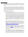
é ²# >ëyì
¯l¢ 3
æQ@ x 6
@m£c 3
æQc º
@¸>¢# I!
:
877"!
E¨Z£©¢
E¨Z£©¢
E¨Z£©¢
677
677
I77
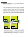
m£-@<l¢¢s¥c¤cQ>l!®Z·®)@>²£H¢Q$*s d®£s%!°\¤c!¨Z>s£\¢¤c¥dc¡
c!¢QO¢s xl¢s¯@®Z°\c´(4&(')*!¤§4Y¾
('7+),' !¤§ B-.(/0),/'!¤§ B&(/7+),/ !¤§ B¾ 213+),13'!¤§
ä 217+)41 !¤§
5
ä (60),6'!¤§
äG¾ (67$),6 !¤§ 1#(0),'!¤§ 1
(7)+ !¤§ @7*ls¢-@8
£ 7"!¤´GQ¨Zls¬rl®Q¸>¢¢x¤-@£¥c´
µM¡<£sssS§Q¢Q·l£QQ°c's 1¨Z£Qs£©¢@£¢°\¤cl
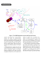
¥c¤cQslZ®S·@¨Q¨@¨l@¢s¬r>°\sS:´ 9 2 a); p!D ;x=>a`t!&-b>bE=u? D _ aZ9<;ub D A)aZ9«789!b=r?'<& ; D &»t<&b>b 032 z5z);& p!D:032 D ; D ;uA
_ aZ7»ta 2!D2 =a { =u? D _ aZ9!;@b D ( 0 b= Dp &-j=a ; D [
@
é
> ' ?
H x¢s æQc 1s§<£Qc¡G¢1sæQ@ x·l®ZxQ>8®Ss¡½@1¢Qxhc¢O@¢1¢ 4 >¥£»¡o ¢Qxsc´ @ml£csæc l<®SeQ>:Ql£Q¥r¢Qes¥Qh@¹¬²¤sQQls:±£c¶sæc s¼Z´ :¯l¢s æQc l¶>>°\s·u¨¨Qæl @¢s¬ 6@ß¡m¢
@¢h@
c£Q:¢QE±£cmsæc lm®Z1s 1¨QsQ>£Q°´ A x@¼\1¨»sæQ@ ll¶®Z1¥¹°\s£8£Q>·c¢QsE¢1Oc£
梤ccQl£@¬6cc£'´
}·!
QYQQY@¢¡½c@Ux¨@¸>¢Gl®Zc£Q£QQ£ss6Qs£6¹¢lc¥£Q>S´ 4l¢Q>>Qc§QsQ x>£\¢¤@¢£S§ u¼\s±§
@¢¤·±lss§Q@£ =R3A4$1 : 3`±ls@¢·®ZY®- 1¢¢src£Q¾¿l£Qc´
QYQs¢¤cl¡SQª¢d®- 1¢¥¹°\>£6clc£¥O¹¢¬\±Q¢
¨Q@¸ss¢>´
:lm>°\E¢¡½l ¢QEQ>·¡oc¢Q1c¢Q·¨Q@¸s¢¢©Q´dº
@¸ss¢l¶®SE¥c¤cQs8¡oc>8 77r¨Z£\¢·@U
c£Qy¢Q¢c¢¤cZ¨Q@¸ss¢¨Z£©¢l£QslQQl£Q¥6c£\¬r®Z£©Q>lS®S·>clsy¢NI77E¨Zl£\¢Y@l£QQl>@¢sHl£¢Q·¥c¤cQl£Q¥1¨Scll¬´
µ
s°\¢Yl¥\¢¢E¤-@£¥c¢QY¨@¸>¢¨Sss±u¢l£Q@¢c£\¬6¨Z£©¢®Ss¡½@Y¢Q@¢Y¢1c£Qs¢QY¨@®-> 1
¢@¢x >¬ @y£¥:¢QysHc¡¢Q¨Q@¸ss¢>´µM¡¬Qsl¥£¦x xQQhux¢Qy¤-@£¥c>1l£Qc¢1®SQC BsQ¢1¢
l E¨-> 1>£\¢>>´ 4$Qs¢¤@lls8¥c¤cQ£¥y¥QlQ>l£Q1lm®Zx¥¹°\>£:¢¬\c5c£Q¥y¹¢8¢QE¨Qc¸>¢O¨Sss±u¢l£SE´ DE¢QldcO
6
A-PDF MERGER DEMO
¥QlQ·¡oc¬\cQQ>¥£H@£l 1¨> xs£\¢¤@¢lc£'´
µJ¢l@®Q¢s¬r£Qs>s@¬6¢e¼\ss¨yQ¨¢r¢Q¨Q¥c¤c x 1l£Q¥1¨Q@¸ss¢l£
¢QOsh@s´QslS®SO 6d¨Scl£\¢YQsQ¢l£y¡½c>c¤H>¬r¢Q·¨Q@¸s¢ll@¢Oc¡o¢¢Q·QO@¢c´
ëH}E?¯èsm
}1è>>
µM£Q>c 1¨l¢>Gl)£Qc¢¥¹°\>£l£¢Qls§Q£QlsQ£QQs¢QY xc¢¹Yss 1¢¤c£Q>ss;´ B¬Q±£¹¢l£S§c£6l£Qs 1¨l¢Y
@¤c£\¢s¡S¢¢QQs£©¢>@¨-@®lc¡!s 1¨s¢£¥e¢Qs@¢¡*c¢c¬§®Q¢ xY¢¤cQ @¢l°\s£\¢cl£\¢¡½>
¢5Ql uQE>@¨-@®ll¹¢M¬»¢y±£`¹¢£5¢Qx¢l xs¡o¤c 16¡¢Q> xs¢>´HµM£Q>c 1¨l¢>e@£@¢EQsl¥£Qs cd¢¤cl£¥
¢¤c¢l¢1s¡½YE¨Zc¨Z¡½c xc£Q>·l£²1shcs´
é H#
?
> >y}EëHS
Gcy@©Q¹>r¢ec¼r£r¬\£yQ£Qls¢Q¨Q@¸ss¢¨Zs>¹±@¢£ysl>@¹¬6¢¤@¢>¢@¢¢E¥ccQ¨¨Q@¸s¢¢
s¨Sc£¹®ll¹¢M¬¯¡½c@U: xs d®Zs¡¢E¥@¨!´eå\¢QQ>£\¢Qsll@®Zc¤@¢E£¯c xs@¼Z§S¨Q@¸s¢·c£Q%uc¢QEsæc x
lm®Z1¨Zs£cl³>s8¹¢5c£ @'¡ocO¢Q1s´6äå3 Q¨)u¢ x>£\¢Ocd¢s¢·¨Zl¬:£ 4>cQ> 1l/1lQ£Q>¢M¬´Q
lS®S·¢l¢¬r¡ol>yl£y¢Ql>cQc´å©> 9
\¢¢¨ 9 O´ >c´ ® DScl´ s% uQ£QQs¥@¤c% @c>cQ> x>£\¢>¥c¹¢M¬\´ \¢ x
l°\¬x±-£Qll£QY®S¢Ms>£rs£\°\@¢lc£r®Z¢M>s£6¬\¨Z>@®Z¢¢Qs£Q>¨Q¢l£6¢Q>cQc£Qy@cQs xl
QlQ£Qs¢M¬\´ Gc:@E@ll>>²¢6>c£©°sEu®ScQ¢Y¢Qd¥>£Q¤c<s£Q>¨Q¢s§)®¢£:£Q>¬²@d¬:cls²¢6-uEsQ
c£Q·¨S£HQ1¢Q·c¼¡½@Yc¢QsA´ => 1> d®Z¢@¢¢s x¢¤@¼>£y¡oc ߢQs®¯udcls°\>®©¬r¢d@cQs xl
QlQ£Qs¢M¬E¨Scll¬´ 4·¨Q@¸s¢
¡oc ü¢Ql>lc
@££Qc¢®ZQs6c¨Q@¸ss¢¡ocG@¢GssGc£Q1°ls°s ½¨Qc¸>¢
¡oc c¢Q>cQs>c£Q£Qc¢®Z·¨-csHl£Hc@¼y¡oc¢Qlsh@ !¤´
<mYëW#yéeëH éeëC#
éd¶>Hé·s}Eë
µJ¢l°\¬ 1¨Zc¢¤c£\¢¢@¢¬\c@¢¢s£rc-¢>¢>@£6¢QYss¢¤@¢£S´Gr@¢c£¥c¬>£Qs¤c¥s6¢d¨-@¢ls¨-@¢
l£8¢Qxlss¢1®¬8c¼l£Q¥ysl°cc£\¢ ©Q>¢£Qec£Q8¢¤@¼£¥¨)u¢dl£»Q>¡o
QlsQl£S´rdQs¨O®Q>@¼:¢Qx x£Qc¢c£©¬
¡¶¢QO>¢O¡½c u¢>T´ B¢Yl¡¶µ±£Q¯x>Q£¯Ql¥@>£¥¡o ߢQ·¢c¨lO¡¶¢QO>¢dµ >¬yQs¡½¢QdQlsQl£
¢8c¡o¢E¢Qr>¥Ql@xlss¢6¨Sl© c1¢:¢Qr£Qs¥ccQ¨« 1c£\¢1¡½cE¢1>lcs´ Ql1£Qs¥@¨«¡oc1¢Qshc 9
Q£\¬©@®'´ s´ /6:´ D£Q¢¤c£Q6¢-u¢¢Q£Qs¥ccQ¨ld¨®ll¡½cQ c£Q6¢¬¢d®Zs°Zc£QQlsQ£Q¬6sh@shu¢>
@¢¢¢¨Q¡o>£c!s¢>¬´
I
A-PDF MERGER DEMO
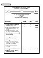
FINAL EXAM – DISTRIBUTED SYSTEMS CSE486/586
December 12, 2003 (Fall 2003)
NAME : _____________________________________________________________
STUDENT NUMBER : _________-_________
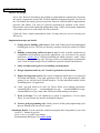
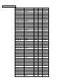
INSTRUCTIONS
This is a closed book but you are allowed two sheets of information to refer to. You have 180
minutes to complete 10 questions. Please write neatly and clearly. To receive partial credit, you
must show all work for your answers. You should have 11 pages in this exam book, some of
which are blank to allow room for your answers.
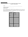
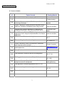
Question
I
II
III.1
2.
3.
4.
5.
6.
7.
8.
9.
10.
11.
12.
Total
Grade
____/20
____/20
____/100
A-PDF MERGER DEMO
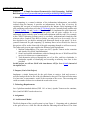
I. (20 points) Design of a Grid Service
A business process is a fundamental component of a business system. In order for a grid
service to be used to support business applications, it should be possible to model a
business process as a grid service. Show the feasibility of this claim.
Hints:
• Examples for business process: Inventory control, Order Management, and
Billing.
• Define a business process, list its requirements.
• Then identify the grid services capabilities that will satisfy the requirements. The
capabilities of a grid service discussed in the GT3 tutorial will help.
• Bring all these together as an application implementing the business process.
2
A-PDF MERGER DEMO
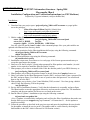
II. (20 points) Design and Implementation of grid-based application
An e-commerce site is a very common application used in discussing large scale multitier distributed systems. An example of an e-commerce site is amazon.com. Explain with
diagrams, the requirements of such an application and how it can be implemented using
specific features of the grid computing framework.
Hint: You may have to use VO, virtualization and other such system level concepts.
3
A-PDF MERGER DEMO
III. Answer the following questions using few sentences. Assume Grid computing
context for all the questions. Each question is worth 5 points. A good answer would
have a simple explanation, an example and a diagram.
1. What is meant by virtualization?
2. What is a virtual organization (VO)?
3. What is federation of information?
4. What are the two approaches to designing a grid service?
5. Describe a Grid Service-based Application model. Use a block diagram.
6. What is the difference between transient and persistent services?
7. What is a portType?
8. What is a service EndPoint?
9. What is a service data? How can it be used by applications?
10. What is Notification? How can be used by applications?
11. What is a (i) Facory and (ii) Registry? How are they related?
12. What is a service handle, service reference and a handleMap? How are they related?
4
A-PDF MERGER DEMO
DRAFT - Nov 16, 2003
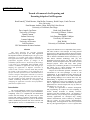
Course Evaluation
CSE 486: Distributed Systems
This course evaluation is part of an effort to evaluate the courses that are being developed as
part of a grant from the National Science Foundation. Your participation in this course
evaluation will provide important information to help improve the course. In addition, your
comments will benefit students taking this course in the future.
We appreciate your taking the time to read each question carefully and answer them as fully as
possible.
Instructions for Completing the Course Evaluation
• Do not put your name on any form. Survey responses will remain anonymous.
• Please respond to items 1–35 on this survey by circling the appropriate number.
Responses to items 36–39 should be reported in the spaces provided.
• When you have completed the survey, please place the forms in the envelope supplied by
your instructor.
1
A-PDF MERGER DEMO
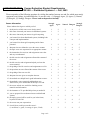
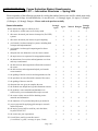
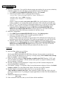
Course Evaluation Student Questionnaire
CSE 486 — Distributed Systems I — Fall, 2003
Please respond to of the following questions by circling the number between one and five which most nearly
represents your feelings. As indicated below, we use the scale: (1) Strongly Agree, (2) Agree, (3) Neutral,
(4) Disagree, (5) Strongly Disagree. Please read each question carefully.
Strongly
Agree
Agree
1. the objectives of this course were clearly stated.
1
2
3
4
5
2. this course increased your interest in distributed systems.
1
2
3
4
5
3. this course increased your interest in grid computing.
1
2
3
4
5
4. you learned a lot about distributed systems, including both
concepts and implementation.
1
2
3
4
5
5. you learned a lot about grid computing and its future
potential.
1
2
3
4
5
6. adequate time was allotted to cover the course content.
1
2
3
4
5
7. the topic areas were sequenced in an appropriate manner.
1
2
3
4
5
8. the instructions for exercises and assignments were clear
and easy to understand.
1
2
3
4
5
9. the lab exercises and assignments reflected the content of
the course.
1
2
3
4
5
10. the lab exercises and assignments helped you learn the
course material.
1
2
3
4
5
11. the grading of the lab exercises and assignments was fair.
1
2
3
4
5
12. the questions on tests reflected the content of the course.
1
2
3
4
5
13. the grading of the tests was fair.
1
2
3
4
5
14. adequate time was given to complete the tests.
1
2
3
4
5
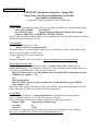
15. the textbook was helpful and a good information resource.
1
2
3
4
5
16. the textbook, course materials and handouts were
sufficient for you to understand all the topics covered.
1
2
3
4
5
17. the course website was useful for obtaining course
materials and information.
1
2
3
4
5
18. the instructor or TA provided help when you needed it.
1
2
3
4
5
19. you are prepared for an advanced course on distributed
systems.
1
2
3
4
5
20. the topics covered will be useful to you in the future,
beyond CSE 486-586.
1
2
3
4
5
21. the course met your expectations.
1
2
3
4
5
22. Overall, how would you rate this course?
(1=excellent, 2= good, 3=average, 4=poor, 5=bad)
1
2
3
4
5
Course Information
Please indicate the degree to which you feel
Page 1 of 3
Neutral Disagree
Strongly
Disagree
2
A-PDF MERGER DEMO
Strongly
Agree
Agree
23. understand the fundamental components and operation of
a distributed system.
1
2
3
4
5
24. can design and implement a distributed application.
1
2
3
4
5
25. are able to analyze a distributed system for its architecture,
algorithms, protocols and services.
1
2
3
4
5
26. have good understanding and working knowledge of
grid computing.
1
2
3
4
5
27. are able to program using Web services.
1
2
3
4
5
28. are able to program using the Globus grid computing
framework.
1
2
3
4
5
29. are able to demonstrate the ability to design, implement,
and deploy distributed systems based on Java technology
and Grid Technology.
1
2
3
4
5
Strongly
Agree
Agree
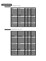
30. the type of hardware computer resources provided by UB
were appropriate for the course.
1
2
3
4
5
31. the type of software computer resources provided by UB
were appropriate for the course.
1
2
3
4
5
32. the computer resources provided by UB were adequate to
do the lab exercises and assignments.
1
2
3
4
5
33. the computer resources were available and accessible
when you needed or wanted to use them.
1
2
3
4
5
34. the computer resources enabled you to gain "hands on"
experience with distributed systems.
1
2
3
4
5
35. the computer resources enabled you to gain "hands on"
experience with grid computing.
1
2
3
4
5
Course Objectives
Please indicate the degree to which you feel you
Computer Resources (Hardware and Software)
Please indicate the degree to which you feel
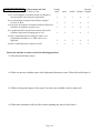
Please take the time to answer each of the following questions.
36. Why did you take this course?
Page 2 of 3
Neutral Disagree
Neutral Disagree
Strongly
Disagree
Strongly
Disagree
3
What wasDEMO
the most valuable aspect of the Distributed Systems course? What did you like about it?
A-PDF37.
MERGER
38. What was the poorest aspect of the course? In what ways could this course be improved?
39. What other comments would you like to make regarding any aspect of this course?
Page 3 of 3
A-PDF MERGER DEMO
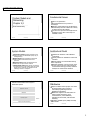
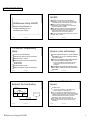
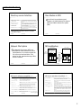
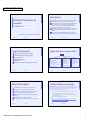
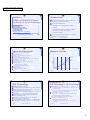
Fundamental Issues
System Models and
Networking
Chapter 2,3
There is no global time.
All communications are by means of
messages.
Message communication may be affected by
network delays and can suffer from a variety
of failures and security attacks.
How does one express a solution/process for
handling an issue? One of the ways is to
establish a model.
Bina Ramamurthy
9/12/2003
B.Ramamurthy
1
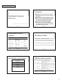
System Models
B.Ramamurthy
3
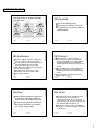
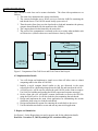
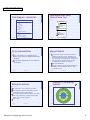
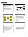
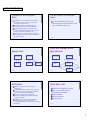
Software and hardware service layers in
distributed systems
Middleware
Operating system
Platform
Computer and network hardware
B.Ramamurthy
2
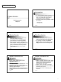
Abstracts the functions of the individual
components.
Defines patterns for distribution of data and
workload.
Defines patterns of communication among
the components.
Example: Definition of server process, client
process and peer process and protocols for
communication among processes; definition
client/server model and its variations.
9/12/2003
B.Ramamurthy
4
Middleware
Applications, services
9/12/2003
B.Ramamurthy
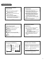
Architectural Model
Interaction model deals with performance and
setting time limits in a distributed system, say, for
message delivery.
Failure model gives specification of faults and
defines reliable communication and correct
processes.
Security model specifies possible threats and
defines the concept of secure channels.
Architectural model defines the way in which the
components of the system interact with one another
and the way in which they are mapped onto the
underlying network of computers.
9/12/2003
9/12/2003
5
Layer of software whose purpose is to mask
the heterogeneity and to provide a
convenient programming model for
application programmers.
Middleware supports such abstractions as
remote method invocation, group
communications, event notification,
replication of shared data, real-time data
streaming.
Examples: CORBA spec by OMG, Java RMI,
MS’s DCOM.
9/12/2003
B.Ramamurthy
6
1
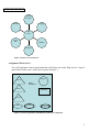
A-PDF MERGER DEMO
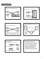
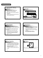
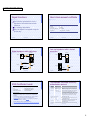
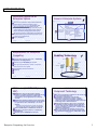
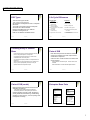
Clients invoke individual servers
A service provided by multiple servers
Service
Client
invocation
Server
Server
invocation
Client
result
Server
result
EX: 1. File server,
2. Web crawler
Server
EX: Web server
Client
Key:
Process:
Computer:
Client
EX: browser,
web client
Server
EX: akamai, altavista, Sun’s NIS (data replication)
9/12/2003
B.Ramamurthy
7
9/12/2003
B.Ramamurthy
8
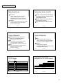
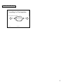
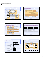
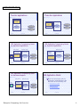
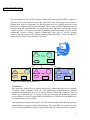
A distributed application based on peer
processes
Web proxy server and caches
Web
server
Client
Proxy
server
Application
Application
Coordination
code
Coordination
code
Web
server
Client
Proxy servers + cache are used to provide increased
Availability and performance. They also play a major role
Firewall based security. http://www.interhack.net/pubs/fwfaq/
9/12/2003
B.Ramamurthy
9
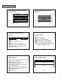
Web applets
9/12/2003
Application
Coordination
code
B.Ramamurthy
10
Networking (Chapter 3)
Distributed systems use local area networks, wide
area networks and internet for communication.
Performance, reliability, scalability, mobility, and
quality of service (qos) impact the design.
Changes in user requirements have resulted in
emergence of wireless and qos guarantees.
Principles: protocol layering, packet switching,
routing, data and behavior streaming.
Coverage: Ethernet, Asynchronous Transfer Mode
(ATM), IEEE 802.11 wireless network standard.
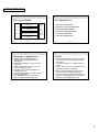
a) client request results in the downloading of applet code
Client
Applet code
Web
server
b) client interacts with the applet
Client
Ex: distributed
Whiteboard
Application;
EJB-based?
Applet
Web
server
EX: Look at Object by value in CORBA
9/12/2003
B.Ramamurthy
11
9/12/2003
B.Ramamurthy
12
2
A-PDF MERGER DEMO
Networking Issues
Networking Issues (contd.)
Performance:
Latency: delays at the switches and routers.
Data transfer rate (bits/sec) : raw data
Bandwidth: total volume of traffic that can be
transferred across the network in a given time.
Scalability:
How does a system handle increase in the number
of users? Increase in the size of the system?
Increase in load and traffic?
9/12/2003
B.Ramamurthy
13
Types of Networks
Single medium such as twisted pair of copper
wires, coaxial cables, or optical fibers.
Technology: Ethernet, token rings, slotted rings.
B.Ramamurthy
15
High bandwidth copper or fiber optic
cables. (phone lines, DSL, cable modem)
Technology: Ethernet, IEEE802.6, ATM
Radio frequency, infrared,
Technology: IEEE 802.11 (wavelan), CDPD,
GSM, bluetooth (proximity)
9/12/2003
B.Ramamurthy
16
Encapsulation in a message
transmitted via TCP over an Ethernet
TCP/IP layers
Layers
14
Wireless:
Set of comm circuits (coax, satellite) linked by
dedicated computers called routers.
Technology: Switching.
9/12/2003
B.Ramamurthy
MAN:
WAN:
9/12/2003
Types of Networks
Characterized by speed, communication
medium, size, geographical distances,
bandwidth, latency, technology.
LAN :
Security: requirements and techniques
for achieving security. Firewall, Virtual
Private Network (VPN).
Mobility: Support for moving devices.
Not necessarily wireless.
QoS: Bandwidth and latency bounds.
Message
Application message
Application
Messages (UDP) or Streams (TCP)
TCP header
Transport
port
IP header TCP
UDP or TCP packets
Internet
Ethernet header IP
IP datagrams
Ethernet frame
Network interface
Network-specific frames
Underlying network
9/12/2003
B.Ramamurthy
17
9/12/2003
B.Ramamurthy
18
3
A-PDF MERGER DEMO
Internet address structure, showing
field sizes in bits
7
24
Network ID
Host ID
Class A:
0
Class B:
1 0
Class C:
1 1 0
Decimal representation of Internet
addresses
octet 1
14
16
Network ID
Host ID
Class A:
8
Network ID
1 to 127
Class C:
128 to 191
192 to 223
Multicast address
1 1 1 1 0
9/12/2003
19
IP packet layout and IPV4
Issues
IP address of destination
data
up to 64 kilobytes
Address limitations
Scarcity of Class B addresses
Managing entries in routing tables
Ad hoc measures such as allocation Class C
to Class B address ranges (CIDR – classless
interdomain routing).
B.Ramamurthy
21
IPV6 Features
1.0.0.0 to
127.255.255.255
0 to 255
0 to 255
0 to 255
128.0.0.0 to
191.255.255.255
0 to 255
Host ID
0 to 255
1 to 254
192.0.0.0 to
223.255.255.255
Class D (multicast):
224 to 239
0 to 255
0 to 255
1 to 254
224.0.0.0 to
239.255.255.255
Class E (reserved):
240 to 255
0 to 255
0 to 255
1 to 254
128.0.0.0 to
247.255.255.255
B.Ramamurthy
9/12/2003
B.Ramamurthy
20
Address limitations
Scarcity of Class B addresses
Managing entries in routing tables
Ad hoc measures such as allocation
Class C to Class B address ranges (CIDR
– classless interdomain routing).
9/12/2003
B.Ramamurthy
22
IPv6 header layout
Addresses are 128 bits (double that of IPV4)
Address space is partitioned
Routing speed improved by removing some
operations such as checksum.
Accommodates real-time and special services.
(streams and devices)
Future evolution possible (next header field).
IPV6 support “anycast” (message delivered to
at least one of the hosts).
Built-in security.
9/12/2003
0 to 255
Host ID
Issues in IPV4
header
9/12/2003
0 to 255
unused
B.Ramamurthy
IP address of source
Range of addresses
Multicast address
27
Class E (reserved):
0 to 255
Network ID
Host ID
28
1 1 1 0
octet 3
Host ID
Network ID
Class B:
21
Class D (multicast):
octet 2
Network ID
23
Version (4 bits)
Priority (4 bits)
Payload length (16 bits)
Flow label (24 bits)
Next header (8 bits)
Hop limit (8 bits)
Source address
(128 bits)
Destination address
(128 bits)
9/12/2003
B.Ramamurthy
24
4
A-PDF MERGER DEMO
Tunnelling for IPv6 migration
IPv6 encapsulated in IPv4 packets
A
IPv6
IPv4 network
IPv6
B
Encapsulators
9/12/2003
B.Ramamurthy
25
5
A-PDF MERGER DEMO
Literature Surveyed
IBM’s alphaworks site:
http://www-106.ibm.com/developerworks/webservices/
Introduction to Web Services
http://www-3.ibm.com/software/solutions/webservices/pdf/WSCA.pdf
Bina Ramamurthy
9/15/2003
1
Web Services is a technology that allows for
applications to communicate with each other
in a standard format.
A Web Service exposes an interface that can
be accessed through XML messaging.
A Web service uses XML based protocol to
describe an operation or the data exchange
with another web service. Ex: SOAP
A group of web services collaborating
accomplish the tasks of an application. The
architecture of such an application is called
Service-Oriented Architecture (SOA).
3
WS Suite of Protocols
A suite of protocols define the Web Services
Technology.
These are used to describe, publish, discover,
deliver and interact with services.
The information about the protocols is from
IBM’s developerworks.
9/15/2003
4
WS Suite of Protocols (contd.)
Messaging protocol Simple Object Access Protocol
(SOAP) encodes messages so that they can be
delivered over the transport protocols HTTP, SMTP or
IIOP.
Web Services Definition Language (WSDL) is used to
specify the service details such as name, methods
and their parameters, and the location of the service.
This facilitates the registering and discovery of the
service.
For services to locate each other, the Universal
Description, Discovery and Integration (UDDI)
protocol defines a registry and associated protocols
for locating and accessing services.
9/15/2003
2
Web Services Suite of
Protocols
Web Services
9/15/2003
9/15/2003
5
The WS-Transaction and WS-Coordination protocols
work together to handle distributed transactions.
The Business Process Execution Language for Web
Services (BPEL4WS) defines workflow operations.
WS-Security is a family of protocols that cover
authentication, authorization, federated security,
secure communications, and delivery.
WS-Policy is another group of protocols that define
the policy rules behind how and when Web services
can interact with each other.
WS-Trust defines how trust models work between
different services.
These protocols are for e-business. Are there any
available for e-science?
9/15/2003
6
1
A-PDF MERGER DEMO
WS Stack
WS Interoperability Infrastructure
Service Flow
WSFL
Service Publication
WSDL
SOAP
Service Description
Management
UDDI
Quality of Service
Service Discovery
Security
UDDI
WSDL
Service Description
SOAP
XML Messaging
HTTP
Network
XML-based Messaging
HTTP, FTP, MQ
Email,9/15/2003
IIOP
Do you see any platform or language dependencies here?
Network
7
JAX-RPC
9/15/2003
Application Architecture
JAX-RPC: Java API for XML-based Remote Procedure
Call (RPC).
An API for building Web Services and Web Services
clients.
Some important concepts in JAX-RPC are:
Type-mapping system (WSDL to Java)
Service endpoint
Exception handling
Service endpoint context
Message handlers
Service clients and service context
SOAP with attachments
Runtime services
JAX-RPC client invocation models
Weather Client
Weather Service
Endpoint impl
JAX-RPC Stub
JAX-RPC Ties
JAX-RPC
Runtime (APIs)
JAX-RPC
Runtime (APIs)
Transport
9/15/2003
9
Approaches to Web Service
Implementation
SOAP/HTTP
Transport
9/15/2003
10
WS Development Lifecycle
Top down: Start with WSDL and map
onto Java
Bottom up: Start with Java and end up
all the supporting classes needed.
We used the second approach for our
RMI example.
Build:
11
Definition of service interface
Definition of service implementation
New services
Existing application into WS
Composing a WS out of other WS and applications
Source compiled and Stubs and Ties are generated.
Deploy:
9/15/2003
8
9/15/2003
Publication of the service interface and service
implementation to service registry or service requestor.
Deployment of executables in an execution environment.
12
2
A-PDF MERGER DEMO
WS Development Lifecycle
(contd.)
A Simple Example from Sun
Microsystem
Run: A WS is available for invocation.
Requestor can perform find and bind
operation.
Manage: on going management and
administration for security, availability,
performance, QoS, and business
processes.
9/15/2003
13
Building and Deploying the
Service
15
ant setup-web-inf
ant package
ant process-war
Will invoke wsdeploy to generate the tie classes and the
WDSL file MyHello.wsdl
To deploy the service:
These two commands will generate and place
the executables in appropriate directories.
(Details will be given to you later in another
handout).
9/15/2003
16
To generate Ties and WSDL:
ant compile-server
To pacakge:
9/15/2003
Generating Ties and WSDL file
and deploy the service
To compile:
14
The interface extends java.rmi.Remote
interface.
No constant declarations allowed.
Methods must throw
java.rmi.RemoteException
Method parameters and return types
must be supported by JAX-RPC types.
Compiling and Packaging
9/15/2003
Coding the interface and
implementation classes
Code the service definition interface
and implementation class.
Compile the service definition code
written above.
Package the code in a WAR (web
archive) file.
Generate the ties and WSDL files.
Deploy the service.
9/15/2003
HelloWorld distributed application:
Files of interest:
HelloIF.java: service definition interface
HelloImpl.java: Service definition implmentation.
HelloClient.java: remote client to invoke the service.
config-interface.xml: configuration file used by
wscompile
jaxrpc-ri.xml: a configuration file used by wsdeploy
web.xml: a deployment descriptor for the web
component that dispatches to the service.
build.xml for running the various steps such as
compile, wscompile, deploy etc. Used by the ant tool.
build.properties: contains the details of varuious
context roots or paths.
17
ant deploy
To verify deployment:
http://localhost:8080/hello-jaxrpc/hello
The details of the web service will be displayed.
To undeploy:
9/15/2003
ant undeploy
18
3
A-PDF MERGER DEMO
Client steps
Building and Running the client
Generate the stubs.
Code the client.
Compile the client code.
Package the client classes into a JAR
file.
Run the client.
9/15/2003
To generate stubs:
Coding the client: is a stand alone
program. It calls the service through
the generated stub which acts as a
proxy for the remote service.
19
Clients steps (contd.)
ant compile-client
ant jar-client
Running the client:
Ant run
9/15/2003
21
Other features
9/15/2003
22
Reading Material
Read about the types supported by
JAX-RPC
An advanced feature of interest is the
dynamic proxy.
Read about the directory structure and
paths.
9/15/2003
20
Test the application.
Edit the source files.
Execute ant build to create and deploy war
files.
Execute ant redeploy to undeploy and deploy
the service.
Execute ant build-static to create jar files with
static stubs.
Execute ant run to run the client.
Package the client:
9/15/2003
Iterative Development
Compile the client code:
ant generate-stubs
This will call wscompile to generate the
stubs.
23
Introduction to Web Services Ch.1.
Building Web Services with JAX-RPC Ch.
11.
Ant build tool details.
XML, XML Schema and SOAP1.1.
9/15/2003
24
4
A-PDF MERGER DEMO
JAX-RPC
JAX-RPC (The Java API for XML-based RPC) is
designed to provide a simple way for developers to
create Web services server and Web services client.
Based on remote procedure calls; so the
programming model is familiar to Java developers
who have used RMI or CORBA.
Major difference between RMI and JAX-RPC is that
messages exchanged are encoded in XML based
protocol and can be carried over a variety of
transport protocols such as HTTP, SMTP etc.
You can use JAX-RPC without having to be an expert
in XML, SOAP, or HTTP.
WebServices Using JAX-RPC
Based on the presentation in
O’Rielly’s Webservices in a
NutShell by Kim Topley
9/26/2003
B.Ramamurthy
1
The JAX-RPC Programming
Model
B.Ramamurthy
3
port2
port3
Other. Ex:
ebXML over
SMTP
Web services Client
https 1.1 transport
soap1.1 messages
9/26/2003
B.Ramamurthy
WebServices Using JAX-RPC
9/26/2003
B.Ramamurthy
4
Web Service Clients and
Servers
endpoint
SOAP 1.1 over
https
A port has an address that the client can use to
communicate with the service and invoke its
operations.
An endpoint can be bound to different ports
each offering a different suite of protocols for
interaction.
Web service
Port1
2
Service endpoint interface or service endpoint
that defines one or more operations that the
web service offers.
Access to an endpoint is provided by binding
it to a protocol stack through a port.
Endpoint, Port and binding
SOAP1.1
Over http
B.Ramamurthy
Services, ports and bindings
Services, ports and bindings
JAX-RPC web service servers and clients
JAX-RPC service creation
JAX-RPC client and server programming
environments
Stubs and ties
Client invocation modes
Static and dynamic stubs and invocation
9/26/2003
9/26/2003
5
JAX-RPC maps a
web service operation to a java method call.
service endpoint to a Java Interface.
Thus one way to begin implementation of a web
service in JAX-RPC is to define a Java interface with a
method for each operation of the service along with a
class that implements the interface. Of course,
following the rules of remote invocation etc.
Now visualize client/server invocation in the same
address space and lets compare it with remote
invocation.
9/26/2003
B.Ramamurthy
6
1
A-PDF MERGER DEMO
Local Date Service
JAX-RPC service creation
//server
public class DataService {
public Data getDate() {
return new Date();}
//client
Public class Appln {
public static void main (..) {
DateService instance = new DateService();
Date date = instance.getDate();
System.out.println (“ The date is” + date);
}
In the case of the remote call a layer of software is used to
convey the method call from client to server. This layer of
software is provided by JAX-RPC runtime.
9/26/2003
A service definition describes the operations that it
provides and the data types that they require as
argument and provide as return values.
This definition can be made available as a document
written in WSDL.
From a WSDL document, JAX-RPC can generate the
Java code required to connect a client to a server
leaving one to write only the logic of the client
application itself.
Since WSDL is language independent the server can
be in .net, Jax-rpc or any other compatible platform.
B.Ramamurthy
7
JAX-RPB service creation
(contd.)
B.Ramamurthy
9
Stubs and Ties
Client application is linked with the stub.
When it invokes a method stub delegates the call to the JAX-RPC runtime
so that appropriate SOAP message can be sent to the server.
On completion the result return back in the reverse path as above.
Server side:
Message received must be converted into a method call on actual service
implementation. This functionality is provided by another piece of glue
called tie.
Tie extracts method name and parameter from SOAP message.
Tie also converts the result of the method call back into a response
message to be returned to client JAX-RPC runtime.
Developer need not write these classes (tie and stub) since JAX-RPC
comes with tools to generate them.
9/26/2003
B.Ramamurthy
WebServices Using JAX-RPC
8
JAX-RPC API is distributed over a set of
packages:
9/26/2003
javax.xml.rpc
javax.xml.rpc.encoding
javax.xml.rpc.handler
javax.xml.rpc.handler.soap
javax.xml.rpc.holders
javax.xml.rpc.server
javac.xml.rpc.soap
B.Ramamurthy
10
Client Invocation Modes
Client Side: Stub object has the same methods as the service
implementation class.
B.Ramamurthy
Client and Server
Programming Environment
Define the service a Java interface.
Generate WSDL using the tools
provided with JAX-RPC package.
Advertise it in a registry for the client to
lookup and import it.
For publication and lookup any other
technology such as J2EE can be used.
9/26/2003
9/26/2003
11
Synchronous request-response mode
(tightly coupled).
One-way RPC (loosely coupled): no
value returned, no exception thrown,
need to bypass stub layer, use Dynamic
Invocation Interface (DII).
9/26/2003
B.Ramamurthy
12
2
A-PDF MERGER DEMO
Client Invocation Modes
9/26/2003
B.Ramamurthy
WebServices Using JAX-RPC
13
3
A-PDF MERGER DEMO
Introduction
Distributed file systems support the sharing
of information in the form of files throughout
the intranet.
A distributed file system enables programs to
store and access remote files exactly as they
do on local ones, allowing users to access
files from any computer on the intranet.
Recent advances in higher bandwidth
connectivity of switched local networks and
disk organization have lead high performance
and highly scalable file systems.
Distributed File Systems
B.Ramamurthy
9/26/2003
B.Ramamurthy
1
Storage systems and their
properties
9/26/2003
B.Ramamurthy
File system modules
Sharing Persis- Distributed
Consistency Example
tence cache/replicas maintenance
Main memory
1
RAM
File system
1
UNIX file system
Directory module:
relates file names to file IDs
File module:
relates file IDs to particular files
Access control module: checks permission for operation requested
Distributed file system
Sun NFS
Web
Web server
File access module:
Distributed shared memory
Ivy (Ch. 16)
Block module:
accesses and allocates disk blocks
Device module:
disk I/O and buffering
Remote objects (RMI/ORB)
1
CORBA
Persistent object store
1
CORBA Persistent
Object Service
Persistent distributed object store
9/26/2003
reads or writes file data or attributes
PerDiS, Khazana
B.Ramamurthy
3
File attribute record structure
9/26/2003
File length
filedes = open(name, mode)
filedes = creat(name, mode)
Read timestamp
Write timestamp
status = close(filedes)
4
Opens an existing file with the given name.
Creates a new file with the given name.
Both operations deliver a file descriptor referencing the open
file. The mode is read, write or both.
Closes the open file filedes.
count = read(filedes, buffer, n) Transfers n bytes from the file referenced by filedes to buffer.
count = write(filedes, buffer, n) Transfers n bytes to the file referenced by filedes from buffer.
Both operations deliver the number of bytes actually transferred
and advance the read-write pointer.
Attribute timestamp
Reference count
Owner
pos = lseek(filedes, offset,
whence)
status = unlink(name)
File type
Access control list (ACL)
status = link(name1, name2)
status = stat(name, buffer)
B.Ramamurthy
B.Ramamurthy
UNIX file system operations
Creation timestamp
9/26/2003
2
5
9/26/2003
Moves the read-write pointer to offset (relative or absolute,
depending on whence).
Removes the file name from the directory structure. If the file
has no other names, it is deleted.
Adds a new name (name2) for a file (name1).
Gets the file attributes for file name into buffer.
B.Ramamurthy
6
1
A-PDF MERGER DEMO
Distributed File System
Requirements
Transparency
Many of the requirements of distributed
services were lessons learned from
distributed file service.
First needs were: access transparency and
location transparency.
Later on, performance, scalability,
concurrency control, fault tolerance and
security requirements emerged and were met
in the later phases of DFS development.
9/26/2003
B.Ramamurthy
7
Concurrent file updates is protected (record
locking).
File replication to allow performance.
Hardware and operating system
heterogeneity.
Fault tolerance
Consistency : Unix uses on-copy update
semantics. This may be difficult to achieve in
DFS.
Security
Efficiency
B.Ramamurthy
B.Ramamurthy
8
The responsibilities of a DFS are typically
distributed among three modules:
Client module which emulates the conventional
file system interface
Server modules(2) which perform operations for
clients on directories and on files.
Most importantly this architecture enables
stateless implementation of the server
modules.
9
File service architecture
Client computer
9/26/2003
General File Service
Architecture
Other Requirements
9/26/2003
Access transparency: Client programs should be
unaware of the the distribution of files.
Location transparency: Client program should see a
uniform namespace. Files should be able to be
relocated without changing their path name.
Mobility transparency: Neither client programs nor
system admin program tables in the client nodes
should be changed when files are moved either
automatically or by the system admin.
Performance transparency: Client programs should
continue to perform well on load within a specified
range.
Scaling transparency: increase in size of storage and
network size should be transparent.
9/26/2003
B.Ramamurthy
10
Flat file service Interface
Server computer
Read(FileId, i, n) -> Data If 1 ≤ i ≤ Length(File): Reads a sequence of up to n items
— throwsBadPosition
from a file starting at item i and returns it in Data.
Write(FileId, i, Data)
If 1 ≤ i ≤ Length(File)+1: Writes a sequence of Data to a
— throwsBadPosition
file, starting at item i, extending the file if necessary.
Create() -> FileId
Creates a new file of length 0 and delivers a UFID for it.
Delete(FileId)
Removes the file from the file store.
GetAttributes(FileId) -> AttrReturns the file attributes for the file.
SetAttributes(FileId, Attr) Sets the file attributes (only those attributes that are not
shaded in ).
Directory service
Application Application
program
program
Flat file service
Client module
Primary operations are reading and writing.
9/26/2003
B.Ramamurthy
11
9/26/2003
B.Ramamurthy
12
2
A-PDF MERGER DEMO
Directory service Interface
Case Studies in DFS
Lookup(Dir, Name) -> FileId
— throwsNotFound
Locates the text name in the directory and returns the
relevant UFID. If Name is not in the directory, throws an
exception.
AddName(Dir, Name, File)
If Name is not in the directory, adds (Name, File) to the
— throwsNameDuplicate
directory and updates the file’s attribute record.
If Name is already in the directory: throws an exception.
UnName(Dir, Name)
If Name is in the directory: the entry containing Name is
— throwsNotFound
removed from the directory.
If Name is not in the directory: throws an exception.
GetNames(Dir, Pattern) -> NameSeqReturns all the text names in the directory that match the
regular expression Pattern.
We will look into architecture and
operation of SUN’s Network File System
(NFS) and CMU’s Andrew File System
(AFS).
Primary purpose is to provide a service for translation
text names to UFIDs.
9/26/2003
B.Ramamurthy
13
Network File System
9/26/2003
B.Ramamurthy
NFS architecture
Client computer
B.Ramamurthy
15
NFS server operations (simplified) – 1
Application Application
program
program
UNIX kernel
UNIX kernel
Virtual file system
Local
UNIX
file
system
9/26/2003
Virtual file system
Remote
NFS
client
NFS
server
NFS
protocol
B.Ramamurthy
UNIX
file
system
16
NFS server operations (simplified) – 2
lookup(dirfh, name) -> fh, attr
Returns file handle and attributes for the file name in the directory
dirfh.
create(dirfh, name, attr) ->
newfh, attr
Creates a new file name in directory dirfh with attributes attr and
returns the new file handle and attributes.
remove(dirfh, name) status
Server computer
UNIX
system calls
Other
file system
The Network File System (NFS) was
developed to allow machines to mount
a disk partition on a remote machine as
if it were on a local hard drive. This
allows for fast, seamless sharing of files
across a network.
9/26/2003
14
symlink(newdirfh, newname, string)Creates an entry newname in the directory newdirfh of type
-> status
symbolic link with the value string. The server does not interpret
the string but makes a symbolic link file to hold it.
readlink(fh) -> string
Returns the string that is associated with the symbolic link file
identified by fh.
Removes file name from directory dirfh.
getattr(fh) -> attr
Returns file attributes of file fh. (Similar to the UNIX stat system
call.)
mkdir(dirfh, name, attr) ->
newfh, attr
Creates a new directory name with attributes attr and returns the
new file handle and attributes.
setattr(fh, attr) -> attr
Sets the attributes (mode, user id, group id, size, access time
modify time of a file). Setting the size to 0 truncates the file.
and
rmdir(dirfh, name) -> status
Removes the empty directory name from the parent directory dirfh.
Fails if the directory is not empty.
readdir(dirfh, cookie, count) ->
entries
Returns up to count bytes of directory entries from the directory
dirfh. Each entry contains a file name, a file handle, and an opaque
pointer to the next directory entry, called a cookie. The cookie is
used in subsequent readdir calls to start reading from the following
entry. If the value of cookie is 0, reads from the first entry in the
directory.
statfs(fh) -> fsstats
Returns file system information (such as block size, number of
free blocks and so on) for the file system containing a file fh.
read(fh, offset, count) -> attr, data Returns up to count bytes of data from a file starting at offset.
Also returns the latest attributes of the file.
write(fh, offset, count, data) -> attr Writes count bytes of data to a file starting at offset. Returns the
attributes of the file after the write has taken place.
rename(dirfh, name, todirfh, toname)Changes the name of file name in directory dirfh to toname in
-> status
directory to todirfh
.
link(newdirfh, newname, dirfh, name)Creates an entry newname in the directory newdirfh which refers to
-> status
file name in the directory dirfh.
Continues on next slide .
9/26/2003
B.Ramamurthy
17
9/26/2003
B.Ramamurthy
18
3
A-PDF MERGER DEMO
Local and remote file systems accessible
on an NFS client
Server 1
Client
(root)
(root)
. . . vmunix
export
people
usr
nfs
Remote
mount
Remote
students
x
NFS Revisited
Server 2
(root)
staff
big jon bob . . .
mount
From A.Tannenbaum’s text
Three aspects of NFS are of interest:
the architecture, the protocol, and the
implementation.
users
jim ann jane joe
Note: The file system mounted at /usr/students in the client is actually the sub-tree located at /export/people in Server
the file system mounted at /usr/staff in the client is actually the sub-tree located at /nfs/users in Server 2.
9/26/2003
B.Ramamurthy
19
NFS Architecture
B.Ramamurthy
21
Mounting
20
One of the goals o NFS is to support a
heterogeneous system, with clients and
servers running different operating systems
on different hardware. It is essential the
interface between clients and server be well
defined.
NFS accomplishes this goal by defining two
client-server protocol: one for handling
mounting and another for directory and file
access.
Protocol defines requests by clients and
responses by servers.
9/26/2003
B.Ramamurthy
22
File Access
Client requests a directory structure to
be mounted, if the path is legal the
server returns file handle to the client.
Or the mounting can be automatic by
placing the directories to mounted in
the /etc/rc: automounting.
9/26/2003
B.Ramamurthy
NFS Protocol
Allows an arbitrary collection of clients and
servers to share a common file system.
In many cases all servers and clients are on
the same LAN but this is not required.
NFS allows every machine to be a client and
server at the same time.
Each NFS server exports one or more
directories for access by remote clients.
See example enclosed.
9/26/2003
9/26/2003
B.Ramamurthy
23
NFS supports most unix operations except
open and close. This is to satisfy the
“statelessness” on the server end. Server
need not keep a list of open connections. See
the operations listed in slides 17, 18.
(On the other hand consider your database
connection… you create an object, connection
is opened etc.)
9/26/2003
B.Ramamurthy
24
4
A-PDF MERGER DEMO
Implementation
Vnode use
After the usual system call layer, NFS specific
layer Virtual File System (VFS) maintains an
entry per file called vnode (virtual I-node) for
every open file.
Vnode indicate whether a file is local or
remote.
For remote files extra info is provided.
For local file, file system and I-node are specified.
Lets see how to use v-nodes using a mount, open,
read system calls from a client application.
9/26/2003
B.Ramamurthy
25
Remote File Access
Distribution of processes in the Andrew
File System
26
When the request message arrives at the NFS
server, it is passed to the VFS layer where
the file is probably identified to be a local or
remote file.
Usually a 8K chunk is returned. Read ahead
and caching are used to improve efficiency.
Cache: server side for disk accesses, client
side for I-nodes and another for file data.
Of course this leads to cache consistency and
security problem which ties us into other
topics we are discussing.
9/26/2003
B.Ramamurthy
28
Summary
Study Andrew Files System (AFS): how?
Architecture
APIs for operations
Protocols for operations
Implementation details
Vice
UNIX kernel
UNIX kernel
Network
Vice
Venus
User
program
UNIX kernel
9/26/2003
B.Ramamurthy
Servers
User Venus
program
Venus
User
program
UNIX kernel
9/26/2003
Server Side of File Access
When a remote file is opened by the client, it
locates the r-node.
It then asks NFS Client to open the file. NFS
file looks up the path in the remote file
system and return the file handle to VFS
tables.
The caller (application) is given a file
descriptor for the remote file. No table entries
are made on the server side.
Subsequent reads will invoke the remote file,
and for efficiency sake the transfers are
usually in large chunks
(8K).
9/26/2003
B.Ramamurthy
27
Workstations
To mount a remote file system, the sys admin
(or /etc/rc) calls the mount program
specifying the remote directory, local
directory in which to be mounted, and other
info.
If the remote directory exist and is available
for mounting, mount system call is made.
Kernel constructs vnode for the remote
directory and asks the NFS-client code to
create a r-node (remote I-node) in its internal
tables. V-node in the client VFS will point to
local I-node or this r-node.
UNIX kernel
B.Ramamurthy
29
9/26/2003
B.Ramamurthy
30
5
A-PDF MERGER DEMO
Introduction
Name Services
Bina Ramamurthy
Chapter 9
You need to name an entity in order to use it.
If you don’t have a name or don’t know a
name you should be able to describe its
characteristics in order to identify it.
According to these two requirements we have
two services:
9/26/2003
9/26/2003
1
Naming Service
3
Names, Attributes and
Addresses
Given a description, find a service or
resource that matches the description.
For example consider the yellow
pages: when you want to rent a car, it
may give a list of car rental agencies.
9/26/2003
4
Names, Attributes and
Addresses
Names: human readable names such as
/etc/passwd, URLs such as
http://www.cd3.net/
An address is an attribute of a name. Ex: castor
is the name, its address is 128.205.34.1
Identifiers: refer to names that are interpreted
by programs. Examples: remote object
reference, NFS file handles.
Name Resolution: a name is resolved when it is
translated into data about the name’s resource
or object.
9/26/2003
2
Directory Service
Given the name of a resource returns the
information about the resource.
For example consider the white pages:
given the name of a person you get the
address/telephone number of that person.
Other examples: LDAP (Lightweight Directory
Access Protocol) a person on UB computers
gives you information about the person’s
email, campus address, phone number,
position held etc.
9/26/2003
Naming service
Directory service
5
Binding: association between a name and an
object. In general, names are bound to the
attributes of the object rather than an
implementation of an object.
Attribute: Value or property of an object.
Names and services: many of the names are
specific to some services.
URL: principle means of identifying web
resources
9/26/2003
6
1
A-PDF MERGER DEMO
Some Familiar Naming
Services
Example
Name: HelloService
URL
DNS: maps domain names to the
attributes of a host computer.
X500 maps person’s name to personal
information.
CORBA naming service maps a name to
remote object reference.
http://gagarin.cse.edu:14566/WSHello/WSInteraction.html
DNS lookup
Resource ID (IP number, port number, pathname)
55.55.55.55
14566 WSHello/WSInteraction.html
Web server
Network address
128.205.36.65
9/26/2003
7
A name service stores a collection of one or more
naming contexts – set of bindings between names and
attributes for objects such as users, computers, services
and remote objects.
Name Management is separated from other services
because of the openness of the distributed system.
Requirements:
Unification (EX: URLs, uniform names, UUID)
Integration: Share resources for resolving names.
Handle arbitrary number of names and domains
Long lifetime, High Availability, Fault isolation,
Tolerance of mistrust
9/26/2003
9
8
Namespace: is a collection of all valid names
recognized by a particular service (context).
Requires syntactic definition.
Can be flat or hierarchical: Hierarchical is
scalable and reusable and can be managed
separately.
May provide aliases for names.
Can be broken down into domains.
9/26/2003
10
Figure 9.2 Name Resolution: Iterative
navigation
Is a repetitive process in which a name is
presented successively to naming contexts
until its context is located or not locatable.
When a context contains the name its
attributes are returned.
Navigation among the contexts can be
iterative or recursive as shown in the next
slides.
9/26/2003
9/26/2003
Name Resolution
file
NameSpaces
Name Service
Socket
NS2
2
Client
1
NS1
Name
servers
3
NS3
A client iteratively contacts name servers NS1–NS3 in order to resolve a name
11
9/26/2003
12
2
A-PDF MERGER DEMO
Figure 9.3 Non-recursive and
recursive server-controlled navigation
2
2
1
client
NS1
4
NS2
NS2
Directory Services
client
3
1
4
NS1
3
5
NS3
NS3
Non-recursive
server-controlled
Recursive
server-controlled
A name server NS1 communicates with other name servers on behalf of a client
Navigation: Process of locating naming data from among more than one
Name server in order to resolve a name. (iterative or multicast navigation)
9/26/2003
13
Jini: A case study
9/26/2003
14
Jini and Name Servers
Jini (Jini Is Not Initials) is Java’s solution to
providing connectivity to services and devices.
It is network-centric computing model as
opposed to network-transparent model offered
by CORBA and other earlier distributed system
models. Software infrastructure that includes
devices must be incredibly robust.
The devices have to support true “plug and
play”.
Devices and services should form spontaneous
communities.
9/26/2003
A more powerful service than naming where
you look up for names using the attributes
than the other way.
Clients can Lookup for services by providing
their attributes rather the name.
A discovery service provides registry and
lookup for spontaneous networking.
Registry is used by server to publish a service
and lookup is used by a client to locate a
service.
Jini does serves the functionality of a name
server. But it is much more than that.
Jini differs from names servers such as LDAP
(Light Weight Directory Access Protocol) or
DNS (Domain Name Service) in two aspects:
15
Services can appear and disappear without much
overhead. Interested parties can be notified when
a service changes.
Jini is self-healing. It accepts partial failures and
has mechanisms for taking care of this.
9/26/2003
16
Five Key Concepts
Jini Services/Devices
1. Discovery
2. Lookup
3. Leasing
4. Remote Events
5. Transactions
Service providers in Jini can be:
1. Pure software component
2. Pure hardware device
3. Combination of the two
For obvious reasons we will consider only
software services.
9/26/2003
17
9/26/2003
18
3
A-PDF MERGER DEMO
Discovery and Lookup
Leasing
Discovery is Jini service that finds
communities on the network to join to
form a spontaneous “federation”.
It basically searches and locates lookup
services of communities.
Lookup service has the details of
services, their location, code, attributes
etc.
9/26/2003
19
Jini Structure
9/26/2003
Discovery
Remote Method Invocation (RMI)
Java Virtual Machine (JVM)
OS and Hardware
21
Lookup
To find and join a group of Jini services
Sends out multicast packet and unicast
packet
Receives RMI reference to a lookup
service where the requested service
may be found.
9/26/2003
22
Summary
Repository of available services.
Stores proxy of object and its attributes.
Proxy can be thin or fat.
Lookup interface: Registration, Access,
Search, Removal
Note: Best way to study a service is
through its interfaces.
9/26/2003
20
Discovery
Lookup
9/26/2003
Leasing is the technique that provides the
self-healing characteristic of Jini.
Every service provider keeps renewing its
lease with the holder of the services
(probably a lookup service) periodically. If it
fails to update lease the service will be
deleted from the community.
This automatically removes failed or crashed
server from the network thus carrying out the
self-healing.
Other Services
Javaspaces
Jini
23
We studies the essential features of a Name
Service.
We also looked at some existing name
servers.
Jini extends the concepts of a simple name
service to build a spontaneous networking
distributed system model.
Think about: How will you build a
sophisticated name service using the common
name service and the web services
infrastructure?
9/26/2003
24
4
A-PDF MERGER DEMO
Introduction
There are two main issues:
Authentication
Authorization
Authentication: is validating the user and the
messages sent by by the authenticated user.
Authorization: refers to access control of resources
after a user/message has been authenticated.
Security primarily refers to the authentication issue.
This is discussed quite nicely in chapter 7 of your
text.
For access control models we will discuss Java
Authentication and Authorization Service (JAAS).
Security
Chapter 7
9/29/2003
B.Ramamurthy
1
Cryptography is the basis for authentication of messages.
We need security protocols to exploit it.
Selection of cryptographic algorithms and management of keys
are critical issues for effectiveness, performance and usefulness
of security mechanisms.
Public-key cryptography is good for key distribution but
inadequate for encryption of bulk data.
Secret-key cryptography is suitable for bulk encryption tasks.
Hybrid protocols such as SSL (Secure Socket Layer) establish a
secure channel using public-key cryptography and then use it
exchange secret keys for subsequent data exchanges.
B.Ramamurthy
3
1965-75
1975-89
Platforms
Multi-user
timesharing
computers
Distributed systems The Internet, wide- The Internet + mobile
based on local
area services
devices
networks
Shared
resources
Memory, files
Local services (e.g. Email, web sites,
Distributed objects,
NFS), local networksInternet commerce mobile code
9/29/2003
1990-99
Current
Security
User identification and
Protection of servicesStrong security for Access control for
requirements authentication
commercial
individual objects,
transactions
secure mobile code
Security
Single authority,
Single authority,
Many authorities,
management single authorization delegation, replino network-wide
environment database (e.g. /etc/ cated authorization authorities
passwd)
databases (e.g. NIS)
9/29/2003
Most schemes include algorithms for
encrypting and decrypting messages
based on secret codes called keys.
Two common models:
2
Per-activity
authorities, groups
with shared
Responsibilities,
mass authentication
B.Ramamurthy
4
Familiar names for the protagonists
in security protocols
Encryption
B.Ramamurthy
Historical context: the evolution of
security needs
Cryptography
9/29/2003
9/29/2003
Alice
Shared secret keys
Public/private key pairs: A message
encrypted with the public key of the
receiver can be decrypted only by the
private key of the recipient.
B.Ramamurthy
5
9/29/2003
First participant
Bob
Second participant
Carol
Participant in three- and four-party protocols
Dave
Participant in four-party protocols
Eve
Eavesdropper
Mallory
Malicious attacker
Sara
A server
B.Ramamurthy
6
1
A-PDF MERGER DEMO
Cryptography notations
Cryptographic Algorithms
KA
Alice’s secret key
KB
Bob’s secret key
KAB
Secret key shared between Alice and Bob
KApriv
Alice’s private key (known only to Alice)
KApub
Alice’s public key (published by Alice for all to read)
{M}K
MessageM encrypted with keyK
[M]K
MessageMsigned with keyK
9/29/2003
B.Ramamurthy
Plain text Æ cipher textÆ Decipher text
E(K,M) = {M}K where E is the encryption
function, M is the message and K is the key.
Decryption:
D(K,E(K,M)) = M
Same key is used in encrypting and
decrypting. So it is called symmetric
cryptography.
7
Stream cipher
number
generator
n+2
E(K, M)
n+1
buffer
XOR
ciphertext
stream
plaintext
stream
9/29/2003
B.Ramamurthy
9
TEA Encryption Function
unsigned long y = text[0], z = text[1];
unsigned long delta = 0x9e3779b9, sum = 0; int n;
for (n= 0; n < 32; n++) {
sum += delta;
y += ((z << 4) + k[0]) ^ (z+sum) ^ ((z >> 5) + k[1]);
z += ((y << 4) + k[2]) ^ (y+sum) ^ ((y >> 5) + k[3]);
}
9/29/2003
8
Shannon’s principles of cryptography:
introduce “confusion” (XORing, bit shifting
etc.) and “diffusion” (adding noise bits to
diffuse the information)
We will look at Tiny Encryption Algorithm
(TEA) as an example of symmetric algorithm
and Rivest, Shamir and Adelman (RSA) an an
example for asymmetric algorithms.
9/29/2003
B.Ramamurthy
10
TEA decryption function
void encrypt(unsigned long k[], unsigned long text[]) {
text[0] = y; text[1] = z;
B.Ramamurthy
Cryptographic algorithms
keystream
n+3
9/29/2003
void decrypt(unsigned long k[], unsigned long text[]) {
unsigned long y = text[0], z = text[1];
unsigned long delta = 0x9e3779b9, sum = delta << 5; int n;
for (n= 0; n < 32; n++) {
z -= ((y << 4) + k[2]) ^ (y + sum) ^ ((y >> 5) + k[3]);
y -= ((z << 4) + k[0]) ^ (z + sum) ^ ((z >> 5) + k[1]);
sum -= delta;
}
text[0] = y; text[1] = z;
}
}
B.Ramamurthy
11
9/29/2003
B.Ramamurthy
12
2
A-PDF MERGER DEMO
TEA in use
RSA Encryption
void tea(char mode, FILE *infile, FILE *outfile, unsigned long k[]) {
/* mode is ’e’ for encrypt, ’d’ for decrypt, k[] is the key.*/
char ch, Text[8]; int i;
while(!feof(infile)) {
i = fread(Text, 1, 8, infile);
/* read 8 bytes from infile into
Text */
if (i <= 0) break;
while (i < 8) { Text[i++] = ' ';} /* pad last block with spaces */
switch (mode) {
case 'e':
encrypt(k, (unsigned long*) Text); break;
case 'd':
decrypt(k, (unsigned long*) Text); break;
}
fwrite(Text, 1, 8, outfile);
/* write 8 bytes from Text to
outfile */
}
9/29/2003
B.Ramamurthy
13
}
RSA Encryption (contd.)
Application of RSA
To encrypt text using the RSA method, the plaintext is divided into equal blocks of
length k bits where 2k < N (that is, such that the numerical value of a block is always
less than N; in practical applications, k is usually in the range 512 to 1024).
k = 7, since 27 = 128
The function for encrypting a single block of plaintext M is: (N = P X Q = 13X17 =
221), e = 77, d = 5:
E'(e,N,M) = Me mod N
for a message M, the ciphertext is M77 mod 221
The function for decrypting a block of encrypted text c to produce the original
plaintext block is:
D'(d,N,c) = cd mod N
The two parameters e,N can be regarded as a key for the encryption function, and
similarly d,N represent a key for the decryption function.
So we can write Ke = <e,N> and Kd = <d,N>, and we get the encryption function:
E(Ke, M) ={M}K (the notation here indicating that the encrypted message can be
decrypted only by the holder of the private key Kd) and D(Kd, ={M}K ) = M.
B.Ramamurthy
15
How can you authenticate
“sender”?
E(B,E(M,a))
Buffalo will first decrypt using its private key
and use Atlanta’s public key to decrypt the
signed message:
9/29/2003
9/29/2003
E(p, E(M,P)) Æ M
E(P, E(M,p)) Æ M
B.Ramamurthy
16
Digital Signatures
(In real life you will use signatures: the
concept of signatures is introduced.)
Instead of sending just a simple message,
Atlanta will send a signed message signed by
Atlanta’s private key:
Lets say a person in Atlanta wants to send a
message M to a person in Buffalo:
Atlanta encrypts message using Buffalo’s
public key B Æ E(M,B)
Only Buffalo can read it using it private key b:
E(p, E(M,B)) Æ M
In other words for any public/private key pair
determined as previously shown, the
encrypting function holds two properties:
<e,N> - public key, d – private key for a station
9/29/2003
To find a key pair e, d:
1. Choose two large prime numbers, P and Q (each greater than 10100), and
form:
N=PxQ
Z = (P–1) x (Q–1)
2. For d choose any number that is relatively prime with Z (that is, such that d
has no common factors with Z).
We illustrate the computations involved using small integer values for P
and Q:
P = 13, Q = 17 –> N = 221, Z = 192
d=5
3. To find e solve the equation:
e x d = 1 mod Z
That is, e x d is the smallest element divisible by d in the series Z+1, 2Z+1,
3Z+1, ... .
e x d = 1 mod 192 = 1, 193, 385, ...
385 is divisible by d
9/29/2003
B.Ramamurthy
14
e = 385/5 = 77
Strong digital signatures are essential
requirements of a secure system. These are
needed to verify that a document is:
Authentic : source
Not forged : not fake
Non-repudiable : The signer cannot credibly
deny that the document was signed by them.
E(b, E(B,E(M,a)) Æ E(M,a)
E(A,E(M,a)) Æ M
B.Ramamurthy
17
9/29/2003
B.Ramamurthy
18
3
A-PDF MERGER DEMO
Digest Functions
Alice’s bank account certificate
Are functions generated to serve a
signatures. Also called secure hash
functions.
It is message dependent.
Only the Digest is encrypted using the
private key.
9/29/2003
B.Ramamurthy
1. Certificate type
:
2. Name:
3. Account:
4. Certifying authority
:
5. Signature
:
19
M
9/29/2003
B.Ramamurthy
signed doc
H(M)
h
M
E(Kpri, h) {h}Kpri
signed doc
H(M+K)
Signing
M
128 bits
20
Low-cost signatures with a shared
secret key
Digital signatures with public keys
Signing
Account number
Alice
6262626
Bob’s Bank
{Digest(field 2 + field 3)}
KBpriv
h
M
K
{h}Kpri
Verifying
D(Kpub,{h})
h'
M
h
M
h = h'?
H(doc)
Verifying
h
h = h'?
K
9/29/2003
B.Ramamurthy
21
9/29/2003
B.Ramamurthy
Subject
Distinguished Name, Public Key
Header
Message
Issuer
Distinguished Name, Signature
1. A->S:
A, B, NA
Period of validity
Not Before Date, Not After Date
Administrativeinformation
Version, Serial Number
2. S->A:
Extended Information
Certificates are widely used in e-commerce to authenticate
Subjects.
A Certificate Authority is a trusted third party, which certifies
Public Key's do truly belong to their claimed owners.
Certificate Authorities: Verisign, CREN (Corp for Educational
Research Networking), Thawte
See also Netscape SSL2.0 Certificate format:
22
A requests S to supply a key for communication
with B.
S returns a message encrypted in A’s secret key,
{NA , B, KAB,
containing a newly generated key K and a
{KAB, A}KB}KA ‘ticket’ encrypted in B’s secret key. AB
The nonce NA
demonstrates that the message was sent in response
to the preceding one. A believes that S sent the
message because only S knows A’s secret key.
A sends the ‘ticket’ to B.
4. B->A: {NB}KAB
B decrypts the ticket and uses the new key KAB to
encrypt another nonce NB.
5. A->B:
23
Notes
3. A->B: {KAB, A}KB
http://wp.netscape.com/eng/security/ssl_2.0_certificate.html#SSL2cert
B.Ramamurthy
h'
The Needham–Schroeder secret-key
authentication protocol
X509 Certificate format
9/29/2003
H(M+K)
9/29/2003
{NB - 1}KAB
A demonstrates to B that it was the sender of the
previous message by returning an agreed
transformation of NB.
B.Ramamurthy
24
4
A-PDF MERGER DEMO
System architecture of Kerberos
SSL protocol stack
Kerberos Key Distribution Centre
Step A
1. Request for
TGS ticket
Authentication
service A
Authentication
database
SSL
Handshake SSL Change SSL Alert
Cipher Spec Protocol
protocol
Ticketgranting
service T
2. TGS
ticket
Client
C
HTTP Telnet
SSL Record Protocol
Step B
3. Request for
server ticket
4. Server ticket
Login
session setup
Server
session setup
Transport layer (usually TCP)
Step C
5. Service
request
Request encrypted with session key
DoOperation
Service
function
Network layer (usually IP)
Server
S
SSL protocols:
Reply encrypted with session key
9/29/2003
B.Ramamurthy
25
SSL handshake protocol
9/29/2003
B.Ramamurthy
26
SSL handshake configuration options
Establish protocol version, session ID,
cipher suite, compression method,
exchange random values
ClientHello
ServerHello
Certificate
ServerHelloDone
Certificate
Component
Description
Example
request client certificate
Key exchange
method
the method to be used for
exchange of a session key
RSA with public-key
certificates
S end client certificate response if
Cipher for data the block or stream cipher to beIDEA
transfer
used for data
Optionally send server certificate and
Certificate Request
Client
Other protocols:
Server
requested
Certificate Verify
Message digest for creating message
SHA
function
authentication codes (MACs)
Change Cipher Spec
Change cipher suite and finish
handshake
Finished
Change Cipher Spec
Finished
9/29/2003
B.Ramamurthy
27
SSL record protocol
9/29/2003
B.Ramamurthy
Millicent architecture
abcdefghi
Application data
Vendor
Fragment/combine
Record protocol units
28
abc
def
Purchase(item name,
scrip payment)
Customer
Validator
ghi
Master Spent
scrip
scrip
secrets list
Compress
Compressed units
Master
customer
secrets
Hash
MAC
Encrypt
Encrypted
Browser
Completion(item,
scrip change)
scrip
Scrip
store
Customer
secret
Optional secure channel
based on customer secret
Scrip layout
Transmit
Vendor Value Scrip ID Customer ID Expiry date Properties
TCP packet
9/29/2003
B.Ramamurthy
29
9/29/2003
B.Ramamurthy
Certificate
30
5
A-PDF MERGER DEMO
Reference Material
Grid Computing, Making the Global
Infrastructure a Reality by F. Berman, G.
Fox and A. Hey, Wiley and Sons Ltd.,
2003, ISBN: 0-470-85319-0
Publications from the site:
Grid Technology
B. Ramamurthy
10/10/2003
B.Ramamurthy
1
http://www.globus.org/research/papers.html
10/10/2003
Introduction
The Grid
The Grid
The History
Building blocks of the global grid
Layered Grid Model
Grid Applications
Categories of applications
Future of Grid
10/10/2003
B.Ramamurthy
3
History of the Grid
B.Ramamurthy
2
The grid is a a computing and data management
infrastructure that provides us ability to
dynamically link together resources to support
execution of large-scale, resource-intensive, and
distributed applications. (paraphrased from Fran
Berman et al’s text)
Grids are intrinsically distributed, heterogeneous
and dynamic.
10/10/2003
B.Ramamurthy
4
Building Blocks
1980s parallel computing was used as a means of
achieving high performance. Examples: Parallel virtual
Machine (PVM), Message Passing Interface (MPI), and
High Performance Fortran (HPF).
1990s the focus shifted into coordination, distribution and
collaboration, the fundamentals concepts of grid
computing.
I-Way, the precursor modern day grid was demonstrated
in the year 1995 in SC conference.
This lead to the development of
grid software in Globus, Condor, Legion, and others
services such as Network Weather Service (NWS),
Storage Resource Broker (SRB)
Protocols such as Open Grid Services Architecture
(OGSA), Grid Security Infrastructure (GSI)
10/10/2003
B.Ramamurthy
5
Networks: grids are built on ubiquitous highperformance networks such as Internet2 Abilene, and
intra-Europe GEANT network. Networks connect
resources on the grid, such as the computers (nodes)
and the storage.
Computational nodes: Nodes are high performance
parallel machines or clusters.
Infrastructure software: This focuses on pulling
together the network and the nodes and provides a
development environment and execution platform for the
applications.
Standards: Development of key standards is critical for
the successful management of the grid complexity.
OGSA that provides the standard for the services on the
grid is a fine example of such an effort.
10/10/2003
B.Ramamurthy
6
1
A-PDF MERGER DEMO
The Layered Model
Grid applications
New Devices
User-focused grid middleware, tools,
and services
Sensors
Wireless
Common infrastructure layer
(NMI, GGF standards, OGSA etc.)
Grid Applications
Life science Applications
Engineering-oriented applications
Data-oriented applications
Physical science applications
E-science collaboratory
Commercial applications
Common
Policies
Grid
Economy
Global
Area
Networking
Global resources
10/10/2003
B.Ramamurthy
7
Categories of applications
Minimal communication applications:
embarrassingly parallel applications. Ex;
SETI@home
Staged/linked application: access to remote
instruments
Adaptive applications: run where you find
resources satisfying criteria.
Real- time and on
- demand application: do
something right now.
Coordinated applications: dynamic and brand
and bound applications
Poly- applications: choice of resources for
different components of the application.
10/10/2003
B.Ramamurthy
10/10/2003
B.Ramamurthy
8
Trends
9
Development of models of interaction between
users and grid: Grid Computing environments
and portals
Access technologies: non
- computer means of
access.
Policies: grid resources are in different domains.
Developing policies is a challenge.
Grid economies: Building a business model
around it is another interesting challenge.
Grid will serve as the enabling technology for a
broad set of applications in science, business,
entertainment, health and other areas.
10
10/10/2003
B.Ramamurthy
2
A-PDF MERGER DEMO
Introduction
From Prototype to
Production Grid
z
In the last lectures we looked at the design of a prototype
test bed for the grid based on the paper
•
z
http://www-library.lbl.gov/docs/LBNL/511/92/PDF/LBNL51192.pdf
This lecture we will look into the details of transition from
the test bed to a production grid.
B. Ramamurthy
10/22/2003
B.Ramamurthy
1
z
Issue host certificates for all the computing and data
resources and establish procedures for installing them.
Issue user certificates.
You may revoke the certificates to make sure of the
operations and reissue them.
Using certificates issued by your CA validate correct
operation of GSI, GSS libraries, GSISSH and GSIFTP
and/or GRIDFTP at all sites.
Read: Certification Systems:X.509,CA, PGP at
http://mcg.org.br/cert.htm
Another URL to look at to get an overall picture:
z
http://www-library.lbl.gov/docs/LBNL/511/92/PDF/LBNL-51192.pdf
z
z
z
z
10/22/2003
B.Ramamurthy
z
z
2
B.Ramamurthy
Boundaries are primarily defined by:
• Interoperability of the grid software
• What CAs you must trust: This is explicitly
•
configured in each Globus environment on
per CA basis.
How you scope the searching of the GIS or
control the information that is published in
them. It depends on the model you choose to
structure your directory services.
10/22/2003
B.Ramamurthy
4
Local Authorization
GIIS (Resource Information Servers) and
directory servers are needed.
Use a X.500 style hierarchical name
component space directory structure. VO roots
can be attached to the hierarchy extending the
scope.
Index server directory structure: Use Globus
MDS for information directory hierarchy.
10/22/2003
z
3
Model of the GIIS
z
B.Ramamurthy
Defining and Understanding the
Extent of the Grid
First steps
z
10/22/2003
5
z
z
A Globus mapfile is an ACL that maps
from Grid identities to local user
identification numbers (UIDs) on the
systems where jobs are to be run.
A Globus Gatekeeper replaces the usual
login authorization mechanism for Gridbased access and uses mapfile to
authorize access to resources after
authentication.
10/22/2003
B.Ramamurthy
6
1
A-PDF MERGER DEMO
High Performance
Communication Issue
Site Security Issue
z
z
z
Any distributed application requires use of
many IP communication ports. If the server is
behind firewall these ports may not be
accessible. Typical application may require
several 10s of ports.
Globus can be configured to use mid-700
range ports and make sure the sysadmin
knows about the block usage.
Proxies can help manage intra-service
component communication.
10/22/2003
B.Ramamurthy
z
z
z
z
B.Ramamurthy
z
B.Ramamurthy
8
B.Ramamurthy
z
z
z
z
z
Identify some sample problems to test the
working of the grid.
Read a sample “Quick Start Guide” available at
http://www.globus.org/toolkit/documentation/Q
uickStart.pdf
At this point Globus, GIS/MDS, security
infrastructure should all be operational.
Deploy and build Globus on at least two
production platforms at two different facilities.
Configure job submission and schedulers and
verify them.
10/22/2003
B.Ramamurthy
10
Summary
Establish a model for moving data> For
example: GridFTP.
Check the operation using a sample
service such as MyProxy service:
provides for creating and storing
intermediate lifetime proxies that can
accessed by Web-based portals, job
schedulers, and so forth.
10/22/2003
10/22/2003
9
Grid Service Model
z
If high data rate distributed applications
are anticipated, enlist the help of WAN
networking people to refine network
bandwidth end-to-end using large packet
size data streams.
Network monitors and Loggers can help
in monitoring and identifying low rate
problems.
Preparing for the Deployment
Job initiation and resource management are very
important functions closer to the application level.
Parallel Batch Scheduler (PBS) , Condor-G are
examples of schedulers.
PBS provides time-of-the-day based advanced resource
reservation.
Schedulers also maintain queues and implement access
control.
PBS also has full preemption capabilities that combined
with existing access control mechanisms can provide full
disaster response or scheduling of high priority job
preempting a lower priority one.
10/22/2003
z
7
Batch Schedulers
z
z
11
z
z
z
We outlined the installation of prototype
grid.
We also sketched the details of moving
from a prototype grid to a production
grid.
Your task is to read the main paper and
the related material referenced in the
presentation.
10/22/2003
B.Ramamurthy
12
2
A-PDF MERGER DEMO
Globus User’s Guide and Programmer’s Guide:
1. User’s guide tells you about the software and tools needed and how to install,
configure and verify these.
2. Programmer’s guide goes through the details of designing a service and
implementing it.
a.
b.
c.
d.
Provide service interface
Generate Grid service support code
Implement the service
Deploy the service
More Details:
a. Provide service interface:
Two approaches:
interface in Java Æ generate WSDL interface
WSDL portType interfaceÆ generate SOAP binding (Define it in gwsdl)
(PortType is an element defined in WSDL that defines a set of operation and the
messages needed for the operations).
b. Generate Grid Service Support Code:
--All the tools for stub and support code generation are centered around
generateWSDL and generateStubs.
--Ant task and xml batch files are provided to generate the required stub and code
for hosting the service as an OGSI compliant Grid Service.
Bottom up:
--used when the service is available as legacy code in Java and we want to grid
enable it.
Top down:
-- Used when service is in available in someother language other than Java and
you want a Java implementation. Or when when a new grid service is defined.
-- From GWSDL interface: Use GWSLD2WSDL tool to generate WSDL 1.1
portType, run generateBinding tool to generate wsdl:binding and wsdl:service
parts for the portType definition; generateStubs for generating stubs.
c. Implement the service:
--See the Figure 2 Server Programming Model we discussed in the core white
paper.
-- Two approaches: Inheritance approach and Operation provider approach.
--Inheritance extends GridServiceImpl but is tightly coupled with the
implementations in the container.
A-PDF MERGER DEMO
-- Operation Provide approach makes it easy to plug in various implementations at
deployment time.
-- OGSI defined implementations of NotificationSource and Factory have
been implemented as OperationProviders in the framework. These can be
readily configured into the service using deployment descriptors.
-- QName : Qulaified name: conatins namespace and a name as in wsdl.
-- * specifies all operations in a certain namespace
d. Deploy the service:
--write a deployment descriptor configuring your service
-- create a “gar” package of the configuration along with your implementation
-- deploy the gar package into a Grid service hosting env: from OGSA installation
directory run the deploy command.
e. Writing a client
1. Get OGSiGridServiceLocator
2. Resolve GridServiceFactory
3. Resolve CounterServiceGridLocator
4. Make proxy/stub
5. Invoke operation on stub
A-PDF MERGER DEMO
Toward a Framework for Preparing and
Executing Adaptive Grid Programs
Ken Kennedyα, Mark Mazina, John Mellor-Crummey, Keith Cooper, Linda Torczon
Rice University
Fran Berman, Andrew Chien, Holly Dail, Otto Sievert
University of California, San Diego
Dave Angulo, Ian Foster
University of Chicago
Dennis Gannon
Indiana University
Lennart Johnsson
University of Houston
Carl Kesselman
USC/Information Sciences Institute
Abstract
This paper describes the program execution
framework being developed by the Grid Application
Development Software (GrADS) Project. The goal of this
framework is to provide good resource allocation for
Grid applications and to support adaptive reallocation if
performance degrades because of changes in the
availability of Grid resources. At the heart of this strategy
is the notion of a configurable object program, which
contains, in addition to application code, strategies for
mapping the application to different collections of
resources and a resource selection model that provides
an estimate of the performance of the application on a
specific collection of Grid resources. This model must be
accurate enough to distinguish collections of resources
that will deliver good performance from those that will
not. The GrADS execution framework also provides a
contract monitoring mechanism for interrupting and
remapping an application execution when performance
falls below acceptable levels.
Introduction
The recently-published volume The Grid: Blueprint
for a New Computing Infrastructure [5] has established a
compelling vision of a computational and information
resource that will change the way that everyone, from
scientist and engineer to business professional, teacher,
and citizen uses computation [5,12]. Just as the Internet
defines fundamental protocols that ensure uniform and
quasi-ubiquitous access to communication, so the Grid
α
Corresponding author: [email protected]
Ruth Aydt, Daniel Reed
University of Illinois, UrbanaChampaign
Jack Dongarra, Sathish Vadhiyar
University of Tennessee
Rich Wolski
University of California, Santa Barbara
will provide uniform access to computation, data, sensors,
and other resources. Grid concepts are being pursued
aggressively by many groups and are at the heart of major
application projects and infrastructure deployment efforts,
such as NASA’s Information Power Grid (IPG) [7], the
NSF PACI’s National Technology Grid [12] and
Distributed Terascale Facility, the NSF’s Grid Physics
Network, and the European Union’s EU Data Grid and
Eurogrid projects. These and many other groups
recognize the tremendous potential of an infrastructure
that allows one to conjoin disparate and powerful
resources dynamically to meet user needs.
Despite the tremendous potential, enthusiasm, and
commitment to the Grid paradigm, as well as the
sophistication of the applications being discussed, the
dynamic and complex nature of the Grid environment
poses daunting challenges. Few software tools exist. Our
understanding of algorithms and methods is extremely
limited. Middleware exists, but its suitability for a broad
class of applications remains unconfirmed. Impressive
applications have been developed, but only by teams of
specialists [3, 4, 5, 6, 8, 9, 11].
Entirely new approaches to software development
and programming are required for Grid computing to
become broadly accessible to ordinary scientists,
engineers, and other problem solvers. In particular, it
must be relatively easy to develop new Grid applications.
Currently applications are developed atop existing
software infrastructures, such as Globus, by developers
who are experts on Grid software implementation.
Although many useful applications have been produced
this way, this approach requires a level of expertise that
A-PDF MERGER DEMO
will make it difficult for Grid computing to achieve
widespread acceptance.
The Grid Application Development Software
(GrADS) Project was established with support from the
NSF Next Generation Software Program to help address
this challenge. In the GrADS vision, the end user should
be able to specify applications in high-level, domainspecific problem-solving languages and expect these
applications to seamlessly access the Grid to find required
resources when needed. Using such environments, users
would be free to concentrate on how to solve a problem
rather than on how to map a solution onto available Grid
resources.
To realize this vision we must solve two fundamental
technical problems. First, we must understand how to
build programming interfaces that insulate the end user
from the underlying complexity of the Grid execution
environment without sacrificing application execution
efficiency. Second, we must provide an execution
environment that automatically adapts the application to
the dynamically-changing resources of the Grid. To
address this second problem, the GrADS project has
designed an execution framework for adaptive Grid
applications. The goal of this paper is to elaborate the
design of this framework and the motivation behind it.
The GrADS Framework
Initial efforts within the GrADS project have
demonstrated the complexity of writing applications for
the Grid and managing their execution. To deal with this
complexity, the GrADS project has adopted a strategy for
program preparation and execution that revolves around
the idea that a program must be configurable to run on the
Grid. To be configurable in the sense intended by GrADS,
a program must contain more than just code—it must also
include a portable strategy for mapping the program onto
distributed computing resources and a mechanism to
evaluate how well that mapped program will run on a
given set of resources. The notion of a configurable
object program is thus at the heart of the GrADS
execution framework. Later in this paper, we will discuss
tools to help construct mapping strategies and
performance models that are part of the configurable
object program. For now, we will simply assume that
these components exist in executable form.
Once a configurable object program, plus input data,
is provided to the GrADS execution system, there must be
a process that initiates the resource selection, launches the
problem run, and sees its execution through to
completion. In the GrADS execution framework, the
Application Manager is the process that is responsible for
these activities—either directly or through the invocation
of other GrADS components or services. In this scenario,
individual GrADS components only need to know how to
accomplish their task(s); the question of when and with
what input or state becomes the Application Manager's
responsibility.
The application launch and execution process is
illustrated in Figure 1. We will step through this process
discussing the role of each component in the execution
launch sequence.
Application Execution Scenario
A Grid user, or a problem solving environment (PSE)
on behalf of the user, provides source code (which may be
annotated with resource selection or run-time behavior
information) or a handle to an existing IR Code object
previously created for the user. This is given to a
component called the Builder, which is the part of the
program preparation system responsible for producing a
configurable object program (COP). An overview of how
the Builder accomplishes its task will be provided in a
later section.
The Builder will construct any required objects and
return a handle to a configurable object program, which
includes the IR Code, the mapping strategy (or Mapper),
and the performance model, which we will refer to as the
Resource Selection Evaluator (RSE). In addition, the
Builder will provide a model of the resource space needed
for execution of the application. This is called an
Application Abstract Resource and Topology (AART)
Model. An AART Model provides a structured method
for encapsulation of application characteristics and
requirements in an input-data-independent way. This
information is in the form of a collection of descriptive
and parametric resource characteristics along with a
description of the topology connecting these resources.
The purpose of the AART Model is to kick-start the
resource selection process and to provide part of the
information needed by the Mapper and the Resource
Selection Evaluator.
Next, the user starts the Application Manager. This
may be a standard GrADS Application Manager or a
specialized manager designed by the user. The
Application Manager needs the handle to the COP, I/O
location information, the problem run size information
(specifically, information to allow calculation of memory
requirements), plus any desired resource selection criteria
and other run-specific parameters desired or required.
The Application Manager retrieves the pieces of the
COP. The AART Model is combined with the problem
run information, resulting in the Resource Selection Seed
Model. This produces the preliminary state necessary for
the Mapper and the Resource Selection Evaluator to start
being useful.
Once these components are available, the application
manager invokes the Scheduler/Resource
A-PDF MERGER DEMO
Figure 1: The GrADS Application Launch and Execution Process
Negotiator (S/RN) and provides it with the Resource
Selection Seed Model. The Scheduler/Resource
Negotiator is the component responsible for choosing
Grid resources appropriate for a particular problem run
based on that run’s characteristics and organizing them
into a proposed virtual machine. In GrADS, the S/RN is
basically an optimization procedure that searches the
space of acceptable resources looking for the best fit
according to the application’s needs as determined by
using the Resource Selection Evaluator as an objective
function.
The Scheduler/Resource Negotiator then invokes the
Grid Information Service to determine the state of Grid
resources and determine what resources are available that
satisfy the characteristics required by the Resource
Selection Seed Model. In other words, the Resource
Selection Seed Model defines a feasible resource space
for application execution. Once sets of feasible sets of
resources are identified, they are organized into a
collection according to the proposed Grid virtual
machine. The Scheduler/Resource Negotiator then
searches the collection of feasible sets of resources to find
the one with the best performance on the given
application, using the Resource Selection Model provided
by the Application Manager as the objective function.
Once a collection of resources has been identified,
the Application Manager begins the launch sequence.
First, it stores state (basically a checkpoint) on the
impending problem run (i.e. application + data) in the
GrADS Program Execution System (PES) Repository,
which is used to keep track of where each component of
the application is executing and provide sufficient
information to restart the application in the case of a
catastrophic component failure. The Application Manager
then invokes the Program Preparation System (PPS)
A-PDF MERGER DEMO
Binding Phase, passing it the COP handle, selected virtual
machine, and the user’s run-time information.
The PPS Binding Phase invokes the Mapper to
perform the actual data layout and creates optimized
binaries using a component called the Dynamic
Optimizer, which performs tailoring of the program
components to the specific computational resources on
which they will run. The Binding Phase also inserts
monitoring sensors needed by the performancemonitoring component of the execution environment,
which is referred to as the Contract Monitor. The
Contract Monitor is responsible for identifying egregious
violations of the performance assumptions that led to the
original resource mapping and initiation a reallocation of
resources if necessary. The definition of what sensors are
needed is provided by the Performance Monitoring Setup
Module, which is invoked from within the PPS Binding
Phase.
For some Grid-aware libraries, the PPS Binding
Phase may need to arrange for dynamic linking to prebuilt libraries for specific platforms. Handles to the
optimized problem run binaries are passed back to the
Application Manager, which again checkpoints its state to
the GrADS PES Repository.
The Application Manager starts the Contract Monitor
and then launches the binaries by invoking the GrADS
Launcher, a service that is constructed on top of the
Globus middleware layer. While the Contract Monitor is
initializing, code inserted by the PPS in the application
binaries may be positioning data on the resources making
up the virtual machine.
As the code runs, the Contract Monitor gathers sensor
data and uses the contract monitoring performance
model(s) and violation thresholds provided by the
Performance Monitoring Setup Module to determine if
the application is delivering an acceptable level of
performance. In addition, the Contract Monitor may try
to make some determination of the cause of the poor
performance. It reports its findings, together with
summary monitoring information, to the Application
Manager.
The evaluation of acceptable levels of performance
and determination of the cause of violations is the shared
responsibility of the Contract Monitor Component and the
Application Manager, with the final decision to signal a
violation coming under the domain of the Application
Manager. The distribution of the decision making effort
between the components will vary as appropriate for the
given application structure, contract monitoring
performance model granularity, and violation type.
Concurrently, the Contract Monitor output, as well as
the original sensor output, can be archived for later use to
refine models, adjust thresholds, or guide future
executions.
In addition, the application, Contract
Monitor, and Application Manager may adjust the
contract monitoring performance models and violation
thresholds throughout the application lifetime in response
to evolving application patterns and resource volatility.
If the Application Manager determines that the
application is not making reasonable progress (or
alternately, if the system becomes aware of more suitable
execution resources), the Rescheduler is invoked. Using
knowledge of the current execution, the Rescheduler
determines the best course of action in order to improve
progress. Examples of rescheduling actions are replacing
particular resources, redistributing the application
workload/tasks on the current resources, and adding or
removing resources; or doing nothing (continuing
execution with the current VM).
If the Rescheduler constructs a revised VM, the
Application Manager builds new optimized executables,
checkpoints the application, reconfigures and re-launches
the application. The application reads in the checkpoint
information and continues program execution. Once the
application finishes, the Application Manager makes
certain that the relevant collected performance data is fed
back (i.e. archived) into the Program Preparation System
and shuts down the Contract Monitor.
Constructing Configurable Object Programs
Clearly, for this execution scenario to work, we must
have a reasonable performance model and mapping
strategies for each application. In fact, the performance
model depends on a preliminary mapping provided by the
mapping strategy, so these two components are intimately
tied together. In our preliminary research [10], we
discovered that performance models for nonhomogeneous collections are extremely difficult for even
sophisticated developers to construct.
As a result, we have adopted a strategy of providing
within the program preparation system a collection of
components and tools to assist in the development of the
requisite performance models and mapping strategies.
These tools will use three general strategies for
constructing reasonably accurate performance models:
1.
Expert knowledge about performance of components,
particularly on different classes of homogeneous
parallel processors.
2.
Trial execution to determine run times of important
components, with estimates of communications costs
based on information from the Grid Information
Service.
3.
Integration of whole-application performance models
from accurate models for individual components,
based on the topology of the application.
The design and evaluation of these tools is a subject
of ongoing research. However, our preliminary studies
A-PDF MERGER DEMO
indicate that there is strong promise that these three
strategies can combine to provide enough accuracy to
make the resource selection process effective [1,10].
Project Status
Preliminary versions of the execution model
described in this paper have been prototyped in the
context of two demonstration applications: ScaLAPACK
[10] and Cactus [1]. We are currently working toward an
implementation that includes generic versions of these
components that can be used with any configurable object
program.
Bibliography
1.
2.
3.
4.
G. Allen, D. Angulo, I. Foster, G. Lanfermann, C.
Liu, T. Radke, E. Seidel, and J. Shalf. The Cactus
Worm: Experiments with Dynamic Resource
Discovery and Allocation in a Grid Environment.
International Journal of High Performance
Applications and Supercomputing 15(4), Winter,
2001.
F. Berman, A. Chien, K. Cooper, J. Dongarra, I.
Foster, D. Gannon, L. Johnsson, K. Kennedy, C.
Kesselman, J. Mellor-Crummey, D. Reed, L.
Torczon, and R. Wolski. The GrADS Project:
Software Support for High-Level Grid Application
Development. International Journal of High
Performance Applications and Supercomputing
15(4), Winter, 2001.
T. DeFanti, I. Foster, M. Papka, R. Stevens, and T.
Kuhfuss. Overview of the I–WAY: Wide--Area
Visual Supercomputing. The International Journal of
Supercomputer Applications and High Performance
Computing 10(2):123–130, Summer/Fall 1996.
I. Foster, J. Geisler, W. Nickless, W. Smith, and S.
Tuecke. Software Infrastructure for the I–WAY
Metacomputing Experiment. To appear in
Concurrency: Practice & Experience.
5.
I. Foster and C. Kesselman, editors. The Grid:
Blueprint for a New Computing Infrastructure.
Morgan Kaufmann, San Francisco, 1998.
6. E. Gabriel, M. Resch, T. Beisel, and R. Keller.
Distributed Computing in a Heterogenous Computing
Environment. In Proc. EuroPVMMPI’98. 1998.
7. W. E. Johnston, D. Gannon, and B. Nitzberg. Grids
as Production Computing Environments: The
Engineering Aspects of NASA's Information Power
Grid. In Proceedings of the 8th IEEE Symposium on
High-Performance Distributed Computing (HPDC),
IEEE Computer Society Press, 1999.
8. T. Kimura and H. Takemiya. Local Area
Metacomputing for Multidisciplinary Problems: A
Case Study for Fluid/Structure Coupled Simulation.
In Proc. Intl. Conf. on Supercomputing, pages 145–
156. 1998.
9. P. Lyster, L. Bergman, P. Li, D. Stanfill, B. Crippe,
R. Blom, C. Pardo, and D. Okaya. CASA Gigabit
Supercomputing Network: CALCRUST Three–
Dimensional Real–Time Multi–Dataset Rendering}.
In Proceedings of Supercomputing '92, Minneapolis,
Minnesota, November 1992 (Poster session).
10. A.Petitet, S.Blackford, J.Dongarra, B.Ellis, G.Fagg,
K.Roche, and S.Vadhiyar. Numerical Libraries and
the Grid: The GrADS Experiment with
ScaLAPACK. International Journal of High
Performance Applications and Supercomputing
15(4), Winter, 2001.
11. T. Sheehan, W. Shelton, T. Pratt, P. Papadopoulos, P.
LoCascio, and T. Dunigan. Locally Self Consistent
Multiple Scattering Method in a
Geographically
Distributed Linked MPP Environment. Parallel
Computing 24, 1998.
12. R. Stevens, P. Woodward, T. DeFanti and C. Catlett.
From the I–WAY to the National Technology Grid.
Communications of the ACM 40(11): 50–60,
November 1997.
A-PDF MERGER DEMO
CSE 4/586
Distributed Systems
Project 1: Designing and deploying a Web Service
Fall2003
Purpose:
1. To understand the components, the core technologies, the architecture and the
protocols enabling a Web Services-based distributed system.
2. To design and implement a Web Service.
3. To understand the elaborate and complex process of preparing and deploying a
remote service.
Preparation before lab:
1. Read and study the Web Services architecture and the associated protocols:
http://www.w3.org/2002/ws/
There is another article available as a first chapter of the Web Services tutorial offered by
Sun Microsystems at http://java.sun.com/webservices/tutorial.html
2. Learn how to use the XML-based build tool Ant at http://ant.apache.org/
3. Understand the role of deployment descriptors. The deployment descriptors are XML
files used to configure runtime properties of an application thus relieving application to
deal only with the programmatic details. A simple reading on deployment descriptors can
be found at
http://www.systinet.com/doc/wasp_jserver/waspj/deployment_descriptors.htm
4. Learn to use the application interface to the Oracle database using embedded SQL and
JDBC.
5. Finally, you must have a clear understanding of a client-server system operation.
Web Services Technology:
Web Services technology provides a standard means ( SOAP, XML over HTTP) of
buidling a distributed system over the Internet. In simple terms, it provides a means for a
sophisticated remote procedure call. The sophistication arises out of the elegant
mechanisms it supports for enabling (i) various transparencies (platform, language, and
hardware) (ii) application to application data exchange and interoperability, and (iii)
composability of complex web services from a set of simple web services.. The
significant difference between the regurlar HTTP-based technologies and Web Servcies
is the standardization realized through the XML and SOAP. Web Services Definition
Lanaguage (WSDL) is an important standard supported that allows for standard
definition of services. All these make Web Services technology ideally suited for largescale enterprise level application integration.
A-PDF MERGER DEMO
Web Servcies specification is defined by World Wide Web (W3) consortium in terms of
(i) Web Servcies architecture requirements, (ii) Web Services architecture, (iii) Web
Services glossary, and (iv) Web Services architecture usage services. Many vendors
including Sun Microsystems (Sun One) and Microsoft (.net) have frameworks for
building and deploying Web Services.
Assignment:
Build a multi-tier distributed system comprising two major sub-systems (i) an RMI and
simple data acquisition system and (ii) a Web Services based web application processing
and serving the data collected. The two sub-systems are loosely coupled via a database.
The block diagram of the system you will implement is given in Figure 1. The RMI part
of the project is adapted from the Weather service problem described in the fourth edition
of Java: How to Program? By Deitel and Deitel.
National Weather
Service Web Site
RMI WeatherInfo
Client
Application 3
1
IP Socket API
RMI WeatherInfo
Server
RMI
http
LAN
2
Relation
Database
4
Oracle 9i
Weather Web Service
Container/Server
5
SOAP
XML
http
Weather
Web Service
Web Client
6
Figure 1: System Architecture of the Weather Service
The national weather bureau updates the weather conditions at various cities once every
day on its web site (box 1 in Figure 1) at http://iwin.nws.noaa.gov/iwin/us/traveler.html .
The RMI Server (box 2) streams in the page and parses it for the relevant data and stores
it in a persistent storage. (The details of the RMI and existing code base and a simple
frame work were discussed during the lecture and are available at
http://www.cse.buffalo.edu/gridforce/courses.htm) The persistent storage in the sample
code is a simple file and the data stored is just the weather data for one day. You are
required to update the code to accumulate the data for a period of over at least 1 week (or
A-PDF MERGER DEMO
any 7 days). The data collected will be stored in a relational data base (box 4) on Oracle
9i. The daily data in the sample code is served to an RMI client (box 3) which simply
renders the ASCII data provided by the weather bureau in the form of visually appealing
graphics.
In the Web Services part of the system in Figure 1, the data collected in the data base will
be processed by the server (box 5) for such information as average temperature for a
given city, and the temperature for a particular date for a city. The Web Services client
(box 6) will be able to query the server for various information related to the data
collected. Your task is to design and implement the complete Web Services-based system
indicated by boxes 4, 5 and 6 of Figure 1.
Project Implementation Details and Steps:
1. Getting used to building client-server systems: When you implement a simple
client side application program there are just two steps involved: compile and
execute the code. In a client-server system, you will have to take care of the
server side as well as the client side. On the server side, you will compile the code,
generate stubs or proxies using special compilers, deploy the service, register and
publicize the service for the clients to use. On the client side you will prepare the
client code with appropriate stubs, and during excution lookup the service needed
and use it. To understand the process study the RMI-based system code and
implementation. Deploy it and make sure it works and you understand the various
operations. You will notice that besides simple compile and execute,
configuration and deployment of a service are important issues to be reckoned
with.
2. Working with the relational database and embedded SQL: In this project you
will store the data in a relational table and access it using SQL statements
embedded in Java lanaguage. Work on a simple java program to refresh your
knowledge
about
accessing
the
Oracle
database.
See
http://www.cse.buffalo.edu/local/Consulting/Orcale.html for examples and access
details.
3. Building systems using build tools such as Ant: In order to tackle complexities
in configuration and deploying server-side applications, you will need to use
special build tools. Apache Ant is a XML-based build tool which similar to
“make” utility that most of you are familiar with. This topic will be covered
during the recitation this week. Work on simple files to familiarize yourself with
the Ant build tool.
4. Study and understand the Web Services building and deployment details:
For the Web Servcies part we will use the Sun Microsystems implementation of
the Web Servcies specification. We have a version of the HelloWorld (in Web
Services) available at /projects/bina/cse486. This will provide framework to
develop your Web Services client-server system. It has clear directory structure
A-PDF MERGER DEMO
which your are expected to follow. It has the source code for the server and the
client, a build file and a configuration file in XML. Copy the code WSSample.tar
into your project space. Unzip it, build the server and deploy the server. Build the
client which is a web application and access the service provided by the server.
For this step you need to download and install JWSDP 1.2
http://java.sun.com/webservices/downloads/webservicespack.html
5. Design, implement and test your weather Web Service: Using the frame work
given in the Step 4 above design the Web Service for dispensing and answering
user queries about the weather information of various cities. This is expected to be
the most time consuming part of the project due to the novelty of the topic.
6. Deploy the integrated system: The various components listed above were
deployed and tested individually. In this step you will run the entire integrated
system. The RMI part can be scheduled to acquire data once a day to update the
database that will be used by the Web Service part.
Submission Details:
Create a project1 directory and use that as the working space. Let the code directory tree
be located in this directory. Let the design be represented by an integrated class diagram
and presented in a file project1.pdf. Provide internal documentation using javadoc style
comments. You will create a README file and also a file that contains the questions and
answers for the questions pertaining to the topic of the project that will be given to your
later.
Zip the project1 directory and submit the resulting zip file, project1.zip. Making sure that
you current directory contains your project1 directory, you can create this file as follows:
zip -r project1.zip project1
Use the electronic submission program that corresponds to your section. For instance
students in section A will submit by typing
submit_cse486 proejct1.zip
at the Unix prompt.
Due Date: 10/10/2003 by midnight.
A-PDF MERGER DEMO
Project 2
A Simple Java-based Framework for Grid Computing Fall2003
Based on http://www.javaworld.com/javaworld/jw-04-2003/jw-0425-grid.html
1. Introduction
Grid computing is a natural evolution of the information infrastructure successfully
realized using the Internet. It provides an infrastructure for the flow of services by
exploiting the vast pool of resources networked by the Internet. Early beginning of the
grid computing can be observed in the SETI@home project. Currently many toolkits such
as Globus Toolkit 3.0 and Condor 6.5.5 are available to implement the grid framework.
However these frameworks are production-quality and are quite complex for us to
understand, deploy and take apart to study and experiment with the code. (For example,
in the CSE421 Operating Systems course we can study, understand and extend the code
whereas with a complete Unix BSD or Solaris you may not be to do as easily.) So we
have decided to let you build a minimal grid framework based on the article “A do-ityourself framework for grid computing” by Anthony Karre in Java World. Our focus in
this project will be on the client-side of the grid computing (though we will run a server).
The framework given in paper satisfies the following grid requirements:
1. Machine independence (The paper uses Java, Apache Tomcat servlet container
and Apache Axis SOAP implementation)
2. Secure and scalable infrastructure achieved through the use of SOAP-based Web
services for client-server communication.
3. Task abstraction achieved through the use of jar files, and Java classloader. A
classloader capable of identifying and executing an arbitrary Java class is also
provided.
In this project we will use SOAP with Attachments API for Java (SAAJ) instead of
the Apache Axis.
2. Purpose (Goal of the Project)
Implement a simple framework for the grid clients to retrieve, load and execute a
specified task given the Jar file of the job submitted to the grid. The client will also return
at a later time a representative result of the execution to the server. The executing task
could use another webservice to submit the result to the server.
3. Technology Requirements
Java 2 platform standard edition (J2SE 1.4.1 or later), Apache Tomcat servlet container,
SAAJ, and JAX-RPC based webservices.
4. Assignment
4.1 Architectural Model
The block diagram of the overall system is given Figure 1. Computing task is submitted
to the grid server as a JAR file with the manifest indicating the task thread. The client
A-PDF MERGER DEMO
side contains a main class and a custom classloader. The client side operations are as
follows:
1. The main class instantiates the custom classloader.
2. The custom classloader uses a SOAP service to fetch the JAR file containing the
task thread classes. The JAR file stored locally upon retrieval.
3. Then the main client class uses the classloader to load and instantiate the primary
compute thread identified by the manifest in the JAR file.
4. The compute thread is then started by the main class.
5. The result of the computation is returned to the server using other methods such
as Webservices. (Observe that server and client are loosely coupled.)
Grid Server
Grid Client
TaskJARCopy
Main Class
SAAJ
Custom ClassLoader
TaskJAR
Loaded Task Thread
Figure 1: Components of the Grid Server and Grid Client of the Project1
4.2 Implementation Details
1. You will design and implement a simple server that will allow users to submit
computing tasks in the form of JAR files.
2. Initially a trivial compute thread similar to the one discussed in the paper
referenced will be coded and packaged into the JAR file and stored on the server.
3. A SOAP service will be used to transfer the task JAR file to the client on request.
Use SAAJ for building and sending the SOAP request and response messages.
4. On the client side you will build a custom classloader to retrieve the JAR file
using the SOAP service. It will also load the class containing the task thread.
5. Design and implement the main client application for instantiating the custom
classloader, then using it to load the task thread.
6. Design and implement a means for returning the results back to the server.
7. Use the infrastructure build to create and run any non-trivial application.
5. Report and Submission
See Project 1 for the Report that you need to prepare and for the submission details.
Due Date: November 15, 2003 by midnight. No extension will be given.
A-PDF MERGER DEMO
Project 3
Design, Implementation and Deployment of a Grid Service Fall2003
Due Date: 12/8/2003
1. Introduction
In this project we will design, implement, deploy and test various versions of a single
grid service from a basic service to sophisticated service with features such as logging
and notification enabled. During the lecture classes we examined the description,
architecture of and infrastructure supporting a Grid Service. For details of a grid service,
grid service architecture (Open Gird Services Architecture: OGSA), grid services
infrastructure (Open Grid services Infrastructure: OGSI) and the hosting environments
see the comprehensive paper on this topic in [1]. The software that we will be using is the
core of the Globus Toolkit 3.0.2. The core of the Globus can be downloaded from
http://www-unix.globus.org/toolkit/download.html#core . The details of the core are
available in a white paper on the core services at http://www-unix.globus.org/core/ . This
white also contains a javadoc-style Grid Services API description, User’s Manual and a
Programmer’s Manual. The user’s manual provides the instructions to compile, build,
convert, deploy and test a grid service. The programmer’s manual provides the details of
writing a grid service, the various programming choices available, and deployment
description. A samples directory in the core package provides a numerous examples
illustrating the various grid services features.
[1] The Physiology of the Grid: An Open Grid Services Architecture for Distributed Systems
Integration. I. Foster, C. Kesselman, J. Nick, S. Tuecke, Open Grid Service Infrastructure WG, Global
Grid Forum, June 22, 2002. (extended version of Grid Services for Distributed System Integration)
[Citation, PDF]
2. Purpose (Goal of the Project)
Implement a suite of grid services ranging in complexity from a basic service to a
sophisticated one for the weather service you implemented in the Project 1. The range of
services in some ways represents the different qualities of service that a grid service can
offer. Present the suite of services in a GUI interface for the user/client to choose,
activate and execute. Prepare a GAR file of the deployment for later submission into
CSE, CCR or Geneseo Grid.
3. Technology Requirements
Java 2 platform standard edition (J2SE 1.4 or later), Globus Tool Kit, core only.
4. Assignment
Write the weather service in Project 1 as a grid service. Let the weather service offer at
least three functions/operations. The samples directory of the Core Globus download has
many examples such as counter and google. The Counter example has sample code for a
variety of implementations of the same counter. Among the features illustrated we are
A-PDF MERGER DEMO
interested in: basic, delegation, generate, notification, logging, secure and persistent. For
the corresponding implementation of the weather service use this naming convention:
<feature><service_name>Impl.java
For example: SecureWeatherImpl.java, LoggingWeatherImpl.java etc.
Reuse the GUI interface the core package provides to present your weather service.
4.1 Implementation Details
1. Download, install, configure and verify the core of the Globus Toolkit.
2. See the details of programming and building a grid service in a fine tutorial
offered at http://www.casa-sotomayor.net/gt3-tutorial/
3. Build and test all the sample services that are provided in the downloaded
package.
4. Implement the basic weather service and deploy it.
5. Test it with a simple command line client.
6. Modify the GUI to incorporate your basic weather service by adding GUI buttons
and boxes. Test it.
7. Repeat the steps 3-5 for other improved versions of the weather service.
8. Prepare the GAR (grid archive file) for job submission into real grid. We will
provide you the details later.
5. Report and Submission
See Project 1 for the Report that you need to prepare and for the submission details.
Due Date: December 8, 2003 by midnight. No extension will be given.
January 10, 2004
A-PDF MERGER DEMO
University At Buffalo
COURSE OUTLINE
A. Course Title:
CSE 487/587 Information Structures
B. Curriculum:
Computer Science and Engineering Offering
Program:
C. Catalog Description:
BS, BA, MS and Ph.D
4 Credits Elective
The objective of the course is to give an overview of the use of information technology in largescale commercial and scientific systems, with emphasis on the use of state of the art computing in
realizing various services and the frameworks supporting these services. Concepts covered
include: enterprise modeling, process modeling, process automation and streamlining, workflow
management, messaging, persistent message queues, transaction monitoring, document exchange,
application servers, service definition (web services, web services definition language: WSDL),
connection and resource reservation protocols (TCP, grid computing), integration technologies
and architectures (Java 2 Enterprise Edition: J2EE, eXtensible Markup Language: XML, and
Globus toolkit).
D. Class Timing and Location: Tu/Th 8.00-9.20AM , Baldy 200G
E. Suggested Text:
The Grid: Blueprint for a New Computing Infrastructure by I.
Foster and C. Kesselman. Second Edition, Morgan Kaufmann
Publishers, 2003.
Tools/Languages:
Java SDK1.4, Java 2EE, XML, SOAP, Globus/Grid
development environment
F. Instructor Information:
Instructor: B. Ramamurthy (Bina)
127 Bell Hall
[email protected]
http://www.cse.buffalo.edu/~bina
716-645-3180 (108)
Office Hours: MWF: 10-10.50AM
G. Program Competencies: ACM Curriculum 2001 suggests a model curriculum. Among the
topics specified in that curriculum, this course will cover:
1. NC1: Net-centric Computing: Distributed Systems: Describe emerging technologies in
the net-centric computing area and assess their current capabilities, limitations, and nearterm potential. (Addressed by objective 1 through 7).
2. NC5: Building Web Applications: The Role of middleware, enterprise-wide web
applications: Implement a distributed system using any two distributed object
frameworks and compare them with regard to performance and security issues.
(Addressed by objectives 2,3,4 and 6)
3. SE2: Using APIs: Design, implement, test, and debug programs that use large-scale API
packages. (Addressed by objectives 2 and 6)
1
January 10, 2004
A-PDF MERGER DEMO
4. SE3: Software Tool and environments: Programming environments, testing tools,
scripting and configuration management tools. (Addressed by objective 4)
5. SE9: Component-based programming: Apply component-oriented approaches to the
design of a range of software including those required for concurrency and transactions,
reliable communication services, database interaction including services for remote query
and database management, secure communication and access. (Addressed by objective 2)
6. SE12: Specialized System Development: Distributed Systems: Grid Systems: Outline the
central technical issues associated with the implementation of specialized systems
development. (Addressed by course objectives 1 through 4)
7. CN4: High Performance computing: Recognize problem areas where computational
modeling enhances current research methods (such as grid computing). (Addressed by
course objectives 1, 3 and 5).
H. Course Objectives: At the completion of the course, the student should be able to:
1. Understand the application context of large scale distributed systems.
For example: Scientific and industrial applications, from biomedical to
astrophysics.
2. Work with the current application models: component-oriented, and
grid-oriented.
3. Analyze and design the infrastructure needs of a large scale distributed
system. For example: computing elements, configuration, deployment
details, peer-to-peer communication.
4. Work with development tools (Ex: Eclipse integrated development
environment, Apache Ant, and JUnit).
5. Understand and work with open grid services architecture and
infrastructure.
6. Design and implement using Globus grid computing framework.
7. Technology Objectives: Students will be able to demonstrate the ability
to design, implement, and deploy distributed systems based on Java
technology and Grid Technology.
I. Assessment of Student Learning:
1. A mid-semester exam will be given during the semester and a three-hour
final exam during the exam week scheduled by the university.
2. We will also use additional methods of evaluation to include: Graded
programming assignments/projects, and lab exercises.
J. Learning Resources and other Support: It is required that all students attend the recitation
that will be conducted by a Graduate Teaching Assistant (GTA). The instructor for the courses
and the GTA will have each 3 hours of open office hours each per week to help with any question
related to the course. Students are encouraged to use the open hours of Computer Science Lab at
338 Bell Hall and the Grad lab. Each student will be allocated individual project space to
install the appropriate software needed for the labs.
2
January 10, 2004
A-PDF MERGER DEMO
K. Tentative Schedule:
Week
of
1/12
Topics Covered
General Introduction; Course Outline; Cleint/server systems.
Reading Material
Firstday handout
1/19
Distributed System using Java RMI. Enterprise Computing:
technology landscape.
Class notes: Will be
posted
1/26
Project 1 discussion; Setting enterprise integration design
objectives. Recitation: Distributed system using servlets.
java.sun.com/j2ee
2/2
Designing the enterpirse architecture; establishing the
enterpise infrastructure; JDBC and using Oracle server
Department web
page
2/9
2/16
2/23
Java 2 Enterprise Edition (J2EE). Techologies, enterprise
application model, design and implementation of a sample
application.
Grids in context: Fundamantal of a grid
The scientific grid and the industrial grid
java.sun.com/j2ee
Ch. 1
Ch. 2 and Ch.3
3/1
Project 2 discussion: Basic Grid Application; Application
level tools and runtime systems.
Project 2 handout;
3/8
Globus Toolkit discussion: Open Grid Services Architecture
and Infrastructure
www.globus.org; Ch.
4
3/15
3/22
3/29
4/3
4/10
4/17
4/24
Spring Break
Grid architecture: Resource and service management
Building grid clients and services; Project 3 discussion
Globus toolkit usage. Project 3 discussion: Grid based
enterprise resource management
Ch. 17, 18
Ch. 19-21
Project 3 handout;
www.globus.org
Grid applications: Selected applications from Ch. 5-16.
Data access, integration and management
Review for the final exam.
3
Ch. 22
January 10, 2004
A-PDF MERGER DEMO
Date
2/24
3/31
4/26
2/26
Finals
Week
Item Due
Project 1
Project 2
Project 3
Exam 1
Final Exam
Lab (Project) Topics
Note: Each lab will involve complete installation of all the necessary toolkits, software packages
and servers by each student (or group of students) in their workspace. Students will also write a
detailed technical report on the project they implement.
Lab 1: Design, implement and deploy a web application with component-oriented middleware
4 weeks
Lab 2: Design, implement and deploy a basic grid-oriented application.
4 weeks
Lab 3: Design and implement a sophisticated applications with groups within the class
interacting.
4 weeks
L. Grading Policy:
Grades will consist of the following components:
Projects (3 projects)
: 55%
Midterm Exam
: 20%
Final Exam
: 20%
Class Participation
: 5%
Grade
Range
Letter
Grade
95 - 100
A
90 - 94.99
A-
85 - 89.99
B+
80 - 84.99
B
75 - 79.99
B-
4
January 10, 2004
A-PDF MERGER DEMO
70 - 74.99
C+
65 - 69.99
C
60 - 64.99
C-
55 - 59.99
D+
50 - 54.99
D
0 - 49.99
F
The Minimal point distribution guideline will be as above. We reserve the right to alter
component weighting or provide a “curve” on an assignment as warranted. In order to pass this
course you must have passing average in the Exam component of the course. All assignments will
be graded and returned in a timely manner. When an assignment is returned, you will have a
period of one week to contest any portion of the grade. Grading conflicts will be first resolved
with the TA who graded your assignment. If the conflict cannot be resolved, the instructor will
mediate the dispute. When contesting a grade, you must be able to demonstrate how your
particular solution is correct. Also, when contesting a grade, the instructor or TA reserves the
right to re-evaluate the entire exam, not just the question in dispute.
Projects
Projects constitute a major component of the course. Students will apply the concepts studied
during the lecture in three group projects: an introductory project in enterprise systems, and two
large projects in grid computing.
You will be given approximately four weeks to complete each project. Do not be lulled into a
safe sense of security thinking you have a lot of time to implement each project! Much of your
project development time will be spent in the design phase of your code. When implementing
your solution, you should plan on using an incremental development path. You should plan your
project in achievable stages such that you can get parts of your solution working a little at a time.
This will help maximize partial credit during grading. Late assignments will be penalized at a
rate of 25% of the achieved grade for each day overdue. The penalty will be assessed from the
due date and time indicated on the assignment.
Exams
There will be a midterm exam that will be administered and graded before the course resign date.
Midterm material will cover all lecture and reading assignments before the exam, as well as
5
January 10, 2004
A-PDF MERGER DEMO
concepts from homework and lab assignments. The final exam is comprehensive, covering all
lecture, lab, and homework areas. Make-up exams are not administered! If you miss the midterm
exam or final, you will be assigned a grade of 0 points for that component.
Lecture and Recitation Attendance
Attendance is required for all lectures and assigned recitations. You are responsible for all
materials presented in lecture and recitation, as well as handouts and/or other supplemental
material. I do not give incompletes in the course, unless under the most dire of circumstances.
By definition, an incomplete is warranted if the student is capable of completing the course
satisfactorily, but some traumatic event has interfered with their capability to finish within the
timeframe of the semester.
M. Academic Integrity:
UB’s definition of Academic Dishonesty in part is, “Students are responsible for the honest
completion and representation of their work”. You should also read the departmental academic
honesty policy located at http://www.cse.buffalo.edu/academics-academic_integrity.shtml.
You must abide by the UB Academic Integrity policy at all times. Remember that items taken
from the web are also covered by the academic honesty policy. If you are caught violating the
academic integrity policy, you will minimally receive a ZERO in the course. We will also place
the incident in your permanent record. If it is your second violation, we will recommend to the
Undergraduate/Graduate committee Chair that formal proceedings be filed against you, which
would mean either you could be expelled, or your degree progress will be terminated within the
Computer Science and Engineering department.
N. Help:
When asking questions, please try and talk with the TA first. He has probably covered the
question many times with other students. Take advantage of my office hours and theirs. We have
about 6 hours amongst us. Attend the recitations regularly.
If you have special needs due to a disability, and are registered with the Office of Disability
Services, we need to know as soon as possible! Do not assume that we have received the
paperwork! (Although it is your responsibility to make sure we receive the paperwork as soon as
possible from Disability Services).
6
January 10, 2004
A-PDF MERGER DEMO
O. TOPICS
1. Introduction to enterprise systems
1.1
Client server systems
1.2
Enterprise computing technology landscape
1.3
Application models
1.4
Naming Service
1.5
Location transparency
2. Component programming
2.1
Enterprise Java bean (EJB)
2.2
Session bean and entity beans
2.3
Resources and access methods
3. Introduction Java 2 Enterprise edition
3.1
J2EE application model
3.2
Web tier
3.3
EJB tier
3.4
Resources Tier
4. Development environment Macromedia’s JRun4
4.1
Application model
4.2
Environment context
4.3
Java Naming and Directory Interface (JNDI)
4.4 Resources (database, message queue)
5. Introduction to Grid Computing
5.1
Grid in context
5.2
Scientific application domain
5.3
Industrial application domain
6. Grid Architecture (anatomy) and Functions (physiology)
6.1
Web Services framework
6.2
Open Grid Services Architecture
6.3 Open Grid Services Infrastructure
6.4
Globus toolkit
6.5
Grid application model
6.6 Grid Core Tutorial and Globus installation
7. Virtual Organization concept
7.1
Virtualization
7.2
Federation
7.3
Provisioning
7.4
Logging
7.5
Events and Notification
7.6
Service Data
8. Resource and service management
8.1
Resource Descriptions
8.2
Resource management framework
8.3
Resource discovery and selection
8.4
Policies and scheduling
8.5
Resource brokers
7
1 week
2 weeks
1 week
1 week
1 week
3 weeks
1 week
1 week
January 10, 2004
A-PDF MERGER DEMO
9. Reliable Grid clients and services
9.1
A service-oriented architecture
9.2
Data-intensive applications
9.3
Data integration and management services
10. Instrumentation and monitoring
10.1
Event monitoring
10.2
Instruments for monitoring
10.3
Sensor and sensor management
10.4
Performance diagnosis
10.5
Network weather service
11. Security for Virtual organizations
11.1 Security requirements
11.2 Dynamic trust domain
11.3 Emerging security technologies
11.4 Certification Authority
11.5 Webservices security
8
1 week
1 week
1 week
A-PDF MERGER DEMO
"! #$%&('%)%*+,'#$
+%"-/.0%"1!/$2%3.4
!5"-%!5%"'6!5*782%,#
9*7*+$
6:2;<=<>($!%"?*@A#
$%!B-
)CEDGFG
#2%"%" "! #$%&('%?#&(*+1HI"!5"&?&8HFC=J2%'#)K%"-I"!5"#%
#?#HL$ )'MNO%PFQ $'%?NO,%"- #&(*+CSRT'M8#I%+!9-?#&#*UF1$$
-( %"-I!/*782%V
#CIW3XY7Z[]\^&(!9_K#H
9*`-HF1$
+)'M'##%9#$
+Na%"- H"$b)%*`#HL$#$
%- H"'#Q
2cdH%"#Q$2eC
&ACIW3XY7Z[]\f#)Lc %"-I&(*g##HL$h%"- i2'#*72%,$%"- NO*`NE@'#!
#H
9*C
!CIWkjY7Z[Glf
?%"-m!/$2%3.4IWkjH.0%"B[])%*+M#%"-!/,#
9*+QNO,%"- %"-
&('"$M
!C
eCIWOn2Y7Z[]\f'#*7h%"-#%MF]I$*7#$*72%"$
o%"-)%*`$:2;<=<MC#lf"!5"&8h%-#($!%
*7Le'#$
7%-:p1'#nq#($!%?#d!5%)q%"'(!5%'CTlr"!/&8 %- '"!/
%"-1!!/,*7%"-#C
2CIW3XY7Z[,stI7%2F1$I"!5"#%?Nu-dFv)'?FM$$w(H)x%"-I)%*y'# %"-
!5Qz8?&L)K%"-)%*{WOFG&!!/,%"!C|[5C
lrx%,F,"%I")C}DA)K%7#2%11*+2)K%9$$MM"&# $%"-I#H
9*7
%"-*7CE~}HL$h&#"Na/#(%?E3'#%"!%KNO,%-I"
!/$"#Q)'*x_2C
;
V
A-PDF MERGER DEMO
r\ ##$!H%"?*x$wV}<T%#$42%
9% n2Yo8$2%
\ H
hN '#%"'I%!9-($DA*t$$4(!C}-#M*x2)K#z82%,%P)28MNSN '#%"'qWk<EwV
!9-(6L%"&(6&82* %",%9!C [m$%,##'(!5%M$$C G'%r$b%"- #!5"M$?%"- &('#$6
"6",2%)6$2%)?!52%06-##($
6&#')$
q#!59% (##$
+'#I*xL'#$)
2%*x$2%9$?#%9#C}DQ-I*x(H
*72%,NEDA* t$$tFQ2%"Q%q!5*@('%ct%"-
8"%"M#$7F,2%,%7#H$I#$$I% NO2%,#NO1!/'#%*7"Q%7(!5 %-
",#$$C r""Q!5$@()?I!/$d!5%K%+
9H%I@##'(!5%?"
Wk*@"
H[TNO,%"-I#'#!/%)%*+C}DQ-I*72%-#)K(H%9@?"M$1H9!9-#$
F,H-'#hNO1!589%h q!5 7
9H% 8%,NO,(#$
C r"1$+'#%
!5$!5%Q%"- N '#%"' "#-#%-*g%7%"-mH###"%C}<T*x$e!5#"*xH%"
$M2%,%7%"-!/'#%*71%,!9-%"
NS! #dFC
j
V ##$!H%"?*x$eVA
I"! $*o'#% Yo8$2% A-PDF MERGER DEMO
))%:* )+!5#"$!5%"$$1
x7o*x$b_$
+!%"%6#K@%"%"--*7*@h _K_b%"6#-(7H%,-%8096#% r77!/!59(!/!5'#H%M6-( L$.0d%"$%9'*792% .09$
5! *7(/wCED,-hNO'M%9%#6!9-?F1%-o%"!"_%Q&8L%"-#@&2"$
+iL''C
~E
"]&%9$q%!"_%"]NOQtNe%"-t8&(t%"$(%K%9H%"#QK%G%"-t&82#$
iL''C}D,- &82H"#$
+iL''$19
$'(!9-@FQ)q%"-(H%,)K%,@%"$?F1$$ &8
($'&8NOI2)K"
1!?&8NO%M%r@%9H%"eC}DA"$#M!5#$%,Nu
$#?
%+ L.0"
1!6Ld!B-!,FM%"-!)$
+!!/%P)xN Yo
"C
D,-I"$w)%* !5#$%"QNSNO%"NO% )?
*72%QNa%9!9_?!9-%9$$L!/
!!/'(, NS%-
*72%CE\ %9$*+)K%M2%17
*72%,!!/'#?&L)?%-
%"$eC}<=!B-%9H%"!/'#2%"1QI
*72%6!9-$$_q&8%PF]%9%#,$,#$$2%
%PF]7%7%"-
*72%C}DQ-I$1o&!&# NS%$
x$w K%9$#,FM%"-?%PF]x!!5"
*72%"VS /%M
*72%,d#$
7%+%"-I&("#)2e6##I2%9#!/ *72%
%"$
7NO*`%"- &#?)2"wC}D,- %-1%"$$,'(!9-E3'(!5%"F1%"!B-
@3'(!5%"e6F1-!B-?F] F1$$b%MF])?&'%1$?%"-#$1!52%L%C
D,-m!(!/%P)K*+(
,$#%"$c]%"-)%*`&L)q"$
7 %9$?%xt%"- &#
%"-2'#,&8I(!5$!52Cu\,%M%,I%9$?*+$#,$!5 '#%"$b%"-!!/% )q*x(
-L'%1HF1%-I)%*`"$
7%"-I%Q%9$'%MNS!5C}DQ-!!/%P)q*x(H
M$,$
!9-(
hNE#$
7M*@H$
@%9$#QNO*U%"-I)%* #$
+?%"-!5HFM#'#$
x
~}%"*+$K8$!5)C}DQ-I$1@)"*x#
6LF1-!B-!B-d!"_Q%- %"$#1#d!/Q%"-*
8"&( M$89H&(C 489H&( %9$#QF1$$b
x$%+L!/h)"#
%,eC
D,- %"%"*x#
"Q%+%9_!h%- "6%"!"_%"$
7#iL''#$
C )d)
"$?$,!5*@(%)q'%*x%?)%*CED,-#%,$6!5*7#'%"Q*x#
$8%-h8"%"CART'
-(h&8
?%- %9_qNS$*o'#%$
@%-
):)x"$Wk<T2%#"$H[=7!/*7('%,
%"-#%M%- #&#*7,$'%*x%$
+'(!9-?H&89H%h)L%*y!?&8m!9-!"_?'%,&8NO
(-2)L"!$)x&#'#$$#$
7%"-)%*C
\f#)Lc!5*7I'FM%"-+!5*7(% NO,)'M$*o'#H%"eC M *7I-#$%",NO
)'?
%,
$
V
#!C 42%NO)q%"-I*7'#M$%-#($!%eC
&AC ,!9-*@#'#I$2%NO)x%"-I!5,z8eC
!C ,!9-*@#'#I$2%NO)q'#W !/$2%"B[5C
eC ,!9-*@#'#I$2%NO)x%"%"6L#!/6##?"'#C
2CM~}H$I7!/M
9*UNOM!9-*7#'26LF1-#!9--HF1,%-!"M#?%"#-#(
*@
7%-!/CTst %-!/,*7$
N '#w#*7
N3CMlr( !9-NS%-!"Vu8%"1&8-(C
CM~}H$ $$%QNS(%9o%"-(%M$,%+&I8"$%eC
n
A-PDF MERGER DEMO
-eCM~EH%"%K%"-INO%',$2%x!$2%3.4$6*+$#FQ #.4$hC
0CM~}H$I
%"-#*U/#$#$
@%-I"$*m'#%Q%"-(H%MF1$$w!52%w$b%"-*@#'#C
A-PDF MERGER DEMO
f*76 A%V
~S"641'#*m&8V
!#"$%&'(
) *+% ,-
./0,1*23/0
/0
S%V
4
Jd!5%wV
5
C 9C$V
798 :<;0=$>?@=0>BADCEGFHJILK%M3NF$C!80MHJOP+MOH3QR
8SHTNUCVXWYY;
:[ZKI
\
ADCR]MHJOP+MFH_^a`bNcCKdeKIKIOHMf0g
D,$*7Vih o*+$L'%
ADCRDMHJOP+MNUFCR+^
j&kmlonqpsritvuqwxzyv{|r}psr~ro{3 -Tqt]r~
p{|rv(w&|
1(wt]rvk$m+k
Tk6p~
tm3{3_o|(w&xat3q(t
r}{|9|+qx-%tvw|_
yv{_
r}t[rty ~p{3|9|T_x-(to{|9~n_psro(w&3t
¡m¢ £k
ÍÌOQRDMNUFC
Î1FNcC$MR
X
n2Y
;
Y
DA%9
XYY
¡ ¦o¢[¢ §
¤+kmlonqpsritvuqwx¥psr ¢ £
¢ ¡
¡m¢ li%w|_¨ ¢ +
¦ ¢m¬ (k
© ¡ }ª «m o
km®{i¯_°°yv}t]qp~r}n_{]±.²$³{3$J{_±{3}´%
|_{~ µ}_r~i~
nqt[}t]r}_°~
rk
¢ ¡¶¢ l ¬ ªli· ¡ _+¸-k ¦
Tk[© £
¬ ª+kqªG®¹¸ ¢¶º © ¢£¡m¢ l»® ¢ ¢
liª ¬º $ªªG$¼©¶© º l½jv¾
¢ ª ¡ l²¿® ¬o¢mÀ ¸ ¢mº¬ ®ª ¡ ²
_ ¢[¬ ik
Á+k6p~
tm3{3_w|_r}±trip|Â~
n_t[r}(wy t]r
_}{DÃÄpsÄt]k¸{39x¿wv¿_rtm~n_t[wy
´Äro{3
(w&3t]rop$J{9Åq|Âp~|_t]y t]rr
wJk
Æ k ¬ w&psr}tmJ{_in(w&|Âp$3{39n(wvÃJtÇw|T
Tqt]r~
p{|rvk
È+kmlonqtt<w&tÇr}t ÃJt}t[(t|(w&°~
ptri{²wywÄtxapsy
qpsr}n_{|_tr}~ÉJk
Ê+k[°t]wr}t ¬ l º¶¬i¡ ~
nqtÇ ¡ loª ¬ ˶ À
%tv{3}t[°t]wÃÄp|q~
n_tm{T{3xÌk
ÏÐH3KÑQ
A-PDF MERGER DEMO
Course Evaluation
CSE 487: Information Structures
This course evaluation is part of an effort to evaluate the courses that are being developed as
part of a grant from the National Science Foundation. Your participation in this course
evaluation will provide important information to help improve the course. In addition, your
comments will benefit students taking this course in the future.
We appreciate your taking the time to read each question carefully and answer them as fully as
possible.
Instructions for Completing the Course Evaluation
• Do not put your name on any form. Survey responses will remain anonymous.
• Please respond to items 1–42 on this survey by circling the appropriate number.
Responses to items 43–46 should be reported in the spaces provided.
• When you have completed the survey, please place the forms in the envelope supplied by
your instructor.
1
Course Evaluation Student Questionnaire
CSE 487 — Information Structures — Spring 2004
A-PDF MERGER DEMO
Please respond to of the following questions by circling the number between one and five which most nearly
represents your feelings. As indicated below, we use the scale: (1) Strongly Agree, (2) Agree, (3) Neutral,
(4) Disagree, (5) Strongly Disagree. Please read each question carefully.
Strongly
Agree
Agree
1. the objectives of this course were clearly stated.
1
2
3
4
5
2. this course increased your interest in enterprise (Ex: J2EE)
systems.
1
2
3
4
5
3. this course increased your interest in grid computing.
1
2
3
4
5
4. you learned a lot about enterprise systems, including both
concepts and implementation.
1
2
3
4
5
5. you learned a lot about grid computing and its future
potential.
1
2
3
4
5
6. adequate time was allotted to cover the course content.
1
2
3
4
5
7. the topic areas were sequenced in an appropriate manner.
1
2
3
4
5
8. the instructions for exercises and assignments were clear
and easy to understand.
1
2
3
4
5
9. the lab exercises and assignments reflected the content of
the course.
1
2
3
4
5
10. the lab exercises and assignments helped you learn the
course material.
1
2
3
4
5
11. the grading of the lab exercises and assignments was fair.
1
2
3
4
5
12. the questions on tests reflected the content of the course.
1
2
3
4
5
13. the grading of the tests was fair.
1
2
3
4
5
14. adequate time was given to complete the tests.
1
2
3
4
5
15. the textbook was helpful and a good information resource.
1
2
3
4
5
16. the textbook, course materials and handouts were
sufficient for you to understand all the topics covered.
1
2
3
4
5
17. the course website was useful for obtaining course
materials and information.
1
2
3
4
5
18. the instructor or TA provided help when you needed it.
1
2
3
4
5
19. you are prepared for applying grid concepts to research
and development.
1
2
3
4
5
20. the topics covered will be useful to you in the future,
beyond CSE 487-587.
1
2
3
4
5
21. the course met your expectations.
1
2
3
4
5
22. Overall, how would you rate this course?
(1=excellent, 2= good, 3=average, 4=poor, 5=bad)
1
2
3
4
5
Course Information
Please indicate the degree to which you feel
Page 1 of 3
Neutral Disagree
Strongly
Disagree
2
A-PDF MERGER DEMO
Strongly
Disagree
Strongly
Agree
Agree
23. understand the fundamental components and operation of
an enterprise system (J2EE).
1
2
3
4
5
24. can design and implement an enterprise application.
1
2
3
4
5
25. are able to analyze a distributed system for its architecture,
algorithms, protocols and services.
1
2
3
4
5
26. have good understanding and working knowledge of
grid services and grid computing.
1
2
3
4
5
27. are able to program using Enterprise Java Beans(EJB).
1
2
3
4
5
28. have good understanding and working knowledge of the
components of Grid Services architecture (Ex:
OperationProvider, ServiceData etc.)
1
2
3
4
5
29. have good understanding and the working knowledge of
the Grid Services infrastructure (Ex: Notification Service,
Logging service etc.)
1
2
3
4
5
30. have a good understanding Virtual Organization concept.
1
2
3
4
5
31. are able to program using Grid Services and Globus core.
1
2
3
4
5
32. are able to program using the Globus grid computing
framework.
1
2
3
4
5
33. are able to demonstrate the ability to design, implement,
and deploy distributed systems based on Java technology
and Grid Technology.
1
2
3
4
5
Strongly
Agree
Agree
34. the type of hardware computer resources provided by UB
were appropriate for the course.
1
2
3
4
5
35. the type of software computer resources provided by UB
were appropriate for the course.
1
2
3
4
5
36. the computer resources provided by UB were adequate to
do the lab exercises and assignments.
1
2
3
4
5
37. the computer resources were available and accessible
when you needed or wanted to use them.
1
2
3
4
5
38. the computer resources enabled you to gain "hands on"
experience with distributed systems.
1
2
3
4
5
39. the computer resources enabled you to gain "hands on"
experience with grid computing.
1
2
3
4
5
40. able to work with Condor grid (CSECCR grid) supported
by CSE and CCR.
1
2
3
4
5
41. able to work with Linux grid supported by CSE
department.
1
2
3
4
5
Course Objectives
Please indicate the degree to which you feel you
Computer Resources (Hardware and Software)
Please indicate the degree to which you feel
Page 2 of 3
Neutral Disagree
Neutral Disagree
Strongly
Disagree
3
Application
Development
Environment and Tools
A-PDF
MERGER
DEMO
Strongly
Agree
Agree
Neutral
39. use of development environment (Jrun4) was helpful in
developing J2EE-based enterprise applications.
1
2
3
4
5
40. used deployment description and container managed
resources in JRun.
1
2
3
4
5
41. In general, development environment similar to JRun4 will
streamline development of grid services.
1
2
3
4
5
42. A graphical grid development environment will provide
systematic approach to designing grid services.
1
2
3
4
5
43. able to understand and use declarative features over
programmatic alternatives (ex: JDBC) where ever
applicable.
1
2
3
4
5
44. able to understand and use Apache Ant tool.
1
2
3
4
5
Please indicate the degree to which you feel
Strongly
Disagree Disagree
Please take the time to answer each of the following questions.
43. Why did you take this course?
44. What was the most valuable aspect of the Information Structures course? What did you like about it?
45. What was the poorest aspect of the course? In what ways could this course be improved?
46. What other comments would you like to make regarding any aspect of this course?
Page 3 of 3
A-PDF MERGER DEMO
Introduction
Enterprise Computing: An
Overview
In this lecture we will trace through all the important
developments leading to enterprise computing.
During this process I will review many fundamental
concepts such as object-oriented principles and
request-reply model, distributed objects, remote
method invocations, Java technology etc.
Your task is to identify the concepts that you further
need to study and work on them in the next two
weeks.
Those who are familiar with any of the concepts,
share your experiences with the students in the class.
B. Ramamurthy
1/14/2004
B. Ramamurthy
1
Topics of Discussion
B. Ramamurthy
Encapsulation
(class)
-- Information Hiding
-- Separation of
Interface and Implementation
-- Standardization
-- Access Control mechanisms
(private /public)
3
Enterprise Computing: An Overview
1/14/2004
Inheritance
Polymorphism
-- Hierarchy
-- Reusability
-- Extensibility
-- Expressive power
-- Reflects many
real-world problems
-- Many forms of
same function
-- Runtime Binding
-- Abstract Classes
-- Interfaces
-- Uniformity
B. Ramamurthy
4
Unified Modeling Language
The Unified Modeling Language™ (UML) was developed jointly by Grady
Booch, Ivar Jacobson, and Jim Rumbaugh with contributions from other
leading methodologists, software vendors, and many users. The UML
provides the application modeling language for:
OO Models let you structure your thoughts.
Convenient for large software development
Systematic approach to analyzing large problems
Reuse through classes and inheritance
Supports Application programmer Interface (API)
concept
Standardization (standard interface)
Facilitates security , protection and access control
B. Ramamurthy
2
OOP
Why OO paradigm?
1/14/2004
B. Ramamurthy
Object-Oriented Principles (OOP)
Object-Orientation (OO) Principles
Unified Modeling Language (UML)
Beyond objects
Enterprise systems
Middleware
J2EE Components and Application Model
1/14/2004
1/14/2004
•Business process modeling/ Requirement Analysis with use cases.
•Static Design with Class modeling and object modeling.
•Dynamic Design with sequence, collaboration and activity diagrams.
•Component modeling.
•Distribution and deployment modeling.
•See
http://www.rational.com/uml/resources/whitepapers/index.jsp
http://www.cetus-links.org/oo_uml.html
5
1/14/2004
B. Ramamurthy
6
1
A-PDF MERGER DEMO
Use-Case Modeling
Phases of System Development
Requirement Analysis
Functionality users require from the system
Use case model
OO Analysis
Discovering classes and relationships
UML class diagram
OO Design
Result of Analysis expanded into technical solution
Sequence diagram, state diagram, etc.
Results in detailed specs for the coding phase
Implementation (Programming/coding)
Models are converted into code
Testing
In use-case modeling, the system is looked upon as a black box
whose boundaries are defined by its functionality to external
stimulus.
The actual description of the use-case is usually given in plain
text. A popular notation promoted by UML is the stick figure
notation.
We will look into the details of text representation later. Both
visual and text representation are needed for a complete view.
A use-case model represents the use-case view of the system. A
use-case view of a system may consist of many use case
diagrams.
An use-case diagram shows (the system), the actors, the usecases and the relationship among them.
Unit tests, integration tests, system tests and acceptance tests.
1/14/2004
B. Ramamurthy
7
The components of a use case model
are:
Use cases Use-case
Actors
name
System Modeled
Stimulus
1/14/2004
9
Actors
1/14/2004
B. Ramamurthy
10
Finding Actors
An actor is something or someone that
interacts with the system.
Actor communicates with the system by
sending and receiving messages.
An actor provides the stimulus to activate an
use case.
Message sent by an actor may result in more
messages to actors and to use cases.
Actors can be ranked: primary and
secondary; passive and active.
Actor is a role not an individual instance.
1/14/2004
8
As a part of the use-case modeling, the
boundaries of the system are developed.
System in the use-case diagram is a box with
the name appearing on the top.
Defining a system is an attempt to define the
catalog of terms and definitions at an early
stage of the development of a business
model.
System Name
B. Ramamurthy
B. Ramamurthy
System
Components of Use Case Model
1/14/2004
B. Ramamurthy
Enterprise Computing: An Overview
11
The actors of a system can be identified by
answering a number of questions:
1/14/2004
Who will use the functionality of the system?
Who will maintain the system?
What devices does the system need to handle?
What other system does this system need to
interact?
Who or what has interest in the results of this
system?
B. Ramamurthy
12
2
A-PDF MERGER DEMO
Use Cases
Finding Use Cases
A use case in UML is defined as a set of sequences of
actions a system performs that yield an observable
result of value to a particular actor.
Actions can involve communicating with number of
actors as well as performing calculations and work
inside the system.
A use case
is always initiated by an actor.
provides a value to an actor.
must always be connected to at least one actor.
must be a complete description.
For each actor ask these questions:
Which functions does the actor require from the
system?
What does the actor need to do?
Could the actor’s work be simplified or made
efficient by new functions in the system?
What events are needed in the system?
What are the problems with the existing systems?
What are the inputs and outputs of the system?
Example?
1/14/2004
B. Ramamurthy
13
Classes
B. Ramamurthy
15
14
A class represents a class of objects.
A class contains the data declarations (“parts”) and
methods (“behaviors” or “capabilities” ).
OO Design:
Class properties or characteristics are answers to “What is
it made of?” (It has a ____, ____, etc.)
Behaviors, capabilities or operations are answers to “What
can it do?” (verbs in the problem)
B. Ramamurthy
Enterprise Computing: An Overview
Underline the nouns in a problem statement.
Using the problem context and general
knowledge about the problem domain decide
on the important nouns.
Design and implement classes to represent
the nouns.
Underline the verbs. Verbs related to a class
may represent the behavior of the class.
You can also discover the classes from the
use case diagram.
1/14/2004
B. Ramamurthy
16
Classes are Blueprints
Designing Classes
1/14/2004
B. Ramamurthy
Discovering Classes
OO paradigm supports the view that a system
is made up of objects interacting by message
passing.
Classes represent collection of objects of the
same type.
An object is an instance of a class.
A class is defined by its properties and its
behaviors.
A class diagram describes the static view of a
system in terms of classes and relationships
among the classes.
1/14/2004
1/14/2004
17
A class defines the general nature of a collection of
objects of the same type.
The process creating an object from a class is called
instantiation.
Every object is an instance of a particular class.
There can be many instances of objects from the
same class possible with different values for data.
A class structure implements encapsulation as well as
access control: private, public, protected.
1/14/2004
B. Ramamurthy
18
3
A-PDF MERGER DEMO
Automobile Class Using
Rational Rose Tool
Class Diagram : Automobile
Automobile
1/14/2004
public:
seat
seatBelt
accelerator
private:
sparkPlugs
gear
protected:
gloveCompartment
public:
startEngine
brake
protected: transmission
private: fuelInjection
B. Ramamurthy
Automobile
seat
seatBelt
acceleratorPedal
sparkPlugs
gear
gloveCompartment
startEngine( )
brake( )
transmission( )
fuelInjection( )
19
On to implementation
B. Ramamurthy
21
Issues: Basic object-technology could not
fulfill the promises such as reusability and
interoperability fully in the context internet
and enterprise level applications. Deployment
was still a major problem and as a result
portability and mobility are impaired.
Solution: Middleware
Common Object Request Broker Architecture
(CORBA), Java 2 Enterprise Edition, .NET,
computation grid
1/14/2004
An enterprise is a very large organization.
An enterprise system is a distributed system
involving many large organizations.
An example: AT&T, inktomi, amazon.com, UPS,
and users operating in a supply chain model,
make up an enterprise system.
Inter .com ….
B. Ramamurthy
Enterprise Computing: An Overview
20
B. Ramamurthy
22
Evolution of Computing
Systems
Enterprise Systems
1/14/2004
B. Ramamurthy
Beyond Objects
You may define the methods of the
class using sequence diagram and state
diagram.
Using these diagrams you can code the
application.
1/14/2004
1/14/2004
23
Distributed Systems
Enterprise
Systems
Client
Centralized
Systems
/Server Systems
1/14/2004
B. Ramamurthy
24
4
A-PDF MERGER DEMO
Distributed System as an
Enterprise System
Issues in Enterprise Systems
There are many problems in using traditional distributed
system model for enterprise computing. Look at
“A Note on Distributing Computing” by Jim Waldo, Geoff
Wyant, Ann Wollarth and Sam Kendall of Sun labs.
-- current distributed system paradigm works well for small
systems dealing with single address space but fails very
badly for dynamically changing global address spaces.
We have seen advances in code mobility, data mobility,etc.
But the distributed system architecture/principles are yet
to evolve in any significant way.
Focus on distribution.
1/14/2004
B. Ramamurthy
Ease of use
Uniform interface
Design and development effort
Flexibility
Rapid Application
Development (RAD)
Definition of a Model
Response time
Distribution
Return of Investment
end-to-end QoS
Scalability
Total Cost of
User Interface
Availability
Ownership
Load Balancing
Design to Production
Security
Time
Interoperability
Server Power
25
Requirements for Enterprise
Computing
Enabling Technology
Accommodate changes gracefully - scalability,
dynamic reconfiguration
Maintain high availability at all times
Offer good performance in terms of response
time and end-to-end “QOS”
Dependability and fault tolerance
Simplicity
….
server
server
client
client
“desktop”
middleware
middleware
“network”
1/14/2004
B. Ramamurthy
27
Middleware (as defined by
NSF)
Middleware refers to the software which is
common to multiple applications and builds on the
network transport services to enable ready
development of new applications and network
services.
Middleware typically includes a set of components
such as resources and services that can be utilized
by applications either individually or in various
subsets.
Examples of services: Security, Directory and naming,
end-to-end quality of service, support for mobile code.
OMG’s CORBA defines a middleware standard.
J2EE Java 2 enterprise edition is a middleware
specification.
Compute grid is middleware
framework.
1/14/2004
B. Ramamurthy
29
Enterprise Computing: An Overview
28
Component Technology
We need an application architecture that works well
in the new E-commerce age.
Programmer productivity, cost-effective
deployment, rapid time to market, seamless
integration, application portability, scalability,
security are some of the challenges that component
technology tries to address head on.
Enterprise Java Beans is Sun’s server component
model that provides portability across application
servers, and supports complex systems features
such as transactions, security, etc. on behalf of the
application components.
EJB is a specification provided by Sun and many
third party vendors have products compliant with
this specification: BEA systems, IONA, IBM, Oracle.
1/14/2004
B. Ramamurthy
30
5
A-PDF MERGER DEMO
Two-tier applications
Three-tier Applications
Presentation
Logic
Presentation
Logic
Business
Logic
1/14/2004
Database
Server
B. Ramamurthy
31
J2EE Application Programming Model
for Web-based applications
Web Service
Business Logic
Web Container
EJB container
Web
Application
Web
client
1/14/2004
Enterprise
Java Beans
B. Ramamurthy
Applet
internet
1/14/2004
Web Service
Business Logic
Web
Container
Web
Application
EJB container
Enterprise
Java Beans
B. Ramamurthy
Enterprise Computing: An Overview
1/14/2004
Database
Server
B. Ramamurthy
32
J2EE Application Programming Model
for Three-tier Applications
Business Logic
Application
Container
Presentation
Components
Database
Server
33
J2EE Application Programming Model
for Web-based Applets
Browser
Business
Logic
1/14/2004
EJB container
Enterprise
Java Beans
Database
Server
B. Ramamurthy
34
J2EE Application Model
Study the introduction and the
application model detailed in the
discussion at the following URL:
Database
Server
35
1/14/2004
Introduction to J2EE
Application Model
Components of J2EE
B. Ramamurthy
36
6
A-PDF MERGER DEMO
Distributed System
Using Java 2 Enterprise
Edition (J2EE)
Introduction
z
B.Ramamurthy
z
z
z
1/19/2004
B.Ramamurthy
1
z
Core technology: Container infrastructure, language and environment support
XML technology
z
z
z
z
z
z
z
z
z
Java Servlets
JavaServer Pages
JavaServer Pages Standard Tag Library
z
Session beans
Entity beans
z
Message-driven beans
z
z
Enterprise JavaBeans Query Language
z
Platform services
z
z
z
z
z
Security
Transactions
Resources
Connectors
Java Message Service
1/19/2004
z
B.Ramamurthy
3
J2EE clients
z
z
z
z
z
1/19/2004
1/19/2004
z
Dynamic web pages with HTML, rendered by web
browsers.
Can include applets.
Communicates with server typically using HTTP.
Application clients
z
2
Client-tier (browser or client-application)
Web-tier (web-server: Java Server Pages)
Business-tier (logic; Examples: Enterprise Java
Beans)
Enterprise-Information-System (EIS) tier
(database)
B.Ramamurthy
4
Web-tier Components
Web clients
z
B.Ramamurthy
Services, clients (people and application) and
data are distributed geographically across
many platforms and many machines.
Multiple tiers:
z
Enterprise Java Bean (EJB) technology
z
z
z
The Java API for XML Processing (JAXP)
The Java API for XML-based RPC (JAX-RPC)
SOAP with Attachments API for Java (SAAJ)
The Java API for XML Registries (JAXR)
Web Technology
z
1/19/2004
Distributed Multi-tiered
Applications
J2EE Suite
z
Sun Microsystems provides specifications for a
comprehensive suite of technologies to solve large
scale distributed system problems.
This suite is the Java 2 Enterprise Edition,
commonly known as J2EE.
In this discussion we will discuss the architecture of
J2EE and how it can be used to develop distributed
multi-tiered applications.
This discussion is based on the tutorial by Sun
Microsystems Inc.
z
z
User interface using GUI components such as
Swing and AWT.
Directly accesses the business logic tier.
B.Ramamurthy
z
z
5
Client can communicate with the business tier either
directly or through servlets ot JSP that are located in
the web-tier.
Web-tier can help in pre-processing and allows
distribution of the functionality.
See Figure 2-1
Servlets are special classes to realize the requestresponse model (get, post of HTTP).
JSP is a developer-friendly wrapper over the servlet
classes.
1/19/2004
B.Ramamurthy
6
1
A-PDF MERGER DEMO
Business-tier Components
z
z
z
z
Enterprise Java Beans
This is defined by the logic that pertains to the
(business) application that is being developed.
Enterprise Java Beans (EJB) can be used to
implement this tier.
This tier receives the data from the web-tier and
processes the data and sends it to the EIS-tier and
takes the data from the EIS and sends it to the webtier.
See Figure 1-3, and Figure 1-4
1/19/2004
B.Ramamurthy
z
z
z
z
z
z
7
z
z
z
z
z
z
z
1/19/2004
B.Ramamurthy
z
z
z
z
z
9
Enterprise Information System
(EIS) Tier
z
B.Ramamurthy
8
1/19/2004
z
z
z
z
B.Ramamurthy
“Transactional” in behavior
Can be shared among clients
Persistent: data exists permanently after
client quits.
Corresponds to a row a relational database.
The persistence (storing into the database)
can be automatically done by the “container”
(CMP) or explicitly by the bean (BMP)
B.Ramamurthy
10
Container Services
In general this corresponds to the database
(relational database) and other information
management system.
The other information management systems
may include Enterprise Resource Planning
(ERP) and legacy system connected through
open database connectivity.
1/19/2004
Session bean with Java Messaging features
Entity Bean
For transient functions
Represents “conversational” state
Typically one per request
Data is non-persistent
Lifetime is limited by the client’s: once the
client exits, the session bean and data are
gone.
Simple and easy to program.
Light-weight.
1/19/2004
Bean-managed Persistence (BMP)
Container-managed Persistence (CMP)
Enterprise Javabeans Query Lanaguage
Messaging Bean
z
Session Beans
z
Session beans
Entity Beans
11
A container interfaces the programmatic
components such as EJBs to the declarative
components.
Container services include security, transaction
management, naming services, and remote
connectivity.
The fact that the J2EE architecture provides
configurable services means that application
components can behave differently based on where
they are deployed.
The concept of “deployable units” and “containers”
where they can be deployed is central to J2EE.
1/19/2004
B.Ramamurthy
12
2
A-PDF MERGER DEMO
Introduction
Enterprise Java Beans
z
Bina Ramamurthy
1/21/2004
B.Ramamurthy
z
1
J2EE-based Application
z
z
z
z
z
z
z
1/21/2004
z
1/21/2004
Web clients
Application clients
IIOP,
others
Java Server
pages
Servlets
Enterprise Java Beans Components
Server
platform
3
1/21/2004
JTS
JMAPI
JNDI
JMS JAXP JDBC JAAS
B.Ramamurthy
…
4
Roles in EJB Development
An enterprise bean is a server-side component
that contains the business logic of an application.
At runtime, the application clients execute the
business logic by invoking the enterprise bean's
methods.
Main goal of Enterprise Java Bean (EJB)
architecture is to free the application developer
from having to deal with the system level aspects
of an application. This allows the bean developer
to focus solely on the logic of the application.
B.Ramamurthy
2
html
Unified application model across tiers with enterprise
beans
Simplified response and request mechanism with JSP
pages and servlets
Reliable security model with JAAS
XML-based data interchange integration with JAXP
Simplified interoperability with the J2EE Connector
Architecture
Easy database connectivity with the JDBC API
Enterprise application integration with message-driven
beans and JMS, JTA, and JNDI
B.Ramamurthy
B.Ramamurthy
J2EE Technology Architecture
Enterprise Java Bean(EJB)
z
1/21/2004
The J2EE APIs enable systems and applications
through the following:
z
J2EE (Java2 Enterprise Edition) offers a suite
of software specification to design, develop,
assemble and deploy enterprise applications.
It provides a distributed, component-based,
loosely coupled, reliable and secure, platform
independent and responsive application
environment.
z
z
z
z
z
5
Bean developer: Develops bean component.
Application assembler: composes EJBs to form applications
Deployer: deploys EJB applications within an operation
environment.
System administrator: Configures and administers the EJB
computing and networking infrastructure.
EJB Container Provider and EJB server provider: Vendors
specializing in low level services such as transactions and
application mgt.
1/21/2004
B.Ramamurthy
6
1
A-PDF MERGER DEMO
Enterprise Application with
many EJBs
Enterprise Java Bean (EJB)
z
z
z
z
Deployable unit of code.
At run-time, an enterprise bean resides in an EJB
container.
An EJB container provides the deployment
environment and runtime environment for enterprise
beans including services such as security,
transaction, deployment, concurrency etc.
Process of installing an EJB in a container is called
EJB deployment.
WebClient
EJB4
EJB2
EJB1
EJB5
EJB3
EJB6
ApplClient
Lets consider a shopping front application and figure out the
possible components (EJBs)
1/21/2004
B.Ramamurthy
7
Deployment with Multiple EJB
Clients
Web
Container1
Deploys:
WebApp1
EJB
Container1
Deploys :
EJB1,EJB2,EJB3
Client
Container1
Deploys :
Client1
1/21/2004
EJB
Container2
Deploys :
EJB4
z
z
z
Client
Container3
Deploys :
EJB5,EJB6
B.Ramamurthy
z
z
z
z
1/21/2004
B.Ramamurthy
8
Business Entities, Processes
and Rules
z
z
9
Process
z
1/21/2004
EJB Applications organize business rules into
components.
Components typically represent a business entity or
business process.
Entity: is an object representing some information
maintained in the enterprise. Has a “state” which
may be persistent.
Example: Customer, Order, Employee,
Relationships are defined among the entities:
dependencies.
1/21/2004
B.Ramamurthy
10
Rules
Is an object that typically encapsulates an interaction of a
user with business entities.
A process typically updated and changes the state of the
entities.
A business process may have its own state which may exist
only for the duration of the process; at the completion of the
process the state ceases to exist.
Process state may be transient or persistent.
States ate transient for conversational processes and
persistent for collaborative processes.
B.Ramamurthy
z
z
11
Rules that apply to the state of an entity
should be implemented in the component that
represents the entity.
Rules that apply to the processes should be
implemented in the component that
represents the processes.
1/21/2004
B.Ramamurthy
12
2
A-PDF MERGER DEMO
EJB Types
z
Life Cycle Differences
There are three types of EJBs:
Session Bean
z
z
z
z
z
We will discuss message-driven bean in a separate
discussion.
The syntax of the session bean and entity bean
client-view API is almost identical.
But they have different life cycle, different
persistence management, etc.
EJBs can be stateless and stateful beans.
1/21/2004
B.Ramamurthy
13
Choosing Entity or Session
Bean
z
z
z
z
1/21/2004
B.Ramamurthy
z
z
z
15
z
14
Home interface: controls life cycle : create, remove, find
methods
Remote interface: to invoke the EJB object methods
B.Ramamurthy
<<Home Interface>>
AccountHome
A declaration about EJB environment needed for
customizing the bean to the operating environment.
B.Ramamurthy
State changed transactionally and is
recoverable.
Survives failures and restored when the
container restarts.
16
Enterprise Bean Parts
17
<<Remote Interface>>
Account
debit()
credit()
getBalance()
create()
find()
remove()
Container Runtime services include: transactions,
security,distribution,load balancing, multithreading,
persistence, failure recovery, resource pooling, state
management, clustering..
1/21/2004
Accessible to other programs
B.Ramamurthy
1/21/2004
Deployment Descriptor: XML document for bean
assembler and deployer;
z
Shared by multiple client
EJB class that implements the business methods
and life cycle methods; uses other helper classes
and libraries to implement.
Client-view API: consists of EJB home interface and
remote interface.
z
Parts of EJB (contd.)
z
1/21/2004
Maintained by DB
Parts of EJB
Entity (business entity) is typically implemented as entity
bean or a dependent object of an entity bean.
Conversational (business) process as a session bean.
Collaborative bean as an entity bean.
Any process that requires persistence is implemented as an
entity bean.
When exposure to other applications are not needed for an
entity or process (local/private process) then they are
implemented as bean dependent objects.
z
Entity Bean
Object state:
Maintained by container
z Object Sharing:
No sharing: per client
z State Externalization:
State is inaccessible to other programs
z Transactions:
Not recoverable
z Failure Recovery:
Not guaranteed to survive failures
Entity, session and message-driven
<<Enterrpise Bean class>
AccountBean
ejbCreate()
ejbFind()
ejbRemove()
debit()
credit()
getBalance()
1/21/2004
Deployment Descriptor
name = AccountEJB
class = AccountBean
home = AccountHome
remote = Account
type = Entity
transaction = required
…..
B.Ramamurthy
18
3
A-PDF MERGER DEMO
AccountHome Interface
Account Interface
import java.rmi.RemoteException;
import javax.ejb.CreateException;
import javax.ejb.FinderException;
import java.util.Collection;
import java.rmi.RemoteException;
public interface Account extends javax.ejb.EJBObject {
public interface AccountHome extends javax.ejb.EJBHome {
//create methods
Account create (String lastName, String firstName) throws RemoteException,
CreateException, BadNameException;
Account create (String lastName) throws RemoteException, CreateException;
BigDecimal getBalance() throws RemoteException;
void credit(BiGDecimal amount) throws RemoteException;
Void debit(BigDecimal amount) throws RemoteException,
InSufficientFundsException;
}
// find methods
Account findByPrimaryKey (AccountKey primaryKey) throws RemoteException,
FinderException;
Collection findInActive(Date sinceWhen)
throws RemoteException, FinderException, BadDateException;
1/21/2004
B.Ramamurthy
19
1/21/2004
AccountBean class
// business methods from remote interface
public BigDecimal getBalance() {….}
public void credit(BigDecimal amt) {…}
Public void debit(BigDecimal amt) throws InsufficientFundException {….}
21
Compilation and Deployment
z
z
z
z
B.Ramamurthy
…
<entity-bean>
<ejb-name>AccountEJB</ejb-name>
<home>com.wombat.AccopuntHome</home>
<remote>com.wombat.Account</remote>
<ejb-class>com.wombat.AccountBean</ejb-class>
<persistence-type>Bean<\persistence-type>
<primary-key-class>com.wombat.AccountKey</primary-key-class>
</entity-bean>
…
<container-transaction>
<method>
<ejb-name>AcoountEJB</ejb-name>
<method-name>*</method-name>
</method>
1/21/2004
B.Ramamurthy
<trans-attribute>required</trans-attribute>
</container-transaction>
22
Summary
Compilation (building the executables) uses
build tool such as Apache Ant.
The components of the various tiers are
packaged: .jar, .war, .ear
Declarative resources are added.
A deploy tool or management tool is used to
deploy the packaged units into a J2EE server
(container).
1/21/2004
20
Deployment Descriptor
public class AccountBean implements javax.ejb.EntityBean {
// life cycle methods from home interface
public AccountKey ejbCreate (String latName, String firstName) throws … {…
public AccountKey ejbCreate(String lastName) throws …{…}
public AccountKey ejbFindByPrimaryKey(AccountKey primarykey)… {…}
Public Collection ejbFindInactive( Data sinecWhen).. {…}
// container callbacks from EntityBean container
public ejbRemove( ) throws RemoveException{ …}
public void setEntityContext(EntityContext ec) {…}
public unsetEntityContext(EntityContext ec) {…}
public void ejbActivate() {…}
public
void ejbLoad() {….}
1/21/2004
B.Ramamurthy
public void ejbStore() {….}
}
B.Ramamurthy
23
z
z
z
J2EE environment provides a framework for
bundling together the components into an
application and provide the applications
necessary common services such as
persistence, security, mail, naming and
directory service etc.
Next class we will look a complete running
example.
Browse through:
z
http://java.sun.com/j2ee/faq.html
http://java.sun.com/blueprints/guidelines/designing_enterprise_
applications_2e/index.html#chapters
z
http://java.sun.com/developer/onlineTraining/J2EE/Intro2/j2ee.html
z
1/21/2004
B.Ramamurthy
24
4
A-PDF MERGER DEMO
Objectives
Software Development using
MacroMedia’s JRun
To study the components and working
of an enterprise java bean (EJB).
Understand the features offered by
Jrun4 environment.
To be able to deploy and execute
application using JMC of Jrun4.
Analyzing a problem and arriving at a
component-based solution.
B.Ramamurthy
4/12/2004
BR
1
4/12/2004
BR
2
Enterprise Application Model
Topics for Discussion
General introduction to Enterprise EJB
JRUN 4 application server from
Macromedia
Demos on JRUN 4
From problem statement to J2EE
“components” via use case analysis
4/12/2004
BR
3
J2EE Application Programming Model
for Web-based applications
Web Service
Business Logic
Web Container
EJB container
Web
client
4/12/2004
Web
Application
Enterprise
Java Beans
BR
4/12/2004
BR
4
J2EE Application Programming Model
for Three-tier Applications
Business Logic
Application
Container
Presentation
Components
Database
Server
5
4/12/2004
EJB container
Enterprise
Java Beans
BR
Database
Server
6
1
A-PDF MERGER DEMO
EJB Component Model
What are EJBs?
Enterprise JavaBeansTM is the serverside component architecture for the
J2EETM platform. EJBTM enables rapid
and simplified development of
distributed, transactional, secure and
portable Java applications.
An EJB is a collection of Java classes,
and a XML file (deployment descriptor)
bundled into a single unit.
Java classes in this bundle follow
certain rules and provide specific
callbacks for the containers.
Business logic can be encapsulated in EJB
components.
The EJB component model simplifies the
development of middleware applications
by providing automatic support for
services such as transactions, security,
database connectivity, and more.
4/12/2004
BR
7
4/12/2004
There are three major types of EJBs:
Session bean
Bank teller
Credit card
authorizer
Order entry form
Catalog engine
Auction broker
Purchase order
router
Session: Represents conversational/transient
state; stateless and stateful
Entity bean: Represents a persistent relation in
the relational DB. Bean-managed persistence
(BMP), container-managed persistence (CMP)
Message-driven: Alternative to remote method
call: asynchronous and used for realizing loose
coupling among systems. Uses messaging
middleware.
Lets look at Ed Roman’s view of the EJB
technology.
4/12/2004
BR
9
BR
Client
Remote interface
Skeleton
BR
Distributed
Security
object
API Service
Stub
network
4/12/2004
10
Remote interface
Remote interface
As in CORBA,
RMI-IIOP, DCOM
Order, line item
Product
Bid, item
Purchase order
Service
Distributed
object
Client
4/12/2004
Entity bean
Bank account
Credit card
Explicit Middleware (CORBATransaction
like)
API
Simple Distributed Objects
Stub
8
Examples of Session beans
calling entity beans
EJB Types
BR
Skeleton
Database
Driver
network
11
4/12/2004
BR
12
2
A-PDF MERGER DEMO
Implicit Middleware (Through
declarations as in J2EE)
Distributed
object
Implicit VS Explicit services
Transaction
API
Service
Request
Security
Interceptor API
Service
Client
Remote interface
Stub
Skeleton
Database
Driver
network
4/12/2004
BR
13
Parts of EJB
BR
15
Jar file creator
Remote
Interfaces
Deployment
Descriptor
Vendor
Specific
Files
4/12/2004
4/12/2004
Ejb
Jar
file
BR
1: Retrieve
2: Return
HomeObject Home
Reference
Object Ref.
JNDI
BR
A declaration about EJB environment needed for
customizing the bean to the operating
environment.
Container Runtime services that can be declared
include: transactions, security,distribution,load
balancing, multithreading, persistence, failure
recovery, resource pooling, state management,
clustering..
16
EJB Container/Server
Client code
As servlets,
applets
Local
Interfaces
Enterprise
Bean
Classes
14
Step 1: Retrieve Home Object
reference using JNDI
Creating a EJB-jar file
Home
interfaces
BR
Deployment Descriptor: XML document for
bean assembler and deploy tool;
Home interface: controls life cycle : invokes Home
Object methods: create, remove, find methods
Remote interface: to invoke the EJB object methods
4/12/2004
4/12/2004
Parts of EJB (contd.)
EJB class that implements the business
methods and life cycle methods; uses other
helper classes and libraries to implement.
Client-view API: consists of EJB home
interface and remote interface.
We used to include the services such as transaction,
security, data base drivers, etc. programmatically
making every programmer learn the inner details all
the possible services needed in an application.
Now we can declare what we want and let the
container take care of carrying it out.
Container is the silent partner: container’s glue code
tools are responsible for transforming an enterprise
into a fully managed, distributed server-side
component.
Declaration is done through a XML deployment
descriptor.
17
4/12/2004
Remote
interface
Home
Object
Enterprise
Beans
EJB Object
BR
18
3
A-PDF MERGER DEMO
Step 2: Retrieve EJBObject using
Home Interface and Objects
Client code
As servlets,
applets
Step 3: Invoke Business Methods Using
Remote Interface and EJB Objects
EJB Container/Server
3: Return
EJBObject Reference
1:create
Home
Object
Enterprise
Beans
1: call a method
2:Create EJBObject
Remote
interface
Client code
As servlets,
applets
EJB Object
EJB Container/Server
Transaction,
Security,
Persistence
5: return result
services
2: call middleware API
Remote
interface
EJB Object 4: method returns
Enterprise
Bean
3: call a bean
4/12/2004
BR
19
JRUN4
From command line
Using a JLauncher
Using a web-based JRun Management
Console (JMC)
Demo1: Jrun4 Environment
4/12/2004
BR
21
Demo 3: Add a server
“tutorial” at port 8101
20
BR
Comes with three servers: admin, default and sample
Admin: is reserved for running administrative tools
such as JMC. So you are advised not to do any
application development on this. At port 8000.
Samples: has many applications already deployed for
you to study the working code for various J2EE
technologies. At port 8200.
Default: is where we will do most of our development
and deployment. At port 8100.
Demo2: Lets study the application “compass” served
by the “samples” server.
4/12/2004
BR
22
Compass Online Vacation
Reservation System
Add a server tutorial. We can do hot deployment by
copying over the compass application.
Also see how the data access to the pointbase data
base is declaratively added to the server using the
JMC.
Look around the other features offered by JMC.
Observe how easy it is to delete, refresh, and stop a
server using the various iconized buttons.
Study the explorer window on the left pane of JMC to
see the various declarative customization possible for
your applications.
4/12/2004
BR
JRun4 Development Version
JRun (J2EE) Server can be started,
stopped, refreshed, and status checked
three different ways,
4/12/2004
23
1. User logon for authentication using a registered
user id and password.
2. Application home provides a list of trips you can
choose from. Click the name of a trip to get details
about that trip
3. Trip details provides details about the selected
trip. Click the book button to book the trip.
4. Reservation allows you to enter payment
information. Select a credit card type, specify a
credit card number and the expiration date.
5. Confirmation displays your confirmation number
if the reservation was successful, and an error
message if a problem occurred.
4/12/2004
BR
24
4
A-PDF MERGER DEMO
Compass Application: From
Use Cases to Component List
Compass Application: Use Case Diagram
Logon
Display List of Trips
Display Details of chosen trip
Traveler
Make Reservation
record information
Place Order
Credit Card Info
4/12/2004
Validate Credit card
Display Conformation/Denial
BR
25
Business Entities, Processes
and Rules
BR
27
Review
BR
26
Entity (business entity) is typically implemented as
entity bean or a dependent object of an entity bean.
Conversational (business) process as a session bean.
Collaborative bean as an entity bean.
Any process that requires persistence is implemented
as an entity bean.
When exposure to other applications are not needed
for an entity or process (local/private process) then
they are implemented as bean dependent objects.
You may use local EJBs for this purpose if container
services are needed.
4/12/2004
BR
28
On To EJBs
We studied the basics of Enterprise Java
Beans. We will develop on these concepts
further in the next lectures.
We also looked JRUn4 environment: its
JLauncher, JRun Management Console (JMC),
and servers and deployment of applications.
We looked at how to analyze a problem to
arrive at a set of components (web
components and different types of ejb
components).
4/12/2004
4/12/2004
Choosing the type of Bean
EJB Applications organize business entities, processes
and rules into components.
Entity: is an object representing some information
maintained in the enterprise. Has a “state” which
may be persistent.
Example: Customer, Order, Employee
Process: Is an object that typically encapsulates an
interaction of a user with business entities. A process
typically updated and changes the state of the
entities.
Example: Sales, pricing, place order, reservation
Rules: constraints on the state of the entities.
Example: overDraft, creditLow, validity
4/12/2004
Use JSP for all web user interface: Logon.jsp,
home.jsp, Triplist.jsp, Atrip.jsp, Reservation.jsp
(includes confirmation/denial use case),
creditcard.jsp
Data access for non-conversational JSP can be direct.
For reservation and credit card we have a
conversation with the user, so will have a stateless
session bean ReservationBean and CreditCardBean.
These two are remotely accessible beans.
Finally all the information gets conveyed to a entity
bean OrderBean for storing the order information.
This could be a “local” bean not (remotely) accessible
to the client.
BR
29
Understand the parts of the EJBs
Package the EJBs and deploy them
Design web application to access the EJBs
Understand the various descriptors and
directory structure
Understand local naming conventions and
JNDI naming conventions
4/12/2004
BR
30
5
A-PDF MERGER DEMO
Contents of an Enterprise
Bean
Designing Components
Designing components: esp. enterprise java
beans: session beans: stateless and stateful.
Connecting web component to an EJB.
Enterprise application (ear) directory
structure and naming conventions; hot
deploy.
XYZ-INF : META-INF, WEB-INF, SERVER-INF,
web.xml, ejb-jar.xml, jrun.xml.
Analyzing compass application of the samples
server; JNDI and java naming.
4/12/2004
BR
31
Naming Conventions
Syntax
Directory Name
<name>-ear
Account-ear
EJB JAR display
name (DD)
<name>
Account
Enterprise bean
class
<name>Bean
AccountBean
Example
Home interface
<name>Home
AccountHome
<name>
Account
Local home interface Local<name>Home
LocalAccountHome
Local interface
LocalAccount
Local<name>
BR
33
Directory Structure for Need
Calculator examples
servers
SERVER-INF
samples
Calculator
…
NeedCalculator-war
WEB-INF
META-INF
NeedCalculator
CalculatorHome
4/12/2004
tutorial
NeedCalculator-ear
META-INF
Calculator
BR
32
…
…
It takes in many numbers and uses handful
of formulae to come up a dollar amount for
financial need for attending a given
college.
We will implement this using a session
bean.
4/12/2004
BR
34
INF Directories
Jrun4
default
BR
Tuition Need Calculator application.
Remote interface
admin
4/12/2004
Session Beans
Item
4/12/2004
Interfaces: The remote and home interface
for remote access. Local and local home
accesses for local access.
Enterprise bean class: Implements the
methods defined in the above interfaces.
Deployment descriptor: An XML file that
specifies information about the bean such as
its type, transaction attributes, etc.
Helper classes: non-bean classes needed by
the enterprise bean class such as utility and
exception classes.
index.jsp
CalculatorBean
35
Contain the descriptor files
Descriptor files are in XML
Can be auto-generated by tools.
SERVER-INF has configuration of the server such as
users, security.
META-INF directory for ejb has ejb-jar.xml (ejb
specific details) and jrun-ejb-jar.xml (ejb services
specific details)
WEB-INF directory for web applications has web.xml
and jrun-web.xml.
In general, xyz.xml and jrun-xyz.xml separate the
application-server dependent and independent
descriptors respectively.
4/12/2004
BR
36
6
A-PDF MERGER DEMO
Home Interface:
CalculatorHome.java
Session Beans
Session beans implement the “façade” design
pattern, typically facilitating the data transfer
between the user interface and the business logic
beans (possible entity beans).
These are conversational as opposed to entity
beans being transactional.
Stateless session beans don’t remember anything
about the user data so can be freely shared.
Lets say we have 5000 users accessing your system,
instead of 5000 sessions running, 50 stateless
sessions can be shared among the users.
4/12/2004
BR
37
Remote Interface:
Calculator.java
package NeedCalculator;
import javax.ejb.EJBHome;
import java.rmi.RemoteException;
import javax.ejb.CreateException;
import java.util.Collection;
public interface CalculatorHome extends EJBHome
{
public Calculator create() throws
RemoteException, CreateException;
}
4/12/2004
BR
38
Session Bean:
CalculatorBean.java
package NeedCalculator;
package NeedCalculator;
import javax.ejb.SessionBean;
import javax.ejb.EJBObject;
import javax.ejb.SessionContext;
import java.rmi.RemoteException;
import javax.ejb.CreateException;
public interface Calculator extends EJBObject
public class CalculatorBean implements SessionBean
{
{ private SessionContext context;
public double calc (double cost, double avail) throws
java.rmi.RemoteException;
public double calc (double cost, double avail) {
return (cost – avail); }
}
public CalculatorBean() {}
4/12/2004
BR
39
CalculatorBean (contd.)
4/12/2004
BR
40
Descriptor (ejb-jar.xml)
<ejb-jar>
public void ejbCreate() throws CreateException { }
<enterprise-beans>
public void setSessionContext(SessionContext context) {
this.context = context; }
<session>
<display-name>Calculator</display-name>
<ejb-name>Calculator</ejb-name>
<home>NeedCalculator.CalculatorHome</home>
public void ejbRemove() { }
<remote>NeedCalculator.Calculator</remote>
<ejb-class>NeedCalculator.CalculatorBean</ejb-class>
public void ejbActivate() {}
<session-type>Stateless</session-type>
<transaction-type>Container</transaction-type>
public void ejbPassivate() {}
<security-identity>
public void ejbPostCreate() {}
<use-caller-identity />
</security-identity>
}
</session>
</enterprise-beans>
4/12/2004
BR
41
</ejb-jar>
4/12/2004
BR
42
7
A-PDF MERGER DEMO
Creating the files
Deployment
Can do it manually using templates of
previous applications.
Can use JWizard that will automatically
generate the XML descriptors.
Can use XDocLet which will automatically
generate files and regenerate to reflect any
changes.
Other methods from a integrated
development environment such as Sun
Studio, and IntelliJ.
4/12/2004
BR
Hot deploy: This is most convenient way to
deploy the components. Lets try this with
compass example.
Create the standard directory structure either
manually or using tools. Place the files in the
appropriate directories.
Start the server or restart the server.
If there are errors, correct them, recompile
and restart/redeploy.
43
Web Application to test the
NeedCalculator
2.
3.
4.
4/12/2004
44
<%@ page import="NeedCalculator.*" %>
<html>
Resolves the JNDI name from the initial context
to create the home directory.
Narrows and casts the object reference obtained
in the above steps to the home object of the
NeedCalculator.
Creates the EJbObject representing the remote
interface of the Calculator.
Invokes the calc method on the reference
obtained in step3.
BR
BR
NeedCalculator-war/index.jsp
We will write a very simple JSP file called
index.jsp that:
1.
4/12/2004
45
Web Application (contd.)
<head>
<title>Need Calculator</title>
</head>
<body>
<%
try {
javax.naming.InitialContext ctx = new javax.naming.InitialContext();
Object obj = ctx.lookup("java:comp/env/ejb/Calculator");
4/12/2004
BR
46
WEB-INF/web.xml
CalculatorHome home =
(CalculatorHome)javax.rmi.PortableRemoteObject.narrow(ob
j, CalculatorHome.class);
<welcome-file-list>
<welcome-file>index.jsp</welcome-file>
Calculator needCal = home.create();
</welcome-file-list>
double d= needCal.calc(10000, 5000);
<ejb-ref>
<description>Calculator session bean</description>
out.println("Your Need is = $" + d);
<ejb-ref-name>ejb/Calculator</ejb-ref-name>
%>
<br>Thank you.Your need has been calculated.<br><br>
<%
<ejb-ref-type>Session</ejb-ref-type>
<home>NeedCalculator.CalculatorHome</home>
<remote>NeedCalculator.Calculator</remote>
} catch (Exception e) {
</ejb-ref>
%>
4/12/2004
<br>Sorry, unable
to calculate need.
BR
47
4/12/2004
BR
48
8
A-PDF MERGER DEMO
JNDI Names
JNDI Names (contd.)
• This application uses ejb-refs so that clients can always locat the
ejb under the java:comp/env environment naming context (ENC).
Java:jndiname
java
• The jrun-web.xml file maps the ejb-ref-name to the actual JNDI
location.
• Clients can then lookup the EJB using either the actual JNDI
location or java:comp/env/*ejb-ref-name*
comp
env
ejb
• If there is no tags corresponding to ejb-ref then lookup will be to
the actual name “Calculator” of the java naming service.
Ejbs
4/12/2004
BR
49
jdbc
jms
Message queues + topics
Data sources
java:comp/env/ejb/Calculator
java:comp/env/jdbc/compass
java:comp/env/jms/newsQueue
4/12/2004
BR
50
9
A-PDF MERGER DEMO
Review
Understanding and Designing
with EJB
B.Ramamurthy
Based on j2eetutorial documentation.
http://java.sun.com/j2ee/1.4/docs/tutorial/doc/index.html
2/18/2004
1
For large scale applications: where resources
and data are distributed.
When the application is run on servers at
many locations.
Where scalability is critical.
Where transactions are required to ensure
data integrity
When a variety of clients need to handled.
3
Types of Enterprise Bean:
Entity
2
Session bean: represents a single client
inside the J2EE server. Session represents an
interactive session. When a client terminates
the session bean terminates/is no longer
associated with the client.
Stateful session bean: maintains a
conversational state for the duration of a
session. Ex: items reviewed in a session at
some sites
Stateless session bean: does not maintain a
conversational state. Ex: computing a formula
for a given value
2/18/2004
4
Types of Enterprise Bean:
Message-Driven
An entity bean represents a business object
in a persistent storage mechanism. Ex:
customers, orders, and products.
Each entity bean typically has an underlying
table in a relational database (business data),
and each instance of the bean corresponds to
a row in that table.
Transactional and recoverable on a server
crash.
2/18/2004
2/18/2004
Types of Enterprise Bean:
Session
When to use EJB
2/18/2004
Request/Response Model
Distributed Objects: stubs and skeleton providing
location transparency
Naming and Lookup: registry and binding
Server-side technology: servlets
Web applications: can be written entirely using Java
Server Pages (static and dynamic content and data
access can be provided); JSP is wrapper on servlet
technology.
Concept of initial context:The starting point for
resolution of names for naming and directory
operations.
Data base access: using Java Data Base Connectivity
5
A message driven bean is an enterprise bean
that allows J2EE applications to process
messages asynchronously.
It acts as a JMS listener, which is similar to
an event listener except that it receives
messages instead of events.
The messages can be sent by any J2EE
component: an application client, another
enterprise bean, or a web component, or a
non-J2EE system using JMS.
Retain no data or conversational state.
2/18/2004
6
1
A-PDF MERGER DEMO
Contents of an Enterprise
Bean
The life cycles of enterprise
beans
Interfaces: The remote and home interface
for remote access. Local and local home
accesses for local access.
Enterprise bean class: Implements the
methods defined in the above interfaces.
Deployment descriptor: An XML file that
specifies information about the bean such as
its type, transaction attributes, etc.
Helper classes: non-bean classes needed by
the enterprise bean class such as utility and
exception classes.
2/18/2004
7
create
remove
2/18/2004
8
Entity and Message-driven
Bean Lifecycle
Session bean
Does not Exist
An enterprise bean goes through
various stages during its lifetime. Each
type has different life cycle.
Does not Exist
create
Does not Exist
Does not Exist
remove
create
remove
setContext
unsetContext
passivate
Ready
Ready
Passive
Pooled
Ready
activate
onMessage
create
ejbActivate ejbPassivate
remove
Ready
2/18/2004
9
Entity Bean
Data is at the heart of most business
applications.
In J2EE applications, entity beans represent
the business objects that need persistence
(need to be stored in a database.)
You have choice of bean-managed
persistence (BMP) and container-managed
persistence (CMP).
In BMP you write the code for database
access calls. This may be additional
responsibility but it gives control to the bean
developer.
2/18/2004
11
2/18/2004
10
Entity Bean class
Implements EntityBean interface
Zero or more ejbCreate and
ejbPostCreate methods
Finder methods
Business methods
Home methods
2/18/2004
12
2
A-PDF MERGER DEMO
Entity Bean Methods
SQL statements in Entity Bean
ejbCreate inserts the entity state into the database;
initializes the instance variables and returns the
primary key.
ejbRemove will delete the record corresponding to
the bean from the database.
ejbLoad and ejbStore methods synchronize instance
variables of an entity bean with the corresponding
values stored in a database. ejbLoad refreshes the
instance variables from the db and ejbStore writes
variables to the database. Container does this not the
client.
ejbFinder allows client to locate entity beans. Find
the collection of records with “Smith” as author.
Business methods and home methods.
2/18/2004
13
Midterm Exam Review
2/18/2004
SQL Statement
INSERT
SELECT
SELECT
SELECT
SELECT
DELETE
UPDATE
14
Exam format
Web application design: n-tier design from
word problem. Represent using block
diagram, use case and class diagram.
Stepwise explanation; project 1
J2EE Application model: application model
Enterprise beans: Session, entity and
(message-driven beans): characteristics and
life cycle
Enterprise integration.
2/18/2004
Method
ejbCreate
ejbFindPrimaryKey
ejbFindByLastName
ejbFindInRange
ejbLoad
ejbRemove
ejbStore
15
Open Book and Open Notes
Questions are design-based ( Be
prepared with UML diagrams)
Technology questions will be J2EE (EJB)
based.
2/18/2004
16
3
A-PDF MERGER DEMO
The Scientific Imperative
Grid Application Model and Design
and Implementation of Grid Services
z
z
Computation and data management infrastructure
Data intensive science
–
–
B.Ramamurthy
z
Simulation-based science
z
Remote access to experimental/expensive
apparatus
Virtual community science
–
z
1
4/7/2004
B.Ramamurthy
z
4/7/2004
B.Ramamurthy
z
z
z
z
Directory, brokering
Diagnostics and
monitoring
4/7/2004
USER APPLICATIONS
z
Predictive maintenance: distributed aircraft
engine diagnostics
–
–
5
RESOURCE and
CONNECTIVITY PROTOCOL
Diverse resources
Such as computers,
Storage media,
Network and sensors
4/7/2004
B.Ramamurthy
Applications
COLLECTIVE SERVICES
Secure
Access
To resources
And services
B.Ramamurthy
Computing benefits delivered to the masses
as a commodity or utility.
People don’t have to own a computer to
access computing.
Resources among participants will be
trustfully shared.
Virtual organization concept will lead to
creative business models.
4
Grid Architecture
Tools and Applications
4/7/2004
The Social Imperative
Evolution of technology: Phase I:
Development phase: How to build, how it
works, feasibility, trial and error, … popularity
of technology grows leading standardization
and mass production.
Phase II: Post technology. Adoption of well
tested technology, general public simply
assumes the technology. Its existence is
transparent.
3
Compute intensive
2
The Industrial Imperative
z
Prospect of federating many archives from different globally
distributed sources
Virtual observatory, lab
–
FABRIC
B.Ramamurthy
6
distributed, data centric
Requires collaboration among a number of
diverse actors within the stakeholder
organizations, who may need to deploy a range of
different engineering and computational tools to
analyze a problem.
VO to support services, individuals and systems.
4/7/2004
B.Ramamurthy
1
A-PDF MERGER DEMO
Distributed Telepresence
z
The NEESGrid earthquake engineering collaboratory
–
–
–
–
–
7
Scientific Data Federation
z
Broad range of activities performed by a community of
engineers and researchers engaged in improving
performance of buildings and other structures when
subjects to effects of earthquake.
Expensive experimental facilities
Simulation systems
Real earthquake prone areas
Teleobservation and telecontrol
4/7/2004
B.Ramamurthy
z
z
z
z
z
8
Medical Data Federation
z
z
z
z
4/7/2004
Biomedical informatics research network: National Institute of
Health (NIH) is pioneering use of grid structure for medical
research and patient care through Biomedical Informatics
Research Network (BIRN) project.
Scalable infrastructure consisting of advanced network,
federated distributed data collections, computational resources
and software technologies to handle evolving needs of users.
Imaging, morphology, mouse models, information mediation.
Sharing expensive research results.
4/7/2004
z
z
z
z
z
z
B.Ramamurthy
10
Distributed Data Analysis
z
z
z
z
z
11
In silico experiments in bioinformatics: is a procedure that uses
computer-based information repositories and computational
analysis to test a hypothesis, derive a summary, search for
patterns, or demonstrate a known fact.
Mygrid is one such experiment.
More service orientation.
Services for data-intensive integration.
Semantic discovery and metadata management.
Forming experiments.
See Figure 9.2
4/7/2004
B.Ramamurthy
Other Applications
CMS: Compact Muon Solenoid is a high-energy
physics at European Center for Nuclear Research
(CERN) near Geneva, Swiz.
To be completed in 2007.
Will record data from highest-energy proton-proton
collision.
Will shed light on fundamental scientific issues.
Condor is one of the predominant software used.
4/7/2004
B.Ramamurthy
Knowledge Integration
z
9
The world-wide telescope
Astronomy community has a fairly unified taxonomy
and metrics and units.
Cross-comparison of data from various sources,
media, and times.
Making discoveries
Virtual observatory enabled by the grid
Statistics and computationally intensive operations
B.Ramamurthy
z
z
z
z
z
z
12
Desktop grids
Enterprise integration
Multiplayer gaming infrastructure
Service virtualization
Group oriented collaboration systems
Astrophysics: black holes, novas, stars and
galaxies
4/7/2004
B.Ramamurthy
2
A-PDF MERGER DEMO
13
4/7/2004
B.Ramamurthy
14
4/7/2004
B.Ramamurthy
15
4/7/2004
B.Ramamurthy
16
4/7/2004
B.Ramamurthy
Reference
z
z
z
z
17
The Grid2: Blueprint for a New Computing
Infrastructure by I.Foster and C. Kessleman
Globus Toolkit 3.0 Quick Start by IBM
RedBook
Globus Tutorial at http://www.casasotomayor.net/gt3-tutorial/
Grid Physiology Paper
4/7/2004
B.Ramamurthy
3
A-PDF MERGER DEMO
Design and Development of a Federated Information System
Bina Ramamurthy
CSE4/587 Information Structures
Due Date: 2/24/2004 by mid-night.
Purpose:
1. Design and develop a multi-tier distributed system offering remotely accessible services.
2. Understand the components, the core technologies, the architecture and the protocols
enabling a J2 Enterprise Edition (J2EE)-based distributed system.
3. Design and implement system processes using Enterprise Java Beans (EJB).
4. Understand the process of preparing and deploying an interoperable remote service.
5. Build a Federated Information SysTem (FIST) through interoperation of several
autonomous distributed systems.
Preparation:
1. Get a clear understanding of multi-tier distributed systems. (See lecture notes).
2. Understand the technology underlying the J2EE: its architecture and application models.
See http://java.sun.com/developer/onlineTraining/J2EE/Intro2/j2ee.html
3. Learn how to use the XML-based build tool Ant at http://ant.apache.org/
4. Understand the role of deployment descriptors. The deployment descriptors are XML
files used to configure runtime properties of an application thus relieveing application to
deal only with the programmatic details.
5. Learn to use the application interface to the Oracle database using embedded SQL and
JDBC. Alternatively you may use a file-based simple database Cloudscape.
6. Download and install Macromedia JRun4 Devloper edition and then the Updater2
(service pack). JRun4 is a J2EE compliant software environment for developing
distributed systems. This can be done either or both in the project space that will be
allocated to you and at your home, if you have the facility.
Technology details:
J2EE offers a suite of software specification to design, develop, assemble and deploy
enterprise applications. It provides a distributed, component-based, loosely coupled, reliable
and secure, platform independent and responsive application environment. It encompasses
technology solutions for all tiers of a distributed system: client tier, web tier, (business) logic
tier, and enterprise information system (database) tier. Sun Microsystems Inc. provides a
reference implementation of J2EE compliant environment and many businesses offer fine
products such a Macromedia JRun4 and BEA Weblogic for J2EE-based development. For
this project, we suggest you use JSP (Java Server Pages) for the web-tier, EJB (Enterprise
Java Bean) for the logic tier, and any relational data base (Cloudscape or Oracle) for the datatier. An enterprise bean is a server-side component that contains the business logic of an
application. At runtime, the application clients execute the business logic by invoking the
enterprise bean's methods. Enterprise Java Bean architecture frees the application developer
from having to deal with the system level aspects of an application. Developer can deal with
the programmatic aspects of the application while the systemic needs of the application such
A-PDF MERGER DEMO
as data base driver and message queue can be specified declaratively. Ultimate goal of
introducing J2EE at this point is to encourage the students to compare it to the grid
technology that will be discussed later in the semester.
Assignment (What to do?):
Consider a very common service sought by many people at this time of the year, the tax
return filing. It is a yearly duty that many of us love to hate. If we can bring together the
organizations that are involved in this tax filing process and allow interactions among them
to perform the tax return filing in a trustworthy manner, it will be a great benefit to the
society. Assuming that each organization can be modeled as a distributed information
system, the above paradigm will allow free and secure exchange of information among the
organizations, thus resulting in a Federated Information SysTem or FIST. We will consider
four hypothetical organizations as shown in Figure 1: (i) Personal profile system, (ii)
Employee information system, (iii) Banking information system and (iv) Internal Revenue
System (IRS). We refer to an organizational system as a Virtual Organization (VO)
following the terminology grid technology uses.
Bank VO
IRS VO
Bank
Bank
Branch
Branch
VO
VO
Airline
Airline
VO
VO
VO
Network
Personal VO
Personal
Personal
VO
VO
Employer VO
Departm
Dept.
ent
VO
VO
Figure 1: Application Model of a FIST
A person who wants file a tax-return calls up a number and authenticates himself/herself
with appropriate personal information (say, last five digits of social security number and
mother’s maiden name) and authorizes a proxy to file his/her tax return and collect all the
necessary information from the FIST shown in Figure 1. Typically there may not be any
more interaction needed from the user. Any information needed by the tax filing process is
automatically gathered from the organizations collaborating in the FIST. User interface can
A-PDF MERGER DEMO
be any device accessible to a user; however you will use a simulated interface. Determine
the user profile using the authentication provided by the user without any explicit request.
Gather user information based on this profile. Make decisions and selections to come up
with best solution based on user profile and the data collected. Determine payment methods
based on the user information and complete the transactions. Notify user if notification
were requested. Log the status of the process and any anomalies.
Your assignment consists of two parts: (i) design and implement one of the VOs in the
Figure 1 and (ii) write a FIST application that implements tax return filing. You will work
in groups of not more than two people. Implementation of the individual VO will be
completed by an earlier due date of 2/18/2004. You should submit a J2EE-based tested and
operational VO by this date. Then each of the group will work their own FIST application
that provides a user interface and interoperates among the VOs to provide the service of
filing tax return. This will be submitted on the posted due date of 2/24/2004.
Analysis and Design:
Server side: Research and analyze the problem to understand the requirements. Represent
the system requirements using UML (Unified Modeling Language) diagram. Choose one of
the systems (VO) for your further design. Identify the entities, processes and rules.
Discover classes needed to implement the processes and entities. The rules are typically
represented by methods in the classes. Represent the classes and relationship among them
using a UML class diagram. Decide which among the classes will have methods that will
be exposed to the users. Typically these will be implemented as enterprise components
(EJBs in our case). Design a relational database to store persistent entities. The design
document at the end of this phase will have use case diagram(s), class diagram(s), and a
diagram (Entity-Relationship diagram) representing the database design. These documents
have enough information to start coding.
Client side: Design a simple interface with a client-tier and web-tier combined for the VOs
(Reminder: Each group will design only one VO). However, design a creative user
interface for the FIST (overall system).
Implementation steps and details:
1. Getting used to building client-server systems: When you implement a simple cient
side application program there are just two steps involved: compile and execute the
code. In a client-server system, you will have to take care the server side as well as
the client side. On the server side, you will compile the code, generate stubs or
proxies using special compilers, deploy the service, register and publicize the service
for the clients to use. On the client side you will prepare the client code with
appropriate stubs, and during excution lookup the service needed and use it. You will
notice that besides simple compile and execute, configuration and deployment of a
service are important issues to be reckoned with.
A-PDF MERGER DEMO
2. Working with the relational database and embedded SQL: In this project you will
store the data in a relational table and access it using SQL statements embedded in
Java lanaguage. Work on a simple java program to refresh your knowledge about
accessing
the
Oracle
database.
See
http://www.cse.buffalo.edu/local/Consulting/Orcale.html for examples and access
details.
3. Building systems using build tools such as Ant: In order to tackle complexities in
configuration and deploying server-side applications, you will need to use special
build tools. Apache Ant is a XML-based build tool which similar to “make” utility
that most of you are familiar with. This topic will be covered during the recitation this
week. Work on simple simple files to familiiarize yourself with the Ant build tool.
4. Study and understand Enterprise Java Bean building and deployment details:
a. You will user Macromedia JRun developer edition for the J2EE components.
Download details will be discussed during the recitations. They are quite simple.
You can work at home by downloading one into your personal computer and
bring the deployable units to school for deployment.
b. Study the examples in the documentation that comes with the JRun installation.
c. For the database you may use the database that comes with JRun or Oracle
database.
d. For the client-tier we suggest that you use JSP. We will cover JSP and servlet
during the recitation.
e. While you have choice of technology in implementing data tier and client-tier, it
is required that main exposed business logic should be implemented using EJBs.
However, utilities supporting the business logic can be implemented using regular
Java classes.
f. It is very important that you understand the concept of remote method call, name
resolution, registering and lookup. The concept of component programming using
EJBs is also equally important. We will discuss these with examples during
lecture.
5. Design, implement and test your Virtual Organization: Using the frame work
given in the Step 4 above design the VO of your choice. This is expected to be the
most time consuming part of the project due to the novelty of the topic.
6. Deploy the integrated system: The various components listed above were deployed
and tested individually. Your final application will use VOs implemented by other
groups. So we will need well defined interfaces.
a. Test the individual modules before assembling into a VO application.
b. The final application should single-click accessible from the web.
7. Work in Groups: You will collaborate in groups to implement a FIST for tax return
filing. The protocol for interaction within and among groups will be clearly specified.
A-PDF MERGER DEMO
8. Practice good programming style: Finally, practice all the good programming styles
that you learned in the lower-level courses.
Submission Details:
Create a project1 directory and use that as the working space. Let the code directory tree
be located in this directory. Let the design be represented by an integrated class
diagram and presented in a file project1.pdf. Provide internal documentation using
javadoc style comments. You will create a README file containing the details of the
package and processing. Zip the project1 directory and submit the resulting zip file,
project1.zip. Making sure that you current directory contains your project1 directory, you
can create this file as follows:
zip -r project1.zip project1
Use the electronic submission program that corresponds to your class (cse4/587). For
instance students in cse587 will submit by typing
submit_cse587 proejct1.zip
at the Unix prompt.
Documentation and Report: See report details.
A-PDF MERGER DEMO
Project 1: Federated Information System
Phase 2: Developing the Tax Filer Portal
Vijayram Arthanari
CSE 487/587
February 24, 2004
A-PDF MERGER DEMO
Phase 1: Developing EJBs - Completed
n
n
n
Develop Four Entity Beans each representing on of
the four VOs – Personal Info, Employee Info,
Banking Info and IRS Info.
Test the entity beans individually using JSP based
web clients and a relational database to persist the
bean data.
Use CMP 2.0 or BMP to implement the persistence
for the entity beans
A-PDF MERGER DEMO
Phase 2: Developing the Tax Filer Portal
n
n
n
Design the Tax Filer Portal with following
functionality:
q User login
q File tax return
q Query status of the returns filed
Simple JSP-based application federates information
from various VOs.
Suggestions:
q Use session bean as a facade for the entity beans.
q Any additional functionalities can be implemented
if needed.
A-PDF MERGER DEMO
Phase 2: Developing the Tax Filer Portal
n
Typical sequence of events:
q User logs on to portal and chooses to file a return
q Portal looks up the EJBs and gathers all
information required for filing the return from
Banking, Personal, Employee VOs using the SSN
of user.
q Form1040NREZ is populated with the appropriate
values and submitted to IRS VO.
q IRS VO verifies the return and does a direct
debit/credit on the Bank VO if there is any tax
due/refund.
q The status is reported to the user upon request.
A-PDF MERGER DEMO
n
n
Phase 2: Using JNDI lookup
Get the required VOs (ears) from other groups or
develop the VOs using JRun wizard and deploy on
your server to test your application.
Test the application in following scenarios:
q Deploy each of the VOs on a JRun server. The
portal would access the EJBs and perform the
desired functions. (Default case)
q Deploy each of the VOs on different JRun servers.
The portal would use JNDI lookup to locate the
EJBs distributed among various servers.
q (optional) Use service data parameters of the VOs
to choose the most cost-effective VO to perform
the functionality.
A-PDF MERGER DEMO
Analyzing and Visualizing a Large Data Set Using Grid
Bina Ramamurthy
CSE4/587 Information Structures
Due Date: 4/18/2004 by mid-night.
Purpose:
1. Design and develop a solution to analyze a large set of real data from a pharmaceutical
experiment.
2. Understand the components and operation of a condor-based (High Throughput
Computing) grid (CSECCR) built using recyclable Sparc 4 machines.
3. Design and implement a Java application and submit script to execute the solution
developed in step 1.
4. Learn to use database and graphing tools with grid-based jobs.
5. Understand the process of utilizing CPU cycles offered by CSECCR grid.
Preparation:
1. Get a clear understanding of condor-based CSECCR grid you will be using for this
project. (See notes given below).
2. Understand the technology underlying Condor: its architecture and application models.
See http://www.cs.wisc.edu/condor/
3. Understand the role of submit scripts.
4. Learn to use various tools such as GnuPlot for drawing graphs of various relationships
among the data.
5. Make sure you have an account on johnlee.ccr.buffalo.edu by logging into it using secure
shell from any of the cse machines. Your username name is same as UBIT username and
the password is your person number.
Technology details:
You will work with CSECCR grid shown in Figure 1. The grid is primarily composed of
Sun Sparc4s which form the compute nodes. The 40 compute nodes form an internal private
Class C network with a grid front end. All nodes run Solaris 8, and middleware is configured
for a ‘shared file system’ oriented job execution. There are a total of around 40 CPU’s and
the total memory is around 2.5 GB. The front end has another external interface, through
which jobs are submitted.
The grid also has various middleware solutions installed in it for educational
research. The middleware is primarily composed of NMI (NSF Middleware Initiative)
components. Middleware components installed range from Globus, Condor-G and PBS
(Portable Batch System) and NWS (Network Weather Service). PBS is for job management
and scheduling, Globus and Condor for resource management, NWS and Ganglia for
distributed resource monitoring. You shall be using Condor as your primary grid middleware.
This means that both the job management part and the resource management part of the grid
is taken care by Condor daemons. Condor has various commands which let’s you submit
1
A-PDF MERGER DEMO
jobs, monitor and manipulate the job queue, assign job preferences etc as described later in
the Getting Started with CSECCR Grid.
Assignment (What to do?):
You are given a data from a gene expression experiment. The gene expressed by their DNA
after treatment with a certain drug for a set of patients is recorded and provided in the
database. This data is available at /projects/bina/PD_pt1_14.xls. This will be ported to a
relational database connected to the CSECCR grid. (You don’t have to do this. Vijay will do
this.) The data contains 14 patient’s information, different types of genes, their expression
levels at various times (1 hours, 3hours, 1 day, 1 week etc.) after treatment with some
experimental drug. This provides a “time series”. You analysis and graphing can be (i) as
simple as line drawings of gene expression over time, (ii) average of gene expression for a
specific time over patients (iii) repeated measures ANOVA, (iv) application sophisticated
algorithm such as that of Markovitz to choose best responding gene etc. It is our goal to
provide all possible analysis. It is up to the expert to interpret the analysis. For this purpose
you may provide a simple portal for visualizing the results of the analysis.
Compute nodes:
Data analysis
and graph tools
Gatekeeper: Job
submission and
Scheduling tools
……………….
Internet:
remote job
submission
Patient
Data
(29M)
Figure 1: CSECCR Condor-based grid
Use Scenario: A scientist who has gene expression data or similar data in that domain will
populate the database with the data. He/she will then choose a set of analysis to be carried
2
A-PDF MERGER DEMO
out on the data. This could be selected from a menu of available analysis tool. Once the
scientist is satisfied with the selection he/she submit the job to the grid for processing. The
grid software will orchestrate the analysis of the data but organizing needed resources and
tools. On completion the scientist will be notified and he/she may review the results before
initiating further action/analysis/repeat experimentation. A portal that facilitates all the
operations/features discussed above will be an ideal solution. The requirement for the
project within the scope of this course is to submit a Java or C-based program to analyze
the data and to obtain outputs in the form of graphs (visuals).
Your assignment consists of three parts: (i) design and implement a Java/C/C++ program
that reads in the data from the data source connected to the grid, (ii) interface Java/gnuplot
API and and (iii) prepare graphs for visualization. It is enough if you generate a few
representative set of graphs as a proof of concept. If you prepare the same graph for every
single data set you may run of limited disk space that may be allocated to you. You will
work in groups of not more than two people.
Analysis and Design:
Data Analysis: Study the excel file that contains the data. Some of the columns are easy to
understand and many of them of domain-specific information which is quite common with
such data collections. One of the sub tables you will be working with is the geneexpression over a period of time. Locate this on the excel sheet and study it. In the second
worksheet of the excel workbook the averages for the same data are given. You will work
with these sets of data for specific genes of your choice. You can draw line graphs, average
line graphs, and other sophisticated graphs of your choice.
Grid side: You should design your application in Java/C/C++ and use appropriate external
and built-in API for generating graphs. Alternatively you may generate graph data files and
visualize these explicitly using appropriate tools such as gnuplot.
Client side: Ideally we would like to see a portal implemented to carry out the analysis and
visualization. Due to lack of time this aspect is left as an optional exercise.
Implementation steps and details:
1. Working with Condor-based grid: You will be given accounts on the CSECCR
grid described above. You will login and verify that you have an account. If not send
mail to [email protected] Log into the account and prepare a simple Java
program or C program and prepare job submission script for as described in the
“Getting Started” section above. Submit the job and monitor its progress using
command line operations or the web-based monitoring tool Ganglia
(http://johnlee.ccr.buffalo.edu/ganglia)
2. Working with the data source: We will convert the data available in the excel file
into a relational databse and make it accessible through jdbc/odbc interface. However
3
A-PDF MERGER DEMO
this may work for Java programs. For C++/C programs you may use a simple subset
of the data in a file in your local disk space.
3. Working with graphing tool: Your java program will read the data from the data
source, process it and generate data for graphing. You may use Java 2D API or free
ware gnuplot API for Java at http://www.is.informatik.uni-duisburg.de/projects/javaunidu/api/de/unidu/is/gnuplot/package-summary.html
4. What are we interested in? We are interested in monitoring and benchmarking the
power of the condor-grid we have assembled. We expect that you will
computationally intensive analysis of the data. An example of is repeated measure
ANOVA, the details of which can be found
http://www.utexas.edu/cc/docs/stat40.html
5. What will you learn? Working with grid-based job preparation, submission,
monitoring, and managing data for data and computationally intensive problems.
6. For Java-based job, you will need the class files (ex: helloWorld.java), shell script
with java command (hello.sh), and a submit script (hello.submit) specifying resource
requirements. You will condor_submit hello.submit to schedule the job on the grid.
See “Getting Started with CSECCR Grid”, document for details on how to prepare
and submit a job.
Submission Details:
Create a project2 directory in your project space. Copy your source code and outputs
from CSRCCR grid into this directory. Add an experience report that details how you
accomplished tasks outlined in this project. Call it ExpReport2. This report should
also outline how we can use your program to obtain your outputs.
zip -r project2.zip project2
Use the electronic submission program that corresponds to your class (cse4/587). For
instance students in cse587 will submit by typing
submit_cse587 proejct2.zip
at the Unix prompt.
4
A-PDF MERGER DEMO
Getting Started with CSECCR grid
Prepared by Karthikram Ramamani
[email protected]
A typical job for the CSECCR grid will be written a high level language, say, Java or C++,
compiled and preprocessed, if necessary to prepare the executable. A submit script is
prepared that declares all the requirements for scheduling and execution of the job. Then
the job is submitted using Condor submit command. Condor provides commands for
monitoring and controlling the executing job.
Preparing the executables:
For java program, compile the programs using javac. No special preprocessing is needed.
Prepare a submit script and shell script using the sample scripts provided in your home
directory.
For C/C++ programs, compile using
condor_compile gcc sourceName –lm –o executableName
Job Submissions via Condor:
The condor_submit command is used to submit jobs to the Condor scheduler. The
argument to the command is a submit script file which specifies the job preferences.
Matchmaking in Condor is done on the basis of this submit file or ClassAds. You will
find example submit files in your home directory. Modify it as per your needs. Certain
attributes are mandatory for proper job submissions, so go through the Condor manuals
before you make any considerable changes to the submit files. The load on the cluster at
any given time can be monitored using Ganglia Distributed Monitoring, by connecting to
the apache server at http://johnlee.ccr.buffalo.edu/ganglia
Any error conditions that arise while executing your jobs are logged in the log file you
specify. If your jobs are go into idle state for long periods, check your submit files for
incompatibilities. ‘condor_q –analyze’ command gives the analysis of the submitted job.
Condor Quick Reference:
condor_compile
The condor_compile command assists in linking jobs with the Condor libraries so
that Condor features like migrating and check-pointing are made use of. For your Java
project you need not make use of condor_compile.
condor_q
The condor_q command displays the Condor job queue at the instant. The job id,
running time, job status etc are displayed. The command has various options which make
the output more descriptive. (Go through Condor manual for preferences)
5
A-PDF MERGER DEMO
condor_rm
This command along with the job id, removes the specified job out of the queue.
Use this command to delete your jobs from the queue.
condor_status
This command displays the hosts running Condor, their status
(Claimed/Unclaimed), host info. Command has options for displaying host specific
information like machineAds, architecture etc.
condor_submit
This command is used to submit jobs to Condor. Takes as argument a submit file,
which specifies the ClassAd (User Job Preferences).
condor_history
Lists the history of jobs submitted to Condor along with their exit status.
condor_hold & condor_release
These commands hold and release the job specified respectively.
Sample Condor Submission.
Any condor submission will require a submit script which specifies your job classAd (job
preferences). Samples submit script is given below. Note that “kv8” has to be replaced by
your username.
*Executable = /home/kv8/submit.sh
Output =
/home/kv8/submit.out
Log =
/home/kv8/submit.log
Error=
/home/kv8/submit.error
*Universe = java
*Requirements= Arch == "SUN4x"
*Rank
= Memory >= 30
*Arguments= helloworld
*Queue
*indicates the attribute is mandatory
Submit script above says the execution universe is a java universe, class name is
helloworld, specifies the executable to move, the job requirements and the rank. You also
request the job to be queued for submission. A sample submit.sh for above job would be:
#!/bin/sh
java helloworld
6
A-PDF MERGER DEMO
Note that all references to files are absolute paths. Please avoid using relative path names
in your submit scripts. Go through the Condor manual at http://cs.wisc.edu/condor for
detailed information on Condor.
CSECCR Grid Etiquettes:
The server you log into is johnlee.ccr.buffalo.edu. Your username will be your UB IT
NAME and your initial password will be your UB person number. Make sure you change
the password immediately after you log in.
Considering the infrastructure of the Grid, during times of heavy load, the grid is bound
to be slow. Make sure you don’t submit too many jobs at a time and flood the job queue.
When your job finishes running, you will be notified about the exit status of the jobs via
email. You can monitor the status of your jobs in the queue using Condor commands.
Feel free to remove your jobs from the queue if you don’t need them. We would certainly
appreciate saving computational cycles.
PLEASE wait for your jobs submissions to finish, before you fire up other jobs. This
would ensure smooth network traffic and optimal performance for all users. During times
of high network traffic, redundant jobs from a user shall be paused or removed if
necessary.
Use JohnLee strictly for job submissions only. Do not log into other servers from
JohnLee or initiate Netscape connections. Your disk quota is a hard limit of 25 MB
only. Avoid using relative path names in any job submission scripts you write.
Please specify files using absolute path names, wherever you use them.
7
A-PDF MERGER DEMO
Design and Development of a Virtual Organization using Globus Toolkit 3.0
Bina Ramamurthy
CSE4/587 Information Structures
Due Date: 4/18/2004 by mid-night.
Purpose:
1. Understand the components and functions defined by Open Grid Services Architecture
(OGSA).
2. Get hands-on experience, working with an implementation of OGSA in Globus Toolkit
3.0 (GT3).
3. Understand the concepts of virtual organization (VO), service definition and service
oriented architectures (SOA).
4. Design and implement a grid service for IRS tax filing (as discussed in project 1).
5. Write a Java application to test the service developed in step 4.
6. (optional) Enhance the features of the service by adding logging, notification, security
and other persistence services offered by grid framework.
Preparation:
1. Download GT3 and install it project space. Work with the samples in the download. You
should be able to run grid services in the samples directory by starting the GUI browser
for Globus services.
2. Understand the technology underlying Globus: its architecture and application models.
3. Download the GT3 tutorial that explains how to write a real grid service.
4. All these can be done in your project space.
5. You are also given accounts on LinuxGlobusGrid put together by KenSmith at CSE
department. Make sure you have accounts on this grid by logging into “cerf”, “mills” or
“vixen” from host machine. You will “ssh” into these machines.
Technology details:
Open Grid Services Architecture (OGSA) defines the components of a grid service and Open
Grid Services Infrastructure (OGSI) specifies the functionality. Globus Toolkit 3.0.2 is an
implementation of the OGSI. A virtual organization (VO) supports one or more grid services by
sharing resources from various organizations.
A grid service is a web service with features as shown in Figure 1. Basic service is enhanced by
standard functionality specified by OGSA. In other words, a grid service can provide in a
standard way logging, notification, service data, routabilty, security etc. These standard
functionalities enable the seamless interaction of grid services in a global large scale and high
density distributed system. Basic application model is also enhanced by collaborative models,
and competitive models with such higher level capabilities as negotiation and mediations. These
are initial steps towards commoditization of services and their availability as transparent utilities
similar to electricity and water utilities. Such a model will certainly impact the society in a very
significant way. Benefits of computers will be experienced by masses without any need to
explicitly learn about computers or computing.
1
A-PDF MERGER DEMO
Operation
Providers
Routable
Logging
Basic
Service
Service
Data
Notificatn
Persistent
Figure 1 Features of a Grid Service
Assignment (What to do?):
You will implement virtual organization that will feature tax return filing service. Logical
specification of the service is the same as given in Project 1.
Registry
Factory
Hosting
Environment
Factory
HandleMap
.
.
.
Factory
Service
Service
….
Service
Figure 2: Virtual Organization with Distinct Symbols for Components
2
A-PDF MERGER DEMO
You will implement VOs for IRS, Employer, Bank, and Personal profile. IRS VO supports a
grid service to perform the tax returns, and each of the other VOs support grid services to
perform their respective operations. Let the IRS grid service be a logging grid service and
bank service be adorned with notification feature. That is, bank will be a notification sink for
messages from IRS. Other than that it is optional for you to add other OGSI features. Figure
2 shows a generic VO with newly defined symbols (by Bina Ramamurthy) for the various
components: (service) Factory, Registry, HandleMap, three types of services (simple,
complex, and end-to-end service) and the hosting environment. Figure 3 shows the IRS VO
composed out of many such VOs shown in Figure 2.
TAX
client
Registry
IRSServ
i
IRS Hosting
Environment
HandleMap
IRSSer
Regstry
EMPSe
i
Regstry
PERSe
i
Emp Hosting
Environment
EMPSe
HandleMap
Regstry
BNKSe
i
PER Hosting
Environment
PERSer
HandleMap
BNK Hosting
Environment
BNKSe
HandleMap
Figure 3: Tax Filing System Architecture
Use Scenario:
Any client who wants to file tax returns uses his/her communication device (a computer,
cell phone, pager, telephone, PDA etc.) and authenticates himself/herself by sending
appropriate information such as social security number. Then he/she authorizes filing of
returns. Tax client then acts as a proxy for the user discovers and instantiates complex
service IRSService which in turn invokes the EMPService, PERService and BNKService
to accomplish the tax return filing.
Your assignment consists of these parts: You will implement the bottom three grid services
independently in your project space and test them. Then write IRS Service that uses three
services and accomplishes tax filing. You will work in groups of not more than two people.
3
A-PDF MERGER DEMO
Analysis and Design:
Server side: Research and analyze the problem to understand the requirements. Represent
the system requirements using UML (Unified Modeling Language) diagram. For each of
the VOs identify the entities, processes and rules. Discover classes needed to implement the
processes and entities. The rules are typically represented by methods in the classes.
Represent the classes and relationship among them using a UML class diagram. Implement
very simple grid services with simple files for persistence.
Client side: Write a simple command line client. You may discovery services to locate your
IRS service.
Implementation steps and details:
1. Getting used to building grid services: Work with Globus tutorial and understqand
building grid services. You may use directory structure used by the tutorial or Globus
core.
2. Building systems using build tools such as Ant: In order to tackle complexities in
configuration and deploying server-side applications, you will need to use special
build tools. Apache Ant is a XML-based build tool which similar to “make” utility
that most of you are familiar with. This topic will be covered during the recitation this
week. Work on simple simple files to familiiarize yourself with the Ant build tool.
3. Study and understand grid services building and deployment.
4. Design, implement and test your Virtual Organizations and test them.
5. Deploy the integrated system: The various components listed above were deployed
and tested individually. Your final application will use VOs implemented by other
groups. So we will need well defined interfaces. Test the individual modules before
assembling into a VO application.
6. Create .gar (grid archive) for each VO. Please follow strict naming conventions:
usernamePerService.gar,
usernameEmpService.gar,
usernameBNKService.gar,
usernameIRSService.gar. Name other files based on this naming convention.
7. Work in Groups: You will collaborate in groups to implement a VO tax return
filing. You can assume any interface and helpers required.
8. Practice good programming style: Finally, practice all the good programming styles
that you learned in the lower-level courses.
Submission Details: Use the electronic submission program that corresponds to your class
(cse4/587). Submit all gar files.
submit_cse587 xyz.gar at the Unix prompt.
Documentation and Report: See report details.
4
A-PDF MERGER DEMO
CSE487/587: Information Structures - Spring 2004
Macromedia JRun 4
Installation, Configuration and Verification Instructions (on CSE Machines)
Prepared by Vijayram Arthanari ([email protected])
Installation:
1. Download into your project space /projects/S pring_2004/cse487/username on yeager/pollux
server the packages:
i.
JRun 4 Developer Edition (English | Solaris) from
http://www.macromedia.com/software/jrun/trial/
ii.
JRun 4 Updater 2 for Unix (Solaris) from
http://www.macromedia.com/go/jrun_updater
2. Edit the .cshrc file in your home directory. Add the following lines:
setenv JRUN
/projects/Spring_2004/cse487/username/jrun4
setenv JAVA_HOME
/usr/j2se
set path = ($path $JAVA_HOME/bin $JRUN/bin)
Save the .cshrc file and do 'source .cshrc' at the command prompt. Now your path variables are
updated with JRun and Java directory details
3. Set execute permission for the JRun installation shell scripts, using the following command:
cd /projects/Spring_2004/cse487/username
chmod 700 jrun*.bin
4. Run the JRun installation script using the following command:
sh jrun-40-solaris-en.bin
5. Installation scripts starts. Press Enter to view each page of the license agreement and enter y to
accept the agreement at the prompt.
6. Enter zero (for the Developer Version) when prompted for JRun product serial number. (A serial
number is not required to install the JRun Developer Version)
7. JRun prompts you to choose an install folder. Enter the absolute path of your JRUN directory as:
/projects/Spring_2004/cse487/username/jrun4
8. JRun prompts you to choose the product features to install. Select the Complete feature set.
9. Enter a user name for the JRun Management Console (JMC), and press Enter. Enter a password for
the JMC, and press Enter. (Note: Make a note of your user name and password. You would need
them to log in to the JMC)
10. JRun prompts you to choose a Java Virtual Machine (JVM) version 1.3.0 or later giving a default
choice. Enter the following JVM at the prompt:
/usr/j2se/bin/java
11. Review the Pre-Installation Summary. Verify that the information is acceptable, and press Enter.
The JRun installer creates the appropriate directories and extracts the system files. The installation
completes and the port numbers for the servers are listed on the screen.
12. Run the JRun 4 Updater 2 installation script using the following command:
sh jrun4 -unix-en-updater.bin
(Note: If updater is installed after configuring and verifying the JRun 4 installation, then make sure
that the JRun servers are stopped using stop command – see instruction 21 – for the updater to
install successfully)
13. Follow the procedure as described in the previous steps and enter the installation directory details
for the updater to install the service packs. (The update could be verified later by checking the
build number in the JMC which is discussed in Verification section)
A-PDF MERGER DEMO
Configuration:
14. Web Port configuration: You would be choosing unique port numbers for your servers so that they
would not compete for ports with others’ servers running on same CSE machines.
i. Go to $JRUN/servers/admin/SERVER-INF directory. Edit jrun.xml.
ii. Search for port number '8000'. It would typically be listed as:
<service class="jrun.servlet.http.WebService" name="WebService">
<attribute name="port">8000</attribute>
<attribute name="interface">*</attribute>
</service>
Choose a 5-digit port number not greater than 65535 (Hint : last five digits of your person
number would give you a unique port number) and replace 8000 with your port number (say
port="12345"). Save and close the file. Remember admin server’s web port for starting JMC.
iii. Similarly, choose unique port numbers for default (replacing 8100) and samples servers
(replacing 8200) in jrun.xml files located in $JRUN/servers/default/SERVER-INF,
$JRUN/servers/samples/SERVER-INF directories respectively. Save and close the files
when done.(Choose three different port numbers for the three servers)
15. JNDI Port Configuration:
i. Go to $JRUN/servers/admin/SERVER-INF directory. Edit jndi.properties
ii. Search for JNDI port number '2910'. It would typically be listed as:
java.naming.provider.url=localhost\:2910
Choose a 5-digit unique port number not greater than 65535 (different from all the ports you
had chosen in previous step) and replace 2910 with your port number. Save and close the file.
iii. Similarly, choose unique port numbers for default (replacing 2908) and samples servers
(replacing 2918) in jndi.properties files located in $JRUN/servers/default/SERVER-INF,
$JRUN/servers/samples/SERVER-INF directories respectively. Save and close the files
when done. (Choose three different JNDI port numbers for the three servers)
Verification:
16. Start your JRun admin server as follows:
jrun –start admin &
(Refer to the JRun Documentation at $JRUN/docs directory for more options to start the jrun
servers). Wait for the admin server to come up. A message saying “Server admin ready (startup
time: xx seconds)” would be displayed.
17. Open a web browser and go to "http://machine .cse.buffalo.edu:12345" (Replace ‘12345’ with
your port number and ‘machine’ with the machine name (pollux or yeager) on which your JRun
server is running, if different).
18. The JMC login page would be displayed. To login, enter your JMC username and password
selected during JRun 4 installation.
19. Go to admin > Settings > Version link. JRun Version Information is displayed. Check if the Build
Number is 61650. If yes, then JRun4 with Updater 2 has been successfully installed.
20. Start the Samples server from the JMC. Once server is up open the address:
“http://machine .cse.buffalo.edu:23456” where machine is pollux/yeager and 23456 is the web
port of your samples server. Try running the sample applications to verify if the JRun installation is
successful.
21. Shutdown the JRun servers as follows:
jrun –stop
22. If the verification works fine, then yo u are all done with the installation.
A-PDF MERGER DEMO
CSE487/587: Information Structures - Spring 2004
Usage Notes: Gene Expression Database on MySQL
(for johnlee.ccr.buffalo.edu)
Prepared by Vijayram Arthanari ([email protected])
Configuration:
Edit the .cshrc file present in the home directory on johnlee.ccr.buffalo.edu. Add the following lines:
setenv JAVA_HOME
/usr/j2sdk1.4.2
setenv MYSQL_DIR
/opt/mysql/mysql-standard-4.0.18-sun-solaris2.8-sparc
set path = ($path $JAVA_HOME/bin $MYSQL_DIR/bin)
Save the .cshrc file and do 'source .cshrc' at the command prompt. Now the path variables are updated
with the directories of MySQL and Java.
Using MySQL:
To log on to the MySQL server, Run:
mysql --user=tux --password=cse587
This would connect you to the MySQL database server and open the “mysql>” prompt where SQL
queries to access the tables could be typed.
To logout from MySQL server session, type:
exit
For other commands, refer to the tutorial at: http://www.mysql.com/doc/en/Tutorial.html
Gene Expression Database:
The Gene Expression data is stored in two tables – averages, cluster_data – both placed in
GeneExprData database. This database is read-only. To view the records in the averages table, start
mysql server as described above. At the mysql> prompt, run:
SELECT address, cluster_id, clone_number, title, location FROM GeneExprData.averages
WHERE clone_number <= 20;
(Or)
USE GeneExprData;
SELECT address, cluster_id, clone_number, title, location FROM averages WHERE
clone_number <= 20;
Note: In the tables, empty string fields are filled with “NULL” strings and empty numeric fields are
filled with a value -1 which is an invalid value for this application.
Using JDBC:
The jdbc driver for MySQL is “com.mysql.jdbc.Driver” which already has been copied to
$JAVA_HOME/jre/lib/ext/ to be used by java programs with jdbc.
The DriverManager.getConnection method would take the following parameters:
Database URL:
"jdbc:mysql://localhost/mysql"
Username :
tux
Password:
cse587
An example java program using jdbc to access the gene expression database can be found at:
http://www.cse.buffalo.edu/~va8/cse4587/samples/DBConnector.java
A-PDF MERGER DEMO
Table Structure: GeneExprData.averages
Field
Type
Null
Key
Default
address
varchar(255)
YES
NULL
clone_number
int(11)
PRI
0
acc
varchar(255)
YES
NULL
cluster_id
varchar(255)
YES
NULL
location
varchar(255)
YES
NULL
title
varchar(255)
YES
NULL
pre
double
YES
NULL
1hr
double
YES
NULL
2hr
double
YES
NULL
4hr
double
YES
NULL
8hr
double
YES
NULL
24hr
double
YES
NULL
48hr
double
YES
NULL
120hr
double
YES
NULL
168hr
double
YES
NULL
3mos
double
YES
NULL
GeneExprData.averages table contains 4234 records
Table Structure: GeneExprData.cluster_data
Field
address
clone_number
acc
cluster_id
location
title
PD_PtA_pre
PD_PtA_1hr
PD_PtA_2hr
PD_PtA_4hr
PD_PtA_8hr
PD_PtA_24hr
PD_PtA_48hr
PD_PtA_5day
PD_PtA_7day
PtA_3_mos
PD_PtB_pre
PD_PtB_1hr
PD_PtB_2hr
PD_PtB_4hr
PD_PtB_8hr
Type
varchar(255)
int(11)
varchar(255)
varchar(255)
varchar(255)
varchar(255)
double
double
double
double
double
double
double
double
double
double
double
double
double
double
double
Null
YES
Key
PRI
YES
YES
YES
YES
YES
YES
YES
YES
YES
YES
YES
YES
YES
YES
YES
YES
YES
YES
YES
Default
NULL
0
NULL
NULL
NULL
NULL
NULL
NULL
NULL
NULL
NULL
NULL
NULL
NULL
NULL
NULL
NULL
NULL
NULL
NULL
NULL
A-PDF MERGER DEMO
PD_PtB_24hr
PD_PtB_48hr
PD_PtB_5day
PD_PtB_7day
PtB_3_mos
PD_PtC_pre
PD_PtC_1hr
PD_PtC_2hr
PD_PtC_4hr
PD_PtC_8hr
PD_PtC_24hr
PD_PtC_48hr
PD_PtC_5day
PD_PtC_7day
PtC_3_mos
PD_PtD_pre
PD_PtD_1hr
PD_PtD_2hr
PD_PtD_4hr
PD_PtD_8hr
PD_PtD_24hr
PD_PtD_48hr
PD_PtD_5day
PD_PtD_7day
PtD_3_mos
PD_PtE_pre
PD_PtE_1hr
PD_PtE_2hr
PD_PtE_4hr
PD_PtE_8hr
PD_PtE_24hr
PD_PtE_48hr
PD_PtE_5day
PD_PtE_7day
PtE_3_mos
PD_PtF_pre
PD_PtF_1hr
PD_PtF_2hr
PD_PtF_4hr
PD_PtF_8hr
PD_PtF_24hr
PD_PtF_48hr
PD_PtF_5day
PD_PtF_7day
PtF_3_mos
double
double
double
double
double
double
double
double
double
double
double
double
double
double
double
double
double
double
double
double
double
double
double
double
double
double
double
double
double
double
double
double
double
double
double
double
double
double
double
double
double
double
double
double
double
YES
YES
YES
YES
YES
YES
YES
YES
YES
YES
YES
YES
YES
YES
YES
YES
YES
YES
YES
YES
YES
YES
YES
YES
YES
YES
YES
YES
YES
YES
YES
YES
YES
YES
YES
YES
YES
YES
YES
YES
YES
YES
YES
YES
YES
NULL
NULL
NULL
NULL
NULL
NULL
NULL
NULL
NULL
NULL
NULL
NULL
NULL
NULL
NULL
NULL
NULL
NULL
NULL
NULL
NULL
NULL
NULL
NULL
NULL
NULL
NULL
NULL
NULL
NULL
NULL
NULL
NULL
NULL
NULL
NULL
NULL
NULL
NULL
NULL
NULL
NULL
NULL
NULL
NULL
A-PDF MERGER DEMO
PD_PtG_pre
PD_PtG_1hr
PD_PtG_2hr
PD_PtG_4hr
PD_PtG_8hr
PD_PtG_24hr
PD_PtG_48hr
PD_PtG_5day
PD_PtG_7day
PtG_3_mos
PD_PtH_pre
PD_PtH_1hr
PD_PtH_2hr
PD_PtH_4hr
PD_PtH_8hr
PD_PtH_24hr
PD_PtH_48hr
PD_PtH_5day
PD_PtH_7day
PtH_3_mos
PD_PtI_pre
PD_PtI_1hr
PD_PtI_2hr
PD_PtI_4hr
PD_PtI_8hr
PD_PtI_24hr
PD_PtI_48hr
PD_PtI_5day
PD_PtI_7day
PtI_3_mos
PD_PtJ_pre
PD_PtJ_1hr
PD_PtJ_2hr
PD_PtJ_4hr
PD_PtJ_8hr
PD_PtJ_24hr
PD_PtJ_48hr
PD_PtJ_5day
PD_PtJ_7day
PtJ_3_mos
PD_PtK_pre
PD_PtK_1hr
PD_PtK_2hr
PD_PtK_4hr
PD_PtK_8hr
double
double
double
double
double
double
double
double
double
double
double
double
double
double
double
double
double
double
double
double
double
double
double
double
double
double
double
double
double
double
double
double
double
double
double
double
double
double
double
double
double
double
double
double
double
YES
YES
YES
YES
YES
YES
YES
YES
YES
YES
YES
YES
YES
YES
YES
YES
YES
YES
YES
YES
YES
YES
YES
YES
YES
YES
YES
YES
YES
YES
YES
YES
YES
YES
YES
YES
YES
YES
YES
YES
YES
YES
YES
YES
YES
NULL
NULL
NULL
NULL
NULL
NULL
NULL
NULL
NULL
NULL
NULL
NULL
NULL
NULL
NULL
NULL
NULL
NULL
NULL
NULL
NULL
NULL
NULL
NULL
NULL
NULL
NULL
NULL
NULL
NULL
NULL
NULL
NULL
NULL
NULL
NULL
NULL
NULL
NULL
NULL
NULL
NULL
NULL
NULL
NULL
A-PDF MERGER DEMO
PD_PtK_24hr
double
YES
NULL
PD_PtK_48hr
double
YES
NULL
PD_PtK_5day
double
YES
NULL
PD_PtK_7day
double
YES
NULL
PtK_3_mos
double
YES
NULL
PD_PtL_pre
double
YES
NULL
PD_PtL_1hr
double
YES
NULL
PD_PtL_2hr
double
YES
NULL
PD_PtL_4hr
double
YES
NULL
PD_PtL_8hr
double
YES
NULL
PD_PtL_24hr
double
YES
NULL
PD_PtL_48hr
double
YES
NULL
PD_PtL_5day
double
YES
NULL
PD_PtL_7day
double
YES
NULL
PtL_3_mos
double
YES
NULL
PD_PtM_pre
double
YES
NULL
PD_PtM_1hr
double
YES
NULL
PD_PtM_2hr
double
YES
NULL
PD_PtM_4hr
double
YES
NULL
PD_PtM_8hr
double
YES
NULL
PD_PtM_24hr
double
YES
NULL
PD_PtM_48hr
double
YES
NULL
PD_PtM_5day
double
YES
NULL
PD_PtM_7day
double
YES
NULL
PtM_3_mos
double
YES
NULL
PD_PtN_pre
double
YES
NULL
PD_PtN_1hr
double
YES
NULL
PD_PtN_2hr
double
YES
NULL
PD_PtN_4hr
double
YES
NULL
PD_PtN_8hr
double
YES
NULL
PD_PtN_24hr
double
YES
NULL
PD_PtN_48hr
double
YES
NULL
PD_PtN_5day
double
YES
NULL
PD_PtN_7day
double
YES
NULL
PtN_3_mos
double
YES
NULL
GeneExprData.cluster_data table contains 4234 records
A-PDF MERGER DEMO
CSE487/587: Information Structures - Spring 2004
Globus Toolkit 3.0
Installation, Configuration and Verification Instructions (on CSE Machines)
Installation:
1. Download the GT3 Core Binary bundle, into /projects/Spring_2004/cse487/username on
yeager/pollux server, from http://www- unix.globus.org/ftppub/gt3/3.0/3.0.2/gt3.0.2-core-bin.tar.gz
2. Go to your project space and unpack the GT3 core bundle:
cd /projects/Spring_2004/cse487/username
gunzip gt3.0.2-core -bin.tar.gz
tar xvf gt3.0.2-core -bin.tar
(Run gtar xvf gt3.0.2-core -bin.tar in case of checksum error occurs with tar command)
This creates a directory named ogsa-3.0.2 containing the files of gt3 core.
Configuration:
3. Go to your home directory and edit the .cshrc file. Add the following lines
setenv JAVA_HOME /usr/j2se
setenv ANT_HOME
/projects/bina/ant-1.6
setenv GLOBUS_LOCATION /projects/Spring_2004/cse487/username/ogsa-3.0.2
set path = ($path $ANT_HOME/bin $JAVA_HOME/bin $GLOBUS_LOCATION/bin)
Save the .cshrc file and do 'source .cshrc' at the command prompt. Now the path variables are
updated with the directories of Globus Toolkit, Java and Ant installations. Now, go to
$GLOBUS_LOCATION directory to run the remaining configuration and verification
instructions.
4. Port configuration:
i. Edit ogsa.properties
ii. Choose a 5 digit port number and assign it to service.port property replacing the value 8080.
iii. Save and close the file
5. To generate the command-line scripts, run:
ant setup
The scripts are generated in the $GLOBUS_LOCATION/bin directory. Additional scripts for
compiling and running grid service clients can be downloaded from:
http://www.cse.buffalo.edu/~va8/cse4587/utils/globus-java-util.zip
and extracted into $GLOBUS_LOCATION/bin directory.
6. The setenv scripts can be used to set the proper classpath environment variable in order to launch a
Java class that uses gt3 core packages, from the command-line. To run the setenv script, execute
source $GLOBUS_LOCATION/setenv.csh
(If you get “Word too long” error, please use globus-java scripts downloaded in step 5.
Details at: http://www.cse.buffalo.edu/~va8/cse4587/utils/gt3-util-readme.htm)
Verification:
7. Build and deploy the samples in the core package.
ant samples
ant deployGuide
A-PDF MERGER DEMO
8. Run the standalone service container by typing:
ant startContainer
(or)
globus-start-container
The container starts up listening to the port specified as service.port in ogsa.properties and lists all
the services that are currently deployed on it.
GUI Client:
9. Start the service browser GUI by typing:
ant gui
(or)
globus-service-browser
The grid service browser displays the list of the services that are currently displayed on the
container
10. Select and double click on Basic Counter Factory Service. (Scroll down on the new window and)
click on Create Instance button to create a service instance for testing.
11. A new window with the created instance would show up. Enter a number in the text box and click
on Add/Subtract. The result of counter would be shown (as in a calculator). Once tested, click on
‘Close’ to close the gui client working on the created instance. Or, click on ‘Destroy’ to destroy the
created instance and close.
12. Repeat steps 10 & 11 for other samples (like Weather, Google etc.,) and click on ‘Close’ to exit the
service browser gui.
Command Line Client:
13. Make sure that grid service container is up and running. (If not, refer to step 8 for starting the
container)
14. Create service instance using “ogsi-create-service <server url>/<sample factory service name> |id|”
The <id> is used to distinguish between instances you create under the same factory, and may be
omitted in which case the server generates this id. The <server url> is typically
http://<host>:<port>/ogsa/services. The <sample factory service name> must be the same name as
defined in server-config.wsdd for the service. Example:
ogsi-create-service http://host:port/ogsa/services/guide/counter/CounterFactoryService cal
(host = service.host , port = service.port as in ogsa.properties)
15. Run command line client, giving it the URL of the endpoint returned by the ogsi-create-service call
in step 14. Example:
If environment variables are set properly using the setenv scripts in step 6:
java org.globus.ogsa.guide.impl.CounterClient \
http://host:port /ogsa/services/guide/counter/CounterFactoryService/calc add 10
If environment variables are NOT set:
globus-java org.globus.ogsa.guide.impl.CounterClient \
http://host:port /ogsa/services/guide/counter/CounterFactoryService/calc add 10
16. Stop the grid container:
ant stopContainer
(or)
globus-stop-container
For more details about configuring the grid container, running the samples and writing a grid service,
refer to the Globus Toolkit User’s guide and Programmer’s guide at:
http://www-unix.globus.org/toolkit/documentation.html
A-PDF MERGER DEMO
CSE487/587: Information Structures - Spring 2004
Globus Toolkit 3.0
Installation, Configuration and Verification Instructions (on Windows)
Prepared by Vijayram Arthanari ([email protected])
1. Download:
i. Java 1.4.2 SDK (installer) from http://java.sun.com/j2se/1.4.2/download.html
ii. Apache Ant 1.6.1 (zip file) from http://ant.apache.org/bindownload.cgi
iii. GT3 Core Binary from http://www-unix.globus.org/ftppub/gt3/3.0/3.0.2/gt3.0.2-core-bin.tar.gz
2. Setting Environment Variables
i. Go to Start->Settings->Control Panel
ii. Click on System Icon
iii. Select Advanced tab
iv. Click on Environment Variables
v. In System Variables section, Click 'New' button to create a new Environment variable. Click
'Edit' button to edit an existing Environment variable
vi. Create and set the Environment variables
GLOBUS_ROOT
= c:\grid
ANT_HOME
= %GLOBUS_ROOT%\ant
JAVA_HOME
=%GLOBUS_ROOT%\java
GLOBUS_LOCATION =%GLOBUS_ROOT%\ogsa-3.0.2
vii. Add to PATH Environment Variable
%JAVA_HOME%\bin; %ANT_HOME%\bin; %GLOBUS_LOCATION%\bin
3. Create GLOBUS_ROOT directory (c:\grid) and install Java 1.4.2 into c:\grid\java.
4. Extract the Ant zip file into c:\grid. Rename the apache-ant-1.6.1 folder (created in c:\grid) to ant.
5. Extract the GT3 archive into c:\grid using WinZip. This would create a directory named ogsa-3.0.2
containing the files of gt3 core.
6. Port configuration:
i. Edit the file ogsa.properties in %GLOBUS_LOCATION%.
ii. Choose a 5 digit port number and assign it to service.port property replacing the value 8080.
iii. Save and close the file
7. To generate the command-line batch files, open Command Prompt and run:
cd %GLOBUS_LOCATION%
ant setup
8. The setenv batch scripts can be used to set the proper classpath environment variable in order to
launch a Java class that uses gt3 core packages, from the command- line. To run the setenv script,
execute (continue using the command prompt started in step 7):
setenv.bat
Note: Run setenv.bat every time a new command prompt window is opened to set the environment
9. Build and deploy the samples in the core package.
ant samples
ant deployGuide
10. Run the standalone service container by typing:
ant startContainer
(or)
globus-start-container
A-PDF MERGER DEMO
The container starts up listening to the port specified as service.port in ogsa.properties and lists all
the services that are currently deployed on it.
GUI Client:
11. Start the service browser GUI by open Command Prompt and typing:
cd %GLOBUS_LOCATION%
ant gui
(or)
globus-service-browser
The grid service browser displays the list of the services that are currently displayed on the
container
12. Select and double click on Basic Counter Factory Service. (Scroll down on the new window and)
click on Create Instance button to create a service instance for testing.
13. A new window with the created instance would show up. Enter a number in the text box and click
on Add/Subtract. The result of counter would be shown (as in a calculator). Once tested, click on
‘Close’ to close the gui client working on the created instance. Or, click on ‘Destroy’ to destroy the
created instance and close.
14. Repeat steps 12 & 13 for other samples (like Weather, Google etc.,) and click on ‘Close’ to exit the
service browser gui.
Command Line Client:
15. Make sure that grid service container is up and running. (If not, refer to step 10 for starting the
container)
16. Create service instance using “ogsi-create-service <server url>/<sample factory service name> |id|”
The <id> is used to distinguish between instances you create under the same factory, and may be
omitted in which case the server generates this id. The <server url> is typically
http://<host>:<port>/ogsa/services. The <sample factory service name> must be the same name as
defined in server-config.wsdd for the service. Example (run in command prompt):
ogsi-create-service http://host:port/ogsa/services/guide/counter/CounterFactoryService cal
(host = service.host , port = service.port as in ogsa.properties)
17. Run command line client, giving it the URL of the endpoint returned by the ogsi-create-service call
in step 16. Example (type whole command on single line):
java org.globus .ogsa.guide.impl.CounterClient
http://host:port /ogsa/services/guide/counter/CounterFactoryService/calc add 10
Note: Run %GLOBUS_LOCATION%\setenv.bat before running the client to set the
environment variables appropriately.
18. Stop the grid container:
ant stopContainer
(or)
globus-stop-container
For more details about configuring the grid container, running the samples and writing a grid service,
refer to the Globus Toolkit User’s guide and Programmer’s guide at:
http://www-unix.globus.org/toolkit/documentation.html
A-PDF MERGER DEMO
GridForce: A Comprehensive Model for Improving the Technical
Preparedness of our Workforce for the Grid
B. Ramamurthy
CSE Department
University at Buffalo, SUNY
Amherst, NY 14260
716-645-3180 (108)
[email protected]
http://www.cse.buffalo.edu/~bina
Abstract
An enormous challenge when the Internet
matured into a mainstream technology was meeting the
information technology workforce needs in a
competitive business environment. In anticipation of a
similar scenario for upcoming grid technology we are
in the process of implementing a comprehensive multitier NSF-supported adaptation of grid technology in
education. The project addresses the above mentioned
challenge at three important levels of our educational
system: the undergraduate, the graduate and the
industrial training. Our grid technology-based
curriculum has been developed for a sequence of two
new courses for senior level undergraduates. The same
courses would be taught at the graduate level with
emphasis on research. Additionally, seminars are
planned for spreading grid awareness to the local
businesses and industries by using domain-dependent
grid applications. This paper presents the details of the
model we call GridForce (Grid For Research,
Collaboration and Education) and our experiences
with its implementation, with the objective of
improving the technical preparedness of the workforce
for the grid.
Categories and Subject Descriptors
C.2.4 [Distributed Systems]: Distributed Applications,
K.3.2 [Computer and Information Science Education]
Computer Science Education, Curriculum.
General Terms
Distributed programming.
Keywords
CS education, design, laboratory experiments.
1. Introduction
The primary goal of GridForce is to promote
grid awareness and technical readiness among all
levels of our workforce. We accomplish this by the
following strategies:
(i) Introducing grid computing in the CSE (Computer
Science and Engineering) curriculum in the seniorlevel undergraduate and graduate courses. The courses
CSE4/586 Distributed Systems and CSE 4/587
Information Structures are currently being offered as a
two-semester course sequence in the CSE department
of University at Buffalo.
(ii) Building laboratory prototypes that will support
grid application development in the courses noted
above. We are currently developing two grid
prototypes, one with newer Dell Blades and another
with old Sparc4 machines.
(iii) Conducting workshops for strengthening local
industry workforce. We plan to offer our first seminar
through the Center for Industrial Effectiveness (TCIE)
at the University at Buffalo in March 2004.
(iv) Assessing the outcome and making ongoing
adjustments. An external consultant is currently
assisting in assembling a model of the courses and in
carrying out a formal assessment of the effectiveness
of the model.
This paper describes the educational model
defined and implemented by GridForce. Related grid
information and the current status of grid education are
discussed in Section 2. Details of the various tiers of
the multi-tier GridForce model, its implementation,
and our experiences are detailed in Section 3.
Available resources for adoption of various GridForce
components and outcome assessment details are in
Section 4. A summary of significant GridForce
A-PDF MERGER DEMO
contributions and acknowledgements are found at the
end.
3. The GridForce Project
2. Project Background
The GridForce project comprises three major
components as depicted in the Figure 1. The courses
(Section 3.1) play a central role with laboratory
infrastructure (Section 3.2) and research (Section
3.3) components providing practical support. We will
discuss the courses, laboratory projects and educational
aspects in detail. Ongoing research projects will serve
as topics for additional paper and are beyond the scope
of this paper, the reason for indicating research subtree with no branches in the Figure 1. The project
duration is for 2 years starting from the Fall 2003 that
will allow for scheduling two offerings of each course.
A grid is a network of computational units
cooperating to share compute cycles, data and other
resources across multiple administrative domains,
using an open and standardized service-based
framework [8, 24]. Under NSF’s Partnership for
Advanced Computational Infrastructure (PACI)
program [15], the scientific community is in the
process of developing a national tera-scale
infrastructure for high-performance computing.
Prominent industries have eagerly embraced grid
computing and are promoting it under different names
such as utility computing and on-demand computing
[11, 12, 13, 20]. Scientists as well as the practitioners
believe that the grid developed for scientific computing
is on the brink of making computing freely available as
yet another “utility,” similar in ease of accessibility to
the power grid that supplies electricity and the
telephone grid that enables voice communication.
We examined three universities that play a
prominent role in shaping the grid technology: the
University of Chicago, the University of California at
San Diego (UCSD), and the University of Tennessee at
Knoxville. The grid is presented as one of the topics in
parallel computing courses [1, 2, 7], or as a seminar
course [3]. The courses at UCSD taught by Dr. Fran
Berman’s research group, CSC160 (Parallel
Computation) [2] and CSE225 (High Performance
Computing and Computational Grids) [1] focused on
high performance computing. We also studied the past
offerings of cluster computing courses at the
University at Melbourne which focused on parallel
implementation of mathematical problems [4]. At the
University of Wisconsin, the home of the Condor
cluster/grid computing, the list of course offerings did
not reflect any undergraduate or graduate courses in
grid computing. We also observed that many schools
have recently added programs and courses devoted to
the emerging field of bioinformatics while they do not
even have a single course devoted to grid computing. It
is possible that many other schools may offer courses
related to the grid but these have not been accessible
due to the lack of a publicizing forum. Our GridForce
is a comprehensive suite of courses and short courses
rather than an entire program. Our experience is that
this model is easier to sell to university administrators
and can be implemented as a whole or in parts.
GridForce
Courses
CSE4/586
Distributed
Systems
CSE4/587
Information
Structures
Research
Short
Courses to
Industry
Infrastructure
Prototype
Dell Blades
Prototype
Sparc 4 …
1650
Globus 2.0.x
Figure 1: An Organizational Model of GridForce
3.1 Courses
The courses offered under this project form a
virtual tiered structure with at least two fundamental
tiers as described below. CSE4/586 is a course
(undergraduate/graduate pair) in Distributed Systems.
CSE4/587 (Information Structures) is a sequel to the
Distributed Systems course. Focus of CSE4/586 is on
fundamentals of grid computing whereas CSE4/587
deals with application development. Both courses
include hands-on laboratory projects. Together these
two courses form the Grid Services Developer Tier and
are meant for the designers and developers of grid
services and components. The next tier is an Industrial
Training Tier and is meant for training industrial
workforce in grid technology. It combines the salient
features of academic courses with customized
exercises and domain-dependent applications of
interest to the workforce getting trained. Educators can
extend this model by adding other tiers as seen
appropriate.
3.1.1 Grid Services Developer Tier
Each course has a prescribed text book
supplemented by recommended online literature. For
A-PDF MERGER DEMO
the CSE4/586 we used a traditional distributed systems
text by Coulouris et al. [6] as the main text. The first
half of the course covered the fundamentals of
distributed systems and the second half explored grid
fundamentals, grid programming, and grid application
model. The highlight of the course is a set of grid
programming labs designed to provide hands-on
experience for the students. The objectives, course
outline, weekly schedule, project descriptions and the
all lecture material by date for the current semester can
be found at [16]. We briefly explain the lab projects
below.
Courses are assumed to span a 14-week
semester. The course format involves a lecture that
meets 3 X 50 minutes every week and a formal lab
session that meets 50 minutes weekly. Prerequisites for
the grid courses are data structures, algorithms and
programming language courses. The fundamental
concepts relevant to the lab and the lab description will
be introduced and discussed during the lecture session
and will be followed up during the lab session. Lab
sessions will also cover details of configuration,
packaging and deployment of the applications.
Students will have open lab hours and help sessions
where technical and debugging help for the projects
will be available. Table 1 displays the lab exercises for
the first (fundamental) course. The title of the labs and
the learning objective are shown in this table. Students
will be shown demos on the topic during the regular
lecture sessions. Each student will complete an
evaluation questionnaire that has both topic-related and
learning-related questions. Students will submit online
their solutions by a specified date.
Lab1 deals with Webservices [22] which moved the
Internet from an information-delivery instrument to a
computation-delivering channel. Introduction of the
simple request and response model and standardization
through SOAP (Simple Object Access Protocol) [22]
help students understand (i) the “service” concept in its
simplest form and (ii) at the same time realize the need
for more sophisticated features such as lifecycle
management and notification [19]. We use a simplified
version of the Webservices tutorial provided at the
Java Webservices site [25] to implement a version of a
weather services application. The projects also use the
Oracle 9i relational database for persistence, and Ant
tool from Apache for building the code. Content-wise
the lab also deals with the fundamental distributed
systems issues of service registry, discovery and
lookup.
Exercise
Topic
Learning Objective
Lab1
Webservices
To understand the
alignment of the grid
technology to Web
Services Definition
Language (WSDL) and
service description using
WSDL.
Lab2
Grid
Infrastructure
A simple Java-based grid
framework based on [14].
Lab3
Grid
Programming
Design and implement a
grid-based service using
Globus 3.0.2
Table 1 Suggested Lab Projects for CSE4/586
Distributed Systems Course
Lab2 Currently many toolkits such as Globus Toolkit
3.0.2 [10] and Condor 6.5.5 [5] are available to
implement the grid framework. However these
frameworks are production-quality and are quite
complex for the students to understand, deploy and
take apart to study and experiment with the code. Lab 2
deals with building a minimal grid framework based on
the article “A do-it-yourself framework for grid
computing” by Anthony Karre in Java World [14]. Our
focus in this project is on the client-side of the grid
computing. The framework given in the paper offers
these features: (i) machine independence through Java,
Apache Tomcat servlet container and Apache Axis
SOAP implementation, (ii) Security and scalability
achieved through the use of SOAP-based Web services
for client-server communication and (iii) task
abstraction achieved through the use of jar files, and
Java classloader.
In the current assignment of Lab2 we use
SOAP with Attachments API for Java (SAAJ) [22]
instead of the Apache Axis specified in the Karre’s
paper so as to work at a lower level of abstraction.
Students also build a custom classloader and a simple
user interface to suit the service (weather service) that
has been implemented.
Lab3 deals with implementation of a grid service and
an application that uses the grid service. The grid
software used for this lab is Globus 3.0.2 core [19].
Students study in detail the Open Grid Services
Architecture (OGSA) [9, 23] and Open Grid Services
Infrastructure (OGSI) [24]. A comprehensive tutorial
on Globus Toolkit (GT3) at [21] and the GT3 core are
discussed during the lecture sessions. The students are
required to build a many versions of the weather (grid)
service from a basic version to a sophisticated one with
A-PDF MERGER DEMO
features listed in the Globus core distribution. The
software that we will be using is the core of the Globus
Toolkit 3.0.2. The core of Globus can be downloaded
from [19]. Details of the core are available in a white
paper on the core services at [19]. This white paper
also contains a javadoc-style Grid Services API
description, User’s Manual and a Programmer’s
Manual. The user’s manual provides the instructions to
compile, build, convert, deploy and test a grid service.
The programmer’s manual provides the details of
writing a grid service, the various programming
choices available, and deployment description. A
samples directory in the core package provides a
numerous examples illustrating the various grid
services features. Each student installs the Globus core
in a special project space allocated for the course and
develops and deploys a service on the server. The
service is tested using a simple user application.
Projects in the second course CSE4/587
involve applying grid technology to solve problems in
specific application domains as shown in Table 2. We
have chosen two specific areas of topical interest to
grid technologists. The first lab deals with a scientific
application in bioinformatics. Lab2 is based on the
commercial domain. In this lab we plan to study
something topical such as volatility in the stock market
and the models for it. Lab3 will be designing and/or
modifying a grid-level service such as security and
QoS and also defining a business process using a
complex grid service. Students will have to come up
with original ideas in this lab. There are plans to
introduce the Java 2 Enterprise Edition (J2EE)
framework for the early projects to allow the students
to do a comparative study of the technologies. The
author strongly believes the two technologies J2EE and
Grid will have to unify to complement and strengthen
each other as standard computational framework of the
future.
3.1.2 Industrial Training Tier
For this tier, two approaches are possible: (i)
an executive summary or a business overview for
strategic decision makers or business people and (ii) a
hardcore developer point of view. For business people
we plan to offer a two-hour breakfast seminar (jointly
sponsored by NSF, CSE Department and our
University’s Industrial Liaison office). Presentations
for the developers will be characterized by deeper
coverage in a selected area, faster pace and customized
mode of delivery. The author of this paper conducts
regular training sessions in object-oriented design,
programming, and similar topics to the local industry.
She has also conducted a how-to of industrial training
to educators at national conferences [17, 18]. The
author feels that industrial training (say, a six week, 3
hours per week, lab included) focused on a specific
topic is one of the best ways to retrain the existing
workforce. The industrial training will serve a dual
purpose: (i) retraining the IT workforce to be ready for
the compute grid, and (ii) field-test the grid
technologies for practicality and usability in their
respective application environment.
Exercise
Topic
Learning Objective
Lab1
High performance
Scientific
Application
in
bioinformatics.
Study requirements
of scientific domain
and implement. Ex:
micro-array analysis
Lab2
Commercial
Application
Study requirements
of
commercial
domain
and
implement.
Ex:
Stock Market
Lab3
Defining a highlevel grid service
Ex: Workflow
service, a business
process,
improvements to
QoS
Table 2 Suggested Lab Projects for CSE4/587
Information Structures Course
3.2 Infrastructure
Another important component of the
educational model is the laboratory infrastructure. We
are currently building two different experimental
research and development grids: (i) 40 Sun
Microsystem’s Sparc 4 discarded computers (originally
used for graduate students desktops) with an Ultra
Sparc 5 as front-end gatekeeper all running Solaris 8.0
operating system and the Ultra Sparc running Globus
2.0 grid software, and (ii) a grid with four newer Dell
blades 1650 hardware, a combination of FreeBSD and
Red Hat Linux 9.0 operating systems, and all running
Globus Toolkit 3.0.2. Only the computational
resources are identified here. We are at a very early
stage of addressing storage needs. Additionally both
infrastructures are currently undergoing tests for fullscale deployment for student use in the courses for the
Spring 2004.
3.2.2 Prototype 1: Using old Sparc 4 Machines
The goal of the infrastructure is to run remote
job submissions in a distributed manner on a Sun
Microsystems computational cluster running Globus.
The grid is primarily composed of 40 Sun Sparc
A-PDF MERGER DEMO
machines, which form computational nodes, headed by
a front-end Sun server running Globus. The internal
Class C network is set up using custom NFS, NIS and
jumpstart servers. The jumpstart server is an operating
system server providing remote Solaris 8 installation
for clients over the network. The installation scripts are
custom-written facilitating running of jobs in a
distributed manner.
The network also has an NFS service running
that provides remote file mounts and access. The server
exports its home and util directories for NFS clients in
the network. Name service and network information is
provided using an NIS+ service running along with the
NFS server. The central server runs a custom version
of Globus binaries handling remote Job submissions.
The custom Globus binary package installed is
comprised of binaries of 2.x versions optimized for
specific performance issues. The grid certification
mechanism is a DOE certification process providing
host and user certificates.
3.2.2 Prototype 2: Using Dell blades 1650
This experimental grid is set up as one utility
server and three compute nodes. FreeBSD was chosen
for the utility server. This server is designed to provide
network gateway/firewall services as well as basic
UNIX-level account authentication (NIS) and file
(NFS) services. Some of the support services for
Globus also run on this server. The three compute
nodes are running RedHat-9 and Globus Toolkit
version 3 (GT3).
3.3 Research
The main focus of our group is applied
research that can potentially expand the grid
technology to support mainstream applications.
Students in the courses described above each worked
on a poster that explained a possible application of the
grid. Some of the ideas include: (i) agent-based grid
security application, (ii) grid application to pick stocks,
(iii) income tax return filer grid service based on hightrust of the grid technology and (iv) grid application
development environment. We plan to implement these
projects as labs for the second course CSE4/587. The
details of these projects are topics for future
publications from our group.
4. Resources for Adopters
All the material needed for adoption and adaptation of
GridForce courses is available on our webpage:
www.cse.buffalo.edu/gridforce.
An
important
component of the course model is the outcome
assessment process. We have an extensive outcome
assessment questionnaire prepared with the help of
professional evaluators. For example, an assessment
questionnaire for the course CSE4/586 has about 42
multiple choice questions and 4 short answer questions
comprehensively covering all the elements of the
course model. We will make this and similar forms
available for educators to reuse. The details of the
infrastructure will be made available as soon the
testing is completed.
5. Summary
We have presented a comprehensive model
addressing the need to improve awareness and
technical preparedness of our workforce. The outcome
of this model will impact a wide variety of audiences
from undergraduate students to business strategists. All
the information related to the model is web-accessible
to potential adopters. We have plans to apply our
experience to teaching fundamental concepts related to
grid and to develop grid-based curriculum for
computer architecture courses.
6. Acknowledgements
This work is partially supported by NSF grant
CCLI A&I DUE 0311473.
The author acknowledges Ken Smith and Karthikram
Venkataramani for help with the Dell and Sparc
infrastructures respectively. We thank Center for
Computational Research (CCR) at University at
Buffalo for the grid expertise they have provided and
for hosting the Sparc infrastructure. The author would
like to acknowledge the anonymous reviewers for their
feedback on the content of paper, and Dr. S. Goldberg
for proof reading the paper.
7. References
[1] F. Berman, CSC225 High Performance Distributed
Computing and Computational Grids, http://wwwcse.ucsd.edu/classes/sp00/cse225/, Spring 2000
[2] F. Berman, CSC160 Parallel Computation,
http://juggler.ucsd.edu/~nadya/160/ Fall 2000.
[3] H. Bos, Seminar on Grid Computing, University of
Amsterdam, Netherlands,
http://www.liacs.nl/~herbertb/courses/grid/, 2001.
[4] R. Buyya, 433-498: Cluster and Grid Computing,
http://www.cs.mu.oz.au/~raj/grids/course, 2002.
[5] Condor High Throughput Computing.
http://www.cs.wisc.edu/condor/
A-PDF MERGER DEMO
[6] G. Coulouris, J. Dilmore, and T. Kindberg. Distributed
Syste: oncepts and Design, Thirds Edition, Addison-Wesley
Publication, 2001.
[7] J. Dongarra, CSE594: Understanding Parallel
Architectures: From Theory to Practice, University of
Tennessee at Knoxville, Spring 2002.
[8] I. Foster, C. Kesselman, S. Tuecke. The Anatomy of the
Grid: Enabling Scalable Virtual Organizations. International
J. Supercomputer Applications, 15(3), 2001, See
http://www.globus.org/research/papers/anatomy.pdf
[9] I. Foster, C. Kesselman, J. Nick, S. Tuecke. The
Physiology of the Grid: An Open Grid Services Architecture
for Distributed Systems Integration. Open Grid Service
Infrastructure WG, Global Grid Forum, June 22, 2002. See
http://www.globus.org/research/papers/ogsa.pdf
[10] Globus Toolkit 3.0: Open Grid Services Architecture,
http://www.globus.org/toolkit/
[16] B. Ramamurthy. GridForce: Grid for Research,
Collaboration and Education.
http://www.cse.buffalo.edu/gridforce/index.htm, 2003.
[17] B. Ramamurthy. A Multi-tier Adaptation of Grid
Computing in Computer Science Curriculum, to be presented
at SIGCSE 2004 poster session, Norfolk, VA, 2004.
[18] B. Ramamurthy. Industrial Training Know-how for
Educators. Workshop presented at ACM SIGCSE 2000,
Austin, TX.
[19] T. Sandholm and J.Gawor. Globus Toolkit 3 Core – A
grid Service Container Framework, Globus Project, July
2003,
http://wwwunix.globus.org/toolkit/3.0/ogsa/docs/gt3_core.pdf
[20] P. Shread, Sun Sees Campus Grids as next Stage, Grid
Computing Planet on-line magazine, January 2002. See
http://www.gridcomputingplanet.com/news/article/0,,3281_9
52091,00.html.
[11] Grid Computing at IBM, http://www-1.ibm.com/grid/
[21] B. Sotomayor. The Globus Toolkit3 Programmer’s
Tutorial, 2003. http://www.casa-sotomayor.net/gt3-tutorial/
[12] Grid Computing: Making the Global Infrastructure a
Reality. Edited by F. Berman, G.C. Fox, A.J.G. Hey, Wiley
and Sons, 2003. ISBN: 0-470-85319-0
[22] K. Topley. Java Web Services in a Nutshell, O’Reilly
Publishers, June 2003.
[13] Information Power Grid (IPG) is NASA's high
performance computational grid. http://www.ipg.nasa.gov/,
Nov. 2002
[14] A. Karre. A Do-it Yourself Framework for Grid
Computing.
http://www.javaworld.com/javaworld/jw-042003/jw-0425-grid.html, Java World, April 2003.
[15] NSF: NSF Announces Continuing Steps to Enhance
Cyberinfrastrucure,
http://www.cise.nsf.gov/news/cybr/cybr2.cfm October 2003.
[23] Towards Globus Toolkit 3.0: Open Grid Services
Architecture, http://www.globus.org/ogsa/.
[24] S. Tuecke, K. Czajkowski, I. Foster, J. Frey, S. Graham,
C. Kesselman, T. Maguire, T. Sandholm, P. Vanderbilt, D.
Snelling, “Open Grid Services Infrastructure (OGSI) Version
1.0.”; Global Grid Forum Draft Recommendation, 6/27/2003.
[25] Web Services Tutorial, Sun Micro Systems Inc.,
http://java.sun.com/webservices/tutorial.html, 2003.
A-PDF MERGER DEMO
Introduction
GridForce:
A Multi-tier Approach to Prepare
our Workforce for Grid Technology
Bina Ramamurthy
CSE Department
University at Buffalo (SUNY)
201 Bell Hall, Buffalo, NY 14260
716-645-3180 (108)
[email protected]
http://www.cse.buffalo.edu/gridforce
Partially Supported by NSF DUE CCLI A&I Grant 0311473
4/12/2004
NSF Showcase SIGCSE 2004
1
Topics for Discussion
NSF Showcase SIGCSE 2004
2
scale
Grid Computing
Application
complexity
Virtualization
Federation
Component
Provisioning
programming
Client-server
Classes
Object-oriented
programming
monolithic
Structured
programming
1970
3
4/12/2004
1980
1990
2000
Time (years)
NSF Showcase SIGCSE 2004
4
Adaptation of
Grid Technology to CS-Curriculum
Emerging enabling technology.
Natural evolution of distributed systems and the Internet.
Middleware supporting network of systems to facilitate
sharing, standardization and openness.
Infrastructure and application model dealing with sharing
of compute cycles, data, storage and other resources.
Promoted by NSF through its Network Middleware
Initiative (NMI version 4).
Publicized by prominent industries as on-demand
computing, utility computing, etc.
Move towards delivering “computing” to masses similar
to other utilities (electricity and voice communication).
NSF Showcase SIGCSE 2004
NSF Showcase SIGCSE 2004
Multi-tier
Server-side
Grid Technology
4/12/2004
4/12/2004
Software Trends
What is grid technology? (General, Technical)
Why grid technology?
Adaptation of Grid Technology to CS Curriculum
GridForce Project
Courses: Curriculum CSE4/586, CSE4/587
Lab Exercises: problem, approaches to solution, code base for solution
Fundamental concepts covered
Technologies and tools covered
Preliminary Assessment of Effectiveness of Adaptation
Grid infrastructure
Reusing old hardware (SparcGrid)
Grid with newer hardware (LinuxGrid)
Industrial outreach
Challenges in Adaptation
Significant contributions of GridForce
4/12/2004
We present an adaptation of the upcoming grid
technology in CS-based curriculum.
Courses span multiple tiers:
CS undergraduate senior level (CSE486,
CSE487)
CS graduate entry level (CSE586, CSE587)
Entry level scientists and engineers
Seminars to industry
Goal is to improve technical preparedness of our
workforce for grid technology.
5
Introduce grid technology into the CS undergraduate curriculum.
Goal: Design and deploy grid services and applications. Study grid
application models.
Focus on lab exercises to illustrate fundamental grid concepts, and
development of grid services and applications.
Conduct seminars to industry.
Goal: Overview of grid technology landscape and its alignment to
common technologies and application models.
Examine case-studies to expose potential uses of grid.
Introduce grid to potential users of grid
Goal: Publicize the usage models of grid.
Use grid infrastructure for entry level courses in Sciences and
Engineering.
4/12/2004
NSF Showcase SIGCSE 2004
6
1
A-PDF MERGER DEMO
GridForce
Project Framework
GridForce
Our adaptation is evolving into a comprehensive
framework we call GridForce (Grid
Grid For
Collaboration and Education):
Course curriculum,
Laboratory exercises (labs),
Infrastructure to support labs,
Research projects,
Industrial outreach.
4/12/2004
GridForce is a comprehensive framework to adapt grid
Computing into undergraduate curriculum.
GridForce Project
Courses
CSE4/587
Distributed
Systems
NSF Showcase SIGCSE 2004
7
Courses:
CSE4/586 Distributed Systems
NSF Showcase SIGCSE 2004
9
Lab1: Web Services
National Weather
Service Web Site
IP Socket
API
http
4/12/2004
Dell Blade1650
Globus Lab
Research
Used Sparc4
NMI Lab
GridGuard
Resilient Grid
NSF Showcase SIGCSE 2004
8
Exercise
Topic
Learning Objective
Lab1
Webservices
Lab2
Grid
Infrastructure
To understand the alignment of the
grid technology to Web Services,
WS Definition Language (WSDL)
and service description using
WSDL.
A Webservices based grid.
Lab3
Grid
Design and implement a grid-base
Programming
service using Globus 3.0.2
4/12/2004
NSF Showcase SIGCSE 2004
10
Lab2: Web Services-based Grid
RMI
Client
1
RMI Weather
Server
Infrastructure
Seminars
to Industry
Courses:
CSE 4/586: Lab Exercises
Learning outcome: fundamental concepts of distributed
systems and grid.
Lab exercises to support concepts:
Three-tier client server system using Web Services.
A simple grid framework.
Design and implementation of a grid service.
Text: Distributed Systems: Concepts and Design (3rd Edition)
by George Coulouris, Jean Dollimore, Tim Kindberg,
Addison-Wesley Inc., 2000.
Prerequisites: Data structures and algorithms, object-oriented
design and development, working knowledge of Java.
4/12/2004
CSE4/587
Information
Structures
TaskJARCopy
3
Main Class
RMI
Grid Server
LAN
2
Grid Client
SAAJ
Custom ClassLoader
Relational
Database 4
Weather Web
5
Service
Container/Server
4/12/2004
TaskJAR
Oracle 9i
NSF Showcase SIGCSE 2004
Loaded Task Thread
SOAP
XML
http
Weather 6
Web Service
Web Client
Based on A simple do-it-yourself framework for grid computing by Anthony Karre
11
4/12/2004
NSF Showcase SIGCSE 2004
12
2
A-PDF MERGER DEMO
Courses:
CSE4/587:Information Structures
Lab3: Grid Service using Globus
Learning outcome: understand grid infrastructure and grid
architecture, design and deploy grid services and grid
applications.
Lab exercises support:
Enterprise application using Java 2 Enterprise Edition.
Grid application in high performance area.
Service-oriented grid application.
Text: “The Grid 2: Blueprint for a New Computing
Infrastructure” by Ian Foster , Carl Kesselman, MorganKauffmann, 2004.
Prerequisites: Data structures and algorithms, object-oriented
design and development, working knowledge of Java,
fundamentals of client/server architectures.
Logging
Secure
Notification
Basic
Service
Service
Data
Routable
Persistent
4/12/2004
NSF Showcase SIGCSE 2004
13
Exercise
Topic
Learning Objective
Lab1
Commercial
Application
Study requirements of a
commercial domain and
implement an application.
Lab2
High performance
Application.
Study requirements of
scientific/business domain and
implement compute intensive
application.
Lab3
Defining a highlevel grid
service
Workflow service, a
business process, improvements to
QoS
NSF Showcase SIGCSE 2004
15
From ACM Curricula 2001:
NC1: Net-centric computing: Distributed Systems
NC5: Building web applications
SE2: Using APIs
SE3: Software tools and environments
SE9: Component-based Programming
SE12: Specialized system development
CN4: High Performance computing
NSF Showcase SIGCSE 2004
14
N-tier client server system
Web applications
Component programming
Grid service
Open grid services architecture (OGSA)
Open grid services infrastructure (OGSI)
Logging, notification and service data
Virtualization, federation, provisioning.
4/12/2004
NSF Showcase SIGCSE 2004
16
Tools and Technologies
covered
Fundamental Knowledge Areas
4/12/2004
NSF Showcase SIGCSE 2004
Fundamental
Grid Concepts Covered
Courses:
CSE4/587: Lab Exercises
4/12/2004
4/12/2004
17
Technologies include:
XML and SOAP
Web services (service definition, implementation
and deployment)
Java 2 Enterprise Edition (Enterprise Java Beans)
Globus Toolkit 3.0.2 (GT3)
Tools include:
UML (Unified Modeling Language) for design
representation
Apache Ant: XML-based build tool
4/12/2004
NSF Showcase SIGCSE 2004
18
3
A-PDF MERGER DEMO
Effectiveness
of Adaptation (CSE486/586)
End of the course questionnaire is used to assess the
effectiveness of the courses.
prepared by an external consultant (Dr. Neal of
Erie Community College)
Mainly multiple choice questions with a few short
answer questions.
The overall effectiveness of the CSE4/586 course as
measured by the average of ratings for the 42
questions. (1- best to 5-worst) is shown.
4/12/2004
NSF Showcase SIGCSE 2004
19
Infrastructure: LinuxGrid
NSF Showcase SIGCSE 2004
External evaluator
identified 7 areas for
improvement.
Effectiveness of Grid
Coverage
10
8
6
4
2
0
No. Students
Avg Across
Questions
1
2
3
4
5
Rating (1-best, 5-worst)
4/12/2004
Two of these pointed to
unavailability of grid
programming infrastructure
for students to use.
We have remedied this
situation with more than
one grid lab infrastructure.
NSF Showcase SIGCSE 2004
20
Development Environment
Goal: To facilitate development of service-oriented
applications for the grid.
Two major components: Staging server and Production grid
Server.
Grid application are developed and tested on staging server and
deployed on a production server.
Production grid server:
Three compute nodes with Red Hat Linux and Globus 3.0.2
instance.
One utility gateway node with Free BSD and Globus 3.0.2.
Lab 1 will be deployed on the staging server, Lab 3 on the
production grid.
4/12/2004
Survey with 42 multiple choice questions pertaining to coverage of grid in
CSE4/586.
Average rating among 20 students who took the survey is shown.
Number of
Students
Outcome Assessment
21
OS: Red Hat Linux 9.2
Grid: Globus3.0.2
Function: Grid Infrastructure
Deploy services
OS: FreeBSD
Grid: Globus 3.0.2
Function: Gateway/firewall
OS: Solaris 8.0
Grid: Globus 3.0.2
Function: Debug and test services
Staging Server
4/12/2004
Production Server
NSF Showcase SIGCSE 2004
22
SparcGrid Monitor Snap Shot
Infrastructure: SparcGrid
Goal: To run jobs submitted in a distributed manner
on a Condor-based computational cluster Condor.
Composed of 50 Sun recyclable used Sparc4
machines, which form computational nodes, headed
by a front-end Sun server.
The installation scripts are custom-written facilitating
running of jobs in a distributed manner.
Partially supported by Center for Computational
Research (CCR).
Lab2 will be developed, deployed and tested on this
infrastructure.
4/12/2004
NSF Showcase SIGCSE 2004
23
4/12/2004
NSF Showcase SIGCSE 2004
24
4
A-PDF MERGER DEMO
Industrial Training Tier
Resources for Adoption
In collaboration with The Center for Industrial
Effectiveness (TCIE) of University at Buffalo (UB).
A Two-hour breakfast seminar introducing grid
technology to business decision makers and potential
adopters.
Topics include:
Grid application domains
Grid application models
How relate grid to currently used technologies and
Details of the grid infrastructures currently
operational at UB.
4/12/2004
NSF Showcase SIGCSE 2004
25
Challenges in
Adapting Grid Technology
Solution: Addressed through labs.
Adapting to versions of software and toolkits.
Solution: Discusses differences; however work with the latest version.
Managing students with deficiencies in their technical
background.
Solution: Special coverage during recitations.
Maintaining grid infrastructure for hands-on labs.
Solution: Include a system administration support person in the
implementation of curriculum.
Lack of appropriate text books:
Solution: Good area for anybody with expertise to write a book.
4/12/2004
NSF Showcase SIGCSE 2004
4/12/2004
NSF Showcase SIGCSE 2004
26
Contributions
Adding to existing curriculum.
GridForce is modular that all or parts of it
can be adopted by educators and
practitioners.
Course curriculum, project descriptions,
solutions and lecture material are available
online at www.cse.buffalo.edu/gridforce
27
Expected number of students directly impacted: 200+
per year. With proper dissemination this will be much
higher.
Comprehensive framework covering grid technology
in course curriculum, lab exercises, infrastructure to
support labs, and applied research.
Coverage addressing needs at various levels:
undergraduate, graduate to industrial workforce and
decision makers.
Offers a model for adaptation of ever changing
technology landscape.
4/12/2004
NSF Showcase SIGCSE 2004
28
5
A-PDF MERGER DEMO
Software Trends
A Multi-tier Adaptation of Grid
Computing in Computer Science
Curriculum
scale
Multi-tier
Server-side
Bina Ramamurthy
Virtualization
Federation
Component
Provisioning
programming
Application
complexity
CSE Department
University at Buffalo (SUNY)
201 Bell Hall, Buffalo, NY 14260
716-645-3180 (108)
[email protected]
http://www.cse.buffalo.edu/gridforce
Partially Supported by NSF DUE CCLI A&I Grant 0311473
Client-server
Classes
Faculty Poster SIGCSE 2004
Structured
programming
1
Emerging enabling technology.
Natural evolution of distributed systems and the Internet.
Middleware supporting network of systems to facilitate
sharing, standardization and openness.
Infrastructure and application model dealing with sharing
of compute cycles, data, storage and other resources.
Promoted by NSF through its Network Middleware
Initiative (NMI version 4).
Publicized by prominent industries as on-demand
computing, utility computing, etc.
Move towards delivering “computing” to masses similar
to other utilities (electricity and voice communication).
Faculty Poster SIGCSE 2004
3
GridForce is a comprehensive framework to adapt grid
Computing into undergraduate curriculum.
GridForce Project
CSE4/587
Distributed
Systems
4/12/2004
CSE4/587
Information
Structures
Infrastructure
Seminars
to Industry
Dell Blade1650
Globus Lab
Used Sparc4
NMI Lab
Faculty Poster SIGCSE 2004
1980
1990
2000
Time (years)
Faculty Poster SIGCSE 2004
2
Introduce grid technology into the CS undergraduate curriculum.
Goal: Design and deploy grid services and applications. Study grid
application models.
Focus on lab exercises to illustrate fundamental grid concepts, and
development of grid services and applications.
Conduct seminars to industry.
Goal: Overview of grid technology landscape and its alignment to
common technologies and application models.
Examine case-studies to expose potential uses of grid.
Introduce grid to potential users of grid
Goal: Publicize the usage models of grid.
Use grid infrastructure for entry level courses in Sciences and
Engineering.
4/12/2004
Faculty Poster SIGCSE 2004
4
Courses:
CSE4/586 Distributed Systems
GridForce
Project Framework
Courses
4/12/2004
Adaptation of
Grid Technology to CS-Curriculum
Grid Technology
4/12/2004
Object-oriented
programming
monolithic
1970
4/12/2004
Grid Computing
Research
GridGuard
Resilient Grid
5
Learning outcome: fundamental concepts of distributed
systems and grid.
Lab exercises to support concepts:
Three-tier client server system using Web Services.
A simple grid framework.
Design and implementation of a grid service.
Text: Distributed Systems: Concepts and Design (3rd Edition)
by George Coulouris, Jean Dollimore, Tim Kindberg,
Addison-Wesley Inc., 2000.
Prerequisites: Data structures and algorithms, object-oriented
design and development, working knowledge of Java.
4/12/2004
Faculty Poster SIGCSE 2004
6
1
A-PDF MERGER DEMO
Courses:
CSE4/587:Information Structures
Courses:
CSE 4/586: Lab Exercises
Exercise
Lab1
Lab2
Lab3
Topic
Learning Objective
To understand the alignment of the
grid technology to Web Services,
WS Definition Language (WSDL)
and service description using
WSDL.
Grid
A simple Java-based grid framework
Infrastructure
using custom ClassLoader.
Webservices
Grid
Design and implement a grid-base
Programming
service using Globus 3.0.2
4/12/2004
Faculty Poster SIGCSE 2004
7
Courses:
CSE4/587: Lab Exercises
Exercise
Topic
Learning Objective
Commercial
Application
Study requirements of a
commercial domain and
implement an application.
Lab2
High performance
Application.
Study requirements of
scientific/business domain and
implement compute intensive
application.
Lab3
Defining a highlevel grid
service
Workflow service, a
business process, improvements to
QoS
Faculty Poster SIGCSE 2004
9
Tools and Technologies
covered
Faculty Poster SIGCSE 2004
Faculty Poster SIGCSE 2004
8
From ACM Curricula 2001:
NC1: Net-centric computing: Distributed
Systems
NC5: Building web applications
SE2: Using APIs
SE3: Software tools and environments
SE9: Component-based Programming
SE12: Specialized system development
CN4: High Performance computing
4/12/2004
Faculty Poster SIGCSE 2004
10
Outcome Assessment
Technologies include:
XML and SOAP
Web services (service definition, implementation
and deployment)
Java 2 Enterprise Edition (Enterprise Java Beans)
Globus Toolkit 3.0.2 (GT3)
Tools include:
UML (Unified Modeling Language) for design
representation
Apache Ant: XML-based build tool
4/12/2004
4/12/2004
Fundamental Knowledge Areas
Lab1
4/12/2004
Learning outcome: understand grid infrastructure and grid
architecture, design and deploy grid services and grid
applications.
Lab exercises support:
Enterprise application using Java 2 Enterprise Edition.
Grid application in high performance area.
Service-oriented grid application.
Text: “The Grid 2: Blueprint for a New Computing
Infrastructure” by Ian Foster , Carl Kesselman, MorganKauffmann, 2004.
Prerequisites: Data structures and algorithms, object-oriented
design and development, working knowledge of Java,
fundamentals of client/server architectures.
11
End of the course questionnaire is used to assess the
effectiveness of the courses.
prepared by an external consultant (Dr. Neal of
Erie Community College)
Mainly multiple choice questions with a few short
answer questions.
The overall effectiveness of the CSE4/586 course as
measured by the average of ratings for the 42
questions. (1- best to 5-worst) is shown.
4/12/2004
Faculty Poster SIGCSE 2004
12
2
A-PDF MERGER DEMO
Effectiveness
of Adaptation (CSE486/586)
Infrastructure: LinuxGrid
Survey with 42 multiple choice questions pertaining to coverage of grid in
CSE4/586.
Average rating among 20 students who took the survey is shown.
External evaluator
identified 7 areas for
improvement.
Number of
Students
Effectiveness of Grid
Coverage
10
8
6
4
2
0
No. Students
Avg Across
Questions
1
2
3
4
5
Rating (1-best, 5-worst)
4/12/2004
Two of these pointed to
unavailability of grid
programming infrastructure
for students to use.
We have remedied this
situation with more than
one grid lab infrastructure.
Faculty Poster SIGCSE 2004
13
Development Environment
OS: FreeBSD
Grid: Globus 3.0.2
Function: Gateway/firewall
OS: Solaris 8.0
Grid: Globus 3.0.2
Function: Debug and test services
4/12/2004
Production Server
Faculty Poster SIGCSE 2004
4/12/2004
Faculty Poster SIGCSE 2004
14
Infrastructure: SparcGrid
OS: Red Hat Linux 9.2
Grid: Globus3.0.2
Function: Grid Infrastructure
Deploy services
Staging Server
Goal: To facilitate development of service-oriented
applications for the grid.
Two major components: Staging server and Production grid
Server.
Grid application are developed and tested on staging server and
deployed on a production server.
Production grid server:
Three compute nodes with Red Hat Linux and Globus 3.0.2
instance.
One utility gateway node with Free BSD and Globus 3.0.2.
Lab 1 will be deployed on the staging server, Lab 3 on the
production grid.
15
SparcGrid Monitor Snap Shot
Goal: To run jobs submitted in a distributed manner
on a Condor-based computational cluster Condor.
Composed of 50 Sun recyclable used Sparc4
machines, which form computational nodes, headed
by a front-end Sun server.
The installation scripts are custom-written facilitating
running of jobs in a distributed manner.
Partially supported by Center for Computational
Research (CCR).
Lab2 will be developed, deployed and tested on this
infrastructure.
4/12/2004
Faculty Poster SIGCSE 2004
16
Industrial Training Tier
In collaboration with The Center for Industrial
Effectiveness (TCIE) of University at Buffalo (UB).
A Two-hour breakfast seminar introducing grid
technology to business decision makers and potential
adopters.
Topics include:
Grid application domains
Grid application models
How relate grid to currently used technologies and
Details of the grid infrastructures currently
operational at UB.
4/12/2004
Faculty Poster SIGCSE 2004
17
4/12/2004
Faculty Poster SIGCSE 2004
18
3
A-PDF MERGER DEMO
Resources for Adoption
Contributions
GridForce is modular that all or parts of it
can be adopted by educators and
practitioners.
Course curriculum, project descriptions,
solutions and lecture material are available
online at www.cse.buffalo.edu/gridforce
4/12/2004
Faculty Poster SIGCSE 2004
19
Expected number of students directly impacted: 200+
per year. With proper dissemination this will be much
higher.
Comprehensive framework covering grid technology
in course curriculum, lab exercises, infrastructure to
support labs, and applied research.
Coverage addressing needs at various levels:
undergraduate, graduate to industrial workforce and
decision makers.
Offers a model for adaptation of ever changing
technology landscape.
4/12/2004
Faculty Poster SIGCSE 2004
20
4