1
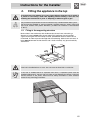
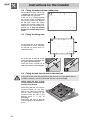
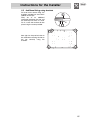
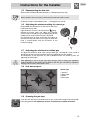
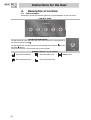
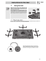
Contents
1. Precautions for safety and use________________________ 22
2. Fitting the appliance in the top ________________________ 23
2.1
2.2
2.3
2.4
2.5
Fixing to the supporting structure _______________________________________23
Fitting the adhesive foam rubber strip____________________________________24
Fitting the fixing clips ________________________________________________24
Fitting the hob into the hole in the work-top _______________________________24
Additional fixing using brackets ________________________________________25
3. Electrical connection _______________________________ 26
4. Gas connection ___________________________________ 27
4.1 Bottled gas connection _______________________________________________27
4.2 Room ventilation ____________________________________________________27
4.3 Combustion gas discharge ____________________________________________27
5. Adapting to different types of gas______________________ 28
5.1
5.2
5.3
5.4
5.5
5.6
5.7
5.8
5.9
Removing the hob skin _______________________________________________28
Adjusting for bottled gas ______________________________________________29
Adjusting for natural gas ______________________________________________29
Adjusting the primary air flow __________________________________________30
Reassembling the hob skin____________________________________________31
Adjusting the minimum setting for natural ga ______________________________31
Adjusting the minimum for bottled gas ___________________________________31
Hob burner layout ___________________________________________________31
Greasing the gas taps________________________________________________31
6. Description of controls ______________________________ 32
6.1 The front panel _____________________________________________________32
7. Using the hob _____________________________________ 33
7.1
7.2
7.3
7.4
7.5
Fitting the pan stands ________________________________________________33
Lighting burners with safety device______________________________________36
Positioning the griddle plate ___________________________________________36
Practical hints for using the burners _____________________________________36
Pan diameters______________________________________________________37
8. Cleaning and maintenance __________________________ 38
8.1 Cleaning the hob____________________________________________________38
8.2 Cleaning the components _____________________________________________38
THESE INSTRUCTIONS ONLY APPLY TO THE COUNTRIES OF DESTINATION WHOSE
IDENTIFICATION SYMBOLS ARE LISTED ON THE COVER OF THIS MANUAL.
THIS BUILT-IN HOB IS CLASSIFIED AS CLASS 3.
INSTRUCTIONS FOR THE INSTALLER: these are intended for the qualified
engineer who is to check the gas supply system and install, commission and test the
appliance.
INSTRUCTIONS FOR THE USER: these provide recommendations for use, a
description of the controls and the correct procedures for cleaning and maintaining the
appliance.
21
Precautions for Safety and Use
1.
Precautions for safety and use
THIS MANUAL IS AN INTEGRAL PART OF THE APPLIANCE. TAKE GOOD CARE OF IT AND KEEP IT
TO HAND THROUGHOUT THE HOB'S LIFE CYCLE. USERS ARE ADVISED TO READ THIS MANUAL
AND ALL THE INSTRUCTIONS IT CONTAINS BEFORE USING THE HOB. ALSO KEEP THE SET OF
NOZZLES PROVIDED IN A SAFE PLACE. INSTALLATION MUST BE CARRIED OUT BY QUALIFIED
STAFF IN COMPLIANCE WITH THE RELEVANT REGULATIONS. THIS APPLIANCE IS INTENDED FOR
HOUSEHOLD USE AND COMPLIES WITH THE EEC DIRECTIVES CURRENTLY IN FORCE. THE
APPLIANCE IS BUILT TO PROVIDE THE FOLLOWING FUNCTION: COOKING AND HEATING FOODS;
ALL OTHER USES ARE TO BE CONSIDERED IMPROPER.
THE MANUFACTURER DECLINES ALL LIABILITY FOR USES OTHER THAN THOSE STATED ABOVE.
NEVER LEAVE PACKAGING RESIDUES UNATTENDED IN THE HOME. SEPARATE WASTE
PACKAGING MATERIALS BY TYPE AND CONSIGN THEM TO THE NEAREST SEPARATE DISPOSAL
CENTRE.
THE APPLIANCE MUST BE CONNECTED TO EARTH IN COMPLIANCE WITH ELECTRICAL SYSTEM
SAFETY REGULATIONS.
THE PLUG TO BE CONNECTED TO THE POWER SUPPLY LEAD AND THE RELATIVE SOCKET MUST
BE OF THE SAME TYPE AND COMPLY WITH THE RELEVANT REGULATIONS.
THE POWER SUPPLY SOCKET MUST BE ACCESSIBLE EVEN AFTER THE APPLIANCE HAS BEEN
BUILT-IN.
NEVER DISCONNECT THE PLUG BY PULLING ON THE POWER SUPPLY LEAD.
IMMEDIATELY AFTER INSTALLATION, CARRY OUT A QUICK TEST ON THE HOB FOLLOWING THE
INSTRUCTIONS PROVIDED LATER IN THIS MANUAL. IF THE APPLIANCE FAILS TO OPERATE,
DISCONNECT IT FROM THE ELECTRICAL MAINS AND CONTACT YOUR NEAREST SERVICE
CENTRE.
NEVER ATTEMPT TO REPAIR THE APPLIANCE YOURSELF.
AFTER EACH USE OF THE HOB, ALWAYS CHECK THAT THE CONTROL KNOBS ARE TURNED TO
"ZERO" (OFF).
NEVER PLACE PANS WITH BOTTOMS WHICH ARE NOT PERFECTLY FLAT AND SMOOTH ON THE
HOB PAN STANDS.
NEVER USE PANS OR GRIDDLE PLATES WHICH PROJECT BEYOND THE OUTSIDE EDGE OF THE
HOB.
THE NAMEPLATE WITH THE TECHNICAL DATA, SERIAL NUMBER AND MARK IS IN A VISIBLE
POSITION UNDERNEATH THE CASING, ANNEXED TO THIS MANUAL AND APPLIED TO THE QUALITY
CERTIFICATE.
THIS NAMEPLATE MUST NEVER BE REMOVED.
THE APPLIANCE IS INTENDED FOR USE BY ADULTS. KEEP CHILDREN AT A SAFE DISTANCE AND
NEVER ALLOW THEM TO PLAY WITH IT.
THIS APPLIANCE IS TAGGED UNDER EUROPEAN DIRECTIVE 2002/96/EC ON WASTE ELECTRICAL
AND ELECTRONIC EQUIPMENT (WEEE).
THIS DIRECTIVE CONTAINS THE REGULATIONS GOVERNING THE COLLECTION AND RECYCLING
OF DECOMMISSIONED APPLIANCES THROUGHOUT THE EUROPEAN UNION.
The manufacturer declines all responsibility for injury or damage caused by failure to comply
with the above regulations or deriving from tampering with even just one part of the appliance
and the use of non-original spare parts.
22
Instructions for the Installer
2.
Fitting the appliance in the top
If the hob has to be adapted for a type of gas different from the one for which it
is preset in the factory, make this adjusting before building it into the unit,
following the instructions in point “5. Adapting to different types of gas”.
The procedures required below must be carried out by a skilled builder and/or joiner.
The hob can be installed on various materials, including masonry, metal, solid wood
and wood finished with plastic laminates, provided the material is heat-resistant
(T 90° C).
2.1 Fixing to the supporting structure
Make a hole in the cabinet top with the dimensions shown here, maintaining a
distance of at least 50 mm from the rear edge. This appliance may be installed
against walls higher than the worktop surface, provided the distance shown here is
maintained, in order to prevent damage due to overheating. Make sure that there is at
least 750 mm between the hob burners and a shelf or hood (if any) placed vertically
above them.
If the hob is installed above an oven, the oven must be fitted with a cooling fan.
If the hob is installed above a cupboard with doors, a separator panel must be
installed underneath it. Leave a gap of at least 10 mm between the bottom of the hob
and the surface of the panel, which must be easily removable to allow sufficient
access for any servicing procedures.
23
Instructions for the Installer
2.2 Fitting the adhesive foam rubber strip
Fit the adhesive foam rubber strip
(supplied with the hob) around the
outside edge of its surround.
It will act as a cushion between
the surface of the surround and
that of the cabinet. The diagram
on the right shows the correct
position for the foam rubber strip.
Take great care when fitting it to
ensure that it does not project
beyond the outside edge of the
frame.
2.3 Fitting the fixing clips
Fit the fixing clips in all the points
marked with an arrow. The clips
fix the hob an ensure that it is
centred correctly.
To fit the clips to the hob, simply
press them gently horizontally into
the groove provided (fig. A).
Then turn them upwards to fix
them permanently in place (fig. B).
2.4 Fitting the hob into the hole in the work-top
Take special care when fitting the hob into the work-top. If the procedures are not
carried out correctly, exactly as described, the hob may be damaged.
Before fitting the hob, remove
the pan stands (if fitted) and the
burners from the hob.
When fitting the hob, first rest the
surround entirely on the back
edge of the hole in the work-top.
Do not apply leverage to the
surround; since this part is very
delicate there is a risk of
damaging it.
Then lower the front of the hob
until the appliance is completely in
place.
24
Instructions for the Installer
2.5 Additional fixing using brackets
For even more secure fixing, the
brackets provided can be used in
addition to the clips.
They act as an additional
connection between the hob and
the work-top into which it is built.
To fix, screw the brackets A into
place using the screw provided.
See right for the precise holes to
be used when securing the hob to
the top correctly using the
brackets.
25
Instructions for the Installer
3.
Electrical connection
Check that the power supply line voltage and size are as specified on the nameplate
underneath the appliance's casing. This nameplate must never be removed.
The plug on the end of the power supply lead and the wall socket must be of the same
type and comply with the relevant regulations. Check that the power supply line is
properly earthed.
Pass the power supply cable through the rear of the cabinet, taking care that it does not
touch the bottom case of the hob, or the oven (if any) built in underneath it.
The appliance's power supply line must be fitted with an omnipolar breaking device with
contact gap of at least 3 mm, located in an easily accessible position close to the
appliance itself.
The use of reductions, adapters or junctions is not recommended.
If the power supply cable has to be replaced, the gauge of the wires in the new cable must
be at least 0.75 mm2 (3 x 0.75 cable), bearing in mind that the earth wire (yellow-green)
must be at least 20 mm longer at the end for connection to the appliance. Use only a type
H05V2V2-F or similar cable resistant to a temperature of up to 90°C. The cable must be
replaced by a qualified electrician, who must make the mains connection as shown below.
L = brown
N = blue
= yellow-green
The power supply lead must be replaced by an authorised service centre to prevent all
risks.
The manufacturer declines all responsibility for injury or damage caused by failure to
comply with the above regulations or deriving from tampering with even just one part
of the appliance.
26
Instructions for the Installer
4.
Gas connection
If the appliance is installed above an oven, the gas hose must be passed around the back
of the oven to prevent overheating.
The connection to the gas mains may be made using a copper pipe or a continuous-wall
steel hose in accordance with the relevant regulations. To simplify connection, the
horizontal position of the fitting A on the back of the appliance is adjustable. Undo the
hexagonal nut B, turn the fitting A into the required position and re-tighten the hexagonal
nut B (it has a rubber gasket to ensure it provides an effective seal). When installation is
complete, check for any leaks with a soapy solution, never with a naked light. The
appliance is tested with G20 (2H) natural gas at the pressure of 20 mbar. For use with
other types of gas, see point "5. ADAPTING TO DIFFERENT TYPES OF GAS". The gas
intake connection has an external ½” gas thread (ISO 228-1).
Connection with copper pipe: The connection to the gas
supply mains must be made so that no stresses or strains
of any kind are applied to the appliance. The connection
can be made using the adapter unit D with two conical
elements, always fitting the gasket C supplied.
Connection with steel hose: use only continuous-wall
stainless steel hoses compliant with the relevant
regulations, and always fit the gasket C supplied between
the fitting A and the hose E.
When connecting with a hose, ensure that the total length of the pipeline is not more
than 2 metres; also ensure that the hoses do not touch moving parts and are not
crushed.
4.1 Bottled gas connection
Use a pressure regulator and make the connection to the gas cylinder in accordance
with the relevant regulations. Make sure that the gas supply pressure is as stated in
the table in point "5.2 Adjusting for bottled gas".
4.2 Room ventilation
The appliance may only be installed in a permanently ventilated room as specified by
the relevant regulations. The air flow into the room where the appliance is installed
must be sufficient for proper gas combustion and room ventilation. The air intakes,
protected by gratings, must be of suitable size (see relevant regulations) and located
so that they cannot be even partially obstructed.
The kitchen must be kept properly ventilated to disperse the heat and humidity
produced by cooking processes: in particular, a window should be opened or the
speed of any fans increased after prolonged use.
4.3 Combustion gas discharge
Combustion gases must be discharged by means of hoods connected to a flue with
reliable natural draught, or a fan extraction system. An effective extraction system
requires careful design by an authorised specialist, and must comply with the
regulation distances and positions. After installation, the engineer must issue a
certificate of compliance.
27
Instructions for the Installer
5.
Adapting to different types of gas
The operations described below must be carried out with the appliance not
built-in and not connected to the gas or electricity supply.
The appliance is tested with G20 (2H) natural gas at the pressure of 20 mbar.
If it is to be used with other types of gas, the burner nozzles have to be changed
and the primary air flow adjusted.
To replace the nozzles and adjust the burners, the hob skin has to be removed.
Proceed as described below.
5.1 Removing the hob skin
Remove all the burner components in the numerical order shown below:
•
Pull off all the knobs.
•
Lift
all
the
burner
components off the hob.
1
•
Remove the cover plate
of each burner by
undoing the screws.
2
•
Remove the hob
fixing screws, taking
only to remove
screws shown on
right.
skin
care
the
the
3
•
After removing all the
components
described
above, lift off the hob
skin.
4
28
Instructions for the Installer
5.2 Adjusting for bottled gas
Undo the screw C and push the air regulator
D fully down.
Remove the nozzle E with a 7 mm spanner
and fit the suitable one, following the
instructions in the tables referring to the type
of gas to be used. The nozzle must not be
tightened with a torque of more than 3 Nm.
Regulate the air flow by sliding the regulator D
along until the distance “X” stated in point "5.5
Adjusting the primary air flow” is obtained.
Fix the regulator D by tightening the screw C.
Burner
Auxiliary
Semi rapid
Rapid
Ultra Rapid
Rated
heat
capacity
(kW)
Bottled gas – G30/G31 30/37 mbar
Nozzle
diameter
1/100 mm
By-pass
mm
1/100
48
62
80
108
30
32
50
63
1.05
1.7
3.0
5.0
Reduced
heat
capacity
(W)
400
450
1050
1600
Flow
rate g/h
G30
Flow
rate g/h
G31
76
124
218
363
75
121
214
357
5.3 Adjusting for natural gas
The appliance is tested with G20 (2H) natural gas at the pressure of 20 mbar. To return the
appliance to the condition required to use this type of gas, proceed as described in point “5.2
Adjusting for bottled gas” but select the nozzles and adjust the primary air flow for natural gas,
as indicated in the table below and in point “5.5 Adjusting the primary air flow”.
Burner
Auxiliary
Semi rapid
Rapid
Ultra Rapid
Rated heat
Capacity (kW)
1.05
1.7
3.0
5.0
Natural gas - G20 20 mbar
Nozzle diameter
1/100 mm
73
92
123
165
Reduced heat capacity
(W)
400
450
1050
1400
29
Instructions for the Installer
5.4 Adjusting the primary air flow
Refers to the gap “X” in mm.
G20
20 mbar
0.5
G30/G31
30/37 mbar
9.5
Semi rapid
1
1
Rapid
2
3
Ultra Rapid
4
open
BURNER
Auxiliary
To identify the burners on your hob, refer to the drawings in point “5.8 Hob burner
layout”.
30
Instructions for the Installer
5.5 Reassembling the hob skin
Reverse the procedure described in point “5.1 Removing the hob skin”.
When replacing the cover plates, check that the seals are fitted correctly.
Fit the pan stands as described in point
7.1Fitting the pan stands.
5.6 Adjusting the minimum setting for natural ga
Reassemble the components on the burner and fit the
knobs onto the tap rods.
setting.
Light the burner and turn it to the minimum
Remove the knob again and adjust the regulator
screw inside or beside the tap rod (depending on the
model) until an even minimum flame is obtained.
Put the knob back in place and check the stability of
the burner flame (the flame must not go out when the
knob is turned quickly from the maximum to the
minimum setting).
5.7 Adjusting the minimum for bottled gas
To adjust the minimum level when using bottled gas, the adjuster screw inside or
beside the tap rod must be turned fully clockwise (depending on the models).
The diameters of the bypasses for each individual burner are stated in point “5.2
Adjusting for bottled gas".
After adjusting for use of a gas other than the gas used for testing the appliance,
replace the label on the casing with the label for the new gas. The label is supplied in
the bag with the LPG nozzles (G30 - G31).
5.8 Hob burner layout
Burner type
1 Auxiliary
2 Semi rapid
3 Rapid
4 Ultra rapid
5.9 Greasing the gas taps
Over time, the gas taps may become stiff or jam. Clean their insides and change their
lubricating grease. This operation must be carried out by a skilled technician.
31
Instructions for the User
6.
Description of controls
6.1 The front panel
All the hob's control and monitoring devices are placed together on the front panel.
CONTROL AREA
5 Burner Hob
KNOB OPERATING MODE
To light the flame, press the knob and at the same time turn it anti-clockwise to
the minimum flame symbol .
To adjust the flame, turn the knob to the zone between the maximum
minimum settings.
To turn off the burner, turn the knob back to the O position.
and the
BURNER LAYOUT - Key to symbols
32
Front left-hand burner
Rear left-hand burner
Rear right-hand burner
Front right-hand burner
Middle burner
Instructions for the User
7.
Using the hob
Check that the fixing cover plates E, the
burners, the flame diffuser rings and the pan
stands are fitted correctly.
The projections A on the flame diffuser rings
must be fitted into the recesses B in the burner.
The holes C in the burner must mate with the
ignition plugs and thermocouples D on the hob.
7.1 Fitting the pan stands
The pan stands are supplied dismantled from the hob. To place each pan stand on its
burner correctly, follow the instructions provided below:
The ends of the feet of each pan stand carry
silicone rubber pads with holes which must be
fitted onto the fixing pins provided on the hob.
33
Instructions for the User
To fit the pan stand, first align it with the fixing
pin (1) and then lower it into place on the hob,
taking care that it fits over the flame diffuser
ring correctly (2).
Each pan stand will only fit onto its own burner.
To ensure correct positioning, each pan stand
has a different recess (as shown here) which
will fit over the projection on the corresponding
flame diffuser ring.
Take great care to fit the correct pan stand on
each burner. After the pan stand is fitted its feet
must rest on the hob and not be suspended
above it.
Make sure that the pan stands are simply fitted over their burners, and are not
left in a raised or tilted position; if this occurs, repeat the fitting procedure.
34
WRONG
RIGHT
WRONG
RIGHT
Instructions for the User
After performing the operations described above (for each pan stand), the hob will be
as shown below, with the feet of the pan stands forming a pattern of horizontal and
vertical lines.
If a pan wobbles noticeably, check that the pan stands have not been fitted
incorrectly.
35
Instructions for the User
7.2 Lighting burners with safety device
The burner it controls is shown next to each knob (the example here shows the front
left-hand burner).
The appliance is equipped with electronic ignition. Simply press the knob and turn it
anti-clockwise to the minimum flame symbol , until the burner lights. Keep the knob
pressed down for about 2 seconds to keep the flame alight and prime the safety
device. The burner may go out when the knob is released. In this case, repeat the
operation, keeping the knob pressed down for longer.
When the burner has lit, its control knob will light up to confirm that it is in operation.
The knob will go out a few seconds after it is turned to the O position, or if the burner
goes out accidentally. The knob light comes on and goes out gradually.
If the burners should go out accidentally the safety device will be tripped about 20
seconds later, cutting off the gas supply even if the gas tap is open.
7.3 Positioning the griddle plate
A special griddle plate for use with the hob is available from authorised dealers. This
plate must be PLACED ON THE PAN STANDS, PROPERLY CENTRED. It must never
be fitted instead of a pan stand.
Ensure that the griddle plate is properly centred on the pan stands; if it is not correctly
positioned, the knobs may overheat while it is in use.
7.4 Practical hints for using the burners
For better burner efficiency and to minimise gas consumption, use flat,
even -bottomed pans with lids of suitable size for the burner (see point "7.3
Pan Diameters").
When cooking, to prevent burns or damage to the hob all pans or griddle
plates must be placed inside the perimeter of the hob and must be at least
5-7 cm from the knobs.
36
Instructions for the User
7.5 Pan diameters
BURNERS
1 Auxiliary
2 Semi rapid
3 Rapid
4 Ultra Rapid
min. and max. Ø
(in cm)
7-18
10-24
18-24
20-28
37
Instructions for the User
8.
Cleaning and maintenance
Before carrying out any operations, disconnect the appliance from the
electricity supply.
Never use a jet of steam for cleaning the appliance.
8.1 Cleaning the hob
To keep the hob in good condition, it must be cleaned regularly, after each use, first
allowing it to cool.
8.1.1
Routine daily glass hob cleaning
When cleaning and caring for glass surfaces always use only specific products which
do not contain abrasives or chlorine-based acids.
Instructions for use: pour the product onto a damp cloth and wipe over the surface,
then rinse thoroughly and dry with a soft cloth or chamois leather.
8.1.2
Food stains or spills
Never use metal scouring pads or sharp scrapers which will damage the
surface.
Use ordinary non-abrasive products for glass, with the aid of non-scratching
sponges and wooden or plastic utensils if necessary.
Rinse thoroughly and dry with a soft cloth or chamois leather.
8.2 Cleaning the components
Never clean the knobs with aggressive products containing alcohol or steel or glass
cleaners, since they might cause permanent damage.
NEVER REMOVE THE FIXING COVER PLATES TO CLEAN THE HOB.
The components described below must never be washed in a dishwasher.
8.2.1
The knobs
The knobs must be cleaned with a soft cloth dipped in warm water and dried
thoroughly. They can easily be lifted off.
8.2.2
The pan stands
Remove the pan stands and wash them in warm water with a non-abrasive detergent,
taking care to remove all deposits. Replace them on the hob following the instructions
provided in point “ 7.1Fitting the pan stands”.
8.2.3
The flame diffuser rings
The burner caps and flame diffuser rings can be removed for easier cleaning; wash
them in hot water and non-abrasive detergent, taking care to remove all deposits, and
wait for them to dry completely.
The burner pins A must be fitted into the recesses B in the flame diffuser ring. The
holes C in the flame diffuser ring must mate with the ignition plugs and thermocouples
D on the hob.
8.2.4
The plugs and thermocouples
For best performance, the ignition plugs and thermocouples must always be kept
thoroughly clean. Check them frequently and if necessary clean them with a wet cloth.
Remove any dry residues with a wooden toothpick or a needle.
38