1
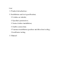
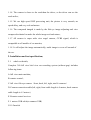
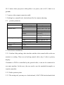
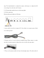
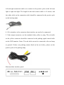
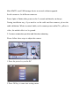
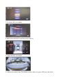
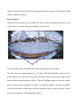
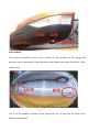
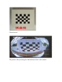
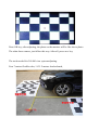
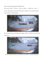
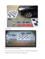
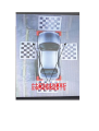
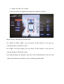
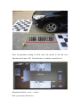
360 degree full view bird view car recording system
(without gap for four pictures)
User manual
List
1. Product introduction;
2. Installation and test specification;
2.1 whole set details;
2.2 product parameters;
2.3 notes before installation;
2.4 cable connection;
2.5 camera installation position and direction testing;
2.6 software testing
3. Manual
1. Product introduction
This product is made up of one central processing unit and four super wide view
angle camera; Through the four wide view angle camera(left, right, front and back
camera), the central processing unit catch the image all around the car, after
processing, there will be a 360 degree full vertical view photo on the monitor. With
this newest car recording system, driver could park the car or pass the crowded road
easily without rubbing, colliding or dropping accident. (Following are real photo)
1.1
Advantage
1.1.1 It is not only the full view parking assistant system, but also the four
channels car driving recording system, which advance the driving and parking to
be safest.
1.1.2 It combined front, back, left and right four direction image together, and
make to be one vertical view. So no matter to driving forwarder, backing, turn
direction, the car head, car back, left or right are exact on the monitor.
1.1.3 There are parking, left turn, right turn three ways force signal cable;
1.1.4 The camera is closer to the road than the driver, so the driver can see the
road earlier;
1.1.5 We use high speed DSP processing unit, the picture is very smooth, no
speed delay, and very real and nature.
1.1.6 The composed imaged is made by the fish eye image adjusting and view
composed technical to make the whole image real and nature;
1.1.7 All camera is super wide view angel camera, CVBS signal, which is
compatible to all models of car monitor;
1.1.8 It will adjust the image automatically, multi image to cover all around of
the car.
2. Installation and test specification;
2.1
whole set details;
Complete 360 full view bird view car recording system (without gap) includes
following items:
A. full view main machine;
B. remote control;
C. full view fish eye camera(front, back, left, right, total 4 cameras)
D. Camera connection cable(left, right, front cable length is 4 meters, back camera
cable length is 6.5 meters)
E. Remote control receiver
F. 1 meters USB cable(to connect USB)
G. 19.2mm bit
H. 1.2 meters three pin power cable(yellow is to power, red to ACC, black is to
ground)
I. 2 meters video output connection cable
J. Packing box, manual book, checkerboard for the camera adjusting.
2.2
product parameter
items
system
Main
machine video
Device parameter
Operation language
Operation interface
Video input
Video output
Video display
Video standard
Image compressor
Image processing and storage
Software upgrade
Work voltage
Work current
Work temperature
left
right
backing
Upgrade by USB
9-36V
440mA
-30°-80°C
details
Chinese/English
Image menu (OSD menu)
channels multi video input
Single multi video output
Full view 360 degree vertical view
PAL/NTSC
H.264 main profile. Compressor
source is 25D/Sec.
Display left side view
Display right side view
Standard full view
2.3 notes before installation;
2.3.1 Confirm if the parking video interface and the video control cable on the car
monitor is working. There are no backing control cable, only if video is priority
display.
If monitor or DVD is controlled by the general cable, it can not be connected to
our main machine. In this case, the user need to use the matched decompiler or
transfer controller.
2.3.2 Find a spacious place.
2.3.3 The testing tool you may use: checkerboard, 1.6M*1.2M checkerboard cloth
strip. The checkerboard is to adjust the camera, cloth strip is to adjust the full
view setting. Four role rules with 7 meters.
2.3.4 Do not adjust under the sun or with strong light.
2.4 Cable connection
Main machine panel photo as following:
1. power cable, the red is to connect ACC, the yellow is to connect power, black
is to connect ground.
2. Remote receiver, to use the four pin earphone plug. When connect, to make
sure that it connects properly. And put the receiver to the wide open place.
3. There are four meters cables for front, left and right camera. The white cable of
left and right connection cable is to connect to the positive pole on the left turn
light or right turn light. The length for the back camera cable is 6.5 meters, and
the white cable on the connection cable should be connected to the positive pole
on the backing light.
4. AV in interface is the extension video interface, no need to be connected;
5. Video output connector, use the standard video yellow av plug, The red cable
on the yellow connector should be connected to the parking signal control cable
on the DVD monitor. Notes: The red cable can not be connected to the car lamp
or ground. If there was parking camera fixed on the car before, please cut the
positive pole of the parking lamp.
Main machine interface panel:
Mini SD(TF) card, USB storage device to record, software upgrade
Serial connector: for different connector
Power light: it flashes after power on for 3 second, and then be on always.
During installation way, if you need to cut the cable and then connect, pls not the
cable definition: White is control cable, red is camera power cable(5V), yellow is
video, the naked cable is to be ground.
2.5 camera connection position and direction adjusting
Please follow these steps to adjust the camera
1.Press the power key on the RC
2.Press OK key to come into setting menu
3.To choose full view adjust
4.Input password654321 and then press OK key
5.Come into full view adjust
6. Adjust the camera lens: The default picture after you press OK key is the front
image. You press the up, down, left and right arrow to change to left camera, right
camera and back camera.
Front camera
When you fix the camera, try to make the lens to face to the ground, and try to not
to face the car bumper. Keep the camera to be on lever.
Left and right camera installation position and hole making solution
The hole saws for camera diameter is 19.2mm. The hole should be made as close
as the edge of the rearview mirror (the outboard), much closer to the edge, much
better for the connection photo effects. The two Oblique rings is to fix the camera
to be vertical to the car body. The gule is to make the open to be more beautiful.
Note that the holes on the right and left should be almost same, and not to hide
the lens movement as following photo show:
Left camera
Left camera should be fixed to be vertical to the ground, so the image and
monitor can be horizontal. Both the front wheel and read wheel should be in the
camera lens.
Car is in the middle of frame of the green line, try to keep the car body to be
balance.(horizontal).
Right camera
Right camera should be fixed to be vertical to the ground, so the image and
monitor can be horizontal. Both the front wheel and read wheel should be in the
camera lens.
Car is in the middle of frame of the green line, try to keep the car body to be
balance.(horizontal).
Rear view camera
Normally, the rear view camera should be special based on different car model.
Just to keep the image to be horizontal.
2.6 Software adjust
1. Adjust the lens
Press Power on the RC----OK key----full view adjust---- adjust lens. Take out the
checkerboard and put it to be close to the camera. It needs two people to
cooperate, one is to bring the checkerboard to the camera, after fix the location,
the other one press OK key on the RC.
Checkerboard
The picture after you bring the checkerboard close to the camera
Press OK key, after adjusting, the photo on the monitor will be like above photo.
The other three camera, just follow this way. After all, press save key.
The tools needed for 360 full view system adjusting.
Four 7 meters flexible rules, 1.6*1.2 meters checkerboard,
How to put the checkerboard and flexible rules
Press power on RC----OK key-----full view adjust----- adjust lens-----press ↑
to show front camera. Open the flexible rules, and put it to the visible position
of the camera as following photo:
Put the flexible rules to the edge of the bumper, where is visible on the monitor by
the camera
Put the checkerboard near to the flexible rule with the 1.6 meter end, keep it
in the middle of the car as following photo:
Rear checkerboard and flexible rule
Same as above
Left flexible rule and checkerboard
Put the flexible rule to be close to the wheel, and pull the rules from the
headstock to the tailstock
Checkerboard
Right flexible rule and checkerboard
It is same with the left side, but note that the checkerboard starting position
should be same as left checkerboard starting position.
2. Adjust 360 full view system
Come into full view adjustment, input three number as photo:
Model choose: Medium (system default)
Car width: car body width ( you can check on the website or on your car
driving license), calculate by mm.
Car length: car body length (you can check on the website or on your car
driving license), calculate by mm.
Left right shifting: the distance from the front checkerboard to the left and
right checkerboard, calculate by mm as following photo show:
After all parameter setting is fixed, move the mouse to the full view
adjustment and press OK. Note that there is nobody around the car.
Adjustment finish----save----return
Now you can use this device.
3. Product operation details
After installation, follow these steps:
1. There is full view on the monitor when backing+ rearview photo;
2. During driving, press emergency light twice or press Power on RC to
start full view. If you need to close, operate same way.
3. If you need to record during driver, connect USB or TF card to the
main machine. When you want to play back, come into menu and
choose playback.