1
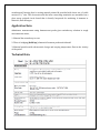
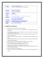
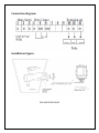
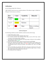
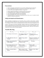
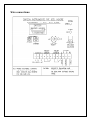
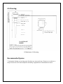
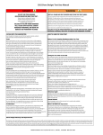
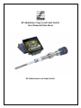
RF Admittance Type Level Limit Switch
User Manual & Data Sheet
RF Admittance Level Limit Switch
Table of contents
1. Introduction……………………………………………………………………………………………………01
2. Operating Principle………………………………………………………………………………………….02
3. Features………………………………………………………………………………………………………….03
4. Application Note……………………………………………………………………………………………...04
5. Technical Data………………………………………………………………………………………………...05
6. Installation Guidelines……………………………………………………………………………………..06
7. Calibration………………………………………………………………………………………………………07
8. Precautions……………………………………………………………………………………………………..08
9. Maintenance……………………………………………………………………………………………………09
10. Trouble Shooting…………………………………………………………………………………………….10
11. Recommended Spares……………………………………………………………………………………..11
12. Warranty………………………………………………………………………………………………………..12
13. Customer Service…………………………………………………………………………………………….13
Introduction:
Sapcon admittance level limit switch utilizing specially designed Immunocoat probe
offers a reliable solution to level detection problems so far difficult to solve with
capacitance type system utilizing conventional probes. The main advantage offered by
admittance range of level switches is their ability to ignore build up and coating of material
on the probe. Purpose of adding a shield in between sensing element and ground is to avoid
RF currents from reaching the container wall via the coating. Although there would be
RFcurrent flowing between the shield and the container wall via the build up, it would not
be considered by the measuring circuit and will not affect on the level measurement. This
unique design enables the electronic circuitry to distinguish between significant process
coating and the actual process material thereby gives reliable accurate switching.
.
Operating Principle:
The sensing element and the container wall (or ground electrode) form a means to
measure the admittance of the system with & without the intervening material. When all
the parameters that affect the admittance value are kept constant then its value changes
only due to the difference in material level. The sensed signal is further amplified and used
to actuate the relay. The relay contacts are used for alarm or control purpose.
System Description & Features:
A complete measuring system comprises:
I. Evaluation unit
II. Immuno coat probe
III. Interconnecting cable
Immunocoat probe is of a special construction with three concentrically positioned
electrodes that are electrically insulated from each other. The innermost electrodes serve
as the sense electrode whereas the one next to it is the shield, and the outermost is ground.
The sense electrode is connected to a radio frequency source and the shield is also
connected to the same source but through an isolating amplifier. They therefore have
identical waveforms and the shield follows the sense, maintaining equivalent potential,
frequency and phase relationship. Due to this there is no flow of RF current between the
shield and the sense electrode. The flow of RF currents via the shield to sidewalls does not
affect the measurement due to isolation amplifier
.
The probe head is of cast aluminum weatherproof construction provided with suitable
cable glands, and fitted on to the probe mounting arrangement. A discharge device is
provided with the system where there is a possibility of generation of static charge in the
service material. The immuno coat probe is connected to the evaluation unit with a special
screened cable of pre- trimmed length. The Evaluation unit is housed in a cast aluminum
weatherproof housing that is stoving enamel painted & provided with three nos. of cable
entries of ½" size. The electronics and the inter-connecting terminals are assembled on a
glass epoxy printed circuit board that is heavily lacquered for rendering it immune to
moisture, dust & fungus.
Application Note:
Admittance measurement using Immunocoat probe gives satisfactory solution in tough
environments where,
1. Material has a tendency to coat.
2. There is bridging (build up) of material between probe and sidewall.
3. Material particles with electrostatic charge and varying temperature float in the vicinity
of the probe.
Technical Data:
Installation Guidelines:
Instrument can be installed in almost any position.
Install probe in such a way that sense, shield & non active length must come in
active zone.
The threaded mounting connection should be as short as possible to avoid deposit
of material in the nozzle cavity.
When mounting is from side, the cable entry should be pointing downwards, so that
no moisture can enter.
Make sure that the probe insulation is not damaged when inserting through the
nozzle.
Probe should be installed away from the inlet. If it is not possible, fix baffle plate 300
mm above from the probe.
Always refer the attached diagram before making the interconnection.
One such diagram is also pasted inside the evaluation cover.
Connect the mains supply as mentioned inside the cover.
Verify the line voltage before switching ON the instrument.
Interconnection b/w probe and evaluation unit is made by special PTFE coaxial
cable of pretrimmed length.
Ensure control unit is earthed properly.
Use three core cables of 1.5 sq mm diameters, in case of AC power supply & relay
contacts.
Connection diagram:
Installation Figure:
SIDE MOUNTED PROBE
Calibration:
(For DOT Display Model SLA…M Series)
A DOT DISPLAY model serves as a sensitivity indicator. The indicator range is divided in to
TEN parts. The divisions are as follows:
Sensitivity Regions
The Following standard procedure should be carried out when tank is empty.
Switch ON the mains voltage.
Select the desired fail safe by using FSS toggle switch.
For versions provided with adjustable time delay, turn the POT fully counter
clockwise to the minimum delay condition.
Now rotate the sensitivity adjustment POT fully counter clockwise. In this condition
the DOT display will be GREEN.
Fill the level up to the probe, so that it covers the probe tip sufficiently.
Rotate the sensitivity POT gradually clockwise observing the DOT display move
through the green and yellow region to the RED region. Continue the turning of
potentiometer until the relay just operates. This should occur close to the RED
region.
Without disturbing the sensitivity POT reduce the level of material. As the probe
gets uncovered the DOT display will move from RED through Yellow to Green.
Record this display indication for future reference.
The calibration is now completed.
(For BAR Display SLA…B series)
The following standard procedure should be carried out when tank is empty.
Switch ON the mains power supply.
Select the desired fail-safe by using FSS toggle switch.
For version provided with adjustable time delay, turn the POT fully counter
clockwise to the minimum delay condition.
Ensure all the four DIP switches just below SENS trimmer are in OFF position.
Note the display in SENS/DEV indicator.
If all the RED LEDs are glowing along with the alarm RED LED, the turn the SENS
trimmer slowly towards anticlockwise.
If alarm condition does not change, then PUT DIP switches 1 to ON condition. If the
RED LED alarm still glows than put DIP switch 1 to OFF condition & turn the DIP
switch2,3 or 4 to ON condition till green LED glows & note if SENS/DIV indicator
shows any LED glowing.
Rotate the SENS trimmer slowly towards clockwise direction till display is ON.
SESN/DIV indicator shows 4 LED’s glowing.
Fill the level up to probe, so that it covers the probe tip sufficiently.
If the RED alarm LED glows along with the relay changeover, than the calibration is
complete.
If the green LED still glows that further rotate the SENS trimmer clockwise till the
RED alarm LED glows.
NOTE: For probe uncovered and display set to 6th LED, the Green indicator LED glows
when FSS is set to High mode whereas Red indicator LED glows when FSS is set to Low
mode.
Fail Safe Mode:
This is field selectable option depending upon the process requirement. Maximum fail safe
or minimum fail-safe can be obtained by selecting the FSS toggle switch mounted in the
centre of the PCB. De-energized condition of the relay is used to initiate an alarm. Even if
the mains supply fails or instrument doesn’t work, relay will initiate an alarm.
Maximum Fail Safe - When the level rises and the material covers the probe the relay is
de-energized, an alarm is initiated and Red LED glows. For achieving this mode of
operation shift the toggle switch to fail safe high.
Minimum Fail safe - When the level falls and the probe is un-covered, the relay is deenergized, an alarm is initiated and Red LED glows. For achieving this mode of operation
shift the toggle switch to failsafe low.
Precautions:
Refer the diagram pasted inside the cover before making the interconnection.
Do not immediately energize the instrument until wires are fully secured.
In case of DC power supply instrument –ve is ground.
Always tighten the housing cover and the cable entry securely.
Use appropriate size of spanner for rotating mounting bush.
True earths must be connected to the instrument.
Use recommended cable only for interconnection.
Weatherproofness of enclosure is guaranteed only, if the cover is in place & cable
glands are adequately tightened.
Safety Information & Maintenance:
Before installing the admittance level controller, please read these instruction’s carefully
and familiarize yourself fully with the requirement and functions of the instrument. Please
do not dispose off the carton or packing material until the unit has been inspected in all
respects. If the unit is received in damaged condition, kindly note the dispatch details and
inform us immediately Interconnection must be done as per the national standards. If you
find any difficulty or have any doubts about installing this product, please do not hesitate to
contact our service center for instant support.
Trouble Shooting:
Wire connections:
DOT DISPLAY CONNECTIONS
GA Drawing:
RF Admittance GA Drawing
Recommended Spares:
* Instrument having no moving part therefore no wear and tear. However we advice to
keep at least one set of card and probe assembly, if population of instrument are more.
Warranty:
Instrument is manufactured as per the purchase order specification. Standard guarantee
for twelve months from the date of commissioning or eighteen months from the date of
supply. Which ever is earlier. Guarantee is against manufacturing defects. We undertake to
correct such defects which are due to workmanship, at our expenses, Instrument should be
forwarded to us on freight paid basis with seals unbroken. The guarantee is valid for our
customer and does not extent to third parties or caused by mishandling, accident or
abnormal conditions.
Customer Service:
If you require any assistance or clarification please free to contact with following details at
the address given below.
A. Instrument Model & serial no.
B. Purchase order no. & date
C. Problem observed
Sapcon Instruments (P) Ltd
131, Palshikar colony
Indore 452004
India
Ph no.0731-2475751-52-53, 4082751
Fax 0731- 2475475
Email [email protected], [email protected]
Website www.sapconinstruments.com