1
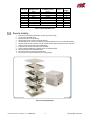
IDAN® Connector Location
Figure 7: IDAN® Connector Location
IDAN-LAN10257HR
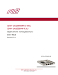
This utilityModule is also available in an IDAN® configuration. The IDAN® module is shown below.
Figure 8: IDAN-LAN10257HR Rear View
Figure 9: IDAN-LAN10257HR Front View
IDAN® Twisted Pair Ethernet P1, P2, P3, P4, and P5
As an IDAN®, the Ethernet signals are available on five “D” connectors, two on the front and three on the back. A DB-9 to RJ-45 adapter is
also included for each port. The pin out is listed in the table below.
RTD Embedded Technologies, Inc. | www.rtd.com
16
LAN10257HRHR User’s Manual