1
PC-Tool V3.5 main document, user manual
Main document
User Manual
English
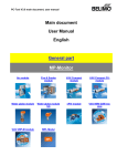
General part
MP-Monitor
Air module
Fire & Smoke
module
VAV-Compact
module
EPIV Module
VAV NMV-D2M
module
VAV VRP-M module
Water stroke module
PC-Tool V3.5 General part, user manual
PC-Tool V3.5
User Manual
English
General Part
1 /51
PC-Tool V3.5 General part, user manual
Table of Contents
1
Basics ................................................................................................................................ 4
1.1 Introduction ............................................................................................................... 4
1.2 Information on using the manual............................................................................... 4
1.3 General structure of the user interface...................................................................... 5
1.4 Modules and actuator types ...................................................................................... 6
2
Getting started with PC-Tool ............................................................................................. 7
2.1 Connecting the computer with the actuators............................................................. 7
2.2 Starting the program ................................................................................................. 7
2.3 Adapting PC-Tool options ......................................................................................... 7
2.4 Creating a new project .............................................................................................. 8
2.5 Setting up the program.............................................................................................. 8
2.6 Displaying actuator parameters ................................................................................ 9
2.7 Further actions .......................................................................................................... 9
3
Basic functions ................................................................................................................ 10
3.1 Program start .......................................................................................................... 10
3.2 Projects ................................................................................................................... 11
3.2.1 Project data ................................................................................................ 11
3.2.2 Creating a new project ............................................................................... 11
3.2.3 Opening a project....................................................................................... 11
3.2.4 Changing project data ................................................................................ 11
3.2.5 Exporting a project ..................................................................................... 12
3.2.6 Copying a project ....................................................................................... 12
3.2.7 Deleting a project ....................................................................................... 12
3.3 MP-Channel ............................................................................................................ 12
3.3.1 Serial interface ........................................................................................... 12
3.3.2 Bus scan .................................................................................................... 13
3.4 Setting the bus address .......................................................................................... 14
3.4.1 Series addressing of actuators................................................................... 14
3.4.2 Addressing with known serial numbers...................................................... 16
3.4.3 Resetting actuator addresses .................................................................... 17
3.4.4 Addressing a single actuator...................................................................... 18
3.5 Selecting a module.................................................................................................. 19
3.6 Actuator parameters................................................................................................ 20
3.6.1 Displaying actuator parameters ................................................................. 20
3.6.2 Printing out actuator parameters................................................................ 20
3.6.3 Deleting maintenance/error messages ...................................................... 20
3.7 Configuring an actuator........................................................................................... 22
3.7.1 Saving a parameter file .............................................................................. 23
3.7.2 Loading a parameter file ............................................................................ 23
3.7.3 Copying parameters................................................................................... 23
3.7.4 Load factory settings .................................................................................. 23
2 /51
PC-Tool V3.5 General part, user manual
3.8 Parameterizing limited lots ...................................................................................... 25
3.9 Printing labels.......................................................................................................... 28
3.9.1 Setting up a configuration file..................................................................... 28
3.9.2 Printing labels............................................................................................. 28
3.9.3 Printing labels offline .................................................................................. 29
3.10 Transformation tables ............................................................................................. 29
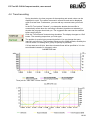
3.11 Displaying recorded trend data ............................................................................... 32
3.12 PC-Tool options ...................................................................................................... 33
3.13 Log file..................................................................................................................... 34
4
Attachment ...................................................................................................................... 36
4.1 Storage locations of files ......................................................................................... 36
4.1.1 Project data ................................................................................................ 36
4.1.2 Configuration files ...................................................................................... 36
4.2 Configuration files for printing labels ....................................................................... 37
4.2.1 Storage location ......................................................................................... 37
4.2.2 Format........................................................................................................ 37
4.2.3 Boxes ......................................................................................................... 38
4.2.4 Example of a label...................................................................................... 40
4.3 Troubleshooting and error messages ..................................................................... 41
4.3.1 General ...................................................................................................... 41
4.3.2 Error messages.......................................................................................... 41
4.3.3 ISO 8859-1/ANSI character set.................................................................. 46
4.4 Typical wiring diagrams........................................................................................... 47
4.4.1 Overview table ........................................................................................... 47
4.4.2 Typical wiring diagrams.............................................................................. 48
3 /51
PC-Tool V3.5 General part, user manual
1 Basics
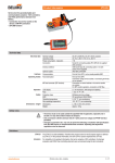
1.1 Introduction
The user manual describes the functions of the Belimo PC Tool. The Belimo
PC-Tool is a PC-based tool for parameterizing Belimo MFT(2), MP, MF, LON and
BF-TopLine actuators, MFT(2), MP and BF-TopLine actuators can be configured
for MP-Bus operation and can be monitored via bus.
This document is designed to present basic information. Since the PC-Tool has a
modular structure, the explanations for specific modules are given in the
individual module documents.
Remark:
The documentation of the individual modules can be accessed through the main
document.
1.2 Information on using the manual
An arrow symbol shows the order of menu commands in sub-menus. For the
function
MP-Channel ` Trigger scan,
select MP-Channel in the main menu and then Trigger scan in the submenu.
This manual uses English terms for control elements frequently encountered in
Microsoft Windows:
Button
Combobox
Radio button
Checkbox
Notes are enclosed in separation lines.
Variant
If a function can be triggered in several ways, variant ways are described in
addition to the recommended way.
4 /51
PC-Tool V3.5 General part, user manual
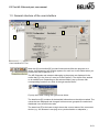
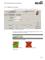
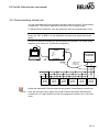
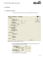
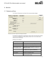
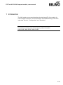
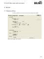
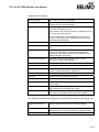
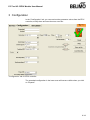
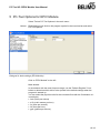
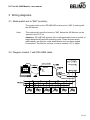
1.3 General structure of the user interface
A
B
D
C
E
User interface PC-Tool
Menu bar [A] and toolbar [B] provide functions that affect the program as a
whole. An explanatory text (tooltip) appears for each icon in the toolbar when you
position the mouse pointer on it.
The MP-Channels and actuators belonging to the project are displayed in the
outline bar [C] in the form of a tree (as in the Explorer). The object to be worked
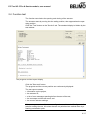
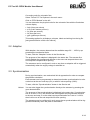
on is marked here. Depending on the selected object, pop-up menus offer
corresponding functions at a click of the right mouse button.
Pop-up menu after clicking the right mouse button
The detail area [D] contains all the detailed information on the object marked. The
values that are displayed and changed in this area are grouped as needed and
distributed over several index tabs.
The status bar [E] at the lower margin shows the current status of the connected
device (e.g.: the actuator is carrying out a synchronization or adaptation.)
5 /51
PC-Tool V3.5 General part, user manual
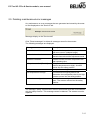
Missing or invalid entries are indicated by a flashing exclamation mark. If you
move the mouse pointer to the exclamation mark, an explanatory text (tooltip)
appears.
Inactive commands are displayed in gray letters (or as gray icons) according to
the Windows standard.
Texts in boxes with a black font on a gray background cannot be changed. You
can mark the contents with the mouse, however, and copy them into the
clipboard with CTRL+C, for example.
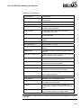
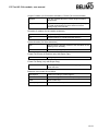
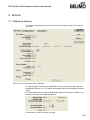
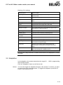
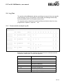
1.4 Modules and actuator types
Multifunctional damper actuators
The following actuator types can be parameterized with the program PC-Tool:
Generation
Type
MP-bus
Sensors
NEW
MP
YES
active, passive, switch
MPL
YES
(see datasheet)
MF
No
(none)
MFT2
YES
active, passive, switch
MFT
YES
active, switch
BF..24TL..
YES
(none)
OLD
The manual is organized according to the application areas for actuators
(modules). Detailed descriptions can be found in the module-specific sections,
e.g. Air module, Water module, Fire & Smoke module, VAV module, EPIV
Module.
VAV controller
The VAV module (VAV = Variable Air Volume) is for operating and
parameterizing the Belimo VAV-Compact controller xMV-D2-MP.
6 /51
PC-Tool V3.5 General part, user manual
2 Getting started with PC-Tool
2.1 Connecting the computer with the actuators
Connect the level converter ZIP-USB-MP to your computer. The connection of
the actuators to the ZIP box is explained in the Appendix. If you use a different
interface than COM1, you must subsequently adapt the setting [Ö 3.3.1 Serial
interface].
For typical wiring diagrams, see Ö 4.4 Typical wiring diagrams
2.2 Starting the program
Click the program icon on your desktop. A start screen appears. Click Start
Belimo PC-Tool (bottom right).
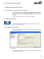
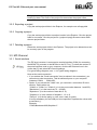
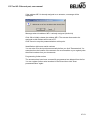
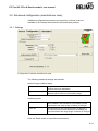
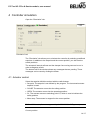
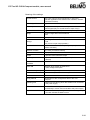
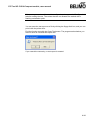
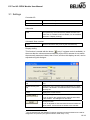
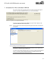
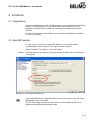
2.3 Adapting PC-Tool options
When you start the program for the first time, a dialog is displayed for adapting
the user-specific settings.
PC-Tool options
Select the desired language in the combobox here. If you change the language,
exit the program and restart it.
7 /51
PC-Tool V3.5 General part, user manual
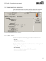
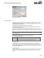
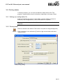
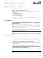
2.4 Creating a new project
To work with the program, you have to create a "project". The dialog for entering
the project data is displayed. Click the radio button "New project".
Creating a new project
The project name, company and user ID must be filled in; all other information is
optional.
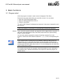
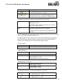
2.5 Setting up the program
The project and the MP-Channel can be seen in the outline bar [C]. The bus is
scanned every 10 seconds by default.
Outline bar [C]
If no actuators are shown after 10 seconds, you should check whether the level
converter ZIP-USB-MP is connected to the right COM interface. Adjust the
settings for the serial interface if necessary [Ö 3.3.1].
8 /51
PC-Tool V3.5 General part, user manual
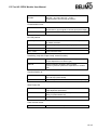
2.6 Displaying actuator parameters
Select the desired actuator in the outline bar [C] by clicking it with the mouse.
The current settings for the actuator are displayed in the detail area [D].
Example of detail area [D] (damper actuator)
2.7 Further actions
Read the descriptions for the following topics in Section 3 Basic functions
Bus scan
Setting the bus address
Parameterization of actuators
Read the details for the application areas of the actuators in the descriptions of
the following modules
Damper actuators (Air module)
VAV controllers
Actuators for fire & smoke dampers (Fire & Smoke module)
Valve actuators (Water module)
9 /51
PC-Tool V3.5 General part, user manual
3 Basic functions
3.1 Program start
After the program is started, a start screen is displayed. Click Start.
Determine the project with which you would like to work. You can either
open one of the last projects listed,
open an existing project from a file, or
create a new project.
The defined MP-Channel is displayed and opened. A bus scan is started for each
MP-Channel.
If only one actuator is connected, it is automatically selected and displayed.
Variant
If you cancel the project selection, the program will be started without a project. In
this case, only the functions Help, File` New project and File ` Open existing
project will be available.
You can also start the program by means of opening a project file: In the
Explorer, double-click a file with the extension .bptpj or on a corresponding file
link.
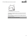
If you create a link to a project file on the desktop, make sure that you do not
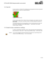
inadvertently move or copy the file instead. You can tell when a link has been
created correctly by the small arrow in the bottom left-hand corner of the file icon.
(If the project file itself, rather than a link to it, is on the desktop then all other files
will be saved there as well.)
In a network environment, the program should be installed on your workstation
and started locally. Special authorizations are required to start the program on
network drives.
10 /51
PC-Tool V3.5 General part, user manual
3.2 Projects
3.2.1 Project data
All user-specific data of the program are administered in the framework of
projects. Each project has a project directory in the file system. The project files
are stored in sub-directories of the project directory.
The storage place of the project files is described in the Appendix.
3.2.2 Creating a new project
Select File `, New Project in the main menu. Enter the new project data in the
dialog. The project name, company and user ID must be filled in; all other
information is optional. Click OK.
Since only one project can be active at a time, the currently displayed project will
be closed and the new project opened.
Variant
You can also create a new project by clicking the New Project icon on the
toolbar [B] or clicking the program icon in the outline bar [C] with the right mouse
button and then selecting New Project.
3.2.3 Opening a project
Select File ` Open Existing Project in the main menu. A list of all project files in
the storage location is displayed.
Mark a project from the list in the dialog or open any given project file (*.bptpj)
with Find.... Click OK.
Since only one project can be active at a time, the currently displayed project will
be closed and the selected project opened instead.
Variant
You can also create a project by clicking on the New Project icon on the toolbar
[B] or clicking the program icon in the outline bar [C] with the right mouse button
and then selecting Open Project.
3.2.4 Changing project data
Click the project in the outline bar [C] to display the project data. The Edit button
(far right) displays a dialog in which you can change the data.
Variant
Click the project in the outline bar [C] with the right mouse button and select
Properties.
Project name and path cannot be changed within the program. However, you can
rename the project file (extension .bptpj) using the Windows Explorer or move
the entire project folder to another location. Afterwards, open the project again.
11 /51
PC-Tool V3.5 General part, user manual
The project folder and project file can have different names – for example for
backing up data. The name of the project file determines the project name.
3.2.5 Exporting a project
Copy the entire project folder in the Explorer, for example onto a floppy disk.
3.2.6 Copying a project
Copy the entire project folder to another location in the Explorer. Give the project
folder a new name. Give the project file (<project>.bptpj) the same name within
the new project folder.
3.2.7 Deleting a project
Delete the entire project folder in the Explorer. The project to be deleted must not
be currently open in the program.
3.3 MP-Channel
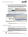
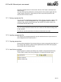
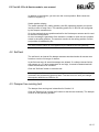
3.3.1 Serial interface
The ZIP level converter is connected to a serial interface (COM) for connecting
the MP/MFT(2) actuator or the MP-Bus to the PC-Tool. To select the number of
the serial interface used on your computer, click the MP-Channel icon in the
outline bar [C] and select MP-Channel settings.
For typical wiring diagrams, see Ö 4.4 Typical wiring diagrams
Now set the serial connection:
If you activate the "Serial connection" box (as shown in the screenshot), you
can select a serial connection. This list shows all ports on your computer
(between COM=1 … COM=255).
Option: If you activate the "Other" box, you can enter a connection ID in the
text box. Valid values are:
"COMx" or "COM:x" or "COM=x" (x is is the port number between 1 and 255).
"Baudrate=x" (x is the baud rate 75...115200).
"Bytesize=x" (x is the number of data bits 5...8).
"Stopbits=x" (x is the number of stopbits 1, 1.5 or 2).
"Parity=x" (x is the the parity no, odd, even, mark or space).
It is only mandatory for the COM port to be specified. Separate the values with
a semicolon (;).
Example:
"COM1;Baudrate=9600;Stopbits=1".
12 /51
PC-Tool V3.5 General part, user manual
MP-Channel settings
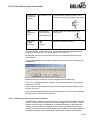
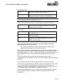
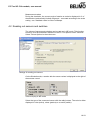
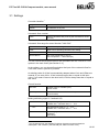
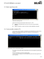
3.3.2 Bus scan
In the bus scan section of the "MP-Channel settings" dialog, you can enter the
time interval for the periodic bus scan in seconds. Permitted values are whole
numbers between 1 and 9999.
The program can address actuators in two basic ways:
In multi-point mode (MP), up to 8 actuators of the types MP / MFT(2) can be
individually digitally addressed.
In point-to-point mode (PP) only a single actuator can be activated. In this case,
the "classic" operating modes are available with response voltage at connection
D5.
The actuators of the MF type can only be connected in PP mode, all others either
in PP or MP mode.
Select the type of bus scan in the bus scan section of the
"MP-Channel settings"dialog:
PP Only
Connection of a single actuator in PP mode
MP / PP
First scan address 1 to 8 in MP mode.
If there is no response in MP mode, switch to PP mode.
Periodic bus scan
The periodic bus scan is active by default. To switch this off, click the MPChannel with the right mouse button and select Interrupt scanning. Afterwards,
you can switch the periodic scan back on again the same way with the menu item
Scan Every xx Seconds.
Manual bus scan
Manually activate an immediate bus scan with the function button F5 ("Update")
as needed. This is possible at any time, even when the periodic bus scan is
active.
13 /51
PC-Tool V3.5 General part, user manual
Variant
You can also select MP-Channel ` Trigger Scan in the main menu or activate
the Trigger scan function by clicking the MP-Channel with the right mouse button.
If more than one actuator responds at the same MP address during a bus scan or
if more than one actuator is connected in PP mode, a bus jam will occur. This
situation is indicated by the program with a corresponding message.
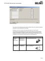
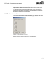
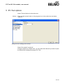
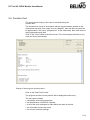
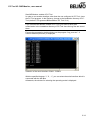
Saving a bus scan overview in a file
The result of a bus scan can be saved in a file for recording. Select "Channel" in
the outline bar to show an enumeration of all found MP nodes with the
corresponding data (address, position, type, description and serial number).
Saving the bus scan overview
Click the right mouse button to open the context menu and choose "Save to file"
for saving the information in a text file.
3.4 Setting the bus address
Each actuator with an MP-Bus interface (valid for all devices with an MP-Bus
interface, e.g. I/O modules, etc.) can be assigned an address which it will use to
communicate on the MP-Bus.
The setting of the bus address can be disabled on certain actuators, e.g. for the
actuator types ...LON and ...ALON (for LONWORKS®).
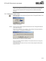
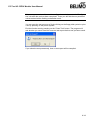
3.4.1 Series addressing of actuators
Click the Address device icon in the toolbar [B].
Variant
Click the MP-Channel with the right mouse button and select Addressing Device.
Or select MP-Channel ` Addressing Device in the main menu.
14 /51
PC-Tool V3.5 General part, user manual
Series addressing
If you want to use something other than the default order, then select the desired
addresses in the comboboxes on the right.
Reading in the serial numbers with acknowledgement on the actuator
Then press the acknowledge button on the actuator that is to receive the first
address. Depending on the type of actuator, this is the manual button, the L/R
change-over switch, the manual control or the S2 button. (If the buttons are not
accessible, enter the serial numbers directly as described below.)
Actuator family Actuator type
Acknowledge function
Actuators
without
spring return
NM24-MFT(2)
AM24-MFT(2)
GM24-MFT(2)
Press manual button once!
Actuators with
spring return
LF24-MFT(2)
AF24-MFT(2)
Move L/R switch back and forth once
(within 4 seconds)!
L
R
15 /51
PC-Tool V3.5 General part, user manual
Actuators for
fire & smoke
dampers
BF(G)24TL-T-ST Turn the manual control for about 1/6 in
direction "Unlock" and release the crank.
Linear
actuators for
valves
NV24-MFT(2)
NVF24-MFT(2)
Actuators of
the New
Generation
...MP
...MF
...ALON
Actuate button S2 (under the housing
cover) once!
S2
NVF24-MFT(2)-E
Actuate the "Address" button
The serial number of the actuator is read out after the acknowledgement and
written into the input box. The cursor jumps to the next line.
Repeat this process for all actuators that are to be addressed and then click
"Set address".
If one of the addresses is already assigned to another actuator, a message will
be displayed:
Message when an address is already assigned (series addressing)
Click Yes to initially release the address. The actuator that used to occupy the
address is set to PP.
If you select No, the actuator will be set to the already assigned address and a
bus jam can occur.
Click Cancel to stop the series addressing at this point. You can now rearrange
the addresses or end the entire process.
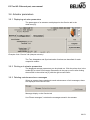
3.4.2 Addressing with known serial numbers
Each MP/MFT(2) actuator is delivered with a label containing its individual serial
number. These serial numbers can be used to assign a PP or an MP1 ... MP8
address to the actuator. An additional, removable label with an identical serial
number is supplied with the actuator. If the actuator is installed at a particular
position in the system, this additional label can be affixed at the same position in
the system diagram. This records where the actuator with the corresponding
16 /51
PC-Tool V3.5 General part, user manual
serial number is located in the building. These serial numbers can be used to
assign the MP1 ... MP8 addresses to the actuators.
You can also fill in the input boxes manually before clicking Set Address, for
example when the buttons of the actuators are not accessible or you regularly
take the serial numbers from your documents.
3.4.3 Resetting actuator addresses
If you want to reset actuators with MP addressing to PP, click to the right of the
MP-Channel and select "De-address Device" in the pop-up menu.
Selection of the addresses to be reset
Mark the addresses whose actuators are to be de-addressed.
17 /51
PC-Tool V3.5 General part, user manual
When the bus scan is set to MP/PP, the de-addressed actuators are no longer
visible in the outline bar [C] as long as there are still actuators with addresses.
If you set several actuators to PP, a bus jam will occur with the bus setting
"PP only".
3.4.4 Addressing a single actuator
Select the actuator in the outline bar [C] and click the "Change MP Address" icon
in the toolbar [B].
Setting a new address
Variant
Click the actuator with the right mouse button and select "Change MP Address"
("MP-Adresse ändern").
Select the new address in the combobox. If the address is already assigned to
another actuator, a message will be displayed:
Message when an address is already assigned
Click Yes to initially release the address. The actuator that used to occupy the
address is set to PP.
If you select No, the actuator will be set to the already assigned address and a
bus jam can occur.
18 /51
PC-Tool V3.5 General part, user manual
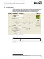
3.5 Selecting a module
All actuators that are active and connected to an MP-Channel are displayed in
the outline bar [C]. Select the desired actuator from this display.
The type of actuator is indicated by the icon:
Icon
Actuator type
Damper actuator
Valve actuator
Window ventilation actuator
Actuator for fire dampers
VAV (Variable Air Volume) controller actuator
THC24-MP
UST-3 I/O module
EPIV Electronic Pressure Independent Valve
Unknown actuator
When an actuator is selected for the first time, the parameters are read out and
displayed in the detail area [D].
In addition, the address for communication on the MP-Channel (MP or PP mode)
and the name of the actuator type are displayed in the outline bar [C].
The complete information for identifying the selected actuator is found in the
header of the detail area [D].
Display of the actuator identification
Note the difference between the current communication mode on the MPChannel and the displayed address. An actuator with the address MP2 can be
activated in PP mode during a bus scan, for example.
19 /51
PC-Tool V3.5 General part, user manual
3.6 Actuator parameters
3.6.1 Displaying actuator parameters
The parameters of an actuator are displayed on the Service tab in the
detail area [D].
Example of the "Service" tab (damper actuator)
The Test, Adaptation and Synchronization functions are described for each
respective module.
3.6.2 Printing out actuator parameters
The displayed actuator parameters can be printed out. Click the printer icon in the
toolbar [B] or select Print Actuator Parameters in the pop-up menu after clicking
the actuator in the outline bar [C] with the right mouse button.
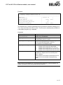
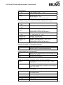
3.6.3 Deleting maintenance/error messages
When an actuator has created and saved maintenance or fault messages, these
are displayed on the Service tab.
Message display on the Service tab
Use "Reset messages", to delete the messages stored in the actuator.
20 /51
PC-Tool V3.5 General part, user manual
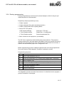
Following messages may appear:
Message
Description
Mechanical travel increased
Expected end stop value for top or bottom
has been overrun.
Mechanical overload
Actuator did not reach set point because an
obstacle has reduced the operating range
Excessive utilisation
Actuator moves to often compared with the
total operating time
(typical relation of active time to operating
time is greater than 20%)
Fail-Safe failed
The Fail-Safe module is defect (e.g Super
Cap module). This message cannot be
deleted. The defect actuator has to be
replaced.
Actuators for fire & smoke dampers have provide a larger scale of messages.
The specific messages are described in the Fire & Smoke module.
21 /51
PC-Tool V3.5 General part, user manual
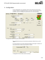
3.7 Configuring an actuator
To change the parameters of an actuator, go to the Configuration tab.
Example of the "Configuration" tab (damper actuator)
The lower area with the basic settings can be displayed with the "More..." button
and hidden again with the "Less" button.
When you change a value in an input box, the box turns yellow:
The status image on the right additionally shows whether all the displayed values
match those stored in the actuator:
Display matches actuator
Values have been changed
Status image
22 /51
PC-Tool V3.5 General part, user manual
Save the changed values in the actuator with the "Set" button underneath the
status image.
You can read out the parameters currently saved in the actuator again with the
"Read" button. Entries for values that you have not previously saved in the
actuator will be lost as a result.
3.7.1 Saving a parameter file
You can store the displayed parameters in a file (with the extension .bptpar) with
"Store to file…" on the "Configuration" tab. The suggested name for the file
consists of the project, the actuator type, the position, the serial number, the
current date and the time of day.
Since the content of the file corresponds to the values displayed on the screen,
you can change individual values and save variants in files without loading them
on the actuator.
The file can only be saved when all values on the screen are valid.
3.7.2 Loading a parameter file
The values of a saved parameter file can be read back into the input screen for
the configuration with "Load from file...".
3.7.3 Copying parameters
Read out the parameters of an actuator that you want to copy and save them in a
file. Change the actuator, load the saved parameters from the file and program
the actuator with the copied values.
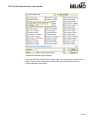
3.7.4 Load factory settings
When a project is created, two folders are created in the parameter directory.
These folders contain the factory settings for all supported actuator types.
23 /51
PC-Tool V3.5 General part, user manual
Parameter files with factory settings
Open the file which matches the actuator type. The settings are loaded into the
input screen for the configuration. Afterwards, store the parameters in the
actuator with the "Set" button.
24 /51
PC-Tool V3.5 General part, user manual
3.8 Parameterizing limited lots
You can parameterize several identical actuators with the function "Parameterize
Limited Lots". The number depends on the power of the voltage supply.
To parameterize limited lots, save the parameter set to be programmed in a file.
With one parameter set, you can only program actuators from the same actuator
family (e.g. MFT or NMV), i.e. the parameter set used must match the actuator
family.
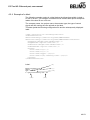
Connect the devices according to the following wiring diagram (for further wiring
diagrams, see clause 4.4 Typical wiring diagrams):
USB
RJ11 (6/4)
Belimo
PC-Tool
Speisung
Power Supply
AC/DC 24V
USB
GND 24 V
ZK2-GEN
white/weiss = GND
blue/blau = 24V
green/grün = MP
GND
MP
....A-MP
…D2-MP
...MFT(2)
....A-MP
…D2-MP
...MFT(2)
....A-MP
…D2-MP
...MFT(2)
....A-MP
…D2-MP
...MFT(2)
....A-MP
…D2-MP
...MFT(2)
....A-MP
…D2-MP
...MFT(2)
Select the desired MP-Channel and click the symbol "Parameterize Limited Lots".
Variant
Click with the right mouse button on the MP-Channel and select Parameterize
Limited Lots. Or select the MP-Channel ` Parameterize Limited Lots in the main
menu.
25 /51
PC-Tool V3.5 General part, user manual
Dialog for parameterizing limited lots
Select the file with the saved parameters in the dialog.
Position the cursor in the first input box for the serial number. Then press the
acknowledge button on the first actuator which should be parameterized. If the
buttons are not accessible, directly enter the serial numbers as described below.
The serial number of the actuator is read out after the acknowledgement and
written into the input box. The cursor jumps to the next line.
Repeat the process for all actuators that are to be parameterized and mark the
checkbox if you want to print labels after parameterization
(see Section 3.9 "Printing labels").
Click Parameterize.
The PC-Tool now asks for the file with the values to be written into the actuators.
The periodic bus scan is stopped for the duration of the parameterization. The
actuators are successively set to the address MP1, programmed and finally set to
PP addressing.
When the bus scan is set to MP/PP, the actuators in the outline bar [C] will not be
visible. If the bus setting PP Only is used, a bus jam will result.
If an error occurs during programming, a corresponding text is displayed in the
"State" column.
26 /51
PC-Tool V3.5 General part, user manual
If the address MP1 is already assigned to an actuator, a message will be
displayed:
Message when the address MP1 is already assigned (limited lot)
Click OK to initially release the address MP1. The actuator that used to be
assigned to this address will be set to PP.
Click Cancel to stop the parameterization at this point.
Identification with known serial numbers
You can also fill in the input boxes manually before you click "Parameterize", for
example when the buttons of the actuator are not accessible or you regularly take
the serial numbers from your documents.
Programming further series
The actuators that have been successfully programmed are deleted from the list.
You can register further serial numbers in the list and then click "Start
parameterization" again.
27 /51
PC-Tool V3.5 General part, user manual
3.9 Printing labels
To identify actuators, you can write self-adhesive labels with the PC-Tool
program. A special printer may be necessary, depending on the type of label.
3.9.1 Setting up a configuration file
Labels are defined per project. To print labels, set place holders (number in
brackets) in the configuration file for the information to be printed.
The structure and storage location of the configuration files are described in the
Appendix.
3.9.2 Printing labels
Select an actuator and click the "Print Label" icon (with an orange background).
Variant
Click an actuator in the outline bar [C] with the right mouse button and select
"Label Printing".
Label printing dialog
28 /51
PC-Tool V3.5 General part, user manual
Select a printer and a configuration file.
Enter the number of identical labels that are to be printed for "Number of labels
per actuator". When parameterizing limited lots, the total number of printed labels
is equal to this value times the number of actuators.
Enter the desired texts {41} – {44} that are to be printed, if necessary. A
maximum of 50 characters are available per text box. In text with consecutive
numbering, a number is entered instead of the place holder "#". This number is
increased by one for each new actuator.
If labels have already been used from a label sheet, you can specify at what label
position the printing should start (for example 4 when 3 labels have been used
from the first row).
Your entries and the selected printer are preserved from one label printing
process to the next (automatic saving). You can empty the input boxes with
Reset Form.
The texts {41} – {44} must be present in the label configuration file in the form of
place holders. Otherwise, they will not be printed out.
3.9.3 Printing labels offline
Labels can still be printed even if no actuator is connected. In this case, only the
information from the project data, the texts entered in the dialog and the current
date can be output. The start number is always used instead of the place
holder #.
Click the "Print label" icon (with gray background).
Variant
Click the project in the outline bar [C] with the right mouse button and select
"Label Printing". Or select Project ` Print Label in the main menu.
For Number of labels per actuator, enter the number of identical labels to be
printed. The number with the placeholder "#" is NOT counted up. The further
procedure is the same for printing actuator labels.
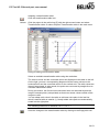
3.10 Transformation tables
Transformation tables are for converting the sensor value into another physical
quantity, for example from resistance (in ohms) to temperature (in °C) for NTC
resistors. Several frequently used transformation tables are supplied with the
program.
Selecting a transformation table
Select a transformation table with the combobox. The corresponding converted
value is displayed underneath the sensor value.
The measured sensor variable in the table must match the selected sensor type:
volts for active sensors, ohms for sensor resistors, on/off for switches.
29 /51
PC-Tool V3.5 General part, user manual
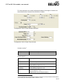
Adapting a transformation table
Click the transformation table icon.
Variant
Click the project in the outline bar [C] with the right mouse button and select
Transformation table. Or select Project `Transformation table in the main menu.
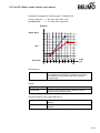
Dialog for editing transformation tables
Select an available transformation table using the combobox.
The sensor values and the converted values are displayed in the table on the left.
On the right, you see a corresponding diagram with the sensor values on the
horizontal axis and the converted values on the vertical axis. The table values are
linearly interpolated; in other words, the points are connected by straight lines to
calculate intermediate values.
During conversion, the first and last connection lines are extended beyond the
range of entered points (extrapolated) so that even sensor values outside of this
range are valid.
You can adapt each value in the table or add new value pairs in the last line,
which is marked with an asterisk (*). Newly added value pairs are automatically
sorted into the right place.
The following holds true for switches: Off = 0, On = 1.
Save the changes to the transformation table by clicking on the floppy disk icon.
30 /51
PC-Tool V3.5 General part, user manual
When you change a transformation table in one project, the changes do not
affect corresponding tables in other projects. However, you can return to the
original project folder from all projects through the entry <Other...> in the
combobox and open the changed table.
Setting up a new transformation table
When the dialog for editing a transformation table is open, you can create a new
table with the "New" icon. Select the physical quantities for the sensor values and
the converted values in the comboboxes above the table. You can also write any
other quantities into the text boxes of the comboboxes.
For the sensor values, only volts, ohms and on/off are meaningful input
quantities, because only these sensor types are supported.
Enter a description in the text box and add new value pairs in the last line of each
table, which is marked with an asterisk (*). A transformation table must have at
least two lines.
For switches, you can define an on/off inversion table with the assignments
0 Æ 1 and 1 Æ 0.
Save the new transformation table by clicking on the floppy disk icon. The name
that you enter in the "Save file as" dialog will be subsequently offered as a
selection in the combobox.
If the name of the new table does not appear in the combobox on the
"Simulation" tab, open the project again.
The new transformation table is not directly available as a selection in the
combobox in other projects. However, you can return to the original project folder
from all projects through the entry <Other...> in the combobox and open the new
table.
Deleting a transformation table
When the dialog for editing a transformation table is open, you can use the
Delete icon to delete a table that has been selected in the combobox.
If the name of the deleted table still appears on the "Simulation" tab in the
combobox, open the project again.
31 /51
PC-Tool V3.5 General part, user manual
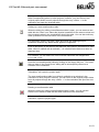
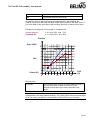
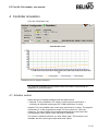
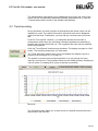
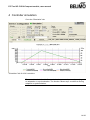
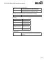
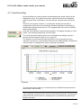
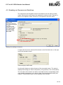
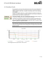
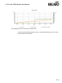
3.11 Displaying recorded trend data
Click the symbol Trend display.
Variant
Click the project in the outline bar [C] with the right mouse button and select
"Trend Recall". Or select Project ` Trend Recall in the main menu.
Trend recall
Select a trend file with the combobox.
Keep the CTRL key pressed and pull the diagram to the left or right with the
mouse in order to display values for other times.
You can use the copy button to insert the diagram into other documents via the
clipboard.
Use the save button to fix the window size of the trend display.
Printing a trend
Click the Print icon or press the key combination CTRL-P.
Variant
In addition to the Print button, you can open a menu with the "down" key. In
addition to printing, this allows you to display a preview or select several files for
printing with "Print multiple".
32 /51
PC-Tool V3.5 General part, user manual
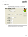
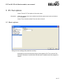
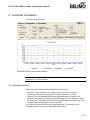
3.12 PC-Tool options
Select Tools`PC-Tool options... in the main menu.
Variant
Click the project in the outline bar [C] with the right mouse button and select PCTool options...
Dialog for basic settings (general)
"Project base path" sets the default directory in the file system, in which the new
project folder will be saved. You can override this information when creating new
projects, however.
When you mark the "Use default", checkbox, new projects will be saved in your
user profile under "My Documents". With the operating system Microsoft
Windows XP (English), this folder is located under
C:\Documents and Settings\<Name>\My Documents.
You can open the folder "My Documents" with the "My Computer" icon.
The language that you select in the combobox will be used the next time that you
start the program.
Under "Log file", you can define whether a separate log file should be created
each month or each week.
Mark the "Activate MP-Monitor" checkbox to monitor the communication with the
actuators with the diagnostic tool.
In addition to "General", the names of the supported modules (actuator families)
are displayed on the left side. Further information on the module-specific settings
is found in the corresponding sections of this manual.
33 /51
PC-Tool V3.5 General part, user manual
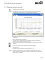
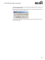
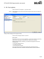
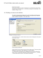
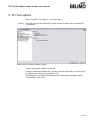
3.13 Log file
All activities with the PC-Tool software that influence the data stored in the
actuator are recorded in a separate log file for every project. The time of each
action is logged.
Configuring the log file
You can create a separate log file for each week or month of a project (default:
File per month). To change this setting, select Tools`PC-Tool options in the main
menu. You can select either ‘File per week' or ‘File per month' under ‘General'.
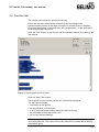
Reading the log file
Click the "Read log file" icon in the toolbar.
Variants
Click the project icon in the outline bar [C] with the right mouse button and select
Read log file. Or select Project `Read log file in the main menu.
Using the combo box ‘Log file', you determine the file to read. The contents of the
log file are displayed in a table in the top section (each action starts a new row).
By clicking a column title, you can sort the table according to the selected
column. By clicking again on the same column title, the sorting direction is
reversed: increasing (A-Z) or decreasing (Z-A).
Details
Click a table row to display details of this action in the bottom section.
You can print the text in the detail area ("Print…" button) or copy it to the
clipboard ("Copy" button) and then paste it into another document.
34 /51
PC-Tool V3.5 General part, user manual
35 /51
PC-Tool V3.5 General part, user manual
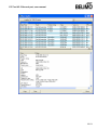
4 Attachment
4.1 Storage locations of files
4.1.1 Project data
The default project is stored as a "Default project" sub-directory in the installation
directory of the program.
The projects are user-specific and are stored as a sub-directory in the user
profile. For an English-language version of Windows, this is
C:\Documents and Settings\<Name>\My Documents\Belimo\PCTool
This directory contains sub-directories with the project names.
4.1.2 Configuration files
The user-specific settings are stored in the user profile under "Application data".
For an English-language version of Windows, this is
C:\Documents and Settings\<Name>\Application Data\Belimo\PCTool
This directory can be "hidden" under Windows. If it is not present, the settings will
be queried upon starting.
36 /51
PC-Tool V3.5 General part, user manual
4.2 Configuration files for printing labels
4.2.1 Storage location
The filenames have the extension *.bptlb. They are saved in the "label
definition" directory for each project. For an English-language version of
Windows, this is
C:\Documents and Settings\<Name>\My Documents\Belimo\PCTool\ <Project>\label definition
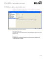
4.2.2 Format
The configuration files for label printing are stored in XML format. You can edit
these files with an editor program, for example "Notepad".
Configuration files for common Avery and Zweckform labels are supplied with the
program.
Example of a configuration file
<?xml version="1.0" encoding="utf-8"?>
<LabelDefinition xmlns:xsd="http://www.w3.org/2001/XMLSchema"
xmlns:xsi="http://www.w3.org/2001/XMLSchema-instance">
<PageSize Height="278" Width="214" />
<PageBorder Top="18" Left="5" />
<LabelSize Height="33" Width="100" />
<LabelBorder Top="5" Left="5" />
<Lines>
<Line Text="" />
<Line Text="{0} / {1}" />
<Line Text="{20}" />
<Line Text="{21}" />
<Line Text="{23}" />
<Line Text="{41} / {42}" />
</Lines>
</LabelDefinition>
37 /51
PC-Tool V3.5 General part, user manual
4.2.3 Boxes
You can adapt the values for the page layout (values in millimeters) for new label
formats.
PageSize
Page size (height and width)
PageBorder
Border width (top and left) = distance from the top left corner of
the first label to the page border
LabelSize
Size of an individual label
LabelBorder
Label border width (top and left) = distance of the lettering from
the label border
In every line element <Line>, you can insert place holders where certain project
and actuator characteristics will be added during printing.
38 /51
PC-Tool V3.5 General part, user manual
{0}
Company name (from project data)
{1}
Project name
{10}
Actuator type
{11}
OEM designation
{12}
Position
{13}
Serial number
{14}
MP address
{20}
Control type Y
{21}
Feedback signal U5
{22}
Range of rotation min – mid – max
{23}
Running time
{24}
Direction of rotation (cw /ccw)
{25}
Bus fail position
{26}
Sensitivity
{27}
Synchronization at
{28}
Torque
{29}
Nominal range
{30}
Conductance
{31}
Vnom
{32}
Vmax
{34}
Vmin
{36}
Control fct.
{37}
Mode
{40}
Printing date
{41}
Text with consecutive numbering
{42}
Freely definable text 1
{43}
Freely definable text 2
{44}
Freely definable text 3
{50}
Switching point S1 in degrees (°)
{51}
Switching point S2 in degrees (°)
{52}
Setting damper free running test
{53}
Valve Size (EPIV-Modul)
{54}
Power Fail Delay (Super Cap)
{55}
Power Fail Position / Power off Position (Super Cap)
You can define up to 50 lines. The program does not check whether the lines fit
on a label.
When you define a new configuration file in a project, this configuration will not be
directly available in other projects. However, you can return to the original project
folder from all projects by using the entry <Other...> in the combobox, and then
use the file.
39 /51
PC-Tool V3.5 General part, user manual
4.2.4 Example of a label
The following example results in a label having the dimensions width x height =
50 mm x 20 mm. The example is intended for an endless label printer that prints
labels of the size 50 mm x 20 mm.
The company name, the project name, the actuator type, the type of control
signal and the running time are printed on the label.
This data yields the following configuration file and the subsequently displayed
label:
<?xml version="1.0" encoding="utf-8"?>
<LabelDefinition
xmlns:xsd="http://www.w3.org/2001/XMLSchema"
xmlns:xsi="http://www.w3.org/2001/XMLSchema-instance">
<PageSize Height="20" Width="50" />
<PageBorder Top="0" Left="0" />
<LabelSize Height="20" Width="50" />
<LabelBorder Top="5" Left="5" />
<Lines>
<Line Text="{0}" />
<Line Text="{1}" />
<Line Text="Type: {10}"/>
<Line Text="{20} Running time: {23}"/>
</Lines>
</LabelDefinition>
Label:
{0}
Belimo Automation AG
Sample
Type: LM24A-MP
Y: Open/Close Running time: 40s
{20}
{1}
{10}
{23}
40 /51
PC-Tool V3.5 General part, user manual
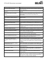
4.3 Troubleshooting and error messages
4.3.1 General
Problem
After the program starts, an MP-Channel is not opened but displayed with the
MP-Channel icon.
Solution
The MP-Channel cannot be opened, for example because the selected serial
interface is assigned to another application. Check whether a modem or a
communication program is using this interface.
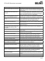
4.3.2 Error messages
Error message
Description
Start adaptation failed.
Communication failure on the MP-Channel or faulty actuator.
Actuator locked for PC-Tool.
The drive has been configured so that it can be neither read
out nor programmed with the PC-Tool.
Summary: Actuator not reachable
Communication failure on the MP-Channel or faulty actuator.
Summary: Actuator run into timeout.
The drive did not respond within the specified time.
Answer has too much data.
Conflict between the actuator and program. The program
library (belipp.dll) may not be up-to-date.
Answer doesn't have enough data.
Conflict between actuator and program. The program library
(belipp.dll) may not be up-to-date.
Command has not enough parameters. Conflict between actuator and program. The program library
(belipp.dll) may not be up-to-date.
Command parameters out of range.
Conflict between actuator and program. The program library
(belipp.dll) may not be up-to-date.
Belimo library error code = ….
Internal fault.
Description is missing
A transformation table must have a description.
Bus Jam
Two or more devices respond to the same address. Readdress the actuators.
This field is required!
This field must have an entry. It is not allowed to remain empty.
There is already an instance running!
The program cannot be started on a computer where it is
already running.
Error while creating the project!
Check whether it is possible to write to the storage location of
the project.
Error while copying default project.
When a new project is created, configuration files and subdirectories are normally copied from the default project in the
installation directory of PC-Tool. The default project has
probably been accidentally deleted, moved or renamed.
Default project directory '…' does not
exist! Please reinstall the application.
When a new project is created, configuration files and subdirectories are normally copied from the default project in the
installation directory of PC-Tool. The default project has
probably been accidentally deleted, moved or renamed.
41 /51
PC-Tool V3.5 General part, user manual
Error message
Description
Command ... unknown by the device
Conflict between actuator and program. The program library
(belipp.dll) may not be up-to-date.
The value must be between … and ….
The entry is not in the permitted range of values.
Invalid data answer from the device.
Conflict between actuator and program. The program library
(belipp.dll) may not be up-to-date.
The difference is smaller than ….
A rule for the minimum difference between two values has
been violated.
The length of the string must not
exceed … characters.
Shorten your entry.
MP-command ... unknown by
PP_Function
Conflict between actuator and program. The program library
(belipp.dll) may not be up-to-date.
A transformation table must have at
least 2 points.
A transformation table must have at least 2 lines to be able to
calculate intermediate values.
Not all parameters written to device
(Note the detailed instructions with the message regarding the
reason for the error.)
Label print failed.
(Note the detailed instructions with the message regarding the
reason for the error.)
Wrong device family … instead of …
When setting the parameters of small batches, an actuator
from another actuator family was connected and does not
match the parameter file.
Wrong transformation table for this
sensor type. It cannot transform from
unit ….
The transformation table does not have the measuring quantity
of the sensor in the first column. Resistance sensors must
convert 'ohm' into the target parameter, for example.
Wrong device connected!
This fault occurs when actuators are changed during
parameterization. Read the parameters out again.
Wrong MP channel: '...'.
The MP-Channel has changed.
Error starting testscript
The test script is invalid.
Label printing error
(Note the detailed instructions with the message regarding the
reason for the error.)
Error loading transformation table
(Note the detailed instructions with the message regarding the
reason for the error.)
Error while loading project file: …
(Note the detailed instructions with the message regarding the
reason for the error.)
Error reading parameter file
(Note the detailed instructions with the message regarding the
reason for the error.)
Error opening Channel ….
(Note the detailed instructions with the message regarding the
reason for the error.)
Error opening file explorer
File Explorer could not be started when displaying MP-Monitor
files.
Error opening MP-Monitor
(Note the detailed instructions with the message regarding the
reason for the error.)
42 /51
PC-Tool V3.5 General part, user manual
Error message
Description
Error while saving test report!
(Note the detailed instructions with the message regarding the
reason for the error.)
Error while processing line … of the
trend file …
The trend file could not be interpreted. It was probably written
manually.
Error: Invalid code for the module
release.
Relates to the entry of the activation code. Please check your
entry. All boxes must be filled-out according to the
requirements.
Error: There is another device on MP1
Address conflict.
Error: Unable to change address to
MP1
Address conflict.
Error: no answer from actuator
Communication failure on the MP-Channel or faulty actuator.
Address ... already set to this device!
Re-addressing re-assigns an already existing address.
Module release code expired!
Please contact your representative for a replacement of the
code.
Character '…' is not allowed (not ISO8859-1)!
Only characters from the Western European character set are
permitted for Description and Position of an actuator (see table
in Section 4.3.3).
No answer (possible bus jam).
Communication problem on the MP-Channel or faulty actuator.
No answer from device.
Communication failure on the MP-Channel or faulty actuator.
No label configuration file chosen.
Please choose a valid label configuration file and print a test
label or uncheck print label after write.
No or empty setup string.
"Other" was selected when setting the communication
parameters, but no connection was specified.
Could not deaddress other device
Address problem. (Note the detailed instructions with the
message regarding the reason for the error.)
Couldn't write to the device!
Communication failure on the MP-Channel or faulty actuator.
Could not find the VRP-M Tool
executable. Would you search for it
now?
Concerns VRP-M controller. The corresponding program could
not be found at the location specified in the PC-Tool options.
Could not find PC-Tool V2.1. Would
you search for it now?
Affects VAV actuators. The old version of the program could
not be found at the location specified in the PC-Tool options.
Error while loading project.
(Note the detailed instructions with the message regarding the
reason for the error.)
MP-Command ... failed.
Conflict between actuator and program. The program library
(belipp.dll) may not be up-to-date. MP command could be
password-protected.
MP-Channel was closed
The MP-Channel was closed during an asynchronously
running function.
Not all data written to the device.
Communication problem during writing of the parameter data,
possibly due to bus jam. Check the connection and addressing
of the actuators. An MP command is password-protected or
the actuator is not familiar with the command.
Configure the path in the options (menu Tools/PC-Tool options
in VRP-M).
43 /51
PC-Tool V3.5 General part, user manual
Error message
Description
Could not read all data from the device. Communication problem while the parameter data was read,
possibly due to bus jam. Check the connection and addressing
of the actuators.
Not all fields have valid values! Can't
write data
One or more input values in the "Configuration" tab is not valid.
Look for a flashing exclamation mark. If you move the mouse
pointer to the exclamation mark, an explanatory text (tooltip)
with the valid range of values will usually appear.
OEM or BELIMO password necessary.
Please contact OEM-Manufacturer
Parameters on the actuator can be protected with a password
against changes. A password is necessary to overwrite them.
Parameter file contains no series
number
When setting the parameters of small batches, the actuator
family is checked by means of the serial number. The
parameter file is old or has been changed manually.
Error opening configuration file
(Note the detailed instructions with the message regarding the
reason for the error.)
Error storing configuration file
(Note the detailed instructions with the message regarding the
reason for the error.)
Plausibility check: Failed. Please check Testing is not started if there are errors in the configuration.
the configuration dialog for further
information.
Problems opening the MP-Channel "...". Error at the interface. Check the communication parameters
and the cabling.
Sending ... to ... returned error ...
Conflict between actuator and program. The program library
(belipp.dll) may not be up-to-date.
Wrong format of serial number
You have made a typing error while manually entering the
serial number. Check the notation of the serial number.
Series number has a wrong format!
You have made a typing error while manually entering the
serial number. Check the notation of the serial number.
Reset alarm messages failed
Communication failure on the MP-Channel or faulty actuator.
Synchronization failed
Communication failure on the MP-Channel or faulty actuator.
The test script cannot be started because
some conditions are not complied.
A certain minimum air flow or system pressure is necessary for
the test. Please check fan and VAV box.
Start test run failed
Communication failure on the MP-Channel or faulty actuator.
New address could not be verified
The serial number is read before and after an actuator is readdressed. These two numbers do not match. Another
actuator probably answers to the programmed address.
Unknown MP-Channel '...'.
The MP-Channel could not be identified.
Invalid or corrupted parameter file '...'
The contents of the file could not be correctly interpreted. The
format may no longer be valid. If possible, read out the
parameters again and save them in a new file.
Invalid Series Number
The entered serial number was not found in any connected
actuator.
Invalid value entered
Refer to the notes about the valid range of values.
Invalid value!
Refer to the notes about the valid range of values.
44 /51
PC-Tool V3.5 General part, user manual
Error message
Description
Unspecific Belimo-Lib error
Internal fault.
Must be greater than zero.
Refer to the notes about the valid range of values.
Must be an integer.
Refer to the notes about the valid range of values.
Summary: Test cannot be executed
due to active forced control
Remove the Y connection with the control signal for the
duration of the test.
Two or more devices respond to the
same address.
Bus jam Re-address the actuators.
45 /51
PC-Tool V3.5 General part, user manual
4.3.3 ISO 8859-1/ANSI character set
Only characters from the ISO 8859-1/ANSI character set are permitted in the "Description" and "Position"
box
Pos
32
33
34
35
36
37
38
39
40
41
42
43
44
45
46
47
48
49
50
51
52
53
54
55
56
57
58
59
60
61
62
63
Char Pos
64
!
65
"
66
#
67
$
68
%
69
&
70
'
71
(
72
)
73
*
74
+
75
,
76
77
.
78
/
79
0
80
1
81
2
82
3
83
4
84
5
85
6
86
7
87
8
88
9
89
:
90
;
91
<
92
=
93
>
94
?
95
Char
@
A
B
C
D
E
F
G
H
I
J
K
L
M
N
O
P
Q
R
S
T
U
V
W
X
Y
Z
[
\
]
^
_
Pos
96
97
98
99
100
101
102
103
104
105
106
107
108
109
110
111
112
113
114
115
116
117
118
119
120
121
122
123
124
125
126
127
The character positions marked with
1)
Single speech mark, low
2)
Double speech marks, low
3)
Single left speech mark
4)
Single right speech mark
5)
Double left speech marks
6)
Double right speech marks
7)
Non-breaking space
8)
Breaking hyphen
Char
`
a
b
c
d
e
f
g
h
i
j
k
l
m
n
o
p
q
r
s
t
u
v
w
x
y
z
{
|
}
~
Pos
128
129
130
131
132
133
134
135
136
137
138
139
140
141
142
143
144
145
146
147
148
149
150
151
152
153
154
155
156
157
158
159
Char Pos
€
160
161
‚ 1)
162
ƒ
163
2)
„
164
…
165
†
166
‡
167
ˆ
168
‰
169
Š
170
‹
171
Œ
172
173
Ž
174
175
176
3)
‘
177
4)
'
178
5)
"
179
6)
"
180
•
181
–
182
—
183
˜
184
™
185
š
186
›
187
œ
188
189
ž
190
Ÿ
191
Char Pos
7)
192
¡
193
¢
194
£
195
¤
196
¥
197
¦
198
§
199
¨
200
©
201
ª
202
«
203
¬
204
8)
205
®
206
¯
207
°
208
±
209
²
210
³
211
´
212
µ
213
¶
214
·
215
¸
216
¹
217
º
218
»
219
¼
220
½
221
¾
222
¿
223
Char
À
Á
Â
Ã
Ä
Å
Æ
Ç
È
É
Ê
Ë
Ì
Í
Î
Ï
Ð
Ñ
Ò
Ó
Ô
Õ
Ö
×
Ø
Ù
Ú
Û
Ü
Ý
Þ
ß
Pos
224
225
226
227
228
229
230
231
232
233
234
235
236
237
238
239
240
241
242
243
244
245
246
247
248
249
250
251
252
253
254
255
Char
à
á
â
ã
ä
å
æ
ç
è
é
ê
ë
ì
í
î
ï
ð
ñ
ò
ó
ô
õ
ö
÷
ø
ù
ú
û
ü
ý
þ
ÿ
are vacant.
46 /51
PC-Tool V3.5 General part, user manual
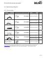
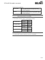
4.4 Typical wiring diagrams
4.4.1 Overview table
Cable
MP level converters and devices
Drawing
Page
Typical wiring diagram 1
48
Typical wiring diagram 2
48
Typical wiring diagram 3
49
ZIP-USB-MP
Typical wiring diagram 4
49
ZIP-USB-MP
Typical wiring diagram 5
50
Typical wiring diagram 6
50
Typical wiring diagram 7
51
Typical wiring diagram 8
51
ZK1-GEN
ZIP-USB-MP
ZK2-GEN
ZIP-USB-MP
ZK6-GEN
ZKS-MP
ZK1-VAV
ZIP-USB-MP
Direct connection
ZIP-RS232
For further wiring examples with miscellaneous connection cables und level converters see
www.belimo.eu | Documentation | Bus- and System-Integration | "Tool connection guide"
47 /51
PC-Tool V3.5 General part, user manual
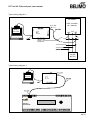
4.4.2 Typical wiring diagrams
Typical wiring diagram 1
USB
RJ11 (6/4)
Belimo
PC-Tool
24V
GND
ZK1-GEN
USB
...A-MF
...A-MP
...D2-MP
...ALON
...D2LON
2
1
Typical wiring diagram 2
~ T
_
RJ11 (6/4)
USB
+
AC 24 V
DC 24 V
ZK2-GEN
Belimo
PC-Tool
MP
GND
white/weiss = GND
blue/blau = not connected/nicht angeschlossen
green/grün = MP
...MFT(2)
...A-MF
...A-MP
...D2-MP
...LON
...ALON
...D2LON
1 2
5
~ T
USB
U5/MP
_ +
48 /51
PC-Tool V3.5 General part, user manual
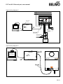
Typical wiring diagram 3
MP-Master
DDC Controller
UK...Gateway
RJ11 (6/4)
USB
ZK2-GEN
Belimo
PC-Tool
GND 24 V MP
USB
GND
white/weiss = GND
blue/blau = not connected/nicht angeschlossen
green/grün = MP
MP
....A-MP
…D2-MP
...MFT(2)
Typical wiring diagram 4
USB
RJ11 (6/4)
Belimo
PC-Tool
ZK6-GEN
USB
RJ11 (6/4)
Optimizer
COU24-A-MP
30
49 /51
PC-Tool V3.5 General part, user manual
Typical wiring diagram 5
UK24LON/EIB
MFT-H
MP-Monitoring
Pos. „MO“
LonTalk
a b
Power
0V 24V n.c.
MP-Com.
0V 24V Y U/MP
USB
Belimo
PC-Tool
3 pol
~T
AC 24 V
_
DC 24 V
+
USB
ZKS-MP
....A-MP
…D2-MP
...MFT(2)
Typical wiring diagram 6
USB
RJ11 (6/4)
Belimo
PC-Tool
NMV-D2M
USB
ZK1-VAV
°°°
50 /51
PC-Tool V3.5 General part, user manual
Typical wiring diagram 7
USB
RJ11 (6/4)
Belimo
PC-Tool
CR24..
USB
°°°
°°°
ZK1-VAV
ZN230-24
AC 230/ 24 V
RS232
Typical wiring diagram 8
Belimo
PC-Tool
AC 230 V
D-Sub
1
2
T
~
_
+
3
T
OFF
1
~
Actuator
ON
U
PP
2
5
RS232
ZIP-RS232
D-Sub
5
.....MFT(2)
U5
MP .....A-MF
.....A-MP
51 /51
PC-Tool V3.5 Air module, user manual
PC-Tool V3.5 Air module
For damper actuators
User Manual
English
1 /21
PC-Tool V3.5 Air module, user manual
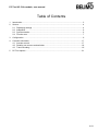
Table of Contents
1
Introduction........................................................................................................................ 3
2
Service............................................................................................................................... 4
2.1 Displaying settings .................................................................................................... 4
2.2 Adaptation ................................................................................................................. 6
2.3 Synchronization......................................................................................................... 6
2.4 Function test.............................................................................................................. 7
3
Configuration ..................................................................................................................... 9
4
Controller simulation........................................................................................................ 17
4.1 Actuator control ....................................................................................................... 17
4.2 Reading out sensors and switches ......................................................................... 18
4.3 Trend recording....................................................................................................... 19
5
PC-Tool options............................................................................................................... 21
2 /21
PC-Tool V3.5 Air module, user manual
1 Introduction
The "Air module" user manual describes the detail area [D] of the Air module.
The documentation is divided according to the three index tabs "Service",
"Configuration" and "Simulation".
3 /21
PC-Tool V3.5 Air module, user manual
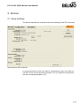
2 Service
2.1 Displaying settings
The Service tab gives an overview of the current settings of the actuator.
Service tab for full-rotation damper actuators
For linear actuators the stroke is displayed instead of the angle of rotation, and
the torque instead of the positioning force.
Service tab for linear actuators (excerpt)
4 /21
PC-Tool V3.5 Air module, user manual
Meaning of the settings
Control signal Y
Type of control
Sensitivity
Response sensitivity and reversal hysteresis of the
control function
Feedback U5
Type of feedback signal
Range
Position range within the mechanical limits
Running time
related to operating range or a fixed angle/stroke of
95°/100mm (with annotation)
Angle of rotation
Programmed rotation range: Min / Mid / Max
(for full-rotation actuators)
Stroke
Programmed stroke range: Min / Mid / Max
(for linear actuators)
Direction of rotation
Clockwise/counterclockwise (for full-rotation
actuators)
Direction of stroke
Up / down (for linear actuators)
Synchronization at
Stop position 0 % or 100 %
Torque
In percent of the maximum torque (for full-rotation
actuators)
Actuating force
In percent of maximum positioning force (for linear
actuators)
Power fail-/Power off Pos.
Actuator position in case of power fail (exists only on
actuators with Super Cap modules)
Power Fail Delay
time delay until actuator drives to power fail position.
(exists only on actuators with Super Cap modules)
Power Fail Count
Number of power Fail counts (exists only on
actuators with Super Cap modules)
Manual button [once]
Function when pressed once
Manual button [twice]
Function when pressed twice
(not present in "New Generation" actuators)
Function table
Assignment of override setting and override function
(only for certain actuators)
Firmware
Software version on the actuator
Config table ID
Identification of the configuration table
Operating time
Number of hours during which the actuator was
connected to the power supply
Active time
Number of hours during which the actuator was
mechanically in motion and connected to the power
supply
Stop & Go ratio
Ratio of active time/operating time in percent. A high
Stop & Go ratio indicates an unstable control.
Running time, range, direction of rotation and stroke are not displayed on certain
actuators.
5 /21
PC-Tool V3.5 Air module, user manual
2.2 Adaptation
In the adaptation, the actuator determines the range 0% ... 100% by approaching
the mechanical limits.
Click the "Adaptation" button on the Service tab.
Variant
You can also trigger the adaptation directly on the actuator. The necessary
buttons for this can be programmed. For example, "Manual button [twice]" can be
assigned the adaptation function.
The progress of the adaptation is displayed in the status line. The actuator first
moves against the programmed direction to the zero stop and then to the end
stop at the full angle of rotation.
Next, the absolute values for a programmed limited angle of rotation range
(minimum, mid-position, and maximum) as well as the feedback signal U5 are
recalculated and displayed.
The adaptation can be blocked in certain actuators.
2.3 Synchronization
In the case of synchronization, a mechanical limit is moved to in order to
determine the absolute range.
For each actuator, it is possible to program whether synchronization will take
place at the zero stop (0%) or at the full angle of rotation/stroke (100%).
Click the "Synchronization" button on the Service tab.
Variant
You can also trigger the synchronization directly on the actuator. The necessary
buttons for this can be programmed. For example, "Manual button [once]" can be
assigned the synchronization function.
The progress of the synchronization is displayed in the status line. With the
setting Synchronization at: Y=0%, the actuator moves against the programmed
direction to the zero stop, and with the setting Synchronization at: Y=100% to the
end stop at the full angle of rotation/stroke.
The synchronization can be blocked in certain actuators.
6 /21
PC-Tool V3.5 Air module, user manual
2.4 Function test
The function test checks for opening and closing.
First of all, the drive moves to the mechanical stop according to the
synchronization position. If the angle of rotation (or stroke) is set to "adapted",
movement takes place to the other stop; with "programmed", on the other hand,
to the programmed range limit.
Click the "Test" button on the Service tab. The standard display is covered by the
test window.
Display of test progress and test report
Click the "Start Test" button.
The progress and the current position are continuously displayed.
The test report contains
information on the project,
the identification of the actuator,
a list of fault messages pending before the start of the test,
the test steps and the test results, and
the current actuator settings.
If the test reports an invalid actuator configuration, go to the "Configuration" tab
after ending the test. The values that are not allowed are marked with a flashing
exclamation point.
7 /21
PC-Tool V3.5 Air module, user manual
You can save the test report as a file by clicking the floppy disk icon, and you can
print it with the printer icon.
End the function test with the "Close Test" button. The program asks whether you
want to save an unsaved test report now.
If you cancel the test early, the actuator will be reset to its original state. No test
report will be created.
8 /21
PC-Tool V3.5 Air module, user manual
3 Configuration
On the "Configuration" tab, you can read out parameter values from the actuator,
change them and save them back to the actuator. The valid ranges for the
parameter values are displayed in parentheses next to the input boxes.
"Configuration" tab for full-rotation damper actuators
Note: Running time, range, direction of rotation and stroke cannot be
programmed on certain actuators and are therefore not displayed.
9 /21
PC-Tool V3.5 Air module, user manual
For linear actuators, the stroke is displayed instead of the angle of rotation and
the stroke direction instead of the direction of rotation.
"Configuration" tab for linear actuators (excerpt)
"Configuration" tab for Super Cap (excerpt)
Actuator number 1
Description
16 characters of any text
Position
16 characters of any text
Control signal Y
3-point
AC voltage, positions: Open / neutral / closed
Open / closed
DC or AC voltage, 2-point
DC 0–10 V
(DC voltage)
Fixed operating range DC 0–10 V
DC 2–10 V
modulating
(DC voltage)
Fixed operating range DC 2–10 V
DC variable
Start (Y=0%) 0.5 ... 30 V
Stop (Y=100%) 2.5 ... 32 V
Range between start and stop at least 2 V
1
Only characters from the Western European character set are permitted for Description
and Position (see General part, table in Section 4.3.3).
10 /21
PC-Tool V3.5 Air module, user manual
PWM 0.02–5 s
Duration of the control pulse (pulse width modulation),
fixed operating range
PWM 0.1–25.5 s
Duration of the control pulse, fixed operating range
PWM 0.59–2.93 s
Duration of the control pulse, fixed operating range
PWM variable
Start (Y=0%) minimum 0.02 seconds
Stop (Y=100%) maximum 50 seconds
VAV 4 +/- 6 V
When this function is selected, the actuator is
parameterized as a VAV actuator and can therefore be
controlled by the VAV controllers VR.. .
Note:
When VAV (6 ± 4 V) is selected, the values for minimum,
maximum, intermediate value, running time and angle of
rotation/stroke are reset to the default values.
4–20 mA
(Direct current)
Fixed operating range DC 4–20 mA
Note:
This selection is only available for certain drives (e.g.
"SunYeh")
mA variable
(Direct current)
The values for start and stop are specified in the actuator
and cannot be changed with the PC-Tool.
Note:
This selection is only available for certain drives (e.g.
"SunYeh")
Feedback U5 (only active when the actuator address is set to PP)
Damper position,
2–10 V
DC voltage measurement signal, fixed range
Damper position,
0.5–10 V
DC voltage measurement signal, fixed range
Damper position,
variable
DC voltage measurement signal
Start 0.5...8.0 V / Stop 2.5 ... 10.0 V
Range between start and stop at least 2 V
Damper position,
4–20 mA
Direct current measurement signal, fixed range
...
Certain actuators can define further feedbacks, which
you cannot change, however.
U5 scaling (only with "New Generation" actuator, MF or MP types)
Start
Position in percent, corresponds to the start value of the
feedback signal
Stop
Position in percent which corresponds to the stop value
of the feedback signal
Angle of rotation (for full-rotation actuators)
Stroke (for linear actuators)
Min
Programmed lower limit of the range
11 /21
PC-Tool V3.5 Air module, user manual
Mid
Mid-position of range
Max
Programmed lower limit of the range
An existing value for Mid is automatically adapted when Min and Max are
entered: If you enter Min, Mid is always larger than or equal to this input value. If
you enter Max on the other hand, Mid is always less than or equal to this value.
Examples of settings for control signal Y / feedback U5
Control signal Y:
Feedback U5 :
3...8 V min: 30%, max : 70%
2...7 V start: 20%, stop: 90%
Position
Open 100%
50%
Y/U5
[V]
Closed 0%
0
5
10
Running time
In seconds
Time needed to pass through the range limited by Min and
Max (the valid range of values for the running time
depends on the actuator type and the passed-through
range).
Note: For actuators with the "constant speed" operating mode, the speed does
not depend on the range passed through. The running time refers to a fixed angle
of 95° for rotary actuators or a fixed stroke of 100 mm for linear actuators.
12 /21
PC-Tool V3.5 Air module, user manual
Angle of rotation (for full-rotation actuators) / Stroke (for linear actuators)
Adapted
from the mechanical limits of certain angle of rotation
range/stroke
Programmed
Angle of rotation range (full-rotation) or stroke (linear),
the valid values depend on the maximum nominal
setting range of the actuator
Direction of rotation (for full-rotation actuators)
cw
Damper opening in the clockwise direction
ccw
Damper opening in counterclockwise direction
Stroke direction (for linear actuators)
open
Upward-opening damper (relative to the orientation of the
lettering on the actuator)
down
Downward-opening damper
Power Fail-/Power off Position (only with Super Cap)
in %
emergency Position at Power Fail
Power Fail Delay (only with Super Cap)
in seconds
time delay until actuator drives to emergency position in
power fail case.
Behavior in the event of bus failure
Last setpoint
Position according to control signal Y
Open
Move to full angle of rotation/stroke (100 %)
Close
Move to zero stop
Close quickly
Close with maximum speed
13 /21
PC-Tool V3.5 Air module, user manual
Sensitivity
Sensitivity
Actuators without Actuators with
spring-return:
spring return:
NM24-MFT(2)
AM24-MFT(2)
GM24-MFT(2)
LF24-MFT(2)
AF24-MFT(2)
1° angle of
rotation
1° angle of
rotation
Actuators of the
new generation
and linear:
..MF
..MP
..LON
Normal
– Response sensitivity:
1%
@ operating range
(SY Æ 2%)
– Reversal hysteresis
2.5° angle of
rotation
2.5° angle of
rotation
2.5%
@ operating range
(SY Æ 3%)
Damped
– Response sensitivity:
2° angle of
rotation
2° angle of
rotation
2%
@ operating range
(SY Æ 5%)
– Reversal hysteresis
5° angle of
rotation
5° angle of
rotation
5%
@ operating range
(SY Æ 6%)
14 /21
PC-Tool V3.5 Air module, user manual
Synchronization at
Y = 0%
Moves to the mechanical limit at zero stop (depending on
the direction of rotation / stroke direction)
Y = 100%
Moves to the mechanical limit at full angle of rotation
(depending on direction of rotation / stroke direction)
Note: When the nominal setting range is set to "programmed", then the
synchronization MUST be carried out at Y=0%.
Torque (for full-rotation actuators) / Positioning force (for linear actuators)
25% ... 100%
Can be set in increments of 25%. 100% corresponds to the
maximum torque / the maximum positioning force for the
actuator type (see nameplate)
Power ON
Synchronization
Moves to a mechanical limit (according to the setting
"Synchronization at")
Adaptation
Moves to both mechanical limits and recalculates angledependent parameters
Nothing
(This option is not available for actuators of the "TOP"
performance class. When switched on, they must always be
adapted or synchronized)
You can programmatically limit the rotation and stroke range at one end by only
changing the minimum or the maximum. If the value of Power ON is set to
"Nothing", then the following holds true:
The mechanical limit that can still be attained within a rotation range
limited at one end will be used for synchronization.
If you set the minimum to a value greater than 0%, the zero stop will no longer be
in the range. In this case, synchronization will take place at the end stop of the
full damper opening (Y = 100%). If, on the other hand, you set the maximum to a
value smaller than 100%, synchronization will take place at the zero stop (Y =
0%).
This is also valid for the case that the nominal setting range is set to
"programmed" and the minimum is equal to 0%: The setting "Power ON: Nothing"
is allowed.
Synchronization when the angle of rotation/stroke is limited at both ends
If the minimum is greater than 0% AND the maximum is smaller than 100%, then
you can select where the synchronization will take place. In this case, it is
necessary to perform synchronization or adaptation when you switch the device
on (the setting "Power ON: Nothing" is considered an error).
If the nominal setting range is set to "programmed" and the minimum is greater
than 0%, then the same rule applies: At least one synchronization must be
programmed.
15 /21
PC-Tool V3.5 Air module, user manual
Manual button [once]/[twice]
Synchronization
Moves to a mechanical limit (according to the setting
"Synchronization at") when the manual button is pressed
once or twice respectively
Adaptation
Moves to both mechanical limits and recalculates angledependent parameters when the manual button is pressed
once or twice respectively
Note:
For "New Generation" actuators (types MF, MP), the function
Manual button [twice] is not available.
Function table for behavior when Y-control signal is missing
No Y-signal: No fct
Condition Y
Reaction
Cable disc.
None
Earthing (GND)
No Y-signal: OPEN
No Y-signal: CLOSED
No Y-signal: STOP
CLOSED
Cable disc.
OPEN
Earthing (GND)
OPEN
Cable disc.
CLOSED
Earthing (GND)
CLOSED
Cable disc.
STOP
Earthing (GND)
STOP
Activate the "Show function table" checkbox in order to show the function table.
For addressed MP actuators selecting a reaction is not possible.
16 /21
PC-Tool V3.5 Air module, user manual
4 Controller simulation
Go to the "Simulation" tab.
Simulation tab for damper actuators
The controller simulation is not possible while the actuator is performing an
adaptation or synchronization.
4.1 Actuator control
Select the type of setpoint definition with the radio buttons.
Setpoint Y (only available in PP mode): Control signal at connection Y
according to selected control type (DC, PWM, open/close, 3-point).
Setpoint Tool (not available with control type open/close or 3-point): The setpoint
is entered in % of the programmed range. 0% is the minimum, 100% the
maximum. The input values are converted and displayed in the units of the
corresponding control signal (volts, milliamps or seconds).
The control is switched off when you click "Motor stop". This function is not
available with the control types open/close and 3-point.
17 /21
PC-Tool V3.5 Air module, user manual
Measurement values
During the simulation, the current angle of rotation or stroke is displayed in % of
the absolute (mechanically limited) range and – converted according to the scale
setting – as a feedback value in volts or milliamps.
4.2 Reading out sensors and switches
The values of sensors and switches can be read out in MP mode. This function,
however, must be activated in advance in the PC-Tool options under "General".
Select Tools ` Options in the main menu.
Settings for reading out sensors
On the Simulation tab, a section with the sensor values is displayed to the right of
the actuator control.
Sensor display in MP mode
Select the type of the connected sensor with the radio buttons. The value is either
displayed in volts (active), ohms (passive) or as on/off (switch).
18 /21
PC-Tool V3.5 Air module, user manual
The transformation table allows you to additionally convert the raw value of the
sensor into the corresponding measuring quantity (temperature etc.). (See the
"Transformation table" section in the General User Manual)
4.3 Trend recording
During simulation, the time progress of the setpoints and actual values can be
displayed in a plot. The values are saved in a trend file and can be displayed
again at a later time. Furthermore, you can add any comment texts you would
like.
In the PC-Tool options "General", you determine whether the trend file is
automatically saved when the recording is finished (checkbox not selected) or
whether the program should ask you. The suggested file name can be modified
before saving the file.
Click the "Trend Record" button during simulation. The display changes to a "flat"
button. The recording stops when you click again.
The Trend View radio buttons allow you to set whether the display is given in
percent of the full range (%) or in volts (V).
The position is queried every second by default. You can change the query
interval in an input box. The permitted values are 0 to 9999 seconds, whereby the
value 0 means "no waiting time" (query as quickly as possible).
Trend plot
The Comment button allows you to enter a text at a defined time and the text is
then saved in the trend file.
19 /21
PC-Tool V3.5 Air module, user manual
If you want to record a trend for more than one hour (long-term trend), enter a
value of at least 2 seconds for the interval. If the interval is shorter, too many data
points will result and the time for correcting the curve between the queries can
become too short.
20 /21
PC-Tool V3.5 Air module, user manual
5 PC-Tool options
Select Tools ` Options in the main menu.
Variant
Click the right mouse button on the program icon in the outline bar and select
"Options".
Dialog for basic settings (Air module)
Select "Air module" on the left.
Using the combo box "Default tab", you can select the index tab you want to open
by default when starting the program PC-Tool.
21 /21
PC-Tool V3.5 Fire & Smoke module, user manual
PC-Tool V3.5 Fire & Smoke module
For fire damper actuators
User Manual
English
1 /17
PC-Tool V3.5 Fire & Smoke module, user manual
Table of Contents
1
Introduction........................................................................................................................ 3
2
Service............................................................................................................................... 4
2.1 Displaying settings .................................................................................................... 4
2.2 Damper free running test .......................................................................................... 5
2.3 Adaptation ................................................................................................................. 5
2.4 Function test.............................................................................................................. 6
2.5 Deleting maintenance/error messages ..................................................................... 7
3
Configuration ..................................................................................................................... 8
3.1 Basic configuration.................................................................................................... 8
3.2 Advanced configuration (manufacturer view)............................................................ 9
3.2.1 Settings ........................................................................................................ 9
3.2.2 Program ..................................................................................................... 10
3.2.3 Parameter file............................................................................................. 10
3.2.4 Factory programming ................................................................................. 12
4
Controller simulation........................................................................................................ 14
4.1 Actuator control ....................................................................................................... 14
4.2 Self-test ................................................................................................................... 15
4.3 Damper free running test ........................................................................................ 15
5
PC-Tool options............................................................................................................... 16
5.1 Basic options........................................................................................................... 16
5.2 Advanced options (manufacturer view)................................................................... 17
2 /17
PC-Tool V3.5 Fire & Smoke module, user manual
1 Introduction
The "Fire & Smoke module" user manual describes the detail area [D] of the fire
& smoke module. The documentation is structured according to the three tabs
"Service", "Configuration" and "Simulation".
3 /17
PC-Tool V3.5 Fire & Smoke module, user manual
2 Service
2.1 Displaying settings
The "Service" tab gives an overview of the current actuator settings.
"Service" tab for BF-TopLine fire damper actuators
No settings are displayed for motorization solutions with conventional fire damper
actuators and a BKN230-24-1MP gateway. Please refer to the actuator data
sheets for more information.
Meaning of the settings
Nominal range
Range of rotation within the mechanical end stops
Running time
Time needed to cover the full range of rotation
Switch S1
Switching point for the safety position (in ° and %)
Switch S2
Switching point for the operating position (in ° and %)
Minimal adaption range
Safety limit to prevent adaptations if dampers are
blocked (in ° and %)
Damper free running test
Values for the automatic test in the operating position (values for 180° types in parentheses)
Firmware
Software version installed on the actuator
Config table ID
Identifies the configuration table
Operating time
Number of hours for which the actuator was connected to the power supply
4 /17
PC-Tool V3.5 Fire & Smoke module, user manual
Active time
Number of hours for which the actuator was mechanically in motion and connected to the power
supply
2.2 Damper free running test
The damper free running test checks the actuator's ability to turn from the operating position toward the safety position. Only the configured range is tested, to
prevent complete closure of the damper. The test is repeated after 24 hours.
The damper free running test is suitable for all applications in which the ventilation system is not allowed to be switched off in order to carry out a full damper
test.
Click the "Damper free running test" button on the "Service" tab to start the test
manually.
The damper must be in the operating position and the damper free running test
must not be deactivated.
2.3 Adaptation
Adaptation is when the actuator determines the 0% ... 100% range by approaching the mechanical end stops.
Click the "Adaption" button on the "Service" tab.
The progress of the adaptation is displayed in the status bar. The actuator starts
by moving into the safety position, then approaches the stop in the operating position. The maximum angle of rotation reached is stored in the actuator.
The absolute values for switching points S1 and S2 are then recalculated.
It is important to ensure that the damper blade reaches the mechanical end stops
during the adaptation (visual monitoring of the damper).
5 /17
PC-Tool V3.5 Fire & Smoke module, user manual
2.4 Function test
The function test checks the opening and closing of the actuator.
The actuator starts by moving into the safety position, then approaches the operating position.
Click the "Test" button on the "Service" tab. The standard display is hidden by the
test window.
Test progress and test report display
Click the "Start test" button.
The progress and the current position are continuously displayed.
The test report contains
Information on the project,
the actuator ID,
a list of error messages pending before the start of the test,
the test steps and the test result, and
the current actuator settings.
If the test reports an invalid actuator configuration, switch to the "Configuration"
tab after ending the test. All values that are not permitted are marked there by a
flashing exclamation point.
6 /17
PC-Tool V3.5 Fire & Smoke module, user manual
2.5 Deleting maintenance/error messages
Any maintenance or error messages that are generated and stored by the actuator are displayed on the "Service" tab.
Message display on the "Service tab"
Click "Reset messages" to delete all messages stored in the actuator.
The following messages are displayed:
Message
Description
Mechanical travel increased
Expected end stop value for top or bottom
has been overrun (adapted range)
Mechanical overload
Actuator did not reach setpoint because an
obstacle has reduced the adjustment travel
Excessive utilization
Actuator moves too often compared to the
total operating time
Safety relevant fault [Details]
Safety relevant fault in the actuator (e.g.
ambient temperature too high). Actuator
moves into the safety position
Damper test error
Damper free running test revealed an error
Duct temperature too high
Thermoelectrical tripping device has
detected a duct temperature that is too high.
Actuator moves into the safety position
Smoke detector tripped
Contact for connecting a smoke detector is
open. The actuator moves into the safety
position.
The message "Safety relevant fault" refers to an actuator fault that could interfere
with the safety function. This message cannot be deleted. The actuator must be
replaced.
7 /17
PC-Tool V3.5 Fire & Smoke module, user manual
3 Configuration
3.1 Basic configuration
On the "Configuration" tab, you can read the parameter values stored in the actuator, change them, and re-store them in the actuator. The valid ranges for the
parameter values are shown in parentheses next to the input fields.
"Configuration" tab
Actuator identification 1
Designation
Any 16 characters
Position
Any 16 characters
Damper free running test
Deactivated
Automatic test function deactivated
5°/7 s (10°/7 s)
A damper free running test is carried out every 24 hours
with the specified test criteria (range of rotation, time
limit).
The values shown in parentheses apply to actuators with
a 180° angle of rotation.
10°/10 s (20°/10 s)
20°/20 s (40°/20 s)
The "Damper free running test" setting is not supported by the BKN230-24-1MP
gateway.
1
Only characters in the Western European character set are allowed in the designation
and location (see General part).
8 /17
PC-Tool V3.5 Fire & Smoke module, user manual
3.2 Advanced configuration (manufacturer view)
Additional configuration parameters (protected by a release code) are
available for fire damper manufacturers and authorized partners.
3.2.1 Settings
"Configuration" tab with manufacturer view
The following additional settings are possible:
Nominal range (rotation angle)
Adapted
Range of rotation is determined by the fire damper's mechanical end stops (adaptation)
Programmed
Rotation angle range can be selected within the limits
defined by the maximum nominal setting range
Switching points
Switch S1
Switching point for the safety position in degrees (°); this
value is stored in the actuator as a percentage (%) and
recalculated if the range (angle of rotation) is changed
Switch S2
Switching point for the operating position in degrees (°);
this value is stored in the actuator as a percentage (%)
and recalculated if the range (angle of rotation) is changed
Click the "Read" button to reload the actuator data.
9 /17
PC-Tool V3.5 Fire & Smoke module, user manual
3.2.2 Program
Click the "Program" button to store the new settings in the actuator.
Alternative
Alternatively, you can press function key F9.
The rotation angle range of the actuator is normally determined by adaptation
(Range: Adapted). If the "With adaption" checkbox is selected, the final programming step is to start the adaptation.
If the actuator has already been adapted and you simply want to change a setting, this checkbox can be deselected.
The programming status is indicated by a traffic light (yellow, green, red) and an
explanatory text.
Programming sequence:
c
Connect the actuator
d
Set the parameters
e
Press "Program" (F9)
…Wait until programming has finished (including adaptation)…
f
Check the programming status
g
Print labels (optional)
h
Remove the actuator
For factory programming, refer to Section 3.2.4
3.2.3 Parameter file
The fixed configuration settings for each damper type can be saved to a parameter file to speed up the programming of several actuators.
The respective input fields will have a yellow background when you load these
values by clicking the "Load parameter file (F2)" button.
Alternative
Alternatively, you can press function key F2.
The individual values (e.g. Position) can be changed before you start programming.
10 /17
PC-Tool V3.5 Fire & Smoke module, user manual
Example:
// BELIMO PC-Tool
// Company: Damper Manufacturer XY
// ¯¯¯¯¯¯¯¯¯¯¯¯¯¯¯¯¯¯¯¯¯¯¯¯¯¯¯¯¯¯¯¯¯¯¯¯¯¯¯¯¯¯¯¯¯¯¯¯¯¯¯¯¯¯¯¯¯¯¯¯¯
OEMString
; Product XY
;
PositionString
;
;
MP_Set_Switch
;
1000; 9000;
MP_Set_Operating_Range
;
0;
MP_Set_Extended_Functions
;
11;
MinMaxOperatingRange
;
8800; 9200;
The easiest way to create a parameter file is to select the required settings in PCTool, then save them with "Store to file". The file can be subsequently modified in
a text editor program (e.g. Notepad).
Keywords
OEMString
Designation, any 16 characters
PositionString
Position, any 16 characters
MP_Set_Switch
Switching points S1 and S2 in percent with two
decimal places (1000 Æ 10.00%)
MP_Set_Operating_Range
Programmed range (angle of rotation) in degrees
with two decimal places (9000 Æ 90.00°);
0 corresponds to the adapted range
MP_Set_Extended_Functions Extended functions, possible values:
0:
Damper free running test deactivated
11:
Damper free running test 5°/7 s (10°/7 s)
26:
Damper free running test 10°/10 s (20°/10 s)
42:
Damper free running test 20°/20 s (40°/20 s)
MinMaxOperatingRange
Limit values (angle of rotation) after programming
(adaptation) in degrees with two decimal places
(8800 Æ 88.00°)
These values are not stored in the actuator but are
used by PC-Tool to evaluate the programming
status.
After defining a parameter file, you should save it with the "Write protected" attribute to prevent it from being inadvertently modified.
11 /17
PC-Tool V3.5 Fire & Smoke module, user manual
3.2.4 Factory programming
Factory programming is carried out for several dampers, which is why an optimized sequence is recommended.
Preparatory steps (required only once):
Create a project
Create parameter files (with overwrite protection)
Create a configuration file for printing labels
Set the PC-Tool options
MP channel settings:
Scan type = "PP only"
Fire & Smoke module:
Default tab = "Configuration"
Fire & Smoke module:
Select the parameter file
Save a shortcut to the project on your desktop
The PC-Tool is opened by double-clicking the project shortcut. The project is
opened directly and a bus scan starts immediately. Only one actuator at a time is
allowed to be connected to PC-Tool. As soon as PC-Tool detects an actuator, it
scans it and automatically opens the "Configuration" tab.
Before programming a batch of dampers please make sure the right parameter
file is open and the "With adaption" checkbox is selected correctly.
Programming sequence
c
Connect the actuator
d
Click "Load parameter file (F2)"
e
Check the parameters (e.g. Position) and change them if necessary
f
Click "Program (F9)"
…Wait until programming has finished (including adaptation)…
g
Check the programming status
h
Print labels (optional)
i
Remove the actuator
The adaptation process can take a few minutes. It is therefore best to program a
group of actuators in two stages:
12 /17
PC-Tool V3.5 Fire & Smoke module, user manual
After starting the adaptation, carry out steps 1 to 4 for the other actuators (PCTool does not need to be connected in order to finish the adaptation).
Reconnect all programmed actuators when the adaptation has finished and
carry out steps 5 to 7.
PC-Tool has no way of knowing whether an actuator is already programmed. You
are therefore advised to test the operating range with the narrowest possible limit
values (MinMaxOperatingRange, refer to Section 3.2.3).
13 /17
PC-Tool V3.5 Fire & Smoke module, user manual
4 Controller simulation
Open the "Simulation" tab.
"Simulation" tab
The "Simulation" tab allows you to simulate the controller by selecting predefined
setpoints. In addition to the setpoint and the current position, you also see the
switch positions.
The actuator's internal self-test and the damper free running test can be run in
order to diagnose a fault.
The bottom half of the window shows any messages that are pending. These
messages can be reset by clicking the button.
4.1 Actuator control
Select the setpoint definition method with the radio buttons.
Set point: The setpoint is not defined by the program. The last stored actuator
setpoint is used.
CLOSE: The actuator moves into the safety position.
OPEN: The actuator moves into the operating position.
S1: The actuator moves to switching point S1, which is used to indicate the
safety position.
Motor stop: The actuator is stopped in the current position.
"S1" and "Motor stop" are not supported by the BKN230-24-1MP gateway.
Current position
14 /17
PC-Tool V3.5 Fire & Smoke module, user manual
In addition to the setpoint, you also see the current position. Both values are
shown in degrees (°).
Switch position display
The switch positions S1 (safety position) and S2 (operating position) are visualized by means of lamp icons. The switching points for S1 and S2 are configured
by the damper manufacturer.
Sn is the mechanical zero position switch for the fire damper actuator and is used
to check the end position.
An error message is generated if the actuator is unable to close the zero position
switch in the safety position. The actuator remains in the safety position until the
end position is indicated by Sn.
The zero position switch is not supported by the BKN230-24-1MP gateway.
4.2 Self-test
The self-test is an internal fire damper actuator test that checks all actuator test
functions over the full range of rotation.
In the first test step, all stored messages are deleted. If a safety-relevant fault is
still present (e.g. if a duct temperature is too high), it cannot be deleted and will
cause the self-test to be canceled.
Click the "Self-test" button to start the test.
If the setpoint definition method selected for the actuator is CLOSE, the self-test
is stored in the actuator but does not start. The test is not run until you change
the setpoint definition to OPEN or S1.
4.3 Damper free running test
The damper free running test is described in Section 2.2.
Click the "Damper free running test" button to start the test manually. The damper
must be in the operating position.
15 /17
PC-Tool V3.5 Fire & Smoke module, user manual
5 PC-Tool options
Select Tools ` PC-Tool options in the main menu.
Alternative
Click the program icon in the outline bar with the right mouse button and select
PC-Tool options.
Select "Fire & Smoke module" from the list on the left.
5.1 Basic options
Dialog for basic settings (fire protection module)
Depending on the most frequent usage of the program’s PC-Tool, use the “Default tab” combobox to select which tab will open by default when the program is
started.
16 /17
PC-Tool V3.5 Fire & Smoke module, user manual
5.2 Advanced options (manufacturer view)
Additional options (protected by a release code) are available for fire damper
manufacturers and authorized partners.
Advanced settings dialog (fire protection module)
Start adaption after write
This value determines the basic setting of the "With adaption" option on the "Configuration" tab.
Parameter file
The specified file is selected by default as the "Parameter file" whenever the
"Configuration" tab is opened.
17 /17
PC-Tool V3.5 VAV-Compact module, user manual
PC-Tool V3.5 VAV-Compact module
For VAV controller
User Manual
English
1 /20
PC-Tool V3.5 VAV-Compact module, user manual
Table of Contents
1
Introduction........................................................................................................................ 3
2
Service............................................................................................................................... 4
2.1 Displaying settings .................................................................................................... 4
2.2 Convert units for volumetric flow ............................................................................... 6
2.3 Adaptation ................................................................................................................. 6
2.4 Synchronization......................................................................................................... 6
2.5 Function test.............................................................................................................. 7
3
Configuration ..................................................................................................................... 9
3.1 Settings ................................................................................................................... 10
3.2 Seal bit .................................................................................................................... 13
3.3 Reset to basic manufacturer settings...................................................................... 13
4
Controller simulation........................................................................................................ 14
4.1 Actuator control ....................................................................................................... 15
4.2 Test ......................................................................................................................... 15
4.2.1 Test scripts................................................................................................. 16
4.3 Reading out sensors and switches ......................................................................... 17
4.4 Trend recording....................................................................................................... 18
5
PC-Tool options............................................................................................................... 20
2 /20
PC-Tool V3.5 VAV-Compact module, user manual
1 Introduction
The VAV module user manual describes the detail area [D] of the module for
VAV-Compact controllers. The documentation is divided according to the three
index tabs "Service", "Configuration" and "Simulation".
Note
For function and wiring, see VAV-Compact product information
LMV-D2-MP, NMV-D2-MP, SMV-D2-MP
3 /20
PC-Tool V3.5 VAV-Compact module, user manual
2 Service
2.1 Displaying settings
The Service tab gives an overview of the current settings of the VAV-Compact
controller.
Service tab for full-rotation VAV controllers
The general part of this manual describes how you can print out the controller
parameters [Section 3.6.2.] or delete maintenance and fault messages [Section
3.6.3].
For linear actuators the stroke is displayed instead of the angle of rotation, and
the torque instead of the positioning force.
Service tab for linear actuators (excerpt)
4 /20
PC-Tool V3.5 VAV-Compact module, user manual
Meaning of the settings
Control function
VAV-CAV (volume control equipment) or open loop
operation (operation with external VAV controller, actuator
and sensor function)
Control signal Y
Type of control
Sensitivity
Response sensitivity and reversal hysteresis of the
control signal (only for control function "Open Loop")
Feedback U5
Type of feedback signal (conventional operation)
Range
Position range within the mechanical
limits
Conductance
Box-specific parameter, set by the manufacturer
Volumetric flow
settings
Operating volumetric flow settings: V'nom / V'max / V'min /
V'mid
(only V'nom in open loop operation)
Direction of rotation
Clockwise/counterclockwise opening dampers (for fullrotation actuators)
Direction of stroke
Up / down (for linear actuators)
Synchronization at
Stop position 0 % or 100 %
Torque
In percent of the maximum torque
Actuating force
In percent of maximum positioning force (for linear
actuators)
Behavior in the event of
bus failure
Behavior in the event of a communication failure
Power ON
Behavior when system is switched on
or after voltage interruption
Manual button [once]
Function when gearing latch button is pressed
CAV function
Mechanical stops: Standard or compatible with NMV-D2M
Firmware
Software version of the VAV-Compact
Config table ID
Identification of the configuration table of the VAVCompact
Operating time
Number of hours during which the actuator was connected
to the power supply
Active time
Number of hours during which the actuator was
mechanically in motion and connected to the power supply
Stop & Go ratio
Ratio of active time/operating time in percent. A high Stop
& Go ratio indicates unstable control
5 /20
PC-Tool V3.5 VAV-Compact module, user manual
2.2 Convert units for volumetric flow
Select Tools ` PC-Tool options... in the main menu.
Click the "VAV-Compact module" on the left.
With the Volume display combobox, you determine the physical units for the
volumetric flow
m³/h (cubic meters per hour)
l/s (liters per second)
cfm (cubic feet per minute).
This setting is for all displays, printouts, labels and writing to the log file [see
General part of this manual].
2.3 Adaptation
In the adaptation, the actuator determines the range 0% ... 100% by approaching
the mechanical limits.
To start, click the "Adaptation" button on the Service tab.
The progress of the adaptation is displayed in the status line. The actuator first
moves against the programmed direction to the zero stop and then to the end
stop for a completely opened damper.
The actuators can be configured so that when the supply voltage is switched on
the adaptation is automatically triggered.
The adaptation can be blocked in certain actuators.
2.4 Synchronization
In the case of synchronization, a mechanical limit is approached in order to
calibrate the position calculation.
For each actuator, it is possible to program whether synchronization will take
place at the zero stop (0%) or when the damper is completely opened (100%).
To start, click the "Synchronization" button on the Service tab.
Variant
You can also trigger the synchronization directly on the actuator by pressing the
gearing latch button.
The progress of the synchronization is displayed in the status line. With the
setting Synchronization at: Y=0%, the actuator moves against the programmed
direction to the zero stop, and with the setting Synchronization at: Y=100% to the
end stop where damper is completely opened.
The actuators can be configured so that when the system is switched on, the
synchronization is automatically triggered.
The synchronization can be blocked in certain actuators.
6 /20
PC-Tool V3.5 VAV-Compact module, user manual
2.5 Function test
The function test checks for opening and closing of the damper.
First of all, the drive moves to the mechanical stop according to the
synchronization position. If the range is set to "adapted", movement takes place
to the other stop; with "programmed", on the other hand, to the programmed
range limit.
Click the "Test" button on the Service tab. The standard display is covered by the
test window.
Display of test progress and test report
Click the Start test button.
The progress and the current position are continuously displayed.
The test report contains
information on the project,
the identification of the VAV-Compact controller,
a list of fault messages pending before the start of the test,
the test steps and the test results, and
the current controller settings.
7 /20
PC-Tool V3.5 VAV-Compact module, user manual
If the test reports an invalid controller configuration, change to the "Configuration"
tab after ending the test. The values that are not allowed are marked with a
flashing exclamation point.
You can save the test report as a file by clicking the floppy disk icon, and you can
print it with the printer icon.
End the function test with the Close Test button. The program asks whether you
want to save an unsaved test report now.
If you cancel the test early, no test report is created.
8 /20
PC-Tool V3.5 VAV-Compact module, user manual
3 Configuration
In the "Configuration" box, parameter values can be read out from the VAVCompact controller, changed and stored in a text file. The valid ranges for the
parameter values are displayed in parentheses next to the input boxes.
"Configuration" tab for full-rotation VAV controllers
The extended input boxes in the bottom area become visible when you click
"More".
For linear actuators, the stroke is displayed instead of the angle of rotation and
the stroke direction instead of the direction of rotation.
"Configuration" tab for linear actuators (excerpt)
9 /20
PC-Tool V3.5 VAV-Compact module, user manual
3.1 Settings
Controller identifier 1
Designation
16 characters of any text
Position
16 characters of any text
Volumetric flow, nominal
V'nom
Nominal volumetric flow (is set by the manufacturer of the
VAV box)
Volumetric flow range for control function "VAV-CAV"
V'min
Lower limit of operating volumetric flow setting
V'max
Upper limit of operating volumetric flow setting
V'mid
CAV level between V'min and V'max
Shut-off device
sets V'min permanently to 0 m³/h
(shut-off operation – closed damper)
You can convert the physical units for the volumetric flow via Tools ` PC-Tool
options in the main menu [see Section 2.2.].
In the options, you can also define whether the input of the volumetric flow for
V'min and V'max in percent is possible.
An existing value for V'mid is automatically adapted when V'min and V'Max are
entered: If you enter V'min, V'mid is always larger than or equal to this input
value. If you enter V'max on the other hand, V'mid is always less than or equal to
this value.
Control function
VAV-CAV
Constant (CAV) or variable (VAV)
volume control
Open loop
Operation with external VAV controller (actuator and
sensor function)
Mode (positioning signal Y / feedback U5)
0 ... 10 V
Sets positioning signal Y = 0 … 10 V,
feedback U5 = volumetric flow, 0 … 10 V
2 ... 10 V
Sets positioning signal Y = 2 … 10 V,
feedback U5 = volumetric flow, 2 … 10 V
others
Positioning signal Y and feedback U5 are defined
separately
(see below)
1
Only characters from the Western European character set are permitted for
"Description" and "Position" (see General part, table in Section 4.3.3).
10 /20
PC-Tool V3.5 VAV-Compact module, user manual
Control signal Y
0 … 10 V
Fixed operating range 0 … 10 V
2 … 10 V
Fixed operating range 2 … 10 V
Variable
Start (Y=0%) 0 ... 8 V
Stop (Y=100%) 4 ... 32 V
Range between start and stop at least 2 V
Feedback U5 (only active when the actuator address is set to PP)
Damper position
0 … 10 V
Damper position 0 … 10 V
Damper position
2 … 10 V
Damper position 2 … 10 V
Damper position
variable
Feedback, damper position
Start 0 ... 8.0 V / Stop 2 ... 10.0 V
Range between start and stop at least 2 V
Volumetric flow
0 … 10 V
Feedback, volumetric flow
0 … 100% V'nom = 0 … 10 V
Volumetric flow
2 … 10 V
Feedback, volumetric flow
0 … 100% V'nom = 2 … 10 V
Volumetric flow
variable
Feedback, volumetric flow 0 … 100% V'nom
Start 0 ... 8.0 V / Stop 2 ... 10.0 V
Range between start and stop at least 2 V
Direction of rotation (for full-rotation actuators)
cw
Damper opening in the clockwise direction
ccw
Damper opening in counterclockwise direction
Stroke direction (for linear actuators)
open
Upward-opening damper (relative to the orientation of the
lettering on the actuator)
down
Downward-opening damper
Range (for full-rotation actuators) / Stroke (for linear actuators)
Adapted
from the mechanical limits of certain angle of rotation
range/stroke
Programmed
Angle of rotation range (full-rotation) or stroke (linear),
the valid values depend on the maximum nominal setting
range of the actuator
Behavior in the event of bus failure
Last setpoint
Volumetric flow according to the last received setpoint
from the MP master
Open
Move to full angle of rotation/stroke (100%)
Close
Move to zero stop
Min / V'min
V'min volume
Max / V'max
V'max volume
11 /20
PC-Tool V3.5 VAV-Compact module, user manual
Sensitivity (for "open loop" control function only)
Normal
Normal response sensitivity and reversal hysteresis
(values depend on the actuator type)
reduced
Reduced response sensitivity and increased
reversal hysteresis (values depend on the actuator type)
Synchronization at
Y = 0%
Approach of mechanical limit at zero stop
(damper closed)
Y = 100%
Approach of the mechanical limit with damper
completely opened
Torque (for full-rotation actuators) / Positioning force (for linear actuators)
25% ... 100%
Can be set in increments of 25%. 100% corresponds to
the
maximum torque / the maximum positioning force for the
actuator type (see nameplate)
CAV function
Standard
Mechanical stops:
• Damper closed
• V'min
• V'max
• Damper open
NVD-D2M compatible The CAV levels correspond to the predecessors
NVD-D2M:
• Damper closed
• V'min
• V'mid
• V'max
• Damper open
Power ON
Adaptation
Moves to both mechanical limits and recalculates angledependent parameters
Synchronization
Moves to a mechanical limit (according to the setting
"Synchronization at")
Nothing
(This option is not available for actuators of the "TOP"
performance class. When switched on, they must always
be adapted or synchronized)
Gearing latch
Synchronization
(fix for VAV-Compact actuators)
Note
For function and wiring, see VAV-Compact product information
LMV-D2-MP, NMV-D2-MP, SMV-D2-MP
12 /20
PC-Tool V3.5 VAV-Compact module, user manual
3.2 Seal bit
In each actuator, volumetric flow settings are pre-programmed and are protected
with an electronic seal, the so-called "seal bit".
Symbol for intact seal bit
As soon as the value V'min, V'mid or V'max is changed on the system, the seal
bit is "broken". In this case, the status screen no longer displays the symbol for
the seal bit.
The specified values from the manufacturer can be reactivated at any time with
the function "Resetting to basic OEM settings ..." (see below). The seal bit
remains broken, however.
3.3 Reset to basic manufacturer settings
In order to reactivate the values for V'min, V'max and V'mid pre-programmed by
the manufacturer, select File 4 Reset to basic OEM settings... in the main menu.
Variant
You can also trigger this function with the F6 function key or by clicking on the
"Reset to basic OEM settings..." icon on the toolbar.
13 /20
PC-Tool V3.5 VAV-Compact module, user manual
4 Controller simulation
Go to the "Simulation" tab.
"Simulation" tab for VAV controllers
The controller simulation is influenced when the actuator is currently carrying out
an adaptation or synchronization. The function "Motor stop" overrides a running
adaption or synchronization.
14 /20
PC-Tool V3.5 VAV-Compact module, user manual
4.1 Actuator control
Select the type of setpoint definition with the radio buttons.
Setpoint Y (only available in PP mode): Positioning signal at the connection Y.
Setpoint Tool: The setpoint is entered in % of the volumetric flow (0%
corresponds to V'min, 100% V'max), as volumetric flow value or as positioning
signal (volts).
The control is switched off when you click Motor stop.
The following mechanical stops can be specified via radio button.
OPEN:
Damper completely opened
CLOSED: Damper completely closed
V'nom:
Nominal volumetric flow
V'min:
Volumetric flow V'min (0%)
V'max:
Volumetric flow V'max (100%)
V'mid:
CAV volumetric flow V'mid
Measurement values
The following are displayed:
The momentary volumetric flow 0 … 100% of V'nom
The actual volumetric flow in m³/h, l/s or cfm
The feedback voltage in V (U5 signal)
The damper opening in %
The current angle of rotation in degrees / stroke in mm.
An active mechanical stop is displayed as text, independent of whether they
were specified by the PC-Tool or externally (positioning signal Y).
4.2 Test
The function test is available for the structured test of the VAV-CAV boxes.
Several consecutive commands [see 4.2.1] are defined in a test script file. When
the function is started, a trend recording is triggered.
Select test file
Select the desired script with the test file combobox.
Start test script
Click the test button 4.
Important note
Before starting the actual script, the application checks whether the air
flow/system pressure is sufficient for the actuator test. (If the system pressure is
insufficient, this test can last up to 3 minutes.)
15 /20
PC-Tool V3.5 VAV-Compact module, user manual
4.2.1 Test scripts
The following test scripts are available.
Name of the test file
Functions
Basic_VAV_Test Max-Min 5m.bptts
V'max – 2 minutes
V'min – 2 minutes
Test_VAV_0 CAV (Open-Max-Min-Close)
8m.bptts
Open – 1 ½ minutes
V'max – 2 minutes
V'mid – 2 minutes
V'min – 2 minutes
Close – 1 ½ minutes
Test_VAV_Max-75-50-25-Min-Close 3h.bptts
Open – 2 minutes
V'max – ½ hour
SetPoint 75% – ½ hour
SetPoint 50% – ½ hour
SetPoint 25% – ½ hour
V'min – ½ hour
Test_VAV_Max-Auto-Min 9m.bptts
V'max – 3 minutes
Auto – 3 minutes
V'min – 3 minutes
Test_VAV_Max-Auto 6m.bptts
V'max – 3 minutes
Auto – 3 minutes
Test_VAV_Max-Mid-Min 9m.bptts
V'max – 3 minutes
V'mid – 3 minutes
V'min – 3 minutes
Test_VAV_Max-Min-Max[ 1_Percent ]
37m.bptts
SetPoint 100% - 2 minutes
(afterwards in steps of 1%)
SetPoint 99%...0% - every 10
seconds
SetPoint 1%...100% - every 10
seconds
Test_VAV_Max 3m.bptts
VMax – 3 minutes
Test_VAV_Open-Max-75-50-25-MinClose22m.bptts
Open – 3 minutes
V'max – 3 minutes
SetPoint 75% – 3 minutes
SetPoint 50% – 3 minutes
SetPoint 25% – 3 minutes
V'min – 3 minutes
16 /20
PC-Tool V3.5 VAV-Compact module, user manual
4.3 Reading out sensors and switches
The values of integrated sensors and switches can be read out in MP mode. This function, however,
must be activated in advance in the PC-Tool options under "General". Select Tools ` PC-Tool options...
in the main menu.
Settings for reading out sensors
On the Simulation tab, a section with the sensor values is displayed to the right of
the actuator control.
Sensor display in MP mode
Select the type of the connected sensor with the radio buttons. The value is either
displayed in volts (active), ohms (passive) or as on/off (switch).
The transformation table allows you to additionally convert the raw value of the
sensor into the corresponding measuring quantity (temperature etc…). (See the
"Transformation table" section in the General User Manual)
17 /20
PC-Tool V3.5 VAV-Compact module, user manual
4.4 Trend recording
During simulation, the time progress of the setpoints and actual values can be
displayed in a plot. The values are saved in a trend file and can be displayed
again at a later time. Furthermore, you can add any comment texts you would
like.
In the PC-Tool options "General", you determine whether the trend file is
automatically saved when the recording is finished (checkbox not selected) or
whether the program should ask you. The suggested file name can be modified
before saving the file.
Click the "Trend Record" button during simulation. The display changes to a "flat"
button. The recording stops when you click again.
The position is queried every second by default. You can change the query
interval in an input box. The permitted values are 0 to 9999 seconds, whereby the
value 0 means "no waiting time" (query as quickly as possible).
If V'nom was set to 0 l/min, then the volumetric flows will be specified in % in the
trend display instead of in volumetric units.
Trend plot for "VAV-CAV" control function
18 /20
PC-Tool V3.5 VAV-Compact module, user manual
Trend plot for "open loop" control function
The Comment button allows you to enter a text at a defined time and the text is
then saved in the trend file.
Override events are automatically logged with timestamp as comment.
If you want to record a trend for more than one hour (long-term trend), enter a
value of at least 2 seconds for the interval. If the interval is shorter, too many data
points will result and the time for correcting the curve between the queries can
become too short.
19 /20
PC-Tool V3.5 VAV-Compact module, user manual
5 PC-Tool options
Select Tools ` PC-Tool options... in the main menu.
Variant
Click the project in the outline bar [C] with the right mouse button and select PCTool options.
Dialog for basic settings (VAV-Compact module)
Click the "VAV-Compact module" on the left.
Main window
Depending on the most common application, set which tab should be opened by
default when the program is started with the "Default tab" combobox.
With the Volume display combobox, you determine the physical units for the
volumetric flow.
m³/h (cubic meters per hour)
l/s (liters per second)
cfm (cubic feet per minute)
If you would like to have the option of entering the volumetric flow as a
percentage, activate the "volumetric flow input: Option [%] boxes" checkbox.
20 /20
PC-Tool V3.5 Water stroke module, user manual
PC-Tool V3.5 Water stroke module
For globe valve actuators
User Manual
English
1 /14
PC-Tool V3.5 Water stroke module, user manual
Table of Contents
1
Introduction........................................................................................................................ 3
2
Service............................................................................................................................... 4
2.1 Displaying settings .................................................................................................... 4
2.2 Adaptation ................................................................................................................. 5
3
Configuration ..................................................................................................................... 7
4
Controller simulation........................................................................................................ 11
4.1 Actuator control ....................................................................................................... 11
4.2 Reading out sensors and switches ......................................................................... 12
4.3 Trend recording....................................................................................................... 13
5
PC-Tool options............................................................................................................... 14
2 /14
PC-Tool V3.5 Water stroke module, user manual
1 Introduction
The "Water module" user manual describes the detail area [D] of the Water
module for globe valve actuators. The documentation is divided according to the
three tabs "Service", "Configuration" and "Simulation".
3 /14
PC-Tool V3.5 Water stroke module, user manual
2 Service
2.1 Displaying settings
The Service tab gives an overview of the current settings of the actuator.
Service tab for globe valve actuators
4 /14
PC-Tool V3.5 Water stroke module, user manual
Meaning of the settings
Control signal Y
Type of control
Sensitivity
Response sensitivity and reversal hysteresis of the
control function
Feedback U5
Type of feedback signal
Range
Position range within the mechanical
limits
Running time
Time needed to pass through the position range
Stroke
Programmed stroke range: Max / Mid / Min
Direction of rotation
Clockwise/counterclockwise (for full-rotation actuators)
Direction of stroke
Plot of stroke direction to the positioning signal: Direct /
inverted (in acc. with switch S3.1)
Switching point
Top / bottom (in acc. with switch S3.2)
Actuating force
In percent of the maximum positioning force
Behavior in the event of
bus failure
Behavior when communication fails
Firmware
Software version on the actuator
Config table ID
Identification of the configuration table
Operating time
Number of hours during which the actuator was
connected to the power supply
Active time
Number of hours during which the actuator was
mechanically in motion and connected to the power
supply
Stop & Go ratio
Ratio of active time/operating time in percent. A high Stop
& Go ratio indicates an unstable control.
Running time, range, direction of rotation and stroke are not displayed on certain
actuators.
2.2 Adaptation
In the adaptation, the actuator determines the range 0% ... 100% by approaching
the mechanical limits.
Click the "Adaptation" button on the Service tab.
Variant
You can also trigger the adaptation directly on the actuator. To do this, you have
to remove the cover from the actuator. To trigger the adaptation, press the S2
button on the electronic PCB.
5 /14
PC-Tool V3.5 Water stroke module, user manual
Control element diagram with open linear actuator
The progress of the adaptation is displayed in the status line. The actuator first
moves against the programmed direction to the zero stop and then to the end
stop at full stroke.
Next, the absolute values for a programmatically limited angle of rotation range
(minimum, mid-position, and maximum) as well as the feedback signal U5 are
recalculated and displayed.
The adaptation can be blocked in certain actuators.
6 /14
PC-Tool V3.5 Water stroke module, user manual
3 Configuration
On the "Configuration" tab, you can read out parameter values from the actuator,
change them and save them back to the actuator. The valid ranges for the
parameter values are displayed in parentheses next to the input boxes.
"Configuration" tab for globe valve actuators
Actuator number 1
Designation
16 characters of any text
Position
16 characters of any text
1
Only characters from the Western European character set are permitted for Description
and Position (see General part, table in Section 4.3.3).
7 /14
PC-Tool V3.5 Water stroke module, user manual
Control signal Y
3-point
AC voltage, positions: Open / neutral / closed
Open / closed
DC or AC voltage, 2-point
DC 0.5–10 V
(DC voltage)
fixed operating range DC 0.5–10 V
DC 2–10 V
modulating
(DC voltage)
fixed operating range DC 2–10 V
DC variable
Start (Y=0%) 0.5 ... 30 Volt
Stop (Y=100%) 2.5 ... 32 Volt
Range between start and stop at least 2 V
PWM 0.02–5 s
Duration of the control impulse (pulse width modulation),
fixed operating range
PWM 0.1–25.5 s
Duration of the control pulse, fixed operating range
PWM 0.59–2.93 s
Duration of the control pulse, fixed operating range
PWM variable
Start (Y=0%) minimum 0.02 seconds
Stop (Y=100%) maximum 50 seconds
Feedback U5 (only active when the actuator address is set to PP)
Valve setting 2 -10V
DC voltage measurement signal, fixed range
Valve setting 0.5 -10V DC voltage measurement signal, fixed range
Variable valve setting
DC voltage measuring signal
Start 0.5...8.0 Volt / Stop 2.5 ... 10.0 V
Range between start and stop at least 2 V
Scaling U5 (with "New Generation" actuator only)
Start
Position in percent, corresponds to the start value of the
feedback signal
Stop
Position in percent which corresponds to the stop value
of the feedback signal
Stroke
Min
Programmed lower limit of the range (cannot be changed)
Mid
Mid-position of range
Max
Programmed lower limit of the range
An existing value for Mid is automatically adapted when Max is entered: Mid is
always less than or equal to this input value.
8 /14
PC-Tool V3.5 Water stroke module, user manual
Examples of settings for control signal Y / feedback U5
Control signal Y:
Feedback U5 :
3...8 V min: 30%, max : 70%
2...7 V start: 20%, stop: 90%
Position
Open 100%
50%
Y/U5
[V]
Close 0%
0
5
10
Running time
In seconds
Time needed to pass through the range limited by
Min and Max (the valid range of values for the running
time depends on the actuator type and the passedthrough range)
Stroke
Adapted
from the mechanical limits of certain stroke
Programmed
The valid values depend on the maximum nominal
positioning range of the actuator
Stroke direction (in acc. with switch S3.1)
Direct
0% positioning signal is equivalent to 0% position
feedback.
inverted
0% positioning signal is equivalent to 100% position
feedback.
9 /14
PC-Tool V3.5 Water stroke module, user manual
Closing point (in acc. with switch S3.2)
top
The linear spindle is moved into the actuator with the
valve closed and the stem is moved out of the fitting.
bottom
The linear spindle is moved out of the actuator with the
valve closed and the stem is moved into the fitting.
Behavior in the event of bus failure (currently cannot be changed)
Last setpoint
Position according to control signal Y
Sensitivity
Normal
– Response sensitivity:
1%
@ Operating range
– Reversal hysteresis
2.5%
@ Operating range
Damped
– Response sensitivity:
2%
@ Operating range
– Reversal hysteresis
5%
@ Operating range
Actuating force
25% ... 100%
Can be set in increments of 25%. 100% corresponds to
the maximum positioning force for the actuator type (see
nameplate)
10 /14
PC-Tool V3.5 Water stroke module, user manual
4 Controller simulation
Go to the "Simulation" tab.
"Simulation" tab for globe valve actuators
The controller simulation is not possible while the actuator is performing an
adaptation or synchronization.
4.1 Actuator control
Select the type of setpoint definition with the radio buttons.
Setpoint Y (only available in PP mode): Control signal at connection Y
according to selected control type (DC, PWM, open/close, 3-point).
Setpoint Tool (not available with control type open/close or 3-point): The
setpoint is entered in % of the programmed range. 0% is the minimum, 100%
the maximum. The input values are converted and displayed in the units of the
corresponding control signal (volts or seconds).
The control is switched off when you click Motor stop. This function is not
available with the control types open/close and 3-point.
11 /14
PC-Tool V3.5 Water stroke module, user manual
Measurement values
During the simulation, the stroke is displayed in % of the absolute (mechanically
limited) range in millimeters and – converted according to the scale setting – as a
feedback voltage in volts.
4.2 Reading out sensors and switches
The values of sensors and switches can be read out in MP mode. This function,
however, must be activated in advance in the PC-Tool options under "General".
Select Tools`PC-Tool options... in the main menu.
Settings for reading out sensors
On the Simulation tab, a section with the sensor values is displayed to the right of
the actuator control.
Sensor display in MP mode
Select the type of the connected sensor with the radio buttons. The value is either
displayed in volts (active), ohms (passive) or as on/off (switch).
The transformation table allows you to additionally convert the raw value of the
sensor into the corresponding measuring quantity (temperature etc…). (See the
"Transformation table" section in the General User Manual)
12 /14
PC-Tool V3.5 Water stroke module, user manual
4.3 Trend recording
During simulation, the time progress of the setpoints and actual values can be
displayed in a plot. The values are saved in a trend file and can be displayed
again at a later time. Furthermore, you can add any comment texts you would
like.
In the PC-Tool options "General", you determine whether the trend file is
automatically saved when the recording is finished (checkbox not selected) or
whether the program should ask you. The suggested file name can be modified
before saving the file.
Click the "Trend Record" button during simulation. The display changes to a "flat"
button. The recording stops when you click again.
The Trend View radio buttons allow you to set whether the display is given in
percent of the full rotation range (%) or in volts (V).
The position is queried every second by default. You can change the query
interval in an input box. The permitted values are 0 to 9999 seconds, whereby the
value 0 means "no waiting time" (query as quickly as possible).
Trend plot
The Comment button allows you to enter a text at a defined time and the text is
then saved in the trend file.
If you want to record a trend for more than one hour (long-term trend), enter a
value of at least 2 seconds for the interval. If the interval is shorter, too many data
points will result and the time for correcting the curve between the queries can
become too short.
13 /14
PC-Tool V3.5 Water stroke module, user manual
5 PC-Tool options
Select Tools`PC-Tool options... in the main menu.
Variant
Click the project in the outline bar [C] with the right mouse button and select PCTool options.
Dialog for basic settings (Water module)
Select "Water/globe module" on the left.
Using the combobox "Default tab", you can select the index tab you want to open
by default when starting the program PC-Tool.
If an adaptation is to be performed after every programming operation, select
"Start adaption after write".
14 /14
PC-Tool V3.5 EPIV Module User Manual
PC-Tool V3.5 EPIV Module
Electronic Pressure Independent Valve
User Manual
English
1 /19
PC-Tool V3.5 EPIV Module User Manual
Table of Contents
1
Introduction........................................................................................................................ 3
2
Service............................................................................................................................... 4
2.1 Show Settings ........................................................................................................... 4
2.2 Adaption .................................................................................................................... 6
2.3 Synchronisation......................................................................................................... 6
2.4 Function Test ............................................................................................................ 7
3
Configuration ..................................................................................................................... 9
3.1 Settings ................................................................................................................... 10
4
Controller Simulation ....................................................................................................... 13
4.1 Actuator Control (Actuator) ..................................................................................... 14
4.2 Test ......................................................................................................................... 14
4.2.1 Test scripts................................................................................................. 15
4.3 Reading out Sensors and Switches ........................................................................ 16
4.4 Recording Trends.................................................................................................... 17
5
PC-Tool Options for EPIV Module................................................................................... 19
2 /19
PC-Tool V3.5 EPIV Module User Manual
1 Introduction
The EPIV Module User Manual describes the detail area [D] of the module for the
EPIV controller (Electronic Pressure Independent Valve, pressure-independent
flow controller). The documentation is divided up in accordance with the tabs for
"Service", "Configuration" and "Simulation".
Note
For function and wiring, see Product Information.
3 /19
PC-Tool V3.5 EPIV Module User Manual
2 Service
2.1 Show Settings
The Service tab offers an overview of the current settings of the EPIV controller.
Service tab for EPIV controller
In the general section of this user manual, a description is given as to how you
can print out the control parameters [chapter 3.6.2.] or delete the maintenance
and error messages [chapter 3.6.3].
4 /19
PC-Tool V3.5 EPIV Module User Manual
Meaning of the settings
Control function
Flow control or open loop operation
Control function Y
Type of control. If the control function is interpreted as
inverted, then this will be displayed.
Characteristic curve
The EPIV controller works with either an equal-percentage
or a linear characteristic curve.
Characteristic curve off means "linear", characteristic curve
on means "equal percentage".
The two characteristic curves (feedback U5 and control
function Y) are always either simultaneously activated or
simultaneously deactivated.
Feedback U5
Type of feedback signal (conventional operation)
Nominal range
Nominal position range within the mechanical
limits
Valve size
Size of the valve; is set by Belimo. If the specified volumetric flow scale with respect to the valve size has been
changed from the factory setting, then the label marked
"Scaling adjusted" will appear.
Volumetric flow settings
Operating volumetric flow settings: V'nom / V'max
(only V'nom in open loop operation)
Synchronisation at
Stop position 0% or 100%
Bus fail position
Position in the event of MP communications failure
Power ON
Behaviour/Function when switching on the device
or after a voltage interruption, respectively
Gear release button
Function when the gear release button is pressed
Firmware
Software version of the EPIV controller
Config table ID
Identification of the configuration table of the EPIV
Operating time
Number of hours during which the actuator was connected
to the supply
Active time
Number of hours during which the actuator was mechanically moving and connected to the supply
Stop & Go ratio
Ratio of active time/operating time in percent. A high Stop
& Go ratio (red) indicates that the control is unstable.
The following additional settings appear when EPIV is combined with Super Cap:
Power Fail-/Power off
Pos.
Actuator position after failure of the supply voltage
Power fail Delay
Time after the failure of the supply voltage and before the
actuator begins to move to the emergency setting position.
Power fail Count
Number of voltage interruptions
5 /19
PC-Tool V3.5 EPIV Module User Manual
Converting units for volumetric flow
Select Tools ` PC-Tool Options in the main menu.
Click on "EPIV Module" at the left.
You can determine the physical units for the volumetric flow with the Combobox
volume display
l/min (litres per minute)
m³/h (cubic metres per hour)
l/s (litres per second)
l/h (litres per hour)
gpm (gallons per minute)
This setting applies for all displays, printouts, labels and writing into the log file
[see general section of this user manual].
2.2 Adaption
With adaption, the actuator determines the available range 0% ... 100% by approaching the mechanical limits.
To start, click the "Adaption" button in the Service tab.
The progress of the adaption is displayed in the status bar. The actuator first
moves against the programmed direction to the zero end stop and then to the
end stop with complete valve opening.
The actuators can be configured in such a way that an adaption will be triggered
automatically when the supply voltage is switched on.
2.3 Synchronisation
During synchronisation, one mechanical limit is approached in order to compare
the position calculation.
Each actuator can be programmed to determine whether synchronisation is to be
carried out at the zero end stop (0%) or with full valve opening (100%).
To start, click the "Synchronisation" button in the Service tab.
Variant
You can also trigger the synchronisation directly at the actuator by pressing the
gear release button.
The progress of the synchronisation is displayed in the status bar. If synchronisation at: is set to Y=0%, the actuator will move against the programmed direction
to the zero end stop; if on the other hand synchronisation at: is set to Y=100%,
then it will move to the end stop with full valve opening.
The actuators can be configured in such a way that a synchronisation will be triggered automatically when the plant is switched on.
6 /19
PC-Tool V3.5 EPIV Module User Manual
2.4 Function Test
The opening and closing of the valve is checked during the
function test.
The actuator first moves in accordance with the synchronisation position to the
mechanical end stop. If the range is set to "adapted", then the other end stop will
be approached; if it is set to "programmed", on the other hand, then it will move to
the programmed range limit.
Click on the "Test" button in the Service tab. The normal display will then be covered over by the test window.
Display of test progress and test report
Click on the "Start Test" button.
The progress and the current position will be displayed continuously.
The test report contains
information concerning the project,
the identification of the EPIV controller,
a list of the error messages in effect before the start of the test,
the test steps and the test result,
the current controller settings.
7 /19
PC-Tool V3.5 EPIV Module User Manual
If the test reports an invalid controller configuration, switch over to the "Configuration" tab after the test has been completed. There you will find the non-permitted
values marked with a flashing exclamation mark.
You can save the test report as a file by clicking on the floppy disk symbol or print
it out by pressing on the printer symbol.
End the function test by pressing on the "Close Test" button. The program will
ask whether you would now like to save a test report that has not yet been saved.
If you abort the test prematurely, then no test report will be compiled.
8 /19
PC-Tool V3.5 EPIV Module User Manual
3 Configuration
In the "Configuration" tab, you can read out the parameter values from the EPIV
controller, modify them and save them as a text file.
"Configuration" tab for EPIV controller
The extended configuration in the lower area will become visible when you click
on "Expand".
9 /19
PC-Tool V3.5 EPIV Module User Manual
3.1 Settings
Controller ID 1
Designation
16 characters of any text
Position
16 characters of any text
Valve size
Selection list with valve Sets the valve size and thus also the nominal volumetric
sizes
flow specified by the manufacturer (default nominal volumetric flow, if a release code is available, can be modified.
See below: "Display scaling").
Volumetric flow, nominal
V'nom
Nominal volumetric flow (is set by the manufacturer)
Display scaling
This function is started with the button
(only if a release code is available). In
the event that the values measured internally by the EPIV actuator do not match
the externally measured values, then V'nom, and thus this display as well, can be
adjusted using this dialogue.
Measured flow [external]
An externally measured value can be entered here. (input
box)
Measured flow [internal]
Displays the value currently being measured by the EPIV
controller, calculated in accordance with the V'nom that is
currently set.
V'nom
Displays the current V'nom.
"Factory setting" function
V’nom is reset to the manufacturer's settings and written
to the actuator. The dialogue box will close.
"Accept" function
V’nom is adjusted so that external and internal measured
values match. V'nom will not be written to the actuator.
1
Only characters from the Western European character set are permitted to be used for
designation and position (see general section, table chap. 4.3.3).
10 /19
PC-Tool V3.5 EPIV Module User Manual
The newly calculated V'nom is displayed.
The dialogue is closed. Any already modified V'nom will
be reset to the value prior to the call-up.
V'nom is adjusted in such a way that external and internal
measured values match. The newly calculated V'nom
value will be written into the actuator, the dialogue closes.
Volumetric flow range for the the control function "Flow control"
V'max
Upper limit of the operating volumetric flow setting (in
selected unit or in %)
The possible range is displayed under the box, it lies between 30% - 100% of V’nom.
U5 volumetric flow
range
Upper limit for the U5 volumetric flow range.
This value is typically the same as V'max[%].
The value only has an influence on the U5 feedback voltage value.
You can change the physical units for the volumetric flow in "Tools ` PC-Tool Options" in the main menu [see chapter 2.2.].
An existing value for U5 volumetric flow range will automatically adjust itself to
the V'max when the latter is entered. On the other hand, the V'max will not
change if you change the U5 volumetric flow range yourself.
Control function
Flow control
Flow control (standard)
Open loop
Can be set only when release code is activated.
Control function Y
DC 0.5 … 10V
Fixed operating range 0.5 … 10V
DC 2 … 10V
Fixed operating range 2 … 10V
DC variable
Start (Y=0%) 0 ... 8V
Stop (Y=100%) 2.0 ... 32V
Range between start and stop at least 2V
Control function Y inverted
on
Inverts the control function Y
(lowest voltage = V'max)
off
Control function Y normal
(highest voltage = V’max)
Feedback U5 (active only if actuator address is set to PP)
Volumetric flow
0.5 … 10V
Volumetric flow feedback
0 … 100%, V'nom = 0.5 … 10V
Volumetric flow
2 … 10V
Volumetric flow feedback
0 … 100%, V'nom = 2 … 10V
11 /19
PC-Tool V3.5 EPIV Module User Manual
Volumetric flow
variable
Volumetric flow feedback 0 … 100%, V'nom
Start 0.0 ... 8.0 volt / stop 2.0 ... 10.0V
Range between start and stop at least 2V
Characteristic curve
on
Characteristic curves for control function Y and feedback
U5 switched on (input signal to volume equal percentage)
off
Characteristic curves off (input signal to volume linear)
Bus fail position
Last setpoint
Volumetric flow in accordance with the last setpoint of the
MP master received
Open
Open valve (100%, valve completely open)
Close
Close valve
Max / V’max
V’max volumetric flow
Sensitivity (only with "Open Loop" control function)
normal
Normal reaction sensitivity and inversion hysteresis (values are dependent on actuator type)
reduced
Reduced reaction sensitivity and increased
inversion hysteresis (values are dependent on actuator
type)
Synchronisation at
Y = 0%
Approaching the mechanical limit with
zero end stop (valve closed)
Y = 100%
Approaching the mechanical limit with full valve opening
With Power ON
Adaption
Approaching both mechanical limits and recalculation of
angle-dependent parameters
Synchronisation
Approaching one mechanical limit (in accordance with the
setting "Synchronisation at")
No action
Gear release button
Synchronisation
(preset for EPIV actuators)
12 /19
PC-Tool V3.5 EPIV Module User Manual
4 Controller Simulation
Switch over to the "Simulation" tab.
"Simulation" tab for VAV controllers
Control simulation will be influenced if the actuator is currently carrying out an
adaption or a synchronisation. The "Motor Stop" function overrides any ongoing
adaption or synchronisation.
13 /19
PC-Tool V3.5 EPIV Module User Manual
4.1 Actuator Control (Actuator)
Use the radio buttons to select the setpoint specification.
Setpoint Y: Control function at connection Y.
Setpoint tool: Input of the setpoint in % of the volumetric flow (100% corresponds to V'max), as volumetric flow value (e.g. l/min) or as control function
(volts).
Clicking on "Motor Stop" stops the actuator.
The following override steps can be specified per radio button.
Open:
Valve completely opened
Close:
Valve completely closed
V'nom:
Nominal volumetric flow
V'max:
Volumetric flow V’max (100%)
Measured values
The following are displayed:
The current volumetric flow 0 … 100% of the V'nom
The actual flow of the volumetric flow in l/min or the selected unit
The feedback voltage in volt (U5 signal)
The valve opening in %
The current angle of rotation in angular degrees
An active override step is displayed as text, independently of whether it was
specified by the PC-Tool or externally (control function Y)
4.2 Test
The test function is available for the structured testing of the EPIV actuator.
A number of commands which follow one another in sequence [see 4.2.1] are defined in a test script file. A trend record is triggered at the start of the function.
Select test file
Select the desired scrip with the Combobox test file. Only test scripts for EPIV
modules are displayed in the Combobox.
Start test script
Click on the test 4 button. The tests will begin at once.
Create test script
In accordance with the templates, users can also create test scripts of their own.
File name must contain the character block "EPIV".
14 /19
PC-Tool V3.5 EPIV Module User Manual
4.2.1 Test scripts
The following test scripts are available as templates.
Name of the test file
Functions
Test_EPIV_Max 3m.bptts
V'max – 3 minutes
Test_EPIV_Max-Auto-Min 9m.bptts
V'max – 3 minutes
Auto – 3 minutes
V'min – 3 minutes
15 /19
PC-Tool V3.5 EPIV Module User Manual
4.3 Reading out Sensors and Switches
The values from the integrated sensors and switches can be read out in MP
mode. This function must however be activated in advance under "General" in
the PC-Tool Options. Select Tools ` PC-Tool Options in the main menu.
Settings for reading out sensors
A region with the sensor values will be shown on the Simulation tab, to the right
next to the actuator control.
Sensor display in MP mode
Use the radio buttons to select the type of the connected sensor. The value is
displayed accordingly in either volts (active), ohm (passive) or as on/off (switch).
The raw value of the sensor can still be converted into the corresponding measured variable (temperature, etc.) with the help of the transformation table (see
chapter "Transformation table" from the general user manual).
16 /19
PC-Tool V3.5 EPIV Module User Manual
4.4 Recording Trends
The progression over time of the setpoint and actual values can be displayed in a
diagram during the simulation. The values are saved to a trend file and can be
displayed again at a later date. In addition, commentary texts of one's choosing
can be added.
In the PC-Tool Options General, you define whether the trend file is saved automatically when the recording is completed (checkbox not selected) or whether the
program should inquire about your preferences.
During the simulation, click on the "Trend Record" button. The display changes to
a "flat" button. Clicking once more will interrupt the recording.
According to the presettings, measured values are queried at one-second intervals. You can change the querying interval in the interval input box. The permitted values range from 0 to 9999 seconds, for which the value "0" means "no waiting time" (querying as rapidly as possible).
If you wish to record a trend for more than one hour (long-term trend), enter a
value of at least 2 seconds for the interval. Shorter intervals cause too many data
points to be created and the time for plotting the curve between the queries could
become too short.
Trend diagram for the control function "Flow control"
17 /19
PC-Tool V3.5 EPIV Module User Manual
Trend diagram for the control function "Open loop"
You can use the comment button to enter a text at a defined point in time, which
is then saved in the trend file.
18 /19
PC-Tool V3.5 EPIV Module User Manual
5 PC-Tool Options for EPIV Module
Select Tools ` PC-Tool Options in the main menu.
Variant
Right-hand mouse click on the program symbol in the overview bar and select
PC-Tool Options.
Dialogue for basic settings (EPIV Module)
Click on "EPIV Module" at the left.
Main window
In accordance with the most frequent usage, use the "Default Register" Combobox to determine which tab is to be opened in the default settings when the
program is started up.
You can select the physical units for the volumetric flow with the Combobox volume display
l/min (litres per minute)
m³/h (cubic metres per hour)
l/s (litres per second)
l/h (litres per hour)
gpm (gallons per minute)
19 /19
PC-Tool V3.x VAV NMV-D2M module, user manual
PC-Tool V3.x VAV NMV-D2M module
For VAV controller
User Manual
English
1 /2
PC-Tool V3.x VAV NMV-D2M module, user manual
1 Actuators for VAV controllers NMV-D2M
The current program version of PC-Tool V3.x does not support this type of
actuator. If you have installed the previous version (PC-Tool 2.1), you can use
this instead.
Switch-over option for non-supported actuators
To enter the storage location of the program PC-Tool V2.1, select Tools ` PCTool options in the main menu. Mark the NMV-D2M module.
Variant
Click the project in the outline bar [C] with the right mouse button and select PCTool options.
PC-Tool settings for VAV NMV-D2M module
If you have stored the start path for PC-Tool V2.1 in the options, the tool starts
automatically as soon as a VAV NVM-D2M actuator is connected. To work with
PC-Tool V3.x again, you need to disconnect the connection to the drive.
2 /2
PC-Tool V3.x VAV VRP-M module, user manual
PC-Tool V3.x VAV VRP-M module
For VAV controller
User Manual
English
1 /2
PC-Tool V3.x VAV VRP-M module, user manual
1 Actuators for VAV controllers VRP-M
The current version of the program (PC-Tool 3.x) does not support this type of
actuator. If you have installed the VRP-M, you can use this instead.
Switch-over option for non-supported actuators
To enter the storage location of the VRP-M tool, select Tools ` Options in the
main menu. Mark the VAV VRP-M module.
Variant
Click the project in the outline bar [C] with the right mouse button and select PCTool options.
PC-Tool settings for VAV VRP-M module
To prevent a conflict from occurring at the serial interface of the computer, the
MP-Channel is closed during the switch-over.
You have to open the MP-Channel again if you want to continue working with PCTool 3.x. To do this, click the right mouse button on the MP-Channel in the
overview bar and select Open in the pop-up menu.
2 /2
PC-Tool V3.5 MP-Monitor, user manual
PC-Tool V3.5 MP-Monitor
User Manual
English
MP-Monitor
1 /13
PC-Tool V3.5 MP-Monitor, user manual
Table of Contents
1
Introduction........................................................................................................................ 3
2
Functions ........................................................................................................................... 4
2.1 Preparations.............................................................................................................. 4
2.2 Start MP-Monitor ....................................................................................................... 4
2.3 Select operating mode .............................................................................................. 6
2.4 Communication analysis (F1).................................................................................... 6
2.5 Application analysis (F3) ........................................................................................... 8
2.6 Log files................................................................................................................... 10
2.6.1 Communication analysis log file................................................................. 10
2.6.2 Application analysis log file ........................................................................ 11
3
Wiring diagrams............................................................................................................... 12
3.1 Mode switch set to "MO" (monitor).......................................................................... 12
3.2 Diagram Variant 1 with ZK2-GEN cable.................................................................. 12
3.3 Diagram Variant 2 with ZKS-MP cable.................................................................... 13
2 /13
PC-Tool V3.5 MP-Monitor, user manual
1 Introduction
This user manual is directed toward Belimo system integrators and employees
who use the MP-Monitor for analyzing data traffic and for diagnosing problems on
networks with the MP-Bus.
The MP-Monitor allows system monitoring without malfunctions caused by the
PC-Tool as MP master.
All recorded values are stored with timestamp in files for later evaluation and
documentation (see Section 2.6 "Log files").
3 /13
PC-Tool V3.5 MP-Monitor, user manual
2 Functions
2.1 Preparations
Connect the MP-Bus to a serial (COM) interface of your computer as described in
Section 3 "Wiring diagrams". If you start the MP monitor from the PC-Tool
application, the same serial interface is used which is configured for the MPChannel.
In order to use another serial interface, you can start the MP-Monitor outside of
PC-Tool (see below).
2.2 Start MP-Monitor
In order for you to be able to use the MP-Monitor, you must activate the
corresponding function in the PC-Tool options under "General".
Select Tools`PC-Tool options... in the main menu.
Variant
Click the project in the outline bar [C] with the right mouse button and select PCTool options.
Settings for activating the MP-Monitor
Then select MP-Monitor ` Start MP-Monitor in the main menu or click the "Start
MP-Monitor" icon in the toolbar.
The PC-Tool program window is closed and a console window (DOS box) is
displayed for selecting the operating mode.
4 /13
PC-Tool V3.5 MP-Monitor, user manual
Start MP-Monitor outside of PC-Tool
In order to use another interface other than the one configured in PC-Tool, close
the PC-Tool program. In the Explorer, change to the installation directory of PCTool (default 'C:\Programme\Belimo\Belimo PC Tool V3.x')
If you start the MP-Monitor outside of PC-Tool, you have to have write
authorization in the installation directory of PC-Tool since the log files are stored
there.
Execute the program by double-clicking on the program "mp_mon.exe". A
console window (DOS box) is displayed.
Selection of the serial interface COM1...COM15
With the specified buttons '1', '2', ...'f', you can select the serial interface which is
connected with the MP-Bus.
Afterwards, the window for selecting the operating mode is displayed.
5 /13
PC-Tool V3.5 MP-Monitor, user manual
2.3 Select operating mode
Select the operating mode
Select the operating mode with the function key 'F1' or 'F3':
F1:
Display of commands which are sent over the bus (communication
analysis)
F3:
Display of positions, control and sensor values (application analysis).
2.4 Communication analysis (F1)
In the communication analysis, commands are recorded which are sent over the
MP-Bus. The transferred data bytes and checksums are represented as
hexadecimal numbers.
Start window of the communication analysis
The capture of the traffic starts automatically and can be stopped by pressing the
'D' button.
Press the 'E' button to start the recording again.
You can delete the display with the Backspace key and close the program with
the Escape key.
6 /13
PC-Tool V3.5 MP-Monitor, user manual
Recording of communication over the MP-Bus
Meaning of the display
Column
Description
COMMAND
Name of the command
(###)
Command code
ADR
MP address
D1 … D7
Data bytes, hexadecimal
A
'Y' = response, 'N' = no response
Additional information is contained in the log file, which is written parallel to
recording (start byte, check bytes). See also Section 2.6.1 "Communication
analysis log file".
7 /13
PC-Tool V3.5 MP-Monitor, user manual
2.5 Application analysis (F3)
In the application analysis, the MP-Monitor does not show the individual
commands, but the configuration settings, set/actual positions, volumetric flows
for VAV actuators and sensor values.
Start window for the application analysis
The capture of the traffic starts automatically and can be stopped by pressing the
'D' button.
Press the 'E' button to start the recording again.
You can delete the display with the Backspace key and close the program with
the Escape key.
Recording for positions, control and sensor values
The MP-Monitor does not determine the configuration settings actively by reading
them out of the actuator, but collects the data transmitted over the MP-Bus. For
this reason, the display is built up slowly, step-by-step. If the MP-Master does not
query a piece of information, then it is also not displayed.
The recording per bus address consists of four lines. To interpret a value, see the
corresponding line and position in the table header.
8 /13
PC-Tool V3.5 MP-Monitor, user manual
Meaning of the display
Column
Description
Address
MP address of the actuator
Serial no.
Serial number of the actuator
Type
Actuator type
Designation
Designation
Position string
Position
Override
Digital override via MP-Bus
Stpt
Setpoint
Act_pos
Actual position
Range
Angle of rotation/stroke range
Act_vol
Actual volumetric flow (VAV only)
Vnom
Nominal volumetric flow (VAV only)
Min_Max
Minimum & maximum of the range
t_run
Running time
Direction
Rotation/stroke direction
Sensor
Sensor value
MM state
see below
Adapt/Sync/Test
Adaptation, synchronization or test active
MM state
Messages which are set in the actuator (bit representation)
Explanation:
If all bits are set to 0, no message is set in the actuator.
If individual bits are set to 1, this means that the corresponding messages are
active and are set in the actuator.
00000000
Excessive utilisation (active if 1 is set)
Mechanical travel increased (active if 1 is set)
Mechanical overload (active if 1 is set)
Fail-Safe fail (active if 1 is set)
(Used by fire smoke dampers only)
The messages can be seen in plain text in the respective PC-Tool module.
9 /13
PC-Tool V3.5 MP-Monitor, user manual
2.6 Log files
The log files of the MP-Monitor with the recordings are stored in the user-specific
project directory of PC-Tool (default 'C:\Documents and Settings\<Name>\My
Documents\Belimo\PCTool\<Projekt>\monitor files\').
The program stores consecutively numbered files one after the other for every
program start 'mp00.txt', 'mp01.txt', ... etc.
2.6.1 Communication analysis log file
Date: 21.07.2008
Time: 15:51:58
------------------------------------------------------------------------------------------------------adr
command
(###) st
cc
d1
d2
d3
d4
d5
d6
d7
c1
c2
------------------------------------------------------------------------------------------------------15:51:59.34
MP1
15:51:59.39
SET_FORCED_CONTROL
Y
(014) 20
0E
00
0D
60
4E
80
8D
------------------------------------------------------------------------------------------------------15:51:59.48
MP1
15:51:59.53
SET_RELATIVE
Y
(037) 30
25
00
00
0D
20
35
80
8D
------------------------------------------------------------------------------------------------------15:51:59.59
MP1
15:51:59.69
GET_RELATIVE
Y
(041) 10
29
4D
00
00
00
00
C0
F9
00
4D
------------------------------------------------------------------------------------------------------15:51:59.78
15:51:59.83
MP1
AD_CONVERT
Y
(004) 30
04
04
2D
01
A0
AA
60
FA
40
CC
-------------------------------------------------------------------------------------------------------
Each entry consists of 2 lines. The first line shows the sent command, and the
second line, marked with 'Y' shows the response.
Column
Description
adr
MP address
command
Name of the command
(###)
Command code, decimal
st
Start byte, hexadecimal
cc
Command code, hexadecimal
d1 … d7
Data bytes, hexadecimal
c1
Cross parity (check byte), hexadecimal
c2
Length parity (check byte), hexadecimal
10 /13
PC-Tool V3.5 MP-Monitor, user manual
2.6.2 Application analysis log file
This log file contains the data transmitted over the MP-Bus in chronological order
in a readable format.
21.07.2008;15:52:26.24;MP1;Type;LR24A-MP
21.07.2008;15:52:27.08;MP1;Override;NONE
21.07.2008;15:52:27.22;MP1;Setpoint; 0;%
21.07.2008;15:52:27.38;MP1;Actual position; 0;%
21.07.2008;15:52:27.53;MP1;Sensor Value; 0.4;V
21.07.2008;15:52:27.69;MP3;Override;NONE
21.07.2008;15:52:27.81;MP3;Setpoint; 0;%
21.07.2008;15:52:27.99;MP3;Actual position; 10;%
Each entry consists of several values which are separated from each other by
semicolons:
Date
Time
Bus address
Property
Value(s)
Unit(s)
Evaluation with MS Excel
For an easy-to-understand illustration and evaluation, the text format of the MP
log files can be opened directly with the MS Office application Excel.
When opening in Excel, select "Text files (*.prn, *.txt, *.csv)" as the data type and
the semicolon (;) as the separator.
With the autofilter function (Data menu 4Filter 4Autofilter), comboboxes are
shown in the first lines of the tables. There you can select the bus addresses or
properties which you are interested in.
The filtered values can be displayed as a diagram, for example.
11 /13
PC-Tool V3.5 MP-Monitor, user manual
3 Wiring diagrams
3.1 Mode switch set to "MO" (monitor)
The mode switch on the ZIP-USB-MP must be set to "MO" if working with
the MP-Monitor.
Note:
The mode switch must first be set to "MO" before the MP-Monitor can be
opened in the PC-Tool.
Attention: ZIP-USP-MP devices off a newer generation have no switch to
toggle between MO and MA operating mode. These devices switch
automatically into Monitor mode when Monitor tool has been started.
Precondition: The Monitor tool has a Version number V3.5 or higher.
3.2 Diagram Variant 1 with ZK2-GEN cable
12 /13
PC-Tool V3.5 MP-Monitor, user manual
3.3 Diagram Variant 2 with ZKS-MP cable
13 /13