1
PC-Tool V3.1 Main document User manual
Main document
User manual
English
General part
Air module
VAV compact module
VAV NMV-D2M module
Water module
VAV VRP-M module
1 /1
PC-Tool V3.1 General part User manual
PC-Tool V3.1
User manual
English
General part
1 /47
PC-Tool V3.1 General part User manual
Table of contents
1
Basics ................................................................................................................................ 4
1.1 Introduction ............................................................................................................... 4
1.2 Information on using the manual............................................................................... 4
1.3 General structure of the user interface...................................................................... 5
1.4 Modules and actuator types ...................................................................................... 6
2
Getting started with PC-Tool 3.0 ....................................................................................... 7
2.1 Connecting the computer with the actuators............................................................. 7
2.2 Starting the program ................................................................................................. 7
2.3 Adapting PC-Tool options ......................................................................................... 7
2.4 Creating a new project .............................................................................................. 8
2.5 Setting up the program.............................................................................................. 8
2.6 Displaying actuator parameters ................................................................................ 9
2.7 Further actions .......................................................................................................... 9
3
Basic functions ................................................................................................................ 10
3.1 Program start .......................................................................................................... 10
3.2 Projects ................................................................................................................... 11
3.2.1 Project data ................................................................................................ 11
3.2.2 Creating a new project ............................................................................... 11
3.2.3 Opening a project....................................................................................... 11
3.2.4 Changing project data ................................................................................ 11
3.2.5 Exporting a project ..................................................................................... 12
3.2.6 Copying a project ....................................................................................... 12
3.2.7 Deleting a project ....................................................................................... 12
3.3 MP-Channel ............................................................................................................ 12
3.3.1 Serial interface ........................................................................................... 12
3.3.2 Bus scan .................................................................................................... 13
3.4 Setting the bus address .......................................................................................... 14
3.4.1 Series addressing of devices ..................................................................... 14
3.4.2 Addressing with known serial numbers...................................................... 16
3.4.3 Resetting actuator addresses .................................................................... 16
3.4.4 Addressing a single actuator...................................................................... 17
3.5 Selecting a module.................................................................................................. 18
3.6 Actuator parameters................................................................................................ 19
3.6.1 Displaying actuator parameters ................................................................. 19
3.6.2 Printing out actuator parameters................................................................ 19
3.6.3 Deleting maintenance/error messages ...................................................... 19
3.7 Configuring an actuator........................................................................................... 20
3.7.1 Saving a parameter file .............................................................................. 21
3.7.2 Loading a parameter file ............................................................................ 21
3.7.3 Copying parameters................................................................................... 21
2 /47
PC-Tool V3.1 General part User manual
3.8 Parameterizing limited lots ...................................................................................... 22
3.9 Printing labels.......................................................................................................... 25
3.9.1 Setting up a configuration file..................................................................... 25
3.9.2 Printing labels............................................................................................. 25
3.9.3 Printing labels offline .................................................................................. 26
3.10 Transformation tables ............................................................................................. 26
3.11 Displaying recorded trend data ............................................................................... 29
3.12 PC-Tool options ...................................................................................................... 30
3.13 Log file..................................................................................................................... 31
4
Appendix.......................................................................................................................... 33
4.1 Storage locations of files ......................................................................................... 33
4.1.1 Project data ................................................................................................ 33
4.1.2 Configuration files ...................................................................................... 33
4.2 Configuration files for printing labels ....................................................................... 34
4.2.1 Storage location ......................................................................................... 34
4.2.2 Format........................................................................................................ 34
4.2.3 Fields.......................................................................................................... 35
4.2.4 Example of a label...................................................................................... 36
4.3 Troubleshooting and error messages ..................................................................... 37
4.3.1 General ...................................................................................................... 37
4.3.2 Error messages.......................................................................................... 37
4.4 Typical wiring diagrams........................................................................................... 39
4.5 Overview table ........................................................................................................ 39
4.5.1 Typical wiring diagrams.............................................................................. 41
3 /47
PC-Tool V3.1 General part User manual
1 Basics
1.1 Introduction
The user manual describes the functions of the Belimo PC-Tool. The Belimo
PC-Tool is a PC-based tool for parameterizing Belimo ...MFT(2), ...MP, and ...MF
actuators, configuring them for the MP-Bus and monitoring their operation on the
MP-Bus.
This document is designed to present basic information. Since the PC-Tool
has a modular structure, the explanations for specific modules are given in the
individual module documents.
Remark:
The documentation of the individual modules can be accessed through the main
document.
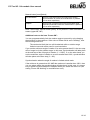
1.2 Information on using the manual
An arrow symbol shows the order of menu commands in sub-menus. For the
function
MP-Channel ` Trigger Scan (MP Strang ` Scan auslösen)
select MP-Channel in the main menu and then Trigger Scan in the sub-menu.
Notes are enclosed in separation lines.
Variant
If a function can be triggered in several ways, variant ways are described in
addition to the recommended way.
4 /47
PC-Tool V3.1 General part User manual
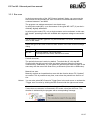
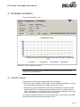
1.3 General structure of the user interface
A
B
D
C
E
User interface of PC-Tool 3.0
The menu bar [A] and the toolbar [B] provide functions that affect the program
as a whole. An explanatory text (tooltip) appears for each icon in the toolbar
when you position the mouse pointer on it.
The MP-Channels and actuators belonging to the project are displayed in the
outline bar [C] in the form of a tree (as in the Explorer). The object to be worked
on is marked here. Depending on the selected object, pop-up menus offer
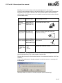
corresponding functions at a click of the right mouse button.
Pop-up menu after clicking the right mouse button
The detail area [D] contains all the detailed information on the marked object.
The values that are displayed and changed in this area are grouped as needed
and distributed over several index cards.
The status bar [E] at the lower margin shows the current status of the connected
device (e.g.: the actuator is carrying out a synchronization or adaptation.)
5 /47
PC-Tool V3.1 General part User manual
Missing or invalid entries are indicated by a flashing exclamation mark. If you
move the mouse pointer to the exclamation mark, an explanatory text (tooltip)
appears.
Inactive commands are displayed in gray letters (or as gray icons) according to
the Windows standard.
Texts in fields with a black font on a gray background cannot be changed. You
can mark the contents with the mouse, however, and copy them into the clipboard with CTRL+C, for example.
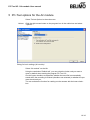
1.4 Modules and actuator types
Multifunctional damper actuators
The following actuator types can be parameterized with the program
PC-Tool Version 3:
Generation
Type
MP-Bus
Sensors
NEW
MP
YES
active, passive, switch
MF
No
(none)
MFT2
YES
active, passive, switch
MFT
YES
active, switch
OLD
The manual is organized according to the application areas for actuators
(modules). Detailed descriptions can be found in the module-specific sections
(e.g. Air Module, Water Module, VAV Module).
6 /47
PC-Tool V3.1 General part User manual
2 Getting started with PC-Tool 3.0
2.1 Connecting the computer with the actuators
Connect the ZIP-RS232-Box to your computer via the serial interface (COM1).
The connection of the actuators to the ZIP box is explained in the Appendix.
If you use a different interface than COM1, you must subsequently adapt the
setting [Ö 3.3.1 Serial interface].
For typical wiring diagrams see Ö 4.4 Typical wiring diagrams
2.2 Starting the program
Click the program icon on your desktop. A start screen appears.
Click Start Belimo PC-Tool (bottom right).
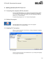
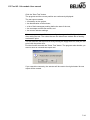
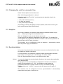
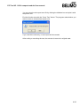
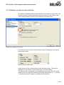
2.3 Adapting PC-Tool options
When you start the program for the first time, a dialog is displayed for adapting
the user-specific settings.
PC-Tool options
Select the desired language in the combobox here. If you change the language,
exit the program and restart it.
7 /47
PC-Tool V3.1 General part User manual
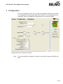
2.4 Creating a new project
To work with the program, you have to create a “project”. The dialog for entering
the project data is displayed. Click the radio button “New project”.
Creating a new project
The project name, company and user ID must be filled in; all other information is
optional.
2.5 Setting up the program
The project and the MP-Channel can be seen in the outline bar [C]. The bus is
scanned every 10 seconds by default.
Outline bar [C]
If no actuators are shown after 10 seconds, you should check whether the ZIPRS232-Box is connected to COMx. Adjust the settings for the serial interface if
necessary [Ö 3.3.1].
8 /47
PC-Tool V3.1 General part User manual
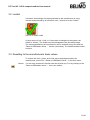
2.6 Displaying actuator parameters
Select the desired actuator in the outline bar [C] by clicking it with the mouse.
The current settings for the actuator are displayed in the detail area [D].
Example of detail area [D] (damper actuator)
2.7 Further actions
Read the descriptions for the following topics in chapter 3 Basic functions:
Bus scan
Setting the bus address
Parameterization of actuators
Read the details for the application areas of the actuators in the descriptions of
the following modules:
Damper actuators (Air module)
VAV controllers
9 /47
PC-Tool V3.1 General part User manual
3 Basic functions
3.1 Program start
After the program is started, a start screen is displayed.
Click Start Belimo PC-Tool.
Determine the project with which you want to work. You can either
open one of the last projects listed,
open an existing project from a file, or
create a new project.
The defined MP-Channel is displayed and opened. A bus scan is started for each
MP-Channel.
If only one actuator is connected, it is automatically selected and displayed.
Variant
If you cancel the project selection, the program will be started without a project.
In this case, only the functions Help, File ` New Project (Hilfe, Datei ` Neues Projekt) and File ` Open Existing Project (Datei ` Bestehendes Projekt öffnen) will
be available.
You can also start the program by opening a project file: In the Explorer, double
click on a file with the extension .bptpj or on a corresponding link to a file.
In a network environment, the program should be installed on your workstation
and started locally. Special authorizations are required to start the program on
network drives.
10 /47
PC-Tool V3.1 General part User manual
3.2 Projects
3.2.1 Project data
All user-specific data of the program are administered in the framework of projects. Each project has a project directory in the file system. The project files are
stored in sub-directories of the project directory.
The storage place of the project files is described in the Appendix.
3.2.2 Creating a new project
Select File ` New Project in the main menu. Enter the new project data in the dialog. The project name, company and user ID must be filled in; all other information is optional. Click OK.
Since only one project can be active at a time, the currently displayed project will
be closed and the new project opened.
Variant
You can also create a new project by clicking the “New Project” icon in the toolbar [B] or clicking the program icon in the outline bar [C] with the right mouse button and then selecting New Project.
3.2.3 Opening a project
Select File ` Open Existing Project (Datei ` Bestehendes Projekt öffnen) in the
main menu. Mark a project from the list in the dialog or open any given project file
(*.bptpj) with Find… (Suchen…). Click OK.
Since only one project can be active at a time, the currently displayed project will
be closed and the selected project opened instead.
Variant
You can also open a project by clicking the “Open Project” icon in the toolbar [B]
or clicking the program icon in the outline bar [C] with the right mouse button and
then selecting Open Project.
3.2.4 Changing project data
Click the project in the outline bar [C] to display the project data. The “Edit” button
(far right) displays a dialog in which you can change the data.
Variant
Click the project in the outline bar [C] with the right mouse button and select
Properties (Eigenschaften).
The project name and path cannot be changed within the program. However, you
can rename the project file (extension .bptpj) using Windows Explorer or
move the entire project folder to another location. Afterwards, open the project
again.
The project folder and project file can have different names – for example for
backing up data. The name of the project file determines the project name.
11 /47
PC-Tool V3.1 General part User manual
3.2.5 Exporting a project
Copy the entire project folder in the Explorer, for example onto a floppy disk.
3.2.6 Copying a project
Copy the entire project folder to another location in the Explorer. Give the project
folder a new name. Give the project file (<project>.bptpj) the same name within
the new project folder.
3.2.7 Deleting a project
Delete the entire project folder in the Explorer. The project to be deleted must not
be currently open in the program.
3.3 MP-Channel
3.3.1 Serial interface
The ZIP level converter is connected to a serial interface (COM). To select the
number of the serial interface used on your computer, click the MP-Channel icon
in the outline bar [C] with the right mouse button and select Channel configuration.
For typical wiring diagrams, see Ö 4.4 Typical wiring diagrams
Now set the serial connection:
If you activate the “Serial connection” field (as shown in the screenshot below),
you can select a serial connection between COM=1 and COM=9 in the pulldown menu.
If you activate the “Other” field, you can enter a serial connection number between 1 and 255 directly in the field (e.g. COM=12 for serial connection 12).
Channel configuration
12 /47
PC-Tool V3.1 General part User manual
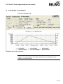
3.3.2 Bus scan
In the bus scan section of the “MP-Channel settings” dialog, you can enter the
time interval for the periodic bus scan in seconds. Permitted values are whole
numbers between 1 and 9999.
The program can address actuators in two basic ways:
In multi-point mode (MP), up to 8 actuators of the types MP / MFT (2) can be individually digitally addressed.
In point-to-point mode (PP), only a single actuator can be activated. In this case,
the “classic” operating modes are available with response voltage at connection
D5.
The actuators of the MF type can only be connected in PP mode, all others either
in PP or MP mode.
Select the type of bus scan in the bus scan section of the “MP-Channel settings”
dialog.
PP Only
Connection of a single actuator in PP mode
MP / PP
First scan address 1 to 8 in MP mode;
if no response in MP mode, switched to PP mode
Periodic bus scan
The periodic bus scan is active by default. To switch this off, click the MPChannel with the right mouse button and select Interrupt Scanning (Scannen
unterbrechen). Afterwards, you can switch the periodic scan back on again in the
same way with the menu item Scan Every xx Seconds (Scan alle xx Sekunden).
Manual bus scan
Manually activate an immediate bus scan with the function button F5 (“Update”)
as needed. This is possible at any time, even when the periodic bus scan is active.
Variant
You can also select MP-Channel ` Trigger Scan in the main menu or activate the
“Trigger scan” function by clicking the MP-Channel with the right mouse button.
If more than one actuator responds to the same MP address during a bus scan or
if more than one actuator is connected in PP mode, a bus jam will occur. This
situation is indicated by the program with a corresponding message.
13 /47
PC-Tool V3.1 General part User manual
3.4 Setting the bus address
Each actuator with an MP-Bus interface (valid for all devices with MP-Bus interface, e.g. I/O modules etc.) can be assigned an address which it will use to communicate on the MP-Bus.
The setting of the bus address can be disabled on certain actuators, e.g. for the
actuator types ...LON and ...ALON (for LONWORKS®).
3.4.1 Series addressing of devices
Click the “Address device” icon in the toolbar [B].
Variant
Click the MP-Channel with the right mouse button and select Address Device
(Teilnehmer adressieren). Or select MP-Channel ` Address User (MP-Strang `
Teilnehmer adressieren) in the main menu.
Series addressing
If you want to use something other than the default order, then select the desired
addresses in the comboboxes on the right.
14 /47
PC-Tool V3.1 General part User manual
Reading in the serial numbers with acknowledgement on the actuator
Press the acknowledge button on the actuator that is to receive the first address.
Depending on the type of actuator, this is the manual button, the L/R switch or
the S2 button. (If the buttons are not accessible, enter the serial numbers directly
as described below.)
Actuator family
Actuator type
Acknowledge function
Actuators
NM24-MFT(2)
without spring AM24-MFT(2)
return
GM24-MFT(2)
Press manual button once!
Actuators with LF24-MFT(2)
spring return AF24-MFT(2)
Move L/R switch back and forth once
(within 4 seconds)!
L
R
Linear actua- NV24-MFT(2)
tors for valves NVF24-MFT(2)
Actuate button S2 (under the housing
cover) once!
S2
NVF24-MFT(2)-E
Actuators of
...MP
the New Gen- ...MF
eration
...ALON
Actuate the "Address” button
The serial number of the actuator is read out after the acknowledgement and written into the input field. The cursor jumps to the next line.
Repeat this process for all actuators that are to be addressed and then click “Set
Address”.
If one of the addresses is already assigned to another actuator, a message will
be displayed:
Message when an address is already assigned (series addressing)
15 /47
PC-Tool V3.1 General part User manual
Click Yes to initially release the address. The actuator that used to occupy the
address is set to PP.
If you select No, the actuator will also be set to the already assigned address,
and a bus jam can occur.
Click Cancel to stop the series addressing at this point. You can now rearrange
the addresses or end the entire process.
3.4.2 Addressing with known serial numbers
Each MP/MFT(2) actuator is delivered with a label containing its individual serial
number. These serial numbers can be used to assign a PP or an MP1 ... MP8
address to the actuator. An additional, removable label with an identical serial
number is supplied with the actuator. If the actuator is installed at a particular position in the system, this additional label can be affixed at the same position in the
system diagram. This records where the actuator with the corresponding serial
number is located in the building. These serial numbers can be used to assign
the MP1 ... MP8 addresses to the actuators.
Therefore you can also fill in the input fields manually before clicking Set Address, for example when the buttons of the actuators are not accessible or you
regularly take the serial numbers from your documents.
3.4.3 Resetting actuator addresses
If you want to reset actuators with MP addressing to PP, click to the right of the
MP-Channel and select “De-address Device” (“Teilnehmer de-adressieren”) in
the pop-up menu.
Selection of the addresses to be reset
Mark the addresses whose actuators are to be de-addressed.
16 /47
PC-Tool V3.1 General part User manual
When the bus scan is set to MP/PP, the de-addressed actuators are no longer
visible in the outline bar [C] as long as there are still actuators with addresses.
If you set several actuators to PP, a bus jam will occur with the bus setting “PP
Only”.
3.4.4 Addressing a single actuator
Select the actuator in the outline bar [C] and click the “Change MP Address” icon
in the toolbar [B].
Setting a new address
Variant
Click on the actuator with the right mouse button and select “Change MP Address” (“MP-Adresse ändern”).
Select the new address in the combobox. If the address is already assigned to
another actuator, a message will be displayed:
Message when an address is already assigned
Click Yes to initially release the address. The actuator that used to occupy the
address is set to PP.
If you select No, the actuator will be set to the already assigned address, and a
bus jam can occur.
17 /47
PC-Tool V3.1 General part User manual
3.5 Selecting a module
All actuators that are active and connected to an MP-Channel are displayed in
the outline bar [C]. Select the desired actuator from this display.
The type of actuator is indicated by the icon:
Icon
Actuator type
Damper actuator
Valve actuator
Window ventilation actuator
Actuator for fire and smoke dampers
VAV (Variable Air Volume) controller actuator
THC24-MP
UST-3 I/O module
Unknown actuator
When an actuator is selected for the first time, the parameters are read out and
displayed in the detail area [D].
In addition, the address for communication on the MP-Channel (MP or PP mode)
and the name of the actuator type are displayed in the outline bar [C].
The complete information for identifying the selected actuator is found in the
header of the detail area [D].
Display of the actuator identification
Note the difference between the current communication mode on the MPChannel and the displayed address. An actuator with the address MP2 can be
activated in PP mode during a bus scan, for example.
18 /47
PC-Tool V3.1 General part User manual
3.6 Actuator parameters
3.6.1 Displaying actuator parameters
The parameters of an actuator are displayed on the Service card in the detail
area [D].
Example of the “Service” card (damper actuator)
The Test, Adaption and Synchronization functions are described for each respective module.
3.6.2 Printing out actuator parameters
The displayed actuator parameters can be printed out. Click the printer icon in the
toolbar [B] or select Print Actuator Parameters (Antriebsparameter drucken) in
the pop-up menu after clicking the actuator in the outline bar [C] with the right
mouse button.
3.6.3 Deleting maintenance/error messages
When an actuator has created and saved maintenance or fault messages, these
are displayed on the Service card.
Message display on the Service card
Use “Reset Messages” to delete the messages stored in the actuator.
19 /47
PC-Tool V3.1 General part User manual
3.7 Configuring an actuator
To change the parameters of an actuator, go to the Configuration card.
Example of the “Configuration” card (damper actuator)
The lower area with the basic settings can be displayed with the “More” (“erweitern...”) button and hidden again with the “Less” (“reduzieren”) button.
When you change a value in an input field, the field turns yellow:
The status image on the right additionally shows whether all the displayed values
match those stored in the actuator:
Display matches actuator
Values have been changed
Status image
Save the changed values in the actuator with the “Set” button underneath the
status image.
You can read out the parameters currently saved in the actuator again with the
“Read” button. Entries for values that you have not previously saved in the actuator will be lost as a result.
20 /47
PC-Tool V3.1 General part User manual
3.7.1 Saving a parameter file
You can store the displayed parameters in a file (with the extension .bptpar) with
“Store to file…” on the “Configuration” card. The suggested name for the file consists of the serial number of the actuator, the current date and the time of day.
Since the content of the file corresponds to the values displayed on the screen,
you can change individual values and save variants in files without loading them
on the actuator.
The file can only be saved when all values on the screen are valid.
3.7.2 Loading a parameter file
The values of a saved parameter file can be read back into the input screen for
the configuration with “Load from file…”.
3.7.3 Copying parameters
Read out the parameters of an actuator that you want to copy and save them in a
file. Change the actuator, load the saved parameters from the file and program
the actuator with the copied values.
21 /47
PC-Tool V3.1 General part User manual
3.8 Parameterizing limited lots
You can parameterize x identical actuators (x depends on the power of the voltage supply) with the function “Parameterize Limited Lots".
To parameterize limited lots, save the parameter set to be programmed in a file.
With one parameter set, you can only program actuators from the same actuator
family (e.g. MFT or NMV), i.e. the parameter set used must match the actuator
family.
Connect the devices according to the following wiring diagram:
Power Supply
AC/DC 24 V
GND 24 V
MP
ZK2-GEN
~
T
= wt
= bl
PP = gn
AC/DC 24 V
Rx/ Tx
Enable
Power
T
RJ11 (4/6)
ZIP-232-KA
PP
Belimo
PC-Tool
ZIP-232-KA
more actuators
(total 8)
...MFT(2)
....A-MP
...MFT(2)
....A-MP
...MFT(2)
....A-MP
...MFT(2)
....A-MP
...MFT(2)
....A-MP
...MFT(2)
....A-MP
Mark the desired MP-Channel and click the “Parameterize Limited Lots” icon.
Variant
Click the MP-Channel with the right mouse button and select Parameterize Small
Series. Or select MP-Channel ` Parameterize Limited Lots in the main menu.
22 /47
PC-Tool V3.1 General part User manual
Dialog for parameterizing limited lots
Select the file with the saved parameters in the dialog.
Position the cursor in the first input field for the serial number. Next, press the acknowledge button on the first actuator to be parameterized. If the buttons are not
accessible, directly enter the serial numbers as described below.
The serial number of the actuator is read out after the acknowledgement and written into the input field. The cursor jumps to the next line.
Repeat the process for all actuators that are to be parameterized and mark the
checkbox if you want to print labels after parameterization (see chapter 3.9 “Printing labels”).
Click Parameterize.
The PC-Tool now asks for the file with the values to be written into the actuators.
The periodic bus scan is stopped for the duration of the parameterization. The actuators are successively set to the address MP1, programmed and finally set to
PP addressing.
When the bus scan is set to MP/PP, the actuators in the outline bar [C] will not be
visible. If the bus setting PP Only is used, a bus jam will result.
If an error occurs during programming, a corresponding text is displayed in the
“State” column.
If the address MP1 is already assigned to an actuator, a message will be displayed:
23 /47
PC-Tool V3.1 General part User manual
Message when the address MP1 is already assigned (limited lot)
Click OK to initially release the address MP1. The actuator that used to be assigned to this address will be set to PP.
Click Cancel to stop the parameterization at this point.
Identification with known serial numbers
Naturally, you can also fill in the input fields manually before you click “Parameterize”, for example when the buttons of the actuators are not accessible or you
regularly take the serial numbers from your documents.
Programming further series
The actuators that have been successfully programmed are deleted from the list.
You can enter further serial numbers in the list and click “Parameterize” again.
24 /47
PC-Tool V3.1 General part User manual
3.9 Printing labels
To identify actuators, you can write self-adhesive labels with the PC-Tool 3.0
program. A special printer may be necessary, depending on the type of label.
3.9.1 Setting up a configuration file
Labels are defined per project. To print labels, set place holders (number in
braces) in the configuration file for the information to be printed.
The structure and storage location of the configuration files are described in the
Appendix.
3.9.2 Printing labels
Select an actuator and click the “Print Label” icon (with an orange background).
Variant
Click an actuator in the outline bar [C] with the right mouse button and select “Label Printing”.
Label printing dialog
25 /47
PC-Tool V3.1 General part User manual
Select a printer and a configuration file.
Enter the number of identical labels that are to be printed for “Number of labels
per actuator”. When parameterizing limited lots, the total number of printed labels
is equal to this value times the number of actuators.
Enter the desired texts {41} – {43} that are to be printed, if necessary. A maximum of 50 characters are available per text field. In text with consecutive numbering, a number is entered instead of the place holder “#”. This number is increased by one for each new actuator.
If labels have already been used from a label sheet, you can specify at what label
position the printing should start (for example 4 when 3 labels have been used
from the first row).
Your entries and the selected printer are preserved from one label printing process to the next (automatic saving). You can empty the input fields with “Reset
Form”.
The texts {41} – {44} must be present in the label configuration file in the form of
place holders; otherwise they will not be printed out.
3.9.3 Printing labels offline
Labels can still be printed even if no actuator is connected. In this case, only the
information from the project data, the texts entered in the dialog and the current
date can be output. The start number is always used instead of the place holder
#.
Click the "Print Label" icon (with gray background).
Variant
Click the project in the outline bar [C] with the right mouse button and select
“Print Label”. Or select Project ` Print Label in the main menu.
For “Number of labels per actuator”, enter the number of identical labels to be
printed. The number with the placeholder “#” is NOT counted up. The further procedure is the same for printing actuator labels.
3.10 Transformation tables
Transformation tables are for converting the sensor value into another physical
quantity, for example from resistance (in ohms) to temperature (in °C) for NTC
resistors. Several frequently used transformation tables are supplied with the
program.
Selecting a transformation table
Select a transformation table with the combobox. The corresponding converted
value is displayed underneath the sensor value.
The measured sensor variable in the table must match the selected sensor type:
volts for active sensors, ohms for sensor resistors, on/off for switches.
26 /47
PC-Tool V3.1 General part User manual
Adapting a transformation table
Click the transformation table icon.
Variant
Click the project in the outline bar [C] with the right mouse button and select
Transformation Table. Or select Project ` Transformation Table in the main
menu.
Dialog for editing transformation tables
Select an available transformation table using the combobox.
The sensor values and the converted values are displayed in the table on the left.
On the right, you see a corresponding diagram with the sensor values on the
horizontal axis and the converted values on the vertical axis. The table values are
linearly interpolated; in other words, the points are connected by straight lines to
calculate intermediate values.
During conversion, the first and last connection lines are extended beyond the
range of entered points (extrapolated) so that even sensor values outside of this
range are valid.
You can adapt each value in the table or add new value pairs in the last line,
which is marked with an asterisk (*). Newly added value pairs are automatically
sorted into the right place.
The following holds true for switches: Off = 0, On = 1.
Save the changes to the transformation table by clicking on the floppy disk icon.
27 /47
PC-Tool V3.1 General part User manual
When you change a transformation table in one project, the changes do not affect corresponding tables in other projects. However, you can return to the original project folder from all projects through the entry <Other...> (<Andere...>) in
the combobox and open the changed table.
Setting up a new transformation table
When the dialog for editing a transformation table is open, you can create a new
table with the "New" icon. Select the physical quantities for the sensor values and
the converted values in the comboboxes above the table. You can also write any
other quantities into the text fields of the comboboxes.
For the sensor values, only volts, ohms and on/off are meaningful input quantities, because only these sensor types are supported.
Enter a description in the text field and add new value pairs in the last line of
each table, which is marked with an asterisk (*). A transformation table must have
at least two lines.
For switches, you can define an on/off inversion table with the assignments
0 Æ 1 and 1 Æ 0.
Save the new transformation table by clicking on the floppy disk icon. The name
that you enter in the “Save file as” (“Datei speichern unter”) dialog will be subsequently offered as a selection in the combobox.
If the name of the new table does not appear in the combobox on the “Simulation” card, open the project again.
The new transformation table is not directly available as a selection in the combobox in other projects. However, you can return to the original project folder
from all projects through the entry <Other...> (<Andere...>) in the combobox and
open the new table.
Deleting a transformation table
When the dialog for editing a transformation table is open, you can use the Delete icon to delete a table that has been selected in the combobox.
If the name of the deleted table still appears on the “Simulation” card in the combobox, open the project again.
28 /47
PC-Tool V3.1 General part User manual
3.11 Displaying recorded trend data
Click the Trend Recall icon.
Variant
Click the project in the outline bar [C] with the right mouse button and select
“Trend Recall”. Or select Project ` Trend Recall in the main menu.
Trend recall
Select a trend file with the combobox.
The name of the file consists of the information
project_devicetype_position_serialno_day_time_trend.bpttnd
Keep the CTRL button pressed and pull the diagram to the left or right with the
mouse to display values for other times.
You can use the copy button to insert the diagram into other documents via the
clipboard.
Printing a trend
Click the Print icon or press the key combination CTRL-P.
Variant
In addition to the Print button, you can open a menu with the “down” key. In addition to printing, this allows you to display a preview or select several files for printing with “Print Multiple” (“Mehrfach Drucken”).
29 /47
PC-Tool V3.1 General part User manual
3.12 PC-Tool options
Select Tools ` PC-Tool Options... in the main menu.
Variant
Click the right mouse button on the program icon in the outline bar [C] and select
“Options…”.
Dialog for basic settings (general)
“Project base path” sets the default directory in the file system, in which the new
project folder will be saved. You can override this information when creating new
projects, however.
When you mark the “Use default” checkbox, new projects will be saved in your
user profile under “My Documents”. With the operating system Microsoft Windows XP (English), this folder is located under
C:\Documents and Settings\<Name>\My Documents.
You can open the folder “My Documents” with the “My Computer” icon.
The language that you select in the combobox will be used the next time that you
start the program.
In addition to “General”, the names of the supported modules (actuator families)
are displayed on the left side. Further information on the module-specific settings
is found in the corresponding sections of this manual.
30 /47
PC-Tool V3.1 General part User manual
3.13 Log file
All activities with the PC-Tool software that influence the data stored in the actuator are recorded in a separate log file for every project. The time of each action is
logged.
Configuring the log file
You can create a separate log file for each week or month of a project (default:
File per week). To change this setting, select Tools ` Options in the main menu.
You can select either ‘File per week’ or ‘File per month’ under ‘General’.
Reading the log file
Click the “Read log file” icon in the toolbar.
Variants
Click the project icon in the outline bar [C] with the right mouse button and select
‘Read log file’. Or select Project ` Read log file in the main menu.
Using the combo box ‘Log file’, you determine the file to read. The contents of the
log file are displayed in a table in the top section (each action starts a new row).
By clicking a column title, you can sort the table according to the selected column. By clicking the same column title again, you reverse the sort direction: ascending (A-Z) or descending (Z-A).
Details
Click a table row to display details of this action in the bottom section.
You can print the text in the detail area (“Print…” button) or copy it to the clipboard (“Copy” button) and then paste it into another document.
31 /47
PC-Tool V3.1 General part User manual
32 /47
PC-Tool V3.1 General part User manual
4 Appendix
4.1 Storage locations of files
4.1.1 Project data
The default project is saved in the “Default project” sub-directory in the installation directory of the program.
The projects are user-specific and are stored as a sub-directory in the user profile
under “My Documents”. For an English-language version of Windows, this is
C:\Documents and Settings\<Name>\My Documents\Belimo\PCTool
This directory contains sub-directories with the project names.
4.1.2 Configuration files
The user-specific settings are stored in the user profile under “Application data”.
For an English-language version of Windows, this is
C:\Documents and Settings\<Name>\Application Data\Belimo\PCTool
This directory can be “hidden” under Windows. If it is not present, the settings will
be queried upon starting.
33 /47
PC-Tool V3.1 General part User manual
4.2 Configuration files for printing labels
4.2.1 Storage location
The filenames have the extension *.bptlb. They are saved in the “label definition" directory for each project. For an English-language version of Windows, this
is
C:\Documents and Settings\<Name>\My Documents\Belimo\PCTool\ <Project>\label definition
4.2.2 Format
The configuration files for label printing are stored in XML format. You can edit
these files with an editor program, for example “Notepad”.
Configuration files for common Avery and Zweckform labels are supplied with the
program.
Example of a configuration file
<?xml version="1.0" encoding="utf-8"?>
<LabelDefinition xmlns:xsd="http://www.w3.org/2001/XMLSchema"
xmlns:xsi="http://www.w3.org/2001/XMLSchema-instance">
<PageSize Height="278" Width="214" />
<PageBorder Top="18" Left="5" />
<LabelSize Height="33" Width="100" />
<LabelBorder Top="5" Left="5" />
<Lines>
<Line Text="" />
<Line Text="{0} / {1}" />
<Line Text="{20}" />
<Line Text="{21}" />
<Line Text="{23}" />
<Line Text="{41} / {42}" />
</Lines>
</LabelDefinition>
34 /47
PC-Tool V3.1 General part User manual
4.2.3 Fields
You can adapt the values for the page layout (values in millimeters) for new label
formats.
PageSize
Page size (height and width)
PageBorder
Border width (top and left) = distance from the top left corner of
the first label to the page border
LabelSize
Size of an individual label
LabelBorder
Label border width (top and left) = distance of the lettering from
the label border
In each line element <Line>, you can insert place holders where certain project
and actuator characteristics will be added during printing.
{0}
Company name (from project data)
{1}
Project name
{10}
Actuator type
{11}
OEM designation
{12}
Position
{13}
Serial number
{14}
MP address
{20}
Control type Y
{21}
Feedback signal U5
{22}
Range of rotation min – mid – max
{23}
Running time
{24}
Direction of rotation (cw /ccw)
{25}
Position when bus failure occurs
{26}
Sensitivity
{27}
Synchronization at
{28}
Torque
{29}
Adapted rotation range
{30}
Calibration value
{31}
Vnom
{32}
Vmax
{34}
Vmin
{36}
Type of control
{37}
Mode
{40}
Printing date
{41}
Text with consecutive numbering
{42}
Freely definable text 1
{43}
Freely definable text 2
{44}
Freely definable text 3
You can define up to 50 lines. The program does not check whether the lines fit
on a label.
35 /47
PC-Tool V3.1 General part User manual
When you define a new configuration file in a project, this configuration will not be
directly available in other projects. However, you can return to the original project
folder from all projects by using the entry <Other...> (<Andere...>) in the combobox, and then use the file.
4.2.4 Example of a label
The following example produces a label with W x H dimensions of 50 x 20 mm.
The example is intended for an endless label printer that prints labels of the size
50 x 20 mm.
The company name, the project name, the actuator type, the type of control signal and the running time are printed on the label.
This data yields the following configuration file and the subsequently displayed
label:
<?xml version="1.0" encoding="utf-8"?>
<LabelDefinition
xmlns:xsd="http://www.w3.org/2001/XMLSchema"
xmlns:xsi="http://www.w3.org/2001/XMLSchema-instance">
<PageSize Height="20" Width="50" />
<PageBorder Top="0" Left="0" />
<LabelSize Height="20" Width="50" />
<LabelBorder Top="5" Left="5" />
<Lines>
<Line Text="{0}"/>
<Line Text="{1}"/>
<Line Text="Typ: {10}"/>
<Line Text="{20} Running time: {23}"/>
</Lines>
</LabelDefinition>
Label:
{0}
Belimo Automation AG
Sample
Type: LM24A-MP
Y: Open/Close Running time: 40s
{20}
{1}
{10}
{23}
36 /47
PC-Tool V3.1 General part User manual
4.3 Troubleshooting and error messages
4.3.1 General
Problem
After the program starts, an MP-Channel is not opened but displayed closed with
the “MP-Channel” icon.
Solution
The MP-Channel cannot be opened, for example because the selected serial
interface is assigned to another application. Check whether a modem or a communication program is using this interface.
4.3.2 Error messages
Error message
Description
Adaption could not be started.
Communication failure on the MP-Channel or faulty actuator
Actuator cannot be acessed.
Communication failure on the MP-Channel or faulty actuator
Response contains too little data.
Conflict between actuator and program. The program library
(belipp.dll) may not be up-to-date.
Response contains too much data.
Conflict between actuator and program. The program library
(belipp.dll) may not be up-to-date.
Command has too few parameters.
Conflict between actuator and program. The program library
(belipp.dll) may not be up-to-date.
Command parameter outside of the
expected range.
Conflict between actuator and program. The program library
(belipp.dll) may not be up-to-date.
Belimo library error code = ….
Internal fault.
The actuator does not recognize the
command … .
Conflict between actuator and program. The program library
(belipp.dll) may not be up-to-date.
The answer of the actuator was faulty.
Conflict between actuator and program. The program library
(belipp.dll) may not be up-to-date.
The PP function of the Belimo library
does not recognize the MP command.
….
Conflict between actuator and program. The program library
(belipp.dll) may not be up-to-date.
This device already has the address …
Re-addressing assigns an already existing address.
A transformation table has at least 2
data points.
A transformation table must have at least 2 lines to be able to
calculate intermediate values.
Wrong actuator connected!
This fault occurs when actuators are changed during parameterization. Read out the parameters again.
Wrong MP-Channel: "...".
The MP-Channel has changed.
Faulty handle
Internal fault.
No response (possible bus jam).
Communication problem on the MP-Channel or faulty actuator.
No response from actuator.
Communication failure on the MP-Channel or faulty actuator.
Could not write data to the actuator!
Communication failure on the MP-Channel or faulty actuator.
37 /47
PC-Tool V3.1 General part User manual
Error message
Description
Could not copy sample project. Default
project directory '...' does not exist!
Please re-install application.
When a new project is created, configuration files and subdirectories are normally copied from the default project in the
installation directory of PC-Tool 3.0. The default project has
probably been accidentally deleted, moved or renamed.
Could not find PC-Tool V2.1. Do you
want to search for it?
Affects VAV actuators. The old version of the program could
not be found at the location specified in the PC-Tool options.
MP command … failed.
Conflict between actuator and program. The program library
(belipp.dll) may not be up-to-date. MP command could be
password-protected.
MP-Channel was closed.
The MP-Channel was closed during an asynchronously
running function.
Not all data could be written.
Communication problem during writing of the parameter data,
possibly due to bus jam. Check the connection and addressing
of the actuators. An MP command is password-protected or
the actuator does not recognize the command.
Not all data could be read out.
Communication problem while the parameter data was read,
possibly due to bus jam. Check the connection and addressing
of the actuators.
Not all entries are valid! Cannot write
data.
One or more input values on the “Configuration” card is not
valid. Look for a flashing exclamation mark. If you move the
mouse pointer to the exclamation mark, an explanatory text
(tooltip) with the valid range of values will usually appear.
OEM or BELIMO password necessary.
Parameters on the actuator can be protected with a password
against changes. A password is necessary to overwrite them.
Problems opening the MP-Channel
"...".
Error at the interface. Check the communication parameters
and the cabling.
Transmission from ... to ... yielded the
error code ....
Conflict between actuator and program. The program library
(belipp.dll) may not be up-to-date.
Serial number is incorrectly formatted!
You have made a typing error while manually entering the
serial number. Check the notation of the serial number.
Error messages could not be deleted.
Communication failure on the MP-Channel or faulty actuator.
Synchronization could not be started.
Communication failure on the MP-Channel or faulty actuator.
Test run could not be started.
Communication failure on the MP-Channel or faulty actuator.
Re-addressing check has failed.
The serial number is read before and after an actuator is readdressed. These two numbers do not match. Another
actuator probably answers to the programmed address.
Unknown MP-Channel "...".
The MP-Channel could not be identified.
Invalid or faulty parameter file '...'
The contents of the file could not be correctly interpreted. The
format may no longer be valid. If possible, read out the
parameters again and save them in a new file.
Unspecific error of the Belimo library.
Internal fault.
38 /47
PC-Tool V3.1 General part User manual
4.4 Typical wiring diagrams
4.5 Overview table
Typical wiring diagrams with ZIP-232-KA (ZIP cable)
Actuator types
Typical wiring diagram
Cable
….-MF
…..-MP
...MFT(2)
Typical wiring diagram 1
ZK1-GEN
x
x
ZK2-GEN
x
x
x
ZK2-GEN
x
x
ZK4-GEN
x
x
…LON
...ALON
x
Connection via diagnostic
socket with ZIP-232-KA;
actuator is integrated in
system
Typical wiring diagram 2
x
x
Connection via connection
cable with ZIP-232-KA;
actuator is integrated in
system
Typical wiring diagram 3
Connection to MP-Bus via
connection cable with ZIP232-KA
Typical wiring diagram 4
Connection to
MP-Bus via
MP gateway with
ZIP-232-KA
39 /47
PC-Tool V3.1 General part User manual
Typical wiring diagrams with ZIP-RS232
Actuator types
Typical wiring diagram
Cable
Typical wiring diagram 5
ZK3-GEN
….-MF
...-MP
…MFT(2)
x
x
x
x
x
x
x
x
…LON
….ALON
x
Connection via diagnostic
socket with ZIP-RS232;
actuator is integrated in
system
Typical wiring diagram 6
Connection via connection
cable with ZIP-RS232;
actuator is integrated in
system
Typical wiring diagram 7
Connection via connection
cable with ZIP-RS232;
parameterization outside
of system
Typical wiring diagram 8
x
x
x
x
Connection via connection
cable with ZIP-RS232;
actuator is integrated in
system
Typical wiring diagram 9
Connection via connection
cable with ZIP-RS232;
parameterization outside
of system
Typical wiring diagram 10
ZKS-MP
x
x
x
Connection to
MP-Bus via
MP gateway with
ZIP-RS232
40 /47
PC-Tool V3.1 General part User manual
4.5.1 Typical wiring diagrams
Typical wiring diagram 1
RJ11 (4/6)
~T
+
Rx/ Tx
Enable
Pow er
ZIP-232-KA
_
Belimo
PC-Tool
AC 24 V
DC 24 V
ZIP-232-KA
ZK1-GEN
Typical wiring diagram 2
~ T
AC 24 V
+ DC 24 V
ZK2-GEN
= wt
= bl
PP = gn
~
T
5
Belimo
PC-Tool
Rx/ Tx
Enable
Pow er
RJ11 (4/6)
ZIP-232-KA
PP
1 2
~
T
_
ZIP-232-KA
~ T
_
+
...MFT (2)
...A-M F
...A-M P
...LON (US)
...ALON
41 /47
PC-Tool V3.1 General part User manual
Typical wiring diagram 3
MP-Master
DDC
Controller
UK...Gateway
GND 24 V MP
ZK2-GEN
~
T
= wt
= bl
PP = gn
AC/DC 24 V
Rx/ Tx
Enable
Power
T
RJ11 (4/6)
ZIP-232-KA
PP
Belimo
PC-Tool
ZIP-232-KA
...MFT(2)
....A-MP
...MFT(2)
....A-MP
...MFT(2)
....A-MP
...MFT(2)
....A-MP
...MFT(2)
....A-MP
...MFT(2)
....A-MP
...MFT(2)
....A-MP
...MFT(2)
....A-MP
42 /47
PC-Tool V3.1 General part User manual
Typical wiring diagram 4
AC 24 V
DC 24 V
T
!
_
~
Connect via
a safety
transformer
+
UK24LON/EIB
MFT-H
R J11 (4/6)
LonTalk
a b
B elim o
P C -To ol
Power
0V 24V n.c.
MP-Com.
0V 24V Y U/MP
Rx/ Tx
En a b le
Po w er
Z IP-2 3 2-KA
ZIP-232-KA
ZK4-GEN
U5
MP
T
~
+
...MFT(2)
....A-MP
_
1
2
_
5
3
U5
+
MP
...MFT(2)
....A-MP
T
_
5
3
2
~
2
U5
+
MP
...MFT(2)
....A-MP
1
5
3
U5
MP
+
...MFT(2)
....A-MP
1
2
_
1
2
T
T
~
T
~
+
...MFT(2)
....A-MP
1
5
3
~
5
U5
MP
_
T
_
3
2
~
2
U5
+
MP
...MFT(2)
....A-MP
1
T
1
5
~
_
3
T
2
~
1
5
3
U5
+
MP
...MFT(2)
....A-MP
_
5
3
U5
MP
+
...MFT(2)
....A-MP
43 /47
PC-Tool V3.1 General part User manual
R S232
Typical wiring diagram 5
Belimo
PC-Tool
A C 230 V
D-Sub
24V
GN D
Z N 2 3 0 -2 4
A C 230/ 24 V
RS-232
K a b elead
l R S -2 3 2
o l fe m a le /fe m a le
9-pol9 -p
female/female
1 :1 dconnection
u rc h v e rb u n d e n
1:1 thro'
(
im
L
ie
fe ru m
fa n g Z IP -R S 2 3 2 )
(included with
ZIP-RS232)
1
5
2
-
Supply
T
2
+
~
1
2
D-Sub
MP-Bus
E
U5
PP N
T
T
OFF
U
PP
~
A c tu a to r
ON
R S 232
ZIP-RS232
1
1
K a be l ZK 3- GE N
2
~
T
_
+
AC 24 V
DC 24 V
!
Connect via
a safety
transformer
RS232
Typical wiring diagram 6
Belimo
PC-Tool
D-Sub
RS-232 lead
9-pol female/female
1:1 thro' connection
(included with ZIP-RS232)
1
2
T
~
_
+
3
T
OFF
~
Actuator
ON
U
PP
1
2
5
RS232
ZIP-RS232
D-Sub
5
U5
MP
.......MFT(2)
.......MF
.......MP
44 /47
PC-Tool V3.1 General part User manual
ZN230-24
AC 230/ 24 V
RS232
Typical wiring diagram 7
Belimo
PC-Tool
AC 230 V
D-Sub
RS-232 lead
9-pol female/female
1:1 thro' connection
(included with ZIP-RS232)
ZIP-RS232
3
D-Sub
5
5
-
T
~
.....MFT(2)
U5
MP .....A-MF
.....A-MP
+
RS232
2
Supply
+
~
T
_
2
1
U
PP
MP-Bus
U5
PP
EN
T
1
T
OFF
~
Actuator
ON
AC 24 V
~T
_ + DC 24 V
!
Connect via
a safety
transformer
RS232
Typical wiring diagram 8
Belimo
PC-Tool
D-Sub
LONWORKS®
RS-232 lead
9-pol female/female
1:1 thro' connection
(included with ZIP-RS232)
1
2
T
~
_
+
5
T
OFF
*
~
Actuator
ON
1
2
U
PP
RS232
ZIP-RS232
D-Sub
5
* .... LON (US)
...... LON (US)
...... ALON
45 /47
PC-Tool V3.1 General part User manual
ZN230-24
AC 230/ 24 V
RS232
Typical wiring diagram 9
Belimo
PC-Tool
AC 230 V
D-Sub
RS-232 lead
9-pol female/female
1:1 thro' connection
(included with ZIP-RS232)
ZIP-RS232
T
T
~
_
+
Supply
+
MP-Bus
U5
PP
EN
5
MFT
2
D-Sub
5
-
1
RS232
2
~
1
U
PP
T
OFF
T
LONWORKS®
~
Actuator
ON
...... LON (US)
...... ALON
46 /47
PC-Tool V3.1 General part User manual
AC 230 V
D-Sub
!
AC 24 V
DC 24 V
T
Belimo
PC-Tool
Connect via
a safety
transformer
_
~
RS232
Typical wiring diagram 10
+
ZN230-24
AC 230/ 24 V
RS-232 lead
9-pol female/female
1:1 thro' connection
(included with ZIP-RS232)
UK24LON /EIB
MFT-H
ZIP-RS232
RS232
Power
0V 24V n.c.
MP-Com.
0V 24V Y U/MP
D-Sub
5
-
Supply
+
T
2
LonTalk
a b
2
~
1
U
PP
MP-Bus
U5
PP
EN
ZKS-MP
T
T
OFF
~
Actuator
ON
1
T
~
T
~
T
~
+
...MFT(2)
....A-MP
_
_
5
1
2
T
2
2
~
1
U5
MP
1
U5
MP
+
...MFT(2)
....A-MP
3
U5
MP
+
...MFT(2)
....A-MP
_
5
3
1
2
U5
MP
_
5
1
2
T
5
3
5
3
~
T
_
~
2
2
_
+
...MFT(2)
....A-MP
1
1
U5
MP
T
_
5
3
~
2
T
1
2
~
1
+
...MFT(2)
....A-MP
3
U5
MP
+
...MFT(2)
....A-MP
_
5
3
U5
MP
+
...MFT(2)
....A-MP
5
3
U5
MP
+
...MFT(2)
....A-MP
47 /47
PC-Tool V3.1 Air module User manual
PC-Tool V3.0 Air module
for damper actuators
User manual
English
1 /16
PC-Tool V3.1 Air module User manual
Table of contents
1
Introduction........................................................................................................................ 3
2
Service............................................................................................................................... 4
2.1 Displaying settings .................................................................................................... 4
2.2 Adaption .................................................................................................................... 5
2.3 Synchronization......................................................................................................... 6
2.4 Function test.............................................................................................................. 6
3
Configuration ..................................................................................................................... 8
4
Controller simulation........................................................................................................ 13
4.1 Actuator control ....................................................................................................... 13
4.2 Reading out sensors and switches ......................................................................... 14
4.3 Trend recording....................................................................................................... 15
5
PC-Tool options for the Air module ................................................................................. 16
2 /16
PC-Tool V3.1 Air module User manual
1 Introduction
The "Air module" user manual describes the detail area [D] of the Air module.
The documentation is divided according to the three index cards "Service", "Configuration" and "Simulation".
3 /16
PC-Tool V3.1 Air module User manual
2 Service
2.1 Displaying settings
The Service card gives an overview of the current settings of the actuator.
Service card for damper actuators
4 /16
PC-Tool V3.1 Air module User manual
Meaning of the settings
Control function Y
Type of control
Sensitivity
Response sensitivity and reversal hysteresis of the
control function
Feedback U5
Type of feedback signal
Nominal range
Range of rotation within the mechanical limits
Running time
Time needed to pass through the rotation range
Angle of rotation
Programmed rotation range: Min / Mid / Max
Direction of rotation
Clockwise (cw) / counterclockwise (ccw)
Synchronisation at
Stop position 0 % or 100 %
Torque
In percent of the maximum torque
Bus fail position
Behavior when communication fails
Power ON
Behavior when the system is switched on
Manual button [once]
Function when pressed once
Manual button [twice]
Function when pressed twice
(not present in “New Generation” actuators)
Firmware
Software version on the actuator
Config table ID
Identification of the configuration table
Operating time
Number of hours during which the actuator was
connected to the power supply
Active time
Number of hours during which the actuator was mechanically in motion and connected to the power
supply
Stop & Go ratio
Ratio of active time/operating time in percent. A high
Stop & Go ratio indicates an unstable control
2.2 Adaption
In the case of adaption, the actuator determines the rotation range 0 % … 100 %
by moving to the mechanical limits.
Click the “Adaption” button on the Service card.
Variant
You can also trigger the adaption directly on the actuator. The buttons necessary
for this can be programmed. For example, “Manual button [twice]” can be assigned the adaption function.
The progress of the adaption is displayed in the status line. The actuator first
moves against the programmed direction of rotation to the zero stop and then to
the end stop at the full angle of rotation.
Next, the absolute angles of rotation for a programmatically limited rotation range
(minimum, mid-position, and maximum), the feedback signal U5, and the running
time are recalculated and displayed.
5 /16
PC-Tool V3.1 Air module User manual
2.3 Synchronization
In the case of synchronization, the actuator moves to a mechanical limit in order
to determine the absolute angle of rotation.
For each actuator, it is possible to program whether synchronization will take
place at the zero stop (0%) or at the full angle of rotation (100%).
Click the “Synchronization” button on the Service card.
Variant
You can also trigger the synchronization directly on the actuator. The necessary
buttons for this can be programmed. For example, “Manual button [once]” can be
assigned the synchronization function.
The progress of the synchronization is displayed in the status line. With the setting "Synchronization at: Y=0%”, the actuator moves against the programmed direction of rotation to the zero stop, and with the setting “Synchronization at:
Y=100%” to the end stop at the full angle of rotation.
2.4 Function test
The function test checks for complete opening and closing.
Click the “Test” button on the Service card. The standard display is covered by
the test window.
Display of test progress and test report
6 /16
PC-Tool V3.1 Air module User manual
Click the “Start Test” button.
The progress and the current position are continuously displayed.
The test report contains
information on the project,
the identification of the actuator,
a list of fault messages pending before the start of the test,
the test steps and the test results, and
the current actuator settings.
If the test reports an invalid actuator configuration, go to the “Configuration” card
after ending the test. The values that are not allowed are marked with a flashing
exclamation point.
You can save the test report as a file by clicking the floppy disk icon, and you can
print it with the printer icon.
End the function test with the "Close Test" button. The program asks whether you
want to save an unsaved test report now.
If you cancel the test early, the actuator will be reset to its original state. No test
report will be created.
7 /16
PC-Tool V3.1 Air module User manual
3 Configuration
On the “Configuration” card, you can read out parameter values from the actuator, change them and save them back to the actuator. The valid ranges for the
parameter values are displayed in parentheses next to the input fields.
Configuration card for damper actuators
Note:
The set running time is always in relation to the rotation range set with Min and
Max.
8 /16
PC-Tool V3.1 Air module User manual
Actuator number
Designation
16 characters of any text
Position
16 characters of any text
Control signal Y
3-point
AC voltage, positions: Open / neutral / closed
Open / closed
DC or AC voltage, 2-point
DC 0–10 V
(DC voltage)
Fixed operating range DC 0–10 V
DC 2–10 V modulating
(DC voltage)
Fixed operating range DC 2–10 V
DC variable
Start (Y=0%) 0.5 ... 30 V
Stop (Y=100%) 2.5 ... 32 V
Range between start and stop at least 2 V
PWM 0.02–5 s
Duration of the control pulse (pulse width modulation),
fixed operating range
PWM 0.1–25.5 s
Duration of the control pulse, fixed operating range
PWM 0.59–2.93 s
Duration of the control pulse, fixed operating range
PW M 0.02–5 s
Duration of the control pulse, fixed operating range
PWM variable
Start (Y=0%) minimum 0.02 seconds
Stop (Y=100%) maximum 50 seconds
When this function is selected, the actuator is parameterized as a VAV actuator and can therefore be controlled
by the VAV controllers VR.. .
VAV 4 +/- 6V
Note:
When VAV (6 ± 4 V) is selected, the values for minimum, maximum, intermediate value, running time and
angle of rotation are reset to the default values.
Feedback U5 (only active when the actuator address is set to PP)
DC 2 -10V
DC voltage measurement signal, fixed range
DC 0.5 -10V
DC voltage measurement signal, fixed range
DC variable
DC voltage measurement signal
Start 0.5...8.0 V / Stop 2.5 ... 10.0 V
Range between start and stop at least 2 V
...
Certain actuators can define further feedbacks, which
you cannot change, however.
9 /16
PC-Tool V3.1 Air module User manual
U5 scaling (only with “New Generation” actuator, MF or MP types)
Start
Angle of rotation in percent, corresponds to the start
value of the feedback signal
Stop
Angle of rotation in percent, corresponds to the stop
value of the feedback signal
Angle of rotation
Min
Programmatic lower limit of the rotation range
Mid
Mid-position of the rotation range
Max
Programmatic upper limit of the rotation range
Examples of settings for control signal Y / feedback U5
Control signal Y:
Feedback U5 :
3...8 V Min: 30%, Max : 70%
2...7 V Start: 20%, Stop: 90%
Position
Open 100%
50%
Y/U5
[V]
Closed 0%
0
5
10
Running time
In seconds
Time needed to pass through the rotation range limited by
Min and Max (the valid range of values depends on the
actuator type and the rotation range)
10 /16
PC-Tool V3.1 Air module User manual
Direction of rotation
cw
Clockwise
ccw
Counterclockwise
Bus fail position
Last value
Position according to control signal Y
Open
Move to full angle of rotation (100%)
Close
Move to zero stop
Fast close
Close with maximum speed
Sensitivity
Sensitivity
Actuators without
spring-return:
Actuators with Actuators of the
spring return: New Generation:
NM24-MFT(2)
AM24-MFT(2)
GM24-MFT(2)
LF24-MFT(2)
AF24-MFT(2)
..MF
..MP
..LON
- Response sensitivity
1° angle of rotation
1° angle of
rotation
1%
@ operating range
- Reversal hysteresis
2.5° angle of rotation
2.5° angle of
rotation
2.5%
@ operating range
- Response sensitivity: 2° angle of rotation
2° angle of
rotation
2%
@ operating range
- Reversal hysteresis
5° angle of
rotation
5%
@ operating range
Normal
Damped
5° angle of rotation
Synchronization at
Y = 0%
Moves to the mechanical limit at zero stop (depending on
direction of rotation)
Y = 100%
Moves to the mechanical limit at full angle of rotation (depending on direction of rotation)
Torque
25% ... 100%
Can be set in increments of 25%.100% corresponds to the
maximum torque for the actuator type (see nameplate)
Power ON
Synchronization
Moves to a mechanical limit (according to the setting
“Synchronization at”)
Adaption
Moves to both mechanical limits and recalculates angledependent parameters
Nothing
--
11 /16
PC-Tool V3.1 Air module User manual
Manual button [once]/[twice]
Synchronization
Moves to a mechanical limit (according to the setting
“Synchronization at”) when the manual button is pressed
once or twice respectively
Adaption
Moves to both mechanical limits and recalculates angledependent parameters when the manual button is pressed
once or twice respectively
Note: The function “Manual button [twice]” is not present in “New Generation” actuators (types MF, MP)
Additional note on the item “Power ON”:
You can programmatically limit the rotation range at one end by only changing
the minimum or the maximum. If the value of Power ON is set to "Nothing", then
the following holds true:
The mechanical limit that can still be attained within a rotation range
limited at one end will be used for synchronization.
If you set the minimum angle of rotation to a value greater than 0%, the zero stop
will no longer be in the rotation range. In this case, synchronization will take place
at the end stop of the full angle of rotation (Y = 100%). If, on the other hand, you
set the maximum angle of rotation to a value smaller than 100%, synchronization
will take place at the zero stop (Y = 0%).
Synchronization when the angle of rotation is limited at both ends
If the minimum is greater than 0% AND the maximum is smaller than 100%, then
you can select where the synchronization will take place. In this case, it is necessary to perform synchronization or adaption when you switch the device on (the
setting “Power ON: Nothing” is considered an error).
12 /16
PC-Tool V3.1 Air module User manual
4 Controller simulation
Go to the “Simulation” card.
Simulation card for damper actuators
The controller simulation is not possible while the actuator is performing an
adaption or synchronization.
4.1 Actuator control
Select the type of set point definition with the radio buttons.
Set point Y (only available in PP mode): Control signal at connection Y according to selected control type (DC, PWM, open/close, 3-point).
Set point Tool (not available with control type open/close or 3-point): The set
point is entered in % of the programmed rotation range. 0% is the minimum,
100% the maximum. The input values are converted and displayed in the units
of the corresponding control signal (volts or seconds).
The control is switched off when you click “Motor stop”. This function is not available with the control types open/close and 3-point.
13 /16
PC-Tool V3.1 Air module User manual
Measurement values
During the simulation, the current angle of rotation is displayed in % of the absolute (mechanically limited) rotation range and, converted according to the scale
setting, as a feedback voltage in volts.
4.2 Reading out sensors and switches
The values of sensors and switches can be read out in MP mode. This function,
however, must be activated in advance in the PC-Tool options under “Air module”. Select Tools ` Options in the main menu.
Settings for reading out sensors
On the Service card, a section with the sensor values is displayed to the right of
the actuator control.
Sensor display in MP mode
Select the type of the connected sensor with the radio buttons. The value is either
displayed in volts (active), ohms (passive) or as on/off (switch).
The transformation table allows you to additionally convert the raw value of the
sensor into the corresponding measuring quantity (temperature etc…). (See the
“Transformation table” chapter in the General User Manual)
14 /16
PC-Tool V3.1 Air module User manual
4.3 Trend recording
During simulation, the time progress of the set points and actual values can be
displayed in a plot. The values are saved in a trend file and can be displayed
again at a later time. Furthermore, you can add any comment texts you would
like.
In the PC-Tool options for the Air module, you determine whether the trend file is
automatically saved when the recording is finished (checkbox not selected) or
whether the program should ask you.
Click the “Trend” button during simulation. The display changes to a “flat” button.
The recording stops when you click again.
The Trend View radio buttons allow you to set whether the display is given in
percent of the full rotation range (%) or in volts (V).
The position is queried every second by default. You can change the query interval in an input field. The permitted values are 0 to 9999 seconds, whereby the
value 0 means “no waiting time" (query as quickly as possible).
Trend plot
The Comment button allows you to enter a text at a defined time and the text is
then saved in the trend file.
If you want to record a trend for more than one hour (long-term trend), enter a
value of at least 2 seconds for the interval. If the interval is shorter, too many data
points will result and the time for correcting the curve between the queries can
become too short.
15 /16
PC-Tool V3.1 Air module User manual
5 PC-Tool options for the Air module
Select Tools ` Options in the main menu.
Variant
Click the right mouse button on the program icon in the outline bar and select
“Options”.
Dialog for basic settings (Air module)
Select “Air module” on the left.
Using the combobox “Default tab”, you can select the index card you want to
open by default when starting the program PC-Tool 3.0.
Use the upper checkbox to determine whether the trend file is automatically
saved when the recording is finished (checkbox not selected) or whether the program should ask you.
You can activate the function for reading out the sensors with the lower checkbox.
16 /16
PC-Tool V3.1 VAV compact module User manual
PC-Tool V3.1 VAV compact module
for VAV controllers
User manual
English
1 /20
PC-Tool V3.1 VAV compact module User manual
Table of contents
1
Introduction........................................................................................................................ 3
2
Service............................................................................................................................... 4
2.1 Displaying settings .................................................................................................... 4
2.2 Changing the units for volumetric flow ...................................................................... 6
2.3 Adaption .................................................................................................................... 6
2.4 Synchronization......................................................................................................... 6
2.5 Function test.............................................................................................................. 7
3
Configuration ..................................................................................................................... 9
3.1 Settings ................................................................................................................... 10
3.2 Lockbit..................................................................................................................... 13
3.3 Resetting to the manufacturer's basic values.......................................................... 13
4
Controller simulation........................................................................................................ 14
4.1 Actuator control ....................................................................................................... 15
4.2 Test ......................................................................................................................... 15
4.2.1 Test scripts................................................................................................. 16
4.3 Reading out sensors and switches ......................................................................... 17
4.4 Recording a trend.................................................................................................... 18
5
PC-Tool options for VAV module..................................................................................... 20
2 /20
PC-Tool V3.1 VAV compact module User manual
1 Introduction
The “VAV module” user manual describes the detail area [D] of the VAVCompact controller module. The documentation is divided according to the three
tabs “Service”, “Configuration”, and “Simulation”.
Note
For functions and wiring, refer to the product information for VAV-Compact
LMV-D2-MP, NMV-D2-MP, and SMV-D2-MP.
3 /20
PC-Tool V3.1 VAV compact module User manual
2 Service
2.1 Displaying settings
The Service tab gives an overview of the current settings of the VAV-Compact
controller.
Service tab for VAV controllers
The General Part of this manual describes how to print out controller parameters
[chapter 3.6.2.] and delete maintenance or error messages [chapter 3.6.3].
4 /20
PC-Tool V3.1 VAV compact module User manual
Meaning of the settings
Control type
VAV-CAV (variable air volume control) or open loop
operation (operation with an external VAV controller,
actuator and sensor functions)
Control signal Y
Type of control
Sensitivity
Response sensitivity and reversal hysteresis of the control
signal (“open loop” control type only)
Feedback U5
Type of feedback signal (conventional operation)
Nominal range
Rotation range within the mechanical limits
Calibration value
Unit-specific parameter, set by the manufacturer
Volumetric flow setting
Operating volumetric flow settings: V'max / V'min / V'mid
Direction of rotation
Clockwise (cw) / counterclockwise (ccw) opening damper
Synchronization at
Stop position 0% or 100%
Torque
In percent of the maximum torque
Bus fail position
Behavior when communication fails
Power ON
Behavior when the system is switched on or in the event of
a power failure
Manual button [once]
Function when the gear release button is pressed
CAV feature
Override steps: standard or compatible with NMV-D2M
Firmware
Software version of the VAV-Compact
Config table ID
Identification of the VAV-Compact configuration table
Operating time
Number of hours for which the actuator was connected to
the power supply
Active time
Number of hours for which the actuator was mechanically
in motion and connected to the power supply
Stop & go ratio
Ratio of active time/operating time in percent. A high stop
& go ratio indicates unstable control
5 /20
PC-Tool V3.1 VAV compact module User manual
2.2 Changing the units for volumetric flow
Select Tools ` Options in the main menu.
Click “VAV-Compact Module” on the left.
Using the combobox “Flow Unit”, you determine the physical units for the
volumetric flow:
m³/h (cubic meters per hour)
l/s (liters per second)
cfm (cubic feet per minute)
This setting is valid for all displays, printouts, labels, and entries in the log file
[refer to the General Part of this manual].
2.3 Adaption
In the case of adaption, the actuator determines the available rotation range
(0% … 100%) by moving to the mechanical limits.
Click the “Adaption” button on the Service tab to start.
The progress of the adaption is displayed in the status line. The actuator first
moves against the programmed direction of rotation to the zero stop and then to
the end stop at the full angle of rotation.
The actuators can be configured so that an adaption is automatically started
when the power supply is switched on.
2.4 Synchronization
In the case of synchronization, the actuator moves to a mechanical limit in order
to calibrate the position calculation.
For each actuator, it is possible to program whether synchronization will take
place at the zero stop (0%) or at the full angle of rotation (100%).
Click the “Synchronization” button on the Service tab to start.
Variant
You can also trigger the synchronization directly on the actuator by pressing the
gear release button.
The progress of the synchronization is displayed in the status line. With the
setting “Synchronization at: Y = 0%”, the actuator moves against the
programmed direction of rotation to the zero stop, and with the setting
“Synchronization at: Y=100%” it moves to the end stop at the full angle of
rotation.
The actuators can be configured so that a synchronization is automatically
started when the system is switched on.
6 /20
PC-Tool V3.1 VAV compact module User manual
2.5 Function test
The function test checks for complete opening and closing of the damper.
Click the “Test” button on the Service tab. The standard display is covered by the
test window.
Display of test progress and test report
Click the “Start Test” button.
The progress and the current position are continuously displayed.
The test report contains
information on the project,
the identification of the VAV-Compact controller,
a list of error messages pending before the start of the test,
the test steps and the test results, and
the current controller settings.
If the test reports an invalid controller configuration, go to the “Configuration” tab
after it has finished. The values that are not allowed are marked with a flashing
exclamation point.
7 /20
PC-Tool V3.1 VAV compact module User manual
You can store the test report as a file by clicking the diskette icon and print it with
the printer icon.
End the function test with the “Close Test” button. The program asks whether you
want to store an unstored test report now.
If you cancel the test early, no test report will be created.
After ending or canceling the test, the actuator is reset to its original state.
8 /20
PC-Tool V3.1 VAV compact module User manual
3 Configuration
On the “Configuration” tab, you can read out parameter values from the VAVCompact controller, change them and store them in a text file. The valid ranges
for the parameter values are displayed underneath the input fields.
Configuration tab for VAV controllers
The enlarged input fields in the bottom part of the screen are visible if you click
on “Enlarge”.
9 /20
PC-Tool V3.1 VAV compact module User manual
3.1 Settings
Controller ID
Designation
16 characters of any text
Position
16 characters of any text
Volumetric flow, nominal
V'nom
Nominal volumetric flow (set by the manufacturer of the
VAV unit)
Volumetric flow range for “VAV-CAV” control type
V'min
Lower limit of the operating volumetric flow setting
V'max
Upper limit of the operating volumetric flow setting
V'mid
CAV step between V'min and V'max
Shut-off operation
Sets V'min to a fixed value of 0 m³/h
(shut-off operation – damper closed)
You can change the physical units for the volumetric flow by selecting Tools `
Options in the main menu [see chapter 2.2.].
The options also allow you to specify whether the volumetric flow for V'min and
V'max can be entered in percent.
Control type
VAV-CAV
Constant (CAV) or variable (VAV) air volume control
Open loop
Operation with an external VAV controller (actuator and
sensor functions)
Mode (control signal Y / feedback U5)
0 ... 10 V
Sets control signal Y = 0 … 10 V,
feedback U5 = volumetric flow, 0 … 10 V
2 ... 10 V
Sets control signal Y = 2 … 10 V,
feedback U5 = volumetric flow, 2 … 10 V
Other
The control signal Y and the feedback U5 are separately
defined (see below)
Control signal Y
0 … 10 V
Fixed operating range 0 … 10 V
2 … 10 V
Fixed operating range 2 … 10 V
Variable
Start (Y=0%) 0 ... 8 V
Stop (Y=100%) 4 ... 32 V
Range between start and stop at least 2 V
Feedback U5 (only active when the actuator address is set to PP)
10 /20
PC-Tool V3.1 VAV compact module User manual
Damper position
0 … 10 V
Feedback, damper position 0 … 10 V
Damper position
2 … 10 V
Feedback, damper position 2 … 10 V
Variable damper
position
Feedback, damper position
Start 0 ... 8.0 V / Stop 2 ... 10.0 V
Range between start and stop at least 2 V
Volumetric flow
0 … 10 V
Feedback, volumetric flow
0 … 100% V'nom = 0 … 10 V
Volumetric flow
2 … 10 V
Feedback, volumetric flow
0 … 100% V'nom = 2 … 10 V
Variable volumetric
flow
Feedback, volumetric flow 0 … 100% V'nom
Start 0 ... 8.0 V / Stop 2 ... 10.0 V
Range between start and stop at least 2 V
Direction of rotation
cw
Clockwise opening damper
ccw
Counterclockwise opening damper
Angle of rotation
Adapted
Rotation range determined by the mechanical limits
Programmed to
Rotation range 30° ... 95°
Bus fail position
Last value
Volumetric flow is determined by the last set point
received from the MP master
Open
Move to full angle of rotation (100%)
Close
Move to zero stop
Min / V'min
V'min volume
Max / V'max
V'max volume
Sensitivity (“open loop” control type only)
Normal
Normal response sensitivity and reversal hysteresis
(values depend on actuator type)
Damped
Reduced response sensitivity and high reversal
hysteresis (values depend on actuator type)
Synchronization at
Y=0%
Moves to the mechanical limit at zero stop (depending on
direction of rotation)
Y=100%
Moves to the mechanical limit at full angle of rotation
(depending on direction of rotation)
Torque
11 /20
PC-Tool V3.1 VAV compact module User manual
25% ... 100%
Can be set in increments of 25%. 100% corresponds to
the maximum torque for the actuator type (see nameplate)
CAV feature
Standard
NVD-D2M compatible
Override steps:
•
Damper closed
•
V'min
•
V'max
•
Damper open
The CAV steps correspond to the predecessor, the
NVD-D2M:
•
Damper closed
•
V'min
•
V'mid
•
V'max
•
Damper open
Power ON
Adaption
Moves to both mechanical limits and recalculates angledependent parameters
Synchronization
Moves to one mechanical limit (according to the setting for
“Synchronization at”)
No action
--
Gear release button
Synchronization
(Fixed for VAV-Compact actuators)
Note
For functions and wiring, refer to the product information for VAV-Compact
LMV-D2-MP, NMV-D2-MP, and SMV-D2-MP.
12 /20
PC-Tool V3.1 VAV compact module User manual
3.2 Lockbit
Volumetric flow settings are preprogrammed by the manufacturer in every
actuator and protected by an electronic seal – referred to as the “lockbit”.
Icon for an intact lockbit
As soon as the V’min, V’mid, or V’max value is changed on the system, the
lockbit is “broken”. The lockbit icon then disappears from the status image.
The values specified by the manufacturer can be restored at any time with the
“Reset to OEM basic values…” function (see below). The lockbit remains broken,
however.
3.3 Resetting to the manufacturer's basic values
To restore the V'min, V'max, and V'mid values preprogrammed by the
manufacturer, select File 4Reset to OEM Basic Values... in the main menu.
Variant
You can also activate this function with the function key F6 or by clicking on the
“Reset to OEM basic values…” icon in the toolbar.
13 /20
PC-Tool V3.1 VAV compact module User manual
4 Controller simulation
Go to the “Simulation” tab.
Simulation tab for VAV controllers
The controller simulation will not work correctly if the actuator is performing an
adaption or synchronization. The “Motor stop” function overrides an active
adaption or synchronization.
14 /20
PC-Tool V3.1 VAV compact module User manual
4.1 Actuator control
Select the type of set point definition with the radio buttons.
Set point Y (only available in PP mode): control signal at connection Y.
Set point Tool: The set point can be entered as a percentage of the volumetric
flow (0% corresponds to V'min and 100% to V'max), as a volumetric flow value
or as a control signal (in V).
The control is switched off when you click “Motor stop”.
The following override steps can be specified using the radio buttons.
OPEN:
Damper completely open
CLOSE: Damper completely closed
V'nom:
Nominal volumetric flow
V'min:
V'min volumetric flow (0%)
V'max:
V'max volumetric flow (100%)
V'mid:
CAV volumetric flow V'mid
Measurement values
The following values are displayed:
The current volumetric flow as 0 … 100% of V'nom,
The actual volumetric flow in m³/h, l/s, or cfm,
The feedback voltage in volts (U5 signal),
The damper opening in %,
The current angle of rotation in angular degrees,
An active override step is displayed as text, regardless of whether it was
specified by the PC-Tool or externally (control signal Y).
4.2 Test
The Test function facilitates structured testing of the VAV-CAV units.
Several consecutive commands [see 4.2.1] are defined in a test script file. A
trend record is started when this function is activated.
To select a test file
Select the required script in the combobox “Test file”.
To start the test script
Click the Test 4 button.
Important note
Prior to starting the actual script, the application checks whether the air flow and
system pressure are sufficient to test the actuator. (If sufficient system pressure
is not present, this test may take up to three minutes.)
15 /20
PC-Tool V3.1 VAV compact module User manual
4.2.1 Test scripts
The following test scripts are available.
Name of test file
Functions
Basic_Test Max-Min 5m.bptts
V'max – 2 minutes
V'min – 2 minutes
Test_0 CAV (Open-Max-Min-Close) 8m.bptts
Open – 1 ½ minutes
V'max – 2 minutes
V'mid – 2 minutes
V'min – 2 minutes
Close – 1 ½ minutes
Test_Max-75-50-25-Min-Close 3h.bptts
Open – 2 minutes
V'max – ½ hour
Set point 75% – ½ hour
Set point 50% – ½ hour
Set point 25% – ½ hour
V'min – ½ hour
Test_Max-Auto-Min 9m.bptts
V'max – 3 minutes
Auto – 3 minutes
V'min – 3 minutes
Test_Max-Auto 6m.bptts
V'max – 3 minutes
Auto – 3 minutes
Test_Max-Mid-Min 9m.bptts
V'max – 3 minutes
V'mid – 3 minutes
V'min – 3 minutes
Test_Max-Min-Max[ 1_Percent ] 37m.bptts
Set point 100% – 2 minutes
(and subsequently in 1% steps)
Set point 99%...0% – per 10 seconds
Set point 1%...100% – per 10 seconds
Test_Max 3m.bptts
VMax – 3 minutes
Test_Open-Max-75-50-25-Min-Close22m.bptts
Open – 3 minutes
V'max – 3 minutes
Set point 75% – 3 minutes
Set point 50% – 3 minutes
Set point 25% – 3 minutes
V'min – 3 minutes
16 /20
PC-Tool V3.1 VAV compact module User manual
4.3 Reading out sensors and switches
The values of integrated sensors and switches can be read out in MP mode. This
function, however, must be activated in advance in the PC-Tool options under
“VAV-Compact module”. Select Tools ` Options in the main menu.
Settings for reading out sensors
On the Service tab, a section with the sensor values is displayed to the right of
the actuator control.
Sensor display in MP mode
Select the type of the connected sensor with the radio buttons. The value is
displayed in volts (active), in ohms (passive) or as on/off (switch).
The transformation table allows you to additionally convert the raw value of the
sensor into the corresponding measuring quantity (temperature etc…). (See the
“Transformation table” chapter in the General User Manual.)
17 /20
PC-Tool V3.1 VAV compact module User manual
4.4 Recording a trend
During a simulation, the progress of the set points and actual values can be
displayed in a plot. The values are stored in a trend file and can be displayed
again later. You can also add any comment texts you like.
In the PC-Tool options for the VAV-Compact module, you determine whether the
trend file should be automatically stored when the recording has finished
(checkbox not selected) or whether the program should ask you first.
Click the “Trend Record” button during the simulation. The display changes to a
“flat” button. The recording stops when you click again.
The position is queried every second by default. You can change the query
interval in an input field. The permitted values are 0 to 9999 seconds, whereby
the value 0 means “no waiting time" (query as quickly as possible).
Trend plot for “VAV-CAV” control type
Trend plot for “open loop” control type
The Comment button allows you to enter a text at a defined time and the text is
then stored in the trend file.
18 /20
PC-Tool V3.1 VAV compact module User manual
If you want to record a trend for more than one hour (long-term trend), enter a
value of at least 2 seconds for the interval. If the interval is shorter, too many data
points will result and the time for correcting the curve between queries may no
longer be sufficient.
19 /20
PC-Tool V3.1 VAV compact module User manual
5 PC-Tool options for VAV module
Select Tools ` Options in the main menu.
Variant
Click the right mouse button on the program icon in the outline bar and select
“Options”.
Dialog for basic settings (VAV-Compact module)
Click “VAV Compact Modul” on the left.
Main view
Using the combobox “Default Tab”, you can select the index card you want to
open by default when starting the program.
Using the combobox “Flow Unit”, you select the physical units for the volumetric
flow:
m³/h (cubic meters per hour)
l/s (liters per second)
cfm (cubic feet per minute)
If you want to optionally enter the volumetric flow as a percentage, select the
“Flow input: Option [%] fields” checkbox.
Simulation / Trend
Use the top checkbox to determine whether the trend file should be automatically
stored when the recording has finished (checkbox not selected) or whether the
program should ask you first.
You can activate the function for reading out the sensors with the bottom
checkbox.
20 /20
PC-Tool V3.x Water module User manual
PC-Tool V3.x Water module
for globe valve actuators
User manual
English
1 /2
PC-Tool V3.x Water module User manual
1 Actuators for globe valves (Water module)
The current version of the program (PC-Tool 3.x) does not support this type of
actuator yet. If you have installed the previous version (PC-Tool 2.1), you can use
this instead.
Switch-over option for non-supported actuators
To enter the storage location of the program PC-Tool V2.1, select Tools
` Options in the main menu. Mark the NMV-D2M module.
Variant
Click the right mouse button on the program icon in the outline bar and select
“Options”.
PC-Tool settings for Water module
To prevent a conflict from occurring at the serial interface of the computer, the
MP-Channel is closed during the switch-over.
You have to open the MP-Channel again if you want to continue working with PCTool 3.x. To do this, click the right mouse button on the MP-Channel in the overview bar and select Open in the pop-up menu.
2 /2
PC-Tool V3.x VAV NMV-D2M module User manual
PC-Tool V3.x VAV NMV-D2M module
for VAV controllers
User manual
English
1 /2
PC-Tool V3.x VAV NMV-D2M module User manual
1 Actuators for VAV controllers NMV-D2M
The current version of the program (PC-Tool 3.x) does not support this type of
actuator yet. If you have installed the previous version (PC-Tool 2.1), you can use
this instead.
Switch-over option for non-supported actuators
To enter the storage location of the program PC-Tool V2.1, select Tools
` Options in the main menu. Mark the NMV-D2M module.
Variant
Click the right mouse button on the program icon in the outline bar and select
“Options”.
PC-Tool settings for VAV NMV-D2M module
To prevent a conflict from occurring at the serial interface of the computer, the
MP-Channel is closed during the switch-over.
You have to open the MP-Channel again if you want to continue working with PCTool 3.x. To do this, click the right mouse button on the MP-Channel in the overview bar and select Open in the pop-up menu.
2 /2
PC-Tool V3.x VAV VRP-M module User manual
PC-Tool V3.x VAV VRP-M module
for VAV controllers
User manual
English
1 /2
PC-Tool V3.x VAV VRP-M module User manual
1 Actuators for VAV controllers
The program (PC-Tool 3.x) does not support this type of actuator.
If you have installed the VRP-M Tool you can use this instead.
Switch-over option for non-supported actuators
To enter the storage location of the VRP-M Tool program,
select Tools ` Options in the main menu. Mark the VRP-M module.
Variant
Click the right mouse button on the program icon in the outline bar and select
“Options”.
PC-Tool settings for VAV VRP-M module
To prevent a conflict from occurring at the serial interface of the computer, the
MP-Channel is closed when the switch-over occurs.
You have to open the MP-Channel again if you want to continue working with PCTool 3.x. To do this, click the right mouse button on the MP-Channel in the overview bar and select Open in the pop-up menu.
2 /2