1
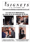
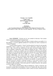
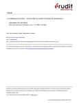
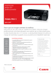
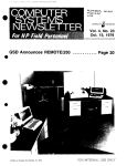
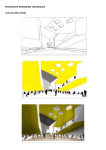
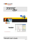
MARKTHAL
CONTROL
APP
PROJECT
REPORT
HONORS TRACK
LIGHT FORCE
K. Damen (0812615) and H. Sairanen (0824088)
M ARKTHAL C ONTROL A PP : AN USER FRIENDLY CONTROL APPLICATION FOR THE
L IVING L AB OF M ARKTHAL
Authors: K. Damen (0812615) and H. Sairanen (0824088)
A project report and description of the process behind Markthal
Control App
Technische Universiteit Eindhoven
Honors track Light Force
June 2015
A BSTRACT
Living Lab of Markthal is a light laboratory situated at the entrance
of the university library of the Technical University of Eindhoven.
The lab consists of a network of 64 LED fixtures and an everexpanding collection of sensors that collect and transmit data of the
movements of pedestrians in the area to a cloud network.
Connecting and controlling such large networks of light fixtures and
sensors is often troublesome and requires special software skills,
which makes operating the light settings challenging and timeconsuming. As a solution, an approachable easy-to-use mobile
application was suggested to make the threshold of using the lab
smaller.
The Markthal Control app was developed in collaboration with the
Intelligent Lighting Institute, two students from the Honors Track
Light Force and the OpenRemote Community. This paper will
discuss the process, application and implementation of the app in
practice. Also a brief overview to the specifications and system
architecture of the Living Lab are provided, to show how the app is
rooted in the system.
Page 1 of 33
1. I NTRODUCTION
The TU/e Intelligent Lighting Institute is an institute that
researches new lighting solutions in the field of intelligent lighting
and its implementation. ILI has three Living Labs in Eindhoven; one
in Stratumseind, one in the Main Building of the local technical
university and one at the front entrance of the university library.
The purpose of the Living Labs is to enable researchers to conduct
experiments and collect measurements in natural conditions as
opposed to controlled laboratory settings.
The first stage of the Living Lab of Markthal took place in 2013, and
the system consists now of over 500 individually controllable LED
lights in cold and white warm tones, spread across the large halfindoor hall (“Markthal”) in front of the university library. The
second stage of the project started in late 2014, when another LED
and sensor grid was planned above the main entrance of the
university library. The sensors and the light grids were installed in
place in the spring of 2015.
The LED grids in the system consist of 32 white light and 32 full
RGB fixtures. The lights are individually controllable via a control
device called the Pharos controller, which translates incoming
signals, such as a user changing the light program, into DMX
output for the light fixtures. Sensor data of bypassing people is
collected via four Kinect sensors and three high-end security
cameras. The input can be used for example for motion or presence
detection. All the communication between the sensors and the light
fixtures happens in the Markthal server through an online-based
open-source system called OpenRemote. This means that all
devices on the network can be accessed either through their
individual IP addresses or through the Pharos controller.
F IGURE 1: S IMPLIFIED
SYSTEM INFRASTRUCTURE
Even though the Markthal Lab consists of powerful sensors and
light fixtures and it is established through an elaborate network, in
its beginning situation it was lacking a simple-to-use tool for
Page 2 of 33
quickly shuffling through light programs and a toolkit for casual
users of the Markthal, such as party organizers to change the light
settings. The Markthal Control App provides a platform that is
implemented in the system architecture of the Markthal on a
fundamental level and yet provides the user the freedom of
operating the possibilities of the Living Lab setup. The application is
directly integrated in the OpenRemote server and it aspires to form
a complete collection of all light programs made by researchers at
the Living Lab. The end goal of the app is to make the Living Lab
accessible and easy to control, independent of the user’s skill level.
2. M ETHODOLOGY
The development of the application was started in early 2015 by
discussing the wishes and demands for the application with the
spokesperson of the client, P.R. Ross, MSc; the coordinator of the
Living Light Lab project. An important requirement for the
application was that it had to be accessible through mobile devices,
preferably by the use of the OpenRemote platform and above all, to
be simple, functional and attractive.
The study for the possibilities of the OpenRemote system was
started by contacting a mentor from the OpenRemote (from here
on referred to as OR) community, D.A.J. Willems, MSc. With the
help of Mr. Willems, we installed all the needed OR software on our
computers and set up accounts that were needed in order to access
the online-based designer toolkit.
In order to gain understanding of the platform, we conducted
several small experiments with the OR Designer and a Philips Hue
set, which consists of individually controllable light bulbs that
connect online via a bridge system. These experiments will further
be discussed in the Process section of this report.
The development of the final app was started after the physical
setup of the Living Lab was installed in place in mid-March. The
complete app and the user interface were created in the OR
platform, and the lights were controlled through communicating
with the Pharos controller from OpenRemote. The app is accessible
from online and mobile devices, once access to the Markthal server
is enabled with a username and a password. The complete progress
of the project is described under the Process header.
Page 3 of 33
3. P ROCESS
3.1 Small-scale implementation of the OR system
3.1.1 OpenRemote
The OR system is split in two separate sections; the Building
Modeler and the UI designer. Connections to lighting fixtures,
sensors, online input are filled in an input window (Fig. 2), where
information such as IP addresses, information protocol and
commands are filled in. Different kinds of data are filled in different
system presets; most important being Devices (artefacts connected
to the network), Commands (send a command to a device),
Sensors (retrieve data from a device) and Switches (toggle
between two states).
F IGURE 2: O PEN R EMOTE D ESIGNER , B UILDING M ODELER
SETTING UP A COMMAND .
VIEW :
The UI designer consists of a simple design platform where the
screen size of the (mobile) device is defined and objects, such as
buttons, switches or sliders are dragged on the interface.
3.1.2 Hue control system
As mentioned before, the process of developing the app was
started by first exploring in small-scale systems to gain a better
understanding of the working of the OR platform and the forms of
control it offers. In practice, this meant building up small systems
of Philips Hue lamps connected to the OpenRemote platform. The
goal of the test setups was to start with very small controls and
Page 4 of 33
building them up towards a larger goal. One of the very first
projects was controlling one single lamp. The functionality of this
very first app consisted of being able to turn the lamp on and off,
and adjusting its brightness and saturation. Picture 1 shows the
very basic user interface together with the UI designer and the
command row showing technical output of what the app user is
doing with the controls.
F IGURE 3: T HE
EARLY
H UE
PROTOTYPE IN THE
O PEN R EMOTE
PLATFORM
AND RUNNING ON A MOBILE DEVICE .
Setting up the Hue system in combination with a third-party
software (thus, not provided by Philips Hue) initially turned out
trickier than thought. No tutorials for similar systems were
available, so we made the system work together with our
OpenRemote mentor Don Willems. The main problem that occurred
during setting up the system was accessing the lights to their
individual IP addresses and logging on the protected system of the
lamps with specific user credentials. After fixing the initial
difficulties, the lamp system started working as planned. Figure 4
and 5 show the working of the lamp – the color change is purely
done by the app and requires no other controls.
After one-lamp tests, the system was expanded to cover all of the
6 freely available Hue lamps of the Breakout Area at Faculty of
Industrial Design. Later-stage tests included controlling all of the
lamps and programming a simple light program – blinking and
dimming – run across all the fixtures is if the light were a wave.
Page 5 of 33
F IGURE 4 & 5: T HE
H UE LIGHTS .
FUNCTIONING OF THE APP WITH THE TEST SETUP OF SIX
3.2 Markthal app
3.2.1 Functionality and goal
The building of the small test setups happened at the same time as
developing early sketches for the interface and the functioning of
the eventual Control App. Not only had this to do with efficient
planning, but also the eventual functions of the app. In order to
save time, we only build up small scenarios for situations that
would come across in the Control App. According to the initial
planning, the functionality of the app would cover the following
topics:
-
-
-
Interactive programs;
o Cross-line detection;
Pre-programmed stand-alone programs;
o The most interesting “test” programs from the Pharos
controller;
Manual settings;
o Master settings;
o Control of individual nodes (both RGB and IntelliWhite);
Video feeds of the three security cameras.
Page 6 of 33
F IGURE 6. C ONCEPTUAL
STORYBOARD OF THE USER EXPERIENCE AND THE
FUNCTIONING OF THE APP .
3.2.1 Connected devices
There are 32 Philips iWhite and 32 Philips ColorBurst RGB lights
installed in pairs. Furthermore there are three AXIS P1357 Network
cameras and sixteen Microsoft Kinect cameras placed.
F IGURE 7. F INAL
M ARKTHAL SYSTEM , AS
L IGHTING I NSTITUTE ( INTERNAL
CONFIGURATION OF THE
ILLUSTRATED BY THE
I NTELLIGENT
DOCUMENT ).
Page 7 of 33
The Philips iWhite lamps have warm and cool LEDs. The intensity of
the LEDs determines the warmth of the light. Resultantly, the color
temperature can range between 2700K and 6500K.
As the name suggests, the Philips ColorBurst RGB lights have red,
green and blue LEDs. It can be used to shine all the colors of the
rainbow. The lamps can deliver a luminous flux of up to 647
lumens.
The three AXIS P1357 Network Cameras are used to record all
activity on the area. The cameras are placed in such way that they
cover the whole area. There can be extra applications downloaded
for these cameras, for example a cross-line detector. This
application can be used to trigger programs.
Microsoft Kinect cameras are used to track movement of
pedestrians. Kinect has an RGB camera. More important: by the
use of an IR emitter and IR sensor, Kinect can capture depth
images. In addition to the movement tracker, the Kinect has a
microphone, which can be used to record audio as well as locate
the origin of the sound source and the direction of the sound wave.
3.2.2 User interface
The main objective for the user interface was to create an app that
is very clear and easy to use regardless of the user skill level. The
user interface was developed after a number of design cycles:
simple ink sketches were made to illustrate the panels that the end
user would see and navigate through. Eventually, the best option
for the interface was a simple layout that would sort the light
programs in three different categories: interactive, passive
(standby) and manual programs. Interactive programs mean
programs that combine sensor data with light effects, passive
standby programs are preset light programs retrieved from a
database and manual programs and purely created by the current
user by switching on and off light nodes in the grid. Every light
program style was given a tab in the main layout, to make the
programs easily accessible and easy to find.
F IGURE 8: E ARLY
CONCEPTUAL INTERFACE
Page 8 of 33
The user interface was created solely within OpenRemote because
of the simple integration process of the functionalities. As
mentioned before, the OpenRemote designer is split in two parts,
consisting of the UI Designer and the Building Modeler. The two
parts work seamlessly together and allow the user (developer) to
easily make layouts with the connected sensors, devices and
switches. Figure 8 shows one of the Control App screens (‘panels’)
in the UI Designer. All panels are grouped to corresponding folders,
which include a set of panels that can be navigated through by
swiping in the app.
F IGURE 9. A
MENU .
SCENE FROM THE
UI D ESIGNER , S TANDALONE
PROGRAMS
Furthermore, the user interface was designed to fit most mobile
devices, resulting in a panel size for mobile devices. Scaling up the
screens to perfectly fit any device turned out not possible within the
OpenRemote architecture, as all functions (navigation to other
screens, functions) were programmed on the user interface as
buttons sitting on top of a base image. Within OpenRemote, adding
functionality to a UI panel consists of dragging and dropping
elements in the panel area and separately connecting these to the
corresponding sensors, commands and devices. The Markthal
Control App only makes uses of buttons that execute a simple
command (“go to screen ‘Manual Programs’”; “play timeline 108”).
This made programming the screens relatively simple, but also
lacks the option of providing user feedback. This becomes a
problem mainly in the manual controls and the grid view (Figure 9,
third screen): for the user experience, it would be good to know
Page 9 of 33
which nodes are turned on or off and to smoothly switch between
the two modes on every individual node.
As visible in the differences between the early conceptual interface
and the definite app, some features were discarded due to technical
reasons. Programming interactive scenarios was not feasible within
the time frame of the project, and setting up programs that can
control the whole grid at once – like changing the brightness or
color of all nodes in the grid – also turned out to be much more
complicated than what similar features were in controlling smallscale hue systems. The layout of the app, however, was kept the
same and most of the initially planned elements also made it to the
final application.
Examples of screens of the final app are portrayed in Figure 9. The
example screens shown in the figure show the default start image,
standby program listing, master controls for the whole grid and the
individual node control for the red nodes.
A complete series of the app screens is to be found in Appendix A.
F IGURE 10. I MPRESSIONS
OF THE DEFINITE USER INTERFACE .
3.2.3 Process overview
The whole process behind the Control App ran relatively smoothly
with a number of bottlenecks. The first bottleneck was installing
and learning the OpenRemote software, as neither of us had ever
worked with a similar system before. The second bottleneck was
caused by the installing of the hardware of the Living Light Lab and
the setting up of the server. These two moments defined the main
milestones on the timeline behind creating the app.
The whole process from the first problem definition to a delivered
end product spanned from February 2015 to June 2015. The whole
process was controlled by a global timeline established in the very
start of the project. This global planning included all important
moments and tasks necessary to create the application and the
approximate working times for different phases. The document was
updated biweekly in order to track down the process. Throughout
Page 10 of 33
the whole project, this planning corresponded with the eventual
workflow relatively accurately.
On the other hand, during the project it became gradually more
clear that many of the functions planned for the app were more
complex to make functional than initially thought. Technical
difficulties such as the Markthal server crashing, software failing
and code that was sending out wrong signals to the light nodes
were not foreseen by the planning, causing delay to the end phase
of the project. In the initial planning, there was time reserved for
these kinds of unforeseen problems. However, the deadline of the
project was replaced two weeks prior to the initial deadline, leading
to the backup time being gone.
Because of these factors, some initially planned functionalities of
the app could not be realized in the given time frame. Even though
not including all the functionalities, the app was completed for the
major part (working user interface, standby programs, manual
programs, master settings, grid views, video feeds) and delivered
to the client with an extended user manual (included to this report,
Appendix B). The interactive programs were discarded from the app
after discussion with the client, as these were of a highly
experimental nature and had little significance for the functioning of
the app.
4. R ESULTS
The end product is a fully functional app that controls the lights in
the Markthal.
The first programs that were incorporated in the app were the
standalone programs. These passive programs are the testing
programs of the Pharos controller. Out of the 20 presets, seven
programs were incorporated to the app. All these standalone
programs display a predefined dynamic pattern.
F IGURE 11: T ESTING
THE STANDBY
PROGRAMS
Page 11 of 33
The presets used in the app were Pharos presets 1, 2, 6, 8, 9 and
16 (x2). These programs can be used at for example events where
certain mood lighting is desired. Due to the powerful lights, the
programs have a large impact on the atmosphere of the space, as
shows in Figure 11.
F IGURE 12: F OUR
OF THE STANDBY LIGHT PROGRAMS
Furthermore, manual settings were created to change the colors of
individual nodes. Every node can be set to red, green, blue and
cold and warm white. With the help of these color grids, the user
can set up their customized light settings according to their needs.
F IGURE 13: T ESTING
INDIVIDUAL NODE CONTROL WITH THE
B RABANT
FLAG
Page 12 of 33
Also, live video feeds of the three AXIS cameras are incorporated in
the Control App. The video feeds show the direct output of the
security cameras, which makes it possible to see the light patterns
on the asphalt and also the pedestrians moving in the area.
F IGURE 14: V IDEO
FEED AS SHOWN IN
THE WEB CONSOLE
VERSION
OF
THE
APP
A functionality that could not be realized within the time frame was
one example of interactive programs making use of the sensors
already installed to the system. This example program was
supposed to be a cross-line detection program, realized with the
security cameras coupled to the light grid.
Our client bought the license for using the cross-line detector
application for the AXIS security camera, so it could be
implemented in the app. Several weeks were spent on
understanding and realizing this feature. However, due to the
novelty of the technology and unstable AXIS software, this
application could not be realized within the time frame of this
project. However, similar programs will be created by the
Intelligent Lighting Institute.
Page 13 of 33
5. C ONCLUSION
The results of the Markthal Control App are promising. The Control
App functions as a pilot project for future implementation of
OpenRemote in Markthal and the simple controlling of the grid. The
app is the first simple tool for end users to control the system. Our
process of learning OpenRemote and implementing it to connect to
the Pharos controller and the LED grid provided the Intelligent
Lighting Institute valuable experience on the limitations of the
systems and on what kind of problems first-time users of the
systems can encounter.
Although it remains to be seen if the Markthal Control App will be
adopted by the researches or party organizers for controlling the
light system, the process of creating such an app and exploring the
possibilities of the systems was a truly interesting project.
Experiences gained during the project function as a valuable
resource for future projects in the Living Lab. The extended user
manual is also a valuable document for the Intelligent Lighting
Institute, as it is the first system-specific manual for the Markthal
installation with a low threshold and a simple explanation of
operating the complex systems of the light grid, Pharos and
OpenRemote together.
6. A CKNOWLEDGMENTS
We like to thank Philip Ross for his valuable coaching and feedback
throughout the project. His dedication and positivity was contagious
and that helped us to bring this project to such a nice end.
We would also like to thank Don Willems for his tips and tricks for
working with OpenRemote. Don was able to fix most of the
problems that occurred. If he didn’t know a solution at first sight,
he would always find a way to help us.
A PPENDIXES :
Appendix
Appendix
Appendix
Appendix
A: All screens of the Control App
B: User Manual Markthal Control App
D: Pictures of the app in use
C: Individual contributions of each member
Page 14 of 33
A PPENDIX A: A LL SCREENS OF THE C ONTROL A PP
Page 15 of 33
Page 16 of 33
Page 17 of 33
Page 18 of 33
A PPENDIX B: U SER M ANUAL M ARKTHAL C ONTROL A PP
This document is a user manual for the Markthal Control App. It will explain the key steps in order to
access the app on a laptop or on a mobile device.
Option 1: Access the app on a laptop
In order to access the control app on a laptop, type the following URL on your address bar:
http://OpenRemote-server.win.tue.nl:8691/webconsole/#main
The screen labeled “Controller List” will appear, in the shape of a mobile device. In order to open the
app controller, click on “Add”. Carefully fill in the info given out below.
Pictures 1 and 2: The web controller interface and the Add Controller tab.
Controller URL: http://OpenRemote-server.win.tue.nl:8691/controller
Default Panel Name: MarkthalAPP
Username: root
Password: markthal2015
Page 19 of 33
After this, the Markthal controller will appear in your controller list. Open Markthal Control App by
clicking on the address in the controller list.
The app shown in the virtual controller device has the exactly
same functionality as the mobile app. Toggle between
screens by clicking and dragging one side of the screen as if
you were swiping on a smartphone.
Accessing the Controller List is possible by holding the mouse
button down for two seconds and releasing. Resizing the
screen is possible from the left edge of the screen in the
menu that will pop open.
Picture 3: Control App as seen when accessing it on the web
interface.
Important note: the video streams of the cameras work on Safari and Firefox only.
Page 20 of 33
Option 2: Access the app on a mobile device
The mobile app functions on both iOS and Android platforms, and requires the installation of the
(free) OpenRemote app on the device and an internet connection on the tue-wpa2 network. The app
works on the following operating systems:
Android 1.5 or up
iOS 3.2 or later (iPhone, iPad, iPad mini, iPod touch)
Step one: Install OpenRemote
Download OpenRemote from Play Store (Android) or App
Store (iOS) and install it on your device. The application is
ready to use straight after installation.
Picture 1: OpenRemote in Play Store (Android 4.1)
Step 2: Connect to the Markthal server
The Markthal Control App is accessible within the OpenRemote platform and it connects to the same
server with all the sensors and light fixtures of the installation. In order to access the server, open
OpenRemote on your mobile device, turn Auto Discovery off and under the tab Choose Controller,
click on Add. Enter the following Controller URL in the window that opens:
http://OpenRemote-server.win.tue.nl:8691/controller (iOS)
OpenRemote-server.win.tue.nl:8691/controller (Android)
When you have connected to the server successfully, you will see a green check mark appear next to
the address (iOS only) on OpenRemote. The Android controller will not give an announcement of
successful connection, but gives an announcement “Current controller isn’t available” should the
controller URL be entered incorrectly.
Page 21 of 33
Pictures 2 and 3: OpenRemote app interface with the controllers
successfully installed (Android/iOS)
Should the app ask for log-in credentials, fill in the following:
Username: root
Password: markthal2015
Step 3: Open the app
In OpenRemote app, open the tab “Choose Panel Identity” and choose MarkthalAPP. When the
panel is chosen, click on “Done” in the main screen. The Control App will open and all light programs
and options are immediately at your disposal. Enjoy!
Pictures 4 and 5: Choosing the panel identity on Android and iOS
Page 22 of 33
In order to access the main menu of OpenRemote from within the app, shake the device (iOS) or
hold home button for a second and click on the icon Setting on the menu that opens from the lower
edge of the screen.
Important note: The video streams are not supported by Android devices and will lead to the app
crashing. In this case, reboot the app.
Developer options
Editing the app, for example adding more light programs, is done on the online platform of the
OpenRemote Designer. In order to edit the app, you need log-in credentials for the OpenRemote Pro
Designer. The OpenRemote Pro Designer is located at the following address:
http://designer.OpenRemote.com
Important note: This address is easy to confuse with the free version of the OpenRemote Designer,
which is located at designer.OpenRemote.org. The different versions have little difference at first
sight, but the Markthal controls are located on the professional version of the site. Therefore, please
make sure to use the correct domain name!
1. Getting started
The OpenRemote designer works with devices, commands and switches, all of which together form
the controls of the hardware and take care of communication with the whole system.
Communication with the light grid of Markthal happens through the Pharos controller, which is
already set up in the list of devices (Picture 6).
Picture 6: OpenRemote Designer, main
window of Building Modeler with the list
of commands already programmed in.
Page 23 of 33
In order to add a program, select the Pharos controller by clicking any command on the list below it
and click on New > Command. A new window opens, asking for command data. Fill in the following
in the gaps:
Name: Name without spaces
Protocol: UDP
IP address: 192.168.1.1
Port: 5005
Command: Pharos command in hexadecimal (see below)
Picture 7: The window for editing or
inserting new commands.
Important note: the Pharos commands need to be translated from ASCII to HEX, with small
adjustments. Every command must start with 0x and end to 0d. In order to illustrate this, here is an
example of one command correctly translated from ASCII to HEX:
Command: “node 081 will turn red with a fade of 2 seconds”
Pharos command in ASCII:
PHINTF081R255G000B000W000C000D02\r
Straight hexadecimal translation:
50 48 49 4e 54 46 30 38 31 52 32 35 35 47 30 30 30 42 30 30 30 57 30 30 30 43 30 30 30 44
30 32 5c 72 (these digits will be discarded)
Corrected hexadecimal translation:
0x5048494e544630383152323535473030304230303057303030433030304430320d
(discard the “5c 72” from the end; add 0x to the beginning and 0d to the end)
Page 24 of 33
After filling in the command info, press either “Submit” or “Submit and Continue”. The option
“Submit and continue” will remember the data in the fields for the next command, which is useful
when filling in large datasets, such as submitting a program for every individual node or device.
2. Pharos commands
Information stated here is courtesy of the Intelligent Lighting Institute. Text edited by Heidi Sairanen
and Koen Damen.
As mentioned before, the Pharos controller communicates with the rest of the system in specific
commands. Pharos commands are written in ASCII, which then needs to be translated to
hexadecimal from OpenRemote. This section will provide an overview of the most occurring
commands, as composed from internal design documents of the Markthal work group.
2.1 Forming commands
Pharos commands consist of a number of bytes that correspond to different pieces of information
sent to the device. Below, a few examples are written out to show how the ASCII code is formed. A
list of the most common commands available is listed in section 2.2 of this document.
Example 1: Play a preset timeline
Command: “start playing timeline 110”
The command consists of the following parts:
Byte 1 to 6
Byte 7 to 8
Byte 9 to 11
Byte 12
: “PHTRIG”
: 10
: Number of timeline
: “carrier return”
The command is simply constructed as a string of the bytes:
Form.
ASCII
HEX
Byte 1
Byte 2
Byte 3
Byte 4
Byte 5
Byte 6
Byte 7
Byte 8
Byte 9
P
50
H
48
T
54
R
52
I
49
G
47
1
31
0
30
1
31
Byte
10
1
31
Byte
11
0
30
Byte
12
\r
0d
The completed ASCII command is therefore PHT RIG10110\r, which can subsequently be translated
into hexadecimal as described in section 1 above.
Page 25 of 33
Example 2: Send commands to an individual node
Command: “set color of node 081 to red with a fade time of 2 seconds”
This command consists of a larger amount of information, as the color values of each color (redgreen-blue-warm white-cool white) of each node are individually specified for Pharos. The string
consists of the following digits in this order:
Byte 1 to 5 : “PHINT”
Byte 6 : “F”
Byte 7 to 9 : Address of an individual fixture (see 2.2.7)
Byte 10 : “R” (Red)
Byte 11 to 13: Value of red, 000-255
Byte 14: “G” (Green)
Byte 15 tm 17 : Value of green, 000-255
Byte 18 : “B” (Blue)
Byte 19 tm 21 : Value of blue, 000-255
Byte 22 : “W” (Warm white)
Byte 23 tm 25 : Value of w-white, 000-255
Byte 26 : “C” (Cool white)
Byte 27 tm 29 : Value of c-white, 000-255
Byte 30 : “D” (Set fade)
Byte 31 & 32 : Fade time 00 to 99 (s)
Byte 33 : “carrier return”
Again, the command in ASCII form is simply constructed by laying the digits into a single string:
PHINTF011R255G000B000W000C000D02\r
2.2 Command data
This section provides a quick overview of most common bytes needed for the command
strings.
2.2.1 General triggers:
001:
002:
003:
004 to 19:
Start up
Master ON
Master OFF
Reserved for light programs (described below)
2.2.2 Internal triggers:
20:
21 to 39:
Start timeline given in trigger 40.
reserved
Page 26 of 33
2.2.3 External control triggers:
40:
41:
42:
43 to 59:
UDP: start timeline, timeline number given by variable
UDP: Set the color of one device
UDP: Reset color settings of a device
reserved
2.2.4 External control feedback triggers:
60:
61:
62:
63 tm 79:
Which timeline = running
Which timeline = ended
Which timeline = released
reserved
2.2.5 Time-controlled triggers:
80 tm 99:
reserved
2.2.6 Preset programs (‘standby’)
101:
102:
103:
104:
105:
106:
107:
108:
109:
110:
111:
112:
113:
114:
115:
116:
117:
118:
119:
120:
RGB nodes display a rainbow flare while warm white nodes are on at appr. 25%.
Dynamic pattern of blue and white flashing lights.
Standby lighting: warm and cool whites are on at appr. 10%.
Red lights only.
Blue lights only. The lights will turn off after approximately 10 seconds.
Yellow lights flicker and all colored lights fade in and out in a pattern.
Pinkish white light. No warm white lights on.
Pink/white lights on the edges and red light in the middle. The lights change in
saturation very quickly as if they turn on and off.
Apparently affects only half of the lights (the four closest to the stairs and the last
eight). They become blue, while continuously fading in and out.
Similar to program 7, only more purple/pink in color.
Only the warm white lights fade in and out.
Warm white lights on.
Warm white lights flicker rapidly.
Only the first and last row (as seen from the stairs) softly flicker with warm white.
The same as program 12.
The warm and yellow/red lights fade in and out.
The same as program 7.
The warm white and colored lights flicker in turns. In the middle, white light
becomes red. (Similar to program 8.)
The same as program 9.
The same as program 10.
Still programs: 104, 105, 107, 110 and 112.
Dynamic programs: 101, 102, 106, 108, 109, 111, 113, 114, 116 and 18.
Page 27 of 33
2.2.7 Addresses of individual light nodes
Doors
Vertigo
011
111
211
311
021
121
221
321
031
131
231
331
041
141
241
341
051
151
251
351
061
161
261
361
071
171
271
371
081
181
281
381
Honors Room
Hoofdgebouw
For a complete list of all available controls and a more elaborate description on the Pharos presets,
please contact the Markthal workgroup.
3. Connecting commands to an interface
Once all the commands are set on OpenRemote, coupling them to the app is a very straightforward
process. In the main screen of OpenRemote, click on the icon “UI designer”. Creating new screens
and panels is a similar process to creating the commands. A new panel corresponds to a new “app”
that the user can choose when starting up OpenRemote, and a new screen is much like one tab of
the app under which they are located. The screens can be arranged to groups, which can be
navigated through by swiping to left and right. Navigation from a group to another needs to be set
separately, but this gives the option of creating tabs so that only panels related to each other can be
swept through at once.
Picture 8: Impression of the UI
Designer and the location of the
navigation icon “UI designer” on the
screen.
Page 28 of 33
When creating a new screen or altering an existing one, new functions can be added on the screens
simply by dragging buttons, switches and other elements from the right of the UI Designer. When
deleting existing elements from a screen, OpenRemote will ask for confirmation of deleting an
object, but actions cannot be reversed (in other words, there is delete, but no ctrl+z)!
Once a new element, such as a button with a function of turning a fixture on, is added on the screen,
the button can be coupled with the commands created earlier. Select the button, and look at Button
Properties on the right. Adding a command is as simple as pressing Select and finding the desired
command from the list of devices, commands and switches (Picture 9). If a button is meant for
navigating in the app, selecting a command is not needed. The navigation options are located under
Add Navigation, which offers options such as going to the next/previous screen or locating to a
specific panel within the app.
Picture 9: Example
of adding
functionality to a
screen, screenshot
from the free
OpenRemote
Composer.
Button designs and backgrounds of screens can be imported to the UI Designer in order to customize
the appearance of the application. Backgrounds can be added by clicking the empty screen, and
background options will show up on the right. Customized button designs can be imported via the
Image options in the Button properties. In order to make a button transparent, make a small empty
PNG file and change this to the button image.
Once the commands are coupled with the user interface, the app is already fully functional and can
be accessed as described in the first section of this manual.
Happy developing with the OpenRemote Designer!
Page 29 of 33
A PPENDIX C: P ICTURES OF THE APP IN USE
Page 30 of 33
Page 31 of 33
A PPENDIX D: I NDIVIDUAL CONTRIBUTIONS OF EACH
MEMBER
Koen Damen
From begin to the end, all the steps in the project were discussed together. Especially in the
beginning everything was done with the two of us, but near the end we often divided the workload.
Both of us had zero experience with OpenRemote. However, I already had experience with
programming and thus it wasn’t too difficult for me to work with this software. For Heidi this was
more difficult, since she had no experience as an architecture student. It was one of her goals to
learn to program. As a result I did most of the programming in the beginning and she did the most
programming near the end. I didn’t mind doing less of the programming at the end, since I realized
that I will probably not use this program in the future, because of its limitations and the non-userfriendly interface. Therefore I spent my time on other aspects, for example the communication with
the client and other people that were involved.
I did the most communication with the people that were involved in this project. Next to our project
coach, Philip Ross, we had to keep our contact person from OpenRemote, Don Willems, and our
Light Force track coach, Rombout Frieling, up-to-date. Not only through mail, but also by the use of
photos and videos I updated all “stakeholders”. After we finished the Philips Hue app I made a video
to inform the stakeholders about our progression (https://vimeo.com/130033691) and I created the
video for the Markthal Control App (https://vimeo.com/130015440) to show the result to the
stakeholders.
Also, I made a document with descriptions of all the test scenes of the Pharos controllers and I
digitalized the lay-out of the lights in a document as well. All of this was done to communicate the
information that we acquired during the project.
Additionally, we needed to contact other people from time to time whenever a specific problem
occurred. I did the most of this communication as well. For example when the server crashed, Michal
Rutka, a Certified Integrator of OpenRemote, and Ronald Domeni, Senior Engineer of Livingprojects,
had to be contacted.
To conclude, most parts of the process were divided fairly equal. I believe that this benefitted our
project, since we could strengthen each other. I believe that we couldn’t have achieved this result
without each other: good communication between the two of us was essential. Therefore I certainly
have the feeling that I contributed to the end result.
Page 32 of 33
Heidi Sairanen
Throughout the whole project, our workload distribution was relatively equal. Because of my study
background (architecture) I had little initial knowledge in programming and the technical side of light
fixtures, so I spent a lot of time in the beginning of the project trying to learn more about this. Both
of us read the book How to Smart Home (manual for using OpenRemote software in smart homes),
installed the OpenRemote software on our laptops and built up small systems with the hue lamp
systems.
In the pre-design state (testing hue systems and preparing for the real installation), I programmed
some of the small programs run in the lamps and made many of the simple interfaces that we used
for testing the programs. I also sought a lot of information in how to connect the lamps to the
OpenRemote system and pieces of code to make programs run. During this stage, I also made a lot
of conceptual system drawings exploring the relationship between the hue systems and the
Markthal grid. Making these sketches made it easier to understand the complex system
infrastructure and to make the leap from the small systems to the larger installation.
During the actual design stage, I also made a lot of sketches and initiatives for next steps of the
project. Koen and I composed the planning for the project together, and I was trying to keep the
tempo up by initiating work on our own time, such as each of us making three interface sketches and
conceptual program storyboards between meetings. I also made the template for making the
storyboards. These materials (storyboards and conceptual interfaces) were used for presentation
purposes and for developing the app further. Therefore, these were truly helpful tools in improving
the app. In the end, the user interface was designed by me for the most part, and I made the
template for the user interface screens and most of the screens themselves. I also designed and
made the intermediate presentation poster that presented our app.
In the programming phase of the system, I finalized the definite user interface, added navigation and
added most of the buttons for the different functions, including the 5x32 individual node buttons for
the grid views. I also helped generating the ASCII and hexacode translations for the commands of all
individual nodes, and tried to troubleshoot problems that occurred in the individual node control.
When Koen was plugging in these functionalities to the app and trying to program the cross-line
detection, I made the User Guide and wrote many of the sections in the project report.
In the end, during this project I learned to use the OpenRemote software confidently, learn to use
some functions of the Pharos controller and made my first user interface for an application ever. I
got to know some new technologies and definitely new aspects of light design. Seeing that in the
beginning of the project I had no programming knowledge at all, I have gone a long way since, and
working on this project proved itself helpful. Based on these factors, I would say that I contributed to
the overall process of the project and also to outcome very positively.
Page 33 of 33