1
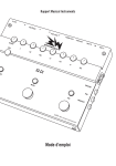
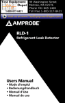
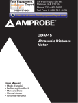
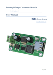
KMP7010
Ground Resistance Tester
Users Manual
KMP7010
Ground Resistance Tester
English
Users Manual
June 2011, Rev.1
©2011 Amprobe Test Tools.
All rights reserved. Printed in China
Limited Warranty and Limitation of Liability
Your Amprobe product will be free from defects in material and workmanship for 1 year from
the date of purchase, unless local laws require otherwise. This warranty does not cover fuses,
disposable batteries or damage from accident, neglect, misuse, alteration, contamination, or
abnormal conditions of operation or handling. Resellers are not authorized to extend any other
warranty on Amprobe’s behalf. To obtain service during the warranty period, return the product
with proof of purchase to an authorized Amprobe Test Tools Service Center or to an Amprobe
dealer or distributor. See Repair Section for details. THIS WARRANTY IS YOUR ONLY REMEDY.
ALL OTHER WARRANTIES - WHETHER EXPRESS, IMPLIED OR STAUTORY - INCLUDING IMPLIED
WARRANTIES OF FITNESS FOR A PARTICULAR PURPOSE OR MERCHANTABILITY, ARE HEREBY
DISCLAIMED. MANUFACTURER SHALL NOT BE LIABLE FOR ANY SPECIAL, INDIRECT, INCIDENTAL
OR CONSEQUENTIAL DAMAGES OR LOSSES, ARISING FROM ANY CAUSE OR THEORY. Since
some states or countries do not allow the exclusion or limitation of an implied warranty or of
incidental or consequential damages, this limitation of liability may not apply to you.
Repair
All test tools returned for warranty or non-warranty repair or for calibration should be
accompanied by the following: your name, company’s name, address, telephone number, and
proof of purchase. Additionally, please include a brief description of the problem or the service
requested and include the test leads with the meter. Non-warranty repair or replacement charges
should be remitted in the form of a check, a money order, credit card with expiration date, or a
purchase order made payable to Amprobe® Test Tools.
In-Warranty Repairs and Replacement – All Countries
Please read the warranty statement and check your battery before requesting repair. During the
warranty period any defective test tool can be returned to your Amprobe® Test Tools distributor for
an exchange for the same or like product. Please check the “Where to Buy” section on www.amprobe.
com for a list of distributors near you. Additionally, in the United States and Canada In-Warranty repair
and replacement units can also be sent to a Amprobe® Test Tools Service Center (see address below).
Non-Warranty Repairs and Replacement – US and Canada
Non-warranty repairs in the United States and Canada should be sent to a Amprobe® Test Tools
Service Center. Call Amprobe® Test Tools or inquire at your point of purchase for current repair
and replacement rates.
In USA In Canada
Amprobe Test Tools Amprobe Test Tools
Everett, WA 98203 Mississauga, ON L4Z 1X9
Tel: 877-AMPROBE (267-7623) Tel: 905-890-7600
Non-Warranty Repairs and Replacement – Europe
European non-warranty units can be replaced by your Amprobe® Test Tools distributor for a
nominalv charge. Please check the “Where to Buy” section on www.amprobe.eu for a list of
distributors near you.
European Correspondence Address*
Amprobe® Test Tools Europe
Robin-Amprobe® Test Tools UK
Beha-Amprobe GmbH
52 Hurricane Way
In den Engematten 14
Norwich, Norfolk, NR6 6JB
79286 Glottertal, Germany
United Kingdom
Tel.: +49 (0) 7684 8009 - 0
Tel.: +44 (0) 1603 25 6662 Fax.: +44 (0) 1603 25 6664
www.amprobe.eu
www.robin-amprobe.co.uk
*(Correspondence only – no repair or replacement available from this address. European
customers please contact your distributor.)
KMP7010
Ground Resistance Tester
6
1
2
7
3
4
5
8
9
1 LCD Display
6 Input terminals
2 LIGHT/LOAD button
7 Standard 3-Wires Test leads with
alligator clip (Red, Yellow, Green)
3 HOLD/SAVE button
4 TEST button
5 ON/OFF function
8 Auxiliary earth stakes
9 2 Wires test leads with alligator
clip (Red, Green)
KMP7010
Ground Resistance Tester
CONTENTS
SYMBOLS................................................................................................................2
UNPACKING AND INSPECTION .............................................................................4
FEATURES................................................................................................................4
OPERATION.............................................................................................................5
SPECIFICATION ......................................................................................................9
MAINTENANCE AND REPAIR.................................................................................10
Battery Replacement ........................................................................................10
1
SYMBOLS
Battery
�
Refer to the manual
T
Double Insulated
X
Caution! Risk of electric
shock
J
Earth Ground
�
Complies with EU
directives
=
Do not dispose of this product as unsorted municipal waste
�WARNING!
Do not operate this instrument in the presence of gasoline, natural gas,
propane, or in other combustible atmospheres.
Safety Information
• This operation manual includes the user guidance and safety instruction
when using the tester, please read it before using.
• Before using the Tester, please read and understand the operating
manual including the content.
• Must be followed all the related safety instructions, otherwise it may
cause accidents or damage the Tester.
• Using the Tester only as specified in this manual or the protection
provided by the meter might be impaired.
• Don not use the Tester or test leads if they appear damaged, or if the
Tester is not operating properly. If in doubt, have the meter serviced.
• Always use the proper terminals, switch positions, and range for
measurements
• Verify the Tester’s operation by measuring a known source.
• Do not use the meter around explosive gas or vapor.
• Replace the battery as soon as the low battery indicator appears.
• Remove test leads from the Tester before opening the battery door.
Safety sign “�“has 3 meanings in this manual, user has to pay attention to
this sign”�“for operation.
2
�DANGER!: identifies conditions and actions that most likely pose
hazard(s) or death.
�WARNING!: identifies conditions and actions that will pose hazard(s) or
death.
�CAUTION: identifies conditions and actions that will pose hazard(s) or
damage the Tester.
�DANGER!
• Do not use the Tester around explosive environment, which may cause
fire and explosion.
• Do not use the Tester in wet environment or do not make any
connection when your fingers are wet.
• Do not apply the load more than the Tester capacity or range.
• Do not open battery compartment while testing.
�WARNING
• Do not use the Tester if it is damaged or metal part is exposed.
• Do not disassemble the tester. If it needs repair, please refer to our
warranty statement.
• Do not change battery or open battery compartment when the Tester is
wet. Soft cloth should be used to dry it first.
• Make sure the Tester is turned off when changing battery or opening
the battery compartment.
�CAUTION
• Ensure test leads are properly inserted into the corresponding port
before measurement.
• Remove the batteries from the Tester if the tester will not be used for a
long time.
• Do not expose the Tester in extreme temperature and wet environment.
• Soft cloth and mild detergent should be used to clean the surface of the
Tester when servicing. No abrasive and solvent should be used.
3
Unpacking and Inspection
Your shipping carton should include:
1
KMP7010 Ground Resistance Tester
1
Test Lead (Green) with alligator clip
1
Test Lead (Yellow) with alligator clip
1
Test Lead (Red) with alligator clip
2
Auxiliary ground rods
2
Test leads (Red, Green) with alligator clip
6
1.5V Alkaline Batteries (AA)
1
Strap
1
User’s Manual
1
Carrying Case
If any of the items are damaged or missing, return the complete package to
the place of purchase for an exchange.
FEATURES
A properly functioning grounding system is a critical safety feature of the
electrical systems. It is used to mitigate the risk when exposed metal parts
come in contact with dangerous voltages in the event when insulation fails.
The building structures are protected by grounding systems to divert energy
of lightning strikes straight to ground. Connections to ground limit the buildup of static electricity when handling flammable products or when repairing
electronic devices.
ROBIN-AMPROBE Ground Testers are designed to measure resistance of the
grounding systems to verify that the system has low enough resistance to
provide protection for people, equipment and structures.
• Measures Earth ground resistance - 3 point (fall of potential) or 2 point
tests
• Voltage measurement prevents false measurements
• Test leads, auxiliary electrodes are included for complete instrument
• Data Hold
• Large, backlit display
4
• Built-in memory to store 20 measurement
• Low Battery Indication
• Supplied with: Three Test Leads (Green, Yellow and Red) with alligator
clip, Auxiliary ground stakes, two test leads with alligator clips
• Safety CAT III 400V
Range of application: This product is intended to be used to measure
installation in process plants, industrial installations, and residential
applications.
Operation
Preparation before measurement
Checking the unit on a known source before taking measurements.
Battery Voltage check:Select function from OFF to EARTH VOLTAGE or EARTH
“. Make sure the
RESISTANCE, LCD Display will show battery indicator : “
battery is at least at level 7.4~7.8V before making any measurement.
Battery sign
Battery Voltage
8.2V
7.8V~8.2V
7.4V~7.8V
7.0V~7.4V
7V
Test leads connection
Make sure all the test leads are firmly connected to the Tester input terminals;
If the test leads are not connected properly, the accuracy of the measurement
may be influenced.
Making Measurement
This product is intended to be used to measure installations in process plants,
industrial installations, and residential applications.
Measuring Range, Tolerance & Environment. (Temperature: 20±5°C; Humidity:
45%~75% RH; Altitude ≤2000 meter)
5
Earth Resistance Measurement
Display Range
Accuracy
0.00 – 40.00Ω
±(2% Rdg +20 LSD)
0.0 – 400.0Ω
±(2% Rdg +3 LSD)
0 – 4000Ω
±(2% Rdg +3 LSD)
Test Condition
Relative Humidity: ≤75%RH
Auxiliary Earth Resistance: 500e (Accuracy ±5%)
Earth Voltage: ≤10Vac
EN 61557-5 Measurement Range: 10Ω – 4000Ω ±(2% + 3LSD), f=840Hz
Interference voltages (3V) with system frequencies of 400Hz, 60Hz, 50Hz,
16 2/3Hz or with d.c. voltage across the terminals E and S or to the earth
resistance loop would have additional operating uncertainty. The overall
operating uncertainty B% is within ± 30%
Measurement times: approx. 1400 times or more (with fresh batteries)
Precision Measurement (using standard test leads for measurement):
1. place 2 ground stakes in earth/soil. Minimum distance between earth
electrode(E), probe(S) and auxiliary earth (H) should be 5-10 M (16- 33
FT) apart, shown in Fig.2
Note: Make sure that the earth stakes are inserted in a moisturized
soil. If the soil is too dry,add water to make it moist. Inserting the earth
stakes into rock or sand area also needs to moisturize the test area
before testing.
Red
Yellow
Green
5~10m
5~10m
Auxiliary
Earth Stakes
H: auxiliary electrode
Earthed Electrode
Under Test
S: potential electrode
Fig.2
6
E: earth electrode
2. Earth Voltage Testing: Turn the rotary switch to select EARTH VOLTAGE.
Connect the test leads to terminal V and E, and then connect to the
testing points. LCD display will display earth voltage value.
Voltage Measurement
Range
Accuracy
0 -400V AC, 50/60 Hz
±(1% Rdg + 6 LSD)
Note:Do not press the TEST button when measuring the earth voltage.
If the measuring value>10V, switch-off all related voltage equipments. Wait
until the earth voltage decrease, and then do it again. Otherwise, it may
influence the accuracy of earth resistance.
�WARNING!
Ground voltage testing only work in terminal V and E, H and S connecting
cable must be separated. Otherwise, it will cause danger and damage the
Tester.
3. Ground Resistance Testing: Turn the rotary switch to 40Ω or 400Ω or
4000Ω range,press”TEST”button, LCD display will show earth resistance
value. Choose the appropriate range depending on the earth resistance
value for better accuracy.
Note: when H or S does not connect properly, or earth resistance is out
of range,or testing terminal open circuit,LCD display will show”- - - - “,
7
Check the wiring connections, if soil is too dry, or if auxiliary earth
stakes are within the specified measurement distance. When the earth
resistance is greater than the selected measuring range, LCD display will
show “OL”(overload).
4. Auto Power Off: The tester will turn itself off after 10 minutes when in
idle.
5. Back Light: Press LIGHT/LOAD to turn ON or turn OFF the backlight.
6. Hold/Save Function: While testing, press ”Hold/Save” button,save data
function will be on, the displayed testing value will be saved and LCD
displays the corresponding sign. Press ”Hold/Save” button again to exit
this function.
7. Storage function:
a) Storage data: Press”Hold/Save”button for about 2 seconds. Storage
function will be on and save the corresponding data. Press “Hold/
Save”button again to save the 2nd data; press”Hold/Save”button
again to save the 3rd data and so on...,Press”Hold/Save”button for
about 2 seconds to exit this function.
b) Read data: Press”Light/Load”button for about 2 seconds to read the
saved data in memory. it will show number 01 saved data. Press”Light/
Load”button again to show number 02 saved data and so on (up to
20th saved data).To return to the previous saved data, press “Hold/
Save”. When ”Hold/ Save”button and ”Light/Load”button is working
as Up and Down selection button, pree “Light/Load” button for aout
2 seconds to exit this function.
c) Clear saved data: Press”Hold/Save”button and “Light/Load”button
simultaneously, then turn on the tester by rotating the ON/OFF dial
to any position. LCD display will show”C L .”, All data in the storage
memory will be deleted.
8
Simple measurement(use simple 2-Wires test leads for measurement): This
method will be used when the auxiliary earth stakes cannot be used. Use the
exposed earth resistance object from the ground as earth, like metal water
bath, water pipe, ground wire, building earth, also can use 2-wires test leads
method (E and S&H terminals).Connection diagram is as below:
Supply Transformer
Primary
Side
Secondary
Side
Reference Earthed
Electrode
Red
Green
Earthed Electrode
Under Test
SPECIFICATION
At Temperature: 20±5°C; Humidity: 45%~75% RH; Altitude ≤2000 meter)
Operating temperature: 5°C~40°C (32°F to 104°F)
Relative Humidity: ≤80%RH
Altitude: ≤2000 meter
Storage Condition:
A) Temperature: -20°C~60°C(-4°F to 152°F)
B) Relative Humidity: ≤90%
Product Size: 160mm x 101mm x 71mm (6.3 x 3.98 x 2.79in)
Product Net Weight: About 500g (1.1 lb)
CE Regulation Compliance:
EN 61010-1 CAT III 400V, EN 61010-2-31 for test leads
EN 61557-1, EN 61557-5
EN 61326-1 (EMC)
Pollution degree II, Class II equipment (double insulation)
IP40 as per EN 60529
9
MAINTENANCE AND REPAIR
If there appears to be a malfunction during the operation of the meter, the
following steps should be performed in order to isolate the cause of the
problem.
1. Check the battery. Replace the battery immediately when the symbol
“
” appears on the LCD.
2. Review the operating instructions for possible mistakes in operating
procedure.
Except for the replacement of the battery, repair of the meter should be
performed only by a Factory Authorized Service Center or by other qualified
instrument service personnel. The front panel and case can be cleaned with
a mild solution of detergent and water. Apply sparingly with a soft cloth and
allow to dry completely before using. Do not use aromatic hydrocarbons,
Gasoline or chlorinated solvents for cleaning.
Battery Replacement
Replace the batteries immediately after the low battery indicator appears on
the screen. Follow the steps below to replace the batteries:
1. Turn the rotary switch to OFF position
2. Remove the screws from the battery cover and open the battery cover
3. Remove the batteries and replace with 6 new 1.5V Alkaline Batteries
(AA). Pay attention to the polarity signs in the battery compartment.
4. Put the battery cover back and re-fasten the screw.
10