1
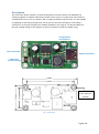
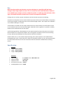
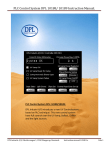
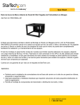
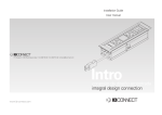
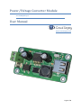
Power/Voltage Converter Module For the Raspberry Pi User Manual www.circuitsurgery.com Page 1 of 4 Description This small “bare board” module is a switch mode power converter based on the LM2576S-5.0 switching regulator is capable of delivering a stable 5 volts at up to 2.5 amps when connected to a suitable power source, such as a battery, with a voltage of between 8 and 35 volts. It is also capable of regulating an alternating voltage such as that from the secondary winding of a low voltage transformer. An AC input voltage to the module should be in the range of 7 to 28 volts RMS such that the rectified voltage to the regulator IC does not exceed its maximum voltage rating. On/Off Switch and Indicator Input Terminals Output USB Socket Input Fuse (Self-Resetting) Fig. 1 - Top view 63mm 4 x M3 Mounting holes, drilled to 3.25mm 24mm 31mm 55mm Fig. 2 - Dimensions Page 2 of 4 Use Note that the module may become very warm during use, especially with low input voltages and/or high output currents. This is normal, but care should be taken to place it on a suitable heat resistant and non-conductive surface. As with any electrical item of this type, the module should be located out of reach of unsupervised children. If fitting into an enclosure, proper ventilation must be ensured to prevent overheating Connection of the power source to the module is by means of the screw terminal block. The polarity of the input voltage is unimportant due to the on-board bridge rectifier. The output of the module is via a standard USB Type ‘A’ socket. A small switch is located near the output socket which turns the module on and off. When turned on, an indicator LED next to the switch will glow. Switched off, the regulator IC is placed in standby mode and the module draws less than 70µA. A self-resetting polyfuse is fitted adjacent to the input terminal to protect the power source from fault conditions on or beyond the module. Also, the regulator IC features internal current limiting circuitry and thermal shutdown for full protection from fault conditions. Should a fault occur, or the module stop functioning, then remove power to the module before investigating the cause. In the event that a fault has caused the polyfuse to trip, removing the power for a few minutes will restore the fuse. Check that the fault has been rectified before restoring power! Specification Physical Length 63mm (2.48in) Width 31mm (1.22in) Height 20mm (0.79in) Electrical Input Voltage Output Voltage Output Current No-Load Current Drain Standby Mode Current 8 – 35V D.C. or 7 – 28V R.M.S. A.C. 5 Volts D.C. Max 2.5A <10mA <70µA Page 3 of 4 © Circuit Surgery 2014. No part of this publication may be reproduced in any form, whether physically or electronically, without prior written consent. The Raspberry Pi name and the raspberry logo are trademarks of the Raspberry Pi Foundation. I have no affiliation with the Raspberry Pi Foundation. Page 4 of 4