1
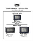
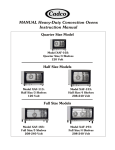
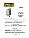
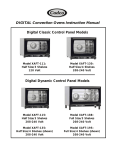
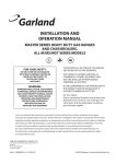
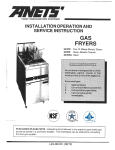
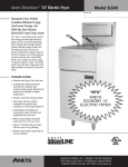
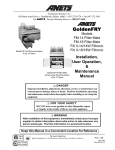
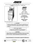
GPC-14/18/20
PASTA COOKER
GPC PASTA PRO
INSTALLATION & USER OPERATION MANUAL
GPC-18 shown with optional rinse station.
NOTICE!
After installation of your equipment, immediately contact your local gas supplier to
obtain information as to what action to take in the event that the user smells gas.
This information must be posted in a prominent location.
WARNING!
Improper installation, adjustment, alteration, service or maintenance can cause property damage,
injury or death. Read the installation, operating and maintenance instructions thoroughly
before installing or servicing this equipment
FOR YOUR SAFETY!
DO NOT store or use gasoline or other flammable vapors or liquids
in the vicinity of this or any other appliance.
KEEP THIS MANUAL IN A CONVENIENT LOCATION FOR FUTURE REFERENCE.
Anets, Inc PO Box 501, Concord, NH 03302-0501
Tel: 603-225-6684 Fax: 603-225-5231
L20-345 Rev 3
GPC-14/18/20
PASTA COOKER
SHIPPING CONTAINER INSPECTION
1.
Carefully examine the shipping container for external damage. If damage is noted, notify the delivery carrier immediately. Save all packaging
2.
If no external damage is noted, remove the unit from the shipping container and carefully examine it for damage. If damage is noted, place the
materials for claim examination.
unit in a safe location so that it can be inspected.
SPECIFICATIONS
SUPPLY PRESSURE†
MANIFOLD PRESSURE*
MODEL
INPUT BTU/H
GPC-14
111,000
GPC-18
160,000 / 80,000
NATURAL
PROPANE
NATURAL
PROPANE
ELECTRICAL REQUIREMENTS
3-1/2
IN. W.C.‡
10
IN. W.C.
MINIMUM
6 IN. W.C.
MINIMUM
11 IN. W.C.
120V, 50/60Hz SINGLE PHASE
GPC-20
* Measured at pressure tap on burner manifold.
† Measured at appliance input when all other gas powered equipment is operating.
‡ IN. W.C. = Inches, Water Column
A 115 Volt 3-pronged grounded plug is supplied with all gas units.
Refer to the inside door of the unit for the appliance wiring diagram.
LEG / CASTER INSTALLATION
1.
Carefully lay cooker on its back and install legs or casters as shown in diagram A below.
2.
After placing unit in installation area, adjust individual leg inserts to level cooker (so unit does not rock), by turning only the individual inserts.
Note: Appliances with casters must be secured with a restraining device to limit movement; refer to diagram B below.
Set the length of the restraining cable so
that the gas connector is not kinked when
the restraining device is fully extended.
Diagram A
Diagram B
Diagram C
A minimum 6-inch clearance is
required between the unit and the
site wall(s.)
GPC-14/18/20
PASTA COOKER
INSTALLATION INSTRUCTIONS
IMPORTANT!
Read all Installation Instructions carefully before starting the installation.
Failure to follow instructions may result in property damage, bodily injury or death.
DANGER!
When this cooker is not properly installed, a fire may result.
To reduce the risk of fire, follow all installation instructions.
1.
The installation must conform with local codes, or in the absence of local codes, with the National Fuel Gas Code ANSI Z223.1 latest edition,
CAN/CGA -B149.1 & B149.2, Natural Gas Installation Code as applicable including:
a.
The appliance and its individual shut off valve must be disconnected from the gas supply piping system during any pressure testing of
the system at test pressures in excess of ½ psig (3.45 kPa).
b.
The appliance must be isolated from the gas supply piping system by closing its individual manual shut-off valve during any pressure
testing of the gas supply piping system at test pressures equal to or less than ½ psig (3.45 kPa).
c.
For units utilizing optional floor casters, the installation shall comprise of a connector that complies with the Standard for Connectors for
Moveable Gas Appliances, ANSI Z21.69, or CAN/CGA 6.16-latest edition, and a quick-disconnect device that complies with the
Standard for Quick-Disconnect Devices for Use with Gas Fuel, ANSI Z21.41 or CAN1-6.9 “latest edition.”
d.
Adequate means must be provided to limit the movement of the unit without depending on the connector and the quick-disconnect
device or its associated piping to limit the appliance movement (when appliance is equipped with optional casters). The limiting cable is
supplied by the installation contractor. It is connected to the rear of the unit through the 5/16 dia. hole . The other end is attached to
the wall near the supply fitting. Refer to diagram B.
2.
For use only in non-combustible locations. Keep the appliance area free and clear from combustibles. Suitable for installation on non-
3.
The area that the unit is installed into should have provisions for an adequate air supply for proper burner operation and the flow of
combustible floors only.
combustion and ventilation air must not be obstructed. The bottom and back of the unit must be kept open so that the burners will be able to
draw enough air for proper operation. The area directly in front of the unit must be kept open so that the unit can be serviced.
4.
The appliance must be installed under a vent or exhaust hood to exhaust the cooking smoke and fumes and the products of combustion in
accordance with the Standard for Ventilation Control and Fire Protection of Commercial Cooking Operations, NFPA 96.
5.
The unit must be installed with the proper clearances to combustible materials; refer to diagram C.
NOTICE!
DO NOT pack required air spaces with insulation or other material.
6.
Make sure the unit’s pilot safety valve(s) are in the “OFF” position and turn on the main gas supply. Check for gas leaks using a soap
7.
Restrain the unit to prevent tipping when installed in order to avoid the splashing of hot liquid. The means of restraint may be the manner of
8.
This appliance is equipped with a 3-prong (grounding) plug and must be plugged into a properly grounded three-prong receptacle. Electrical
solution.
installation, such as connection to a battery of appliances, or installed in an alcove, or by separate means, such as adequate ties.
grounding must comply with local codes, or in the absence of local codes, with the National Electrical Code ANSI/NFPA No. 70, or the
Canadian Electrical Code, CSA C22.2, as applicable.
9.
Cooker drain terminates at drain valve. Connect plumbing per local and national codes.
10. After completion of proper hook-up and installation according to code, the unit may be operated.
NOTE: The installer should contact local building or fire officials concerning any installation restrictions or the need for inspection of the cooker
installation.
GPC-14/18/20
PASTA COOKER
OPERATING INSTRUCTIONS
IMPORTANT!
DO NOT light pilot or operate unit without water in the tank!
LIGHTING PROCEDURE
1.
Fill the tank with water to the appropriate level as indicated by the water level marks on the rear of the tank.
2.
Turn the gas safety valve knob to the “Pilot” position.
3.
Push and hold the knob down & ignite the pilot.
4.
Continue to hold the knob for 30 seconds or until the pilot flame does not drop out.
5.
Turn the gas safety valve to the “ON” position.
6.
Set the thermostat to the desired temperature.
7.
If the burners are accidentally extinguished or the gas safety valve shuts off due to pilot failure, turn off all valves.
Wait five (5) minutes before attempting to relight.
SHUT-DOWN PROCEDURE
When closing for the evening it is recommended that the unit be completely shut down.
1.
Turn the thermostat dial and power switch to the “OFF” position.
2.
Turn the gas safety valve knob to “Pilot.”
If the unit is to be shut down for an extended period of time, for service, or if it is desired to shut off the pilot:
3.
Turn the gas safety valve knob to “OFF”
4.
Turn the main gas cock to the off position (perpendicular to the gas line.)
IMPORTANT! Pilot must be turned off if cook tank is empty!
POWER BURST
18” and 20” Pasta Cookers are equipped with the “Power Burst System”. The Power Burst toggle switch is located on the front of the unit. Hard Boil
mode allows for high BTU input rate (160,000 BTU/H) for quick heating of tap water and heavy batch cooking. Soft Boil/Simmer mode sets the BTU
input rate at 80,000 BTU/H for accurate control of re-thermalizing and most cooking operations.
BATCH COOKING
1.
Place the batch cooking basket (optional) on the basket hanger. If the unit is equipped with an optional timer control, set the time for batch
2.
With basket in the boiling water, add 6 pounds of dry pasta into basket. 6 pounds of dry pasta becomes approximately 15 pounds of cooked
3.
Stir gently as needed to keep pasta separated.
4.
When cooking is complete, remove the basket from the water. Immediately rinse with cold water to remove excess starch and stop the
cooking and push the timer to activate (approximately 8-10 minutes.)
pasta or about (24) 10oz servings.
cooking process.
RETHERMALIZING
1.
Set the thermostat to 160-190°F.
2.
Reheat time is approximately 30 seconds for individual portions.
Individual portion baskets and rack are available as an accessory from Anetsberger Brothers Inc.
GPC-14/18/20
PASTA COOKER
CLEANING & MAINTENANCE
DANGER!
Avoid moving the unit while it contains hot liquid. Drain the liquid before cleaning or servicing.
DAILY CLEANING
1.
Follow shutdown procedure and allow hot water to cool.
2.
Disconnect the power supply.
3.
Open the front door and thread the drain valve extension into the drain valve.
4.
Slowly open drain valve and drain water. CAUTION: HOT WATER!
WARNING!
Wait until the tank has cooled before performing step 5 to avoid injury from burns.
5.
Wipe out and rinse tank.
6.
Close drain valve and remove extension.
7.
Refill tank with clean water.
8.
Follow the lighting procedure.
NOTE: The cooker automatically shuts off the burners when you open the door so that they cannot fire.
After draining or maintenance, close the door and reset the unit by turning the power switch off and then on.
MONTHLY MAINTENANCE
1.
Each month, before operation, check the exhaust flue to ensure that it is clear of debris and obstructions allowing exhaust gases to flow freely
toward the ventilation hood area. DO NOT allow the flue area to become excessively dirty.
2.
Observe the condition of the ventilation hood. If it shows evidence of a great deal of greasy residue, remove (clean) the residue to allow free
3.
Check the burner tube baffles (located inside the burner tube on 18”/20” tube fired models) to ensure that they are not deteriorated beyond
flow of ventilation air.
their useful life. If baffles need to be replaced, contact the factory, a factory representative or a local service company for replacement.
SERVICE INSTRUCTIONS
DO NOT OPERATE UNIT IN THE EVENT OF A POWER FAILURE.
1.
Follow the shut-down procedure in the event of a prolonged power failure.
2.
Disconnect the power supply before service or maintenance.
3.
When supplied with casters, a restraining device should be in place. If disconnection of the restraint is required, reconnect the restraint after
4.
To avoid splashing of hot liquid, before removing the unit from its originally installed location:
the appliance has been returned to its originally installed position.
a.
5.
shut down the unit in accordance with the shut down procedure
b.
close all valves
c.
allow to cool
d.
drain the liquid
e.
disconnect the restraining device
Contact the factory, a factory representative, or local service company to perform maintenance or repairs.
GPC-14/18/20
PASTA COOKER
TROUBLESHOOTING
PROBLEM
Water is cold
(Burners not firing)
Thermostat 25º F or more below the knob
set point.
Pilot will not remain lit.
CAUSE
SOLUTION
No gas supply
Open all gas cocks supplying the unit.
Inadequate gas supply
Adjust the pressure regulator for 3.5 inches W.C.
manifold pressure for Natural Gas and 10 inches
W.C. for L.P. gas, with the burners firing.
No Pilot
Follow lighting instructions under LIGHTING
AND SHUT DOWN section.
Safety valve knob is in the “Pilot” position
If the pilot is burning turn the knob to the “ON”
position.
Thermostat is set too low.
Turn the thermostat knob to a higher set-point.
Low supply gas pressure.
Check incoming gas pressure.
Defective thermostat
If the pilot is burning, the safety valve knob is
“ON”, and the thermostat knob is at the highest
set-point, the burners should be firing. If not,
replace the thermostat.
Loose wiring
Check wires to make sure they are intact, and
tighten all connections
Pilot flame is too small and will not heat the
thermopile.
Adjust the pilot needle valve on the gas safety
valve to the full open position (it is located under
the slotted screw). To adjust, remove the slotted
screw turn the inside needle valve open
(counter-clockwise) two turns. Replace the outer
screw.
Dirty pilot burner
Remove pilot burner and clean.
High-limit safety activated
Allow water to cool for 15 minutes, then follow
lighting instructions
High-limit safety defective
Jump out high limit. If pilot then lights, replace
high limit.
WA RNING!
DO NOT return the fryer to operati on with its high limit thermostat bypassed!
Burner flames too large.
Thermopile is defective.
(Thermopile should generate at least
250mV)
Replace the thermopile.
Gas safety valve is defective.
Replace the gas safety valve
Main gas valve pressure regulator set too
high.
Reduce the pressure by adjusting the pressure
regulator. To reduce the pressure, turn the
adjusting slot counter-clockwise. The adjusting
slot is located under the regulator slotted cap.
GPC-14/18/20
PASTA COOKER
TROUBLESHOOTING - AUTOMATIC LIFT MECHANISM
PROBLEM
Basket does not lower when the
timer control pushbutton is
pressed after the knob is set to a
time value.
Basket does not raise after the
timer reaches a value of zero.
CAUSE
SOLUTION
Power is not provided to unit.
Ensure supply circuit breaker is “ON” and unit’s power cord is
plugged in.
Power switch is not switched on.
Switch to ON position.
Loose wiring connections.
Check wiring and tighten all connections; especially timers, lift
motors and microswitches.
Timer has failed.
Set a time value using the timer control knob and depress the
push button. If the basket does not lower, jump the timer
terminals marked “C” (white wire) and “NO” (right motor – blue,
left motor – brown.) If the motor operates, the timer is has failed
and must be replaced. If the motor does not operate, the
microswitch or motor may have failed.
Microswitch has failed.
Set a time value using the timer control knob and depress the
push button to start the timer operation. Check for 120V at the
microswitch by metering between the “C” terminal (white wire)
and the “NO” terminal (right motor – brown, left motor – black.) If
no power is present between the terminals the microswitch is
defective and must be replaced. If power is present and the
motor does not operate, the motor must be replaced.
Lifting mechanism or motor has failed.
If the motor operates but the basket doesn’t raise, observe
whether or not the motor crank assembly moves. If the crank
does not move but the motor shaft is spinning, the shear pin in
the shaft has broken and must be replaced.
If the motor operates but the shaft does not turn, the motor
gears have failed and the motor needs to be replaced.
If the motor does not operate, check for 120V power at the
motor terminals. If power is present and the motor does not
operate, the motor has failed and must be replaced.
Microswitch has failed.
See above.
Timer has failed.
See above.
Basket lowers and raises
repeatedly.
Microswitch is improperly positioned.
Position the microswitch properly.
Basket raises after the timer has
reached a value of zero, but then
sinks back into the tank.
Lift motor has failed.
Replace the lift motor.
NOTES:
In the event of problems with or questions
about your order, please contact the Anets
factory at:
(603)-225-6684 World Wide
Website Address: www.anets.com
In the event of problems with or questions about
your equipment, please contact the Anets
Authorized Service and Parts representative
(ASAP) covering your area, or contact Anets
at the number listed to the left.
MAILING ADDRESS – P.O. BOX 501, CONCORD, NH 03302-0501
SHIPPING ADDRESS – 10 FERRY STREET, CONCORD, NH 03301
L20-345 R3