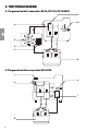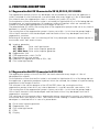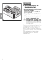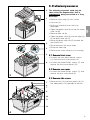
1
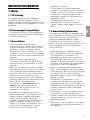
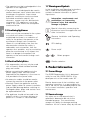
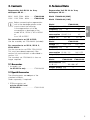
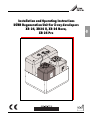
Installation and Operating Instructions
DÜRR Regeneration Unit for X-ray developers
XR 24, XR24 II, XR 24 Nova,
XR 24 Pro
2006/01
Content
Important Information
1. Notes ........................................................ 3
1.1 CE - Labeling .................................... 3
1.2 Electromagnetic Compatibility ........... 3
1.3 General Notes ................................... 3
1.4 General Safety Information ............... 3
1.5 Combining Appliances ..................... 4
1.6 Electrical Safety Notes ..................... 4
1.7 Warnings and Symbols .................... 4
2. Product information .............................. 4
2.1 Correct Usage .................................. 4
2.2 Incorrect usage ................................ 4
3. Contents .................................................. 5
3.1 Accessories ...................................... 5
3.2 Special Accessories ......................... 5
4. Technical Data ........................................ 5
5. Functional Diagram ............................... 6
5.1 Regeneration Unit connected to
XR 24, XR 24 II, XR 24 NOVA ........... 6
5.2 Regeneration Unit connected to
XR 24 PRO ........................................ 6
6. Functional Description ......................... 7
6.1 Regeneration Unit RU 24
connected to XR 24, XR 24 II,
XR 24 NOVA ..................................... 7
6.2 Regeneration Unit RU 24
connected to XR 24 PRO ................. 7
Installation
7. Set-up alternatives for
Regeneration Unit .................................. 8
8. Preliminary measures ............................ 9
8.1 Remove front cover .......................... 9
8.2 Remove rear cover ........................... 9
8.3 Remove side covers ........................ 9
9. Hose connections ................................ 10
10. Electrical connections ......................... 11
10.1 XR 24, XR 24 II, XR 24 NOVA ......... 11
10.2 XR 24 PRO ...................................... 11
11. Setting the Regeneration Electronics12
11.1 XR 24 ............................................... 12
11.2 XR 24 II and XR 24 NOVA .............. 13
11.3 XR 24 PRO ...................................... 14
12. Check Settings ..................................... 15
12.1 XR 24, XR 24 II, XR 24 NOVA ........ 15
12.2 XR 24 PRO ...................................... 15
13. Setting Regeneration Pump
Piston Stroke ........................................ 16
14. Commissioning .................................... 16
Operation
15. Cleaning the Regeneration Unit ........ 17
15.1 XR 24, XR 24 II, XR 24 NOVA ......... 17
15.2 XR 24 PRO ...................................... 17
16. Cleaning the X-ray Developer ............ 17
17. Disposal of Chemicals ........................ 17
Troubleshooting
18. Troubleshooting Tips for XR 24,,
XR 24 II, XR 24 NOVA ............................ 18
19. Troubleshooting Tips
XR 24 PRO ............................................ 19
2
IMPORTANT INFORMATION
1. Notes
1.1 CE - Labeling
This product bears the CE- Labeling in
accordance with the guidelines of the
Medical Products Committee 93/42/EWG and
satisfies all criteria of the Appendix I to said
guidelines.
1.2 Electromagnetic Compatibility
• This product conforms to all requirements
laid down for Electromagnetic Compatibility
of Medical Appliances.
1.3 General Notes
• These Installation and Operating
Instructions form an integral part of the unit.
They must be kept close to the unit and in
readiness whenever required. Precise
observance of these instructions is a precondition for use of the unit for the intended
purpose and for its correct installation and
operation.
These Installation and Operating
Instructions should be passed on to any
future purchaser or explained to any new
operator.
• Safety for the operator as well as troublefree operation of the unit are only ensured if
use is made of original equipment parts.
Moreover, use may only be made of those
accessories that are specified in the
technical documentation or that have been
expressly approved and released by Dürr
Dental for the intended purpose.
Any warranty or guarantee becomes
invalid in the case where parts or
accessories are used which are not
supplied by Dürr Dental.
• Dürr Dental only regard themselves as
being responsible for the equipment with
regard to safety, reliability and proper
functioning if assembly, resettings,
changes or modifications, extensions and
repairs have been carried out by Dürr
Dental or an agency authorized by Dürr
Dental and if the equipment is used in
conformity with the Installation and
Operating Instructions.
• The developer unit herein described
conforms to the relevant safety standards
valid at this time. All switches, processes,
trade marks, software programs and
appliances named in this document are
registered names.
• Any reprinting of the technical
documentation, in whole or in part, is
subject to prior written approval of Dürr
Dental.
1.4 General Safety Information
This appliance has been so designed and
constructed by Dürr Dental that any danger
arising from the use of this product is
virtually excluded provided it is fitted
according to the instructions. However, in
order to avoid any possible damage or injury
we are obliged to point out the following
safety measures.
• When operating this appliance all local
rules and regulations must be observed!
Any modification whatsoever is not
permitted: any guarantees covered by
Dürr Dental thus become invalid. In the
interests of ensuring problem-free running
the owner and operator are responsible for
observing all rules and regulations.
• Retain all packing material for possible
return of the product to the manufacturer.
Take care that it does not fall into the hands
of children. Only the original packing
guarantees optimal safety of the appliance
during transport.
Should return of the product to the
manufacturers be necessary during the
guarantee period, Dürr Dental accepts no
responsibility for damage occurring during
transport where the original packaging
was not used!
• This product is a technical appliance and
may only be installed and operated or
used by someone who has been trained or
who has experience of how to use the
appliance correctly.
• Before every use the operator must check
the functional safety and the condition of
the appliance.
3
• The operator must be knowledgeable in the
operation of the appliance.
• The product is not designed to be used in
medical treatment areas where there exists
the danger of explosion. Areas where
explosions could occur are those where
flammable anesthetic material, skin
cleansers, oxygen and skin disinfectants
are present. This appliance is not to be
used in any areas where the atmosphere
could cause fire.
1.7 Warnings and Symbols
In the Installation and Operating Instructions
use is made of the following terms or
symbols to denote information of special
importance:
Information, requirements and
prohibitions on preventing
personal injury and extensive
damage to propert.
Special information concerning the
economical use of the appliance and
other instructions.
1.5 Combining Appliances
• Units may only be connected to the system
or to other units when it has been
established that there is no reduction of
safety for the patient, the operator or the
environment through such connection.
Where it is not absolutely clear from the
documentation whether the safety is
reduced by such connection, then the
operator must establish, e.g. by contacting
either the manufacturer or an expert, that
there is no danger to the patient, the
operator or the environment through such
connection.
1.6 Electrical Safety Notes
• This regeneration unit may only be used
with a correctly fitted standard earthed
plug and socket.
• Before connecting the appliance to the
power supply check that the current
required and the frequency is the same as
that provided at the power outlet.
• No extension cables should be used to
connect the machine to the power outlet.
• Warning! Check the appliance and the
power supply cables for correct installation
and possible damage before switching on.
Damaged cables, plugs and sockets must
be replaced before use.
• The appliance should not be used in the
patient’s vicinity. A minimum distance to
patient of 1.5 meters is recommended.
4
Observe Installation and Operating
Instructions
CE-Labeling
Power on/off
/
Select program
Confirm selection
2. Product information
2.1 Correct Usage
The DÜRR Regeneration Unit is designed
solely for use with DÜRR DENTAL X-ray
developer units of the model series XR .. .
Precise observance of the installation and
operating instructions is a pre-condition for
use of the unit for the intended purpose and
for its correct installation, operation and
maintenance.
2.2 Incorrect usage
Any other use or use beyond what is
specified is deemed to be not for the
intended purpose. The manufacturer
accepts no liability for damage resulting
therefrom. All risk is borne solely by the user.
3. Contents
4. Technical Data
Regeneration Unit RU 24 for X-ray
developers XR 24 .. .
Regeneration Unit RU 24 for X-ray
developers XR 24 .. .
230V - 240V, 50Hz - 60Hz ........ 1700-820-00
100V - 110V, 50Hz - 60Hz ........ 1700-830-00
Model 1700-820-00 (230V)
Before connecting the regeneration
unit to the developer please make
sure to check the following:
Is the regeneration unit to be
connected to a developer of the
model XR 24, XR 24 II, XR 24 NOVA
or
to an XR 24 PRO?
For connection to an XR 24 PRO:
Use the assembly set 1700-284-00 (included)
For connection to an XR 24, XR 24 II,
XR 24 NOVA:
Use the conversion set PCB 1700-212-00!
This must be ordered separately. See
section 3.2 and installation as described in
section 11.2.
The assembly set 1700-284-00 is then no
longer required.
Model 1700-830-00 (110V)
Model
1700-820-00
Voltage (V)
230 - 240
230
50
60
Frequency (Hz)
Power
consumption (A)0.65 / 0.9
Output (W)
0.5
50 - 80
Model
50 - 80
1700-830-00
Voltage (V)
100 - 110
100 - 110
50
60
Frequency (Hz)
Power
consumption (A) 0.8 / 1.0
Output (W)
Model
0.6 / 0.75
40 - 80
40 - 80
1700-820-00
1700-830-00
Measurements (cm)
3.1 Accessories
LxBxH
1 Assembly set
for XR 24 Pro only ................ 1700-284-00
Weight (empty) (kg)
32 x 36 x 37
4
3.2 Special Accessories
The following parts are not part of the
standard contents.
Order separately if required!
1 PCB conversion set,
only for XR 24 II and
XR 24 NOVA ........................... 1700-212-00
5
5. FUNCTIONAL DIAGRAM
5.1 Regeneration Unit connected to XR 24, XR 24 II, XR 24 NOVA
A1
A2
H
30
20
D
40
10
50
50% OFF
S1
0
REG.
60
100% ON
G
C
B
5.2 Regeneration Unit connected to XR 24 PRO
J
A
H
I
B
6
6. FUNCTIONAL DESCRIPTION
6.1 Regeneration Unit RU 24 connected to XR 24, XR 24 II, XR 24 NOVA
The regeneration pumps of the X-ray developer are activated every time that the appliance is
initially switched on and, furthermore, are reactivated after every length of 1.3m of developed
film material when the regeneration switch is correctly set (switch (C) to ON).
For the duration of time that the film intake is activated (via light barrier H) on a film being fed into
the appliance, an impulse generator (A) produces rotational impulses which are counted, the
number of impulses being proportional to the length of the film.
The potentiometer (D) allows the running time of the regeneration pumps to be set at any interval
between 0 s and 60 seconds.
The running time of the regeneration pump is factory set at 30 s. In this time the pumps feed c.
190 ml fresh chemicals into the developer and fixer baths of the X-ray developer from the 5l
regeneration canisters.
Switching off the pumps, and / or switching off the X-ray developer transmits a delete impulse to
the counter which then resets at zero.
A) Impulse generator
A1) XR24:
Drive shaft light barrier
A2) XR24 II:
Drive motor impulse generator
A2) XR24 Nova: Drive motor impulse generator
B) Regeneration Unit
C) PCB regeneration switch On/Off
D) Potentiometer for time setting
G ) Reduction of regeneration time to 50% / 30s
H) Film intake light barrier
6.2 Regeneration Unit RU 24 connected to XR 24 PRO
The regeneration pumps of the XR 24 PRO are reactivated after every length of 1.3m of
developed film material.
For the duration of time that the film intake is activated (via light barrier H) on a film being fed into
the appliance, a generator produces impulses which are counted, the number of impulses being
proportional to the length of the film.
The software in the service program of the XR 24 PRO allows the running time of the
regeneration pumps to be set at any interval between 0 s and 60 seconds, see section 11.3.
The running time of the regeneration pump is factory set at 30 s. In this time the pumps feed c.
190 ml fresh chemicals into the developer and fixer baths of the X-ray developer from the 5l
regeneration canisters.
The switching off of the pumps after a regeneration phase automatically transmits an impulse to
the counter which then resets at zero. The current counter reading is stored whenever the X-ray
developer is swiotched off or in case of a power down.
A)
B)
H)
I)
J)
Drive motor impulse generator
Regeneration Unit
Film intake light barrier
PCB
Display
7
INSTALLATION
7. Set-up alternatives for
Regeneration Unit
• Set-up of Regeneration Unit RU 24 next
to the X-ray developer:
Where sufficient space is available, this
set-up is preferred.
• Set-up of Regeneration Unit RU 24 in a
cupboard:
The operator must be instructed to check
the state of the chemicals regularly.
1
Set-up of Regeneration Unit
RU 24 above the level of the X-ray
developer is not permissible. This
set-up position makes it possible
that chemicals leak into the X-ray
developer baths.
Please ensure that all connecting hoses from
the Regeneration Unit RU 24 to the X-ray
developers are laid without any twists or
bends. The distance between Regeneration
Unit and X-ray developer should not exceed
2m.
When setting-up the X-ray developer,
ensure good access to it and to the
collecting tanks.
8
8. Preliminary measures
2
The following measures need only be
taken when the Regeneration Unit is
subsequently being connected to a X-ray
developer.
1
• Remove mains plug (1) from socket
• Lift cover (2)
• Drain any chemicals from the X-ray
developer
• Open the green catch (3) on the film intake
roller set (6)
• Remove roller set (6)
• Open the green catch (3) and the clips (4)
of the dryer roller set (5)
2
3
• Swing the dryer roller set (5) towards the
rear and lift out
• Rinse the baths with warm water
4
• Close the water tap
• Remove the cover necessary for working
5
8.1 Remove front cover
• Unscrew the two quick-release screws
(11) from the front cover panel (12)
6
• Unscrew the three Philip’s screws (7) and
remove the front cover panel (12)
8.2 Remove rear cover
• Unscrew the three Philip’s screws (7) and
remove the rear cover panel (9)
3
8.3 Remove side covers
7
• Remove front (12) and rear panels (9), lift
the side panels (10) upwards to remove
8
7
9
10
11
12
4
9
9. Hose connections
9.1 Hose connection to XR24, XR 24 II,
XR 24 NOVA or to XR 24 PRO
with serial number up to T005999
The regeneration connection is
effected using the nozzles to the tank
at 16E and 16F, see figs. 6 and 7.
13
14 • The connecting hose from the Regeneration
Unit for developer (black) (13) and fixer
(red) (14) must be slipped through the
prepared holes on the rear of the machine
and fed to the grey connecting sleeves
(16E) and (16F) on the baths.
• Uncsrew the locking nuts (18) on the
connectors (16E) and (16F).
5
• Remove the black plugs (20). Slide the
locking nuts (18) and the grey hose
locking ring (19) onto the connecting hose
(13), and (14). Slide the connecting hose
for developer (black) (13) and fixer (red)
(14) all the way onto the appropriate
connector sleeve, (16E) and (16F), of the
bath and secure in place with the locking
nut (18).
16E E Developer bath
16F
F Fixer bath
9.2 Hose connection to XR 24 PRO
with serial number from T006000
The tank design has been optimised
and the regeneration connection is
effected at the inlet pipe, see fig. 7a.
Use the assembly set 1700-284-00 “inlet
pipe for regeneration unit” with enclosed
assembly instructions.
6
16E
16F
1
F
E
18
13
14
➜
19
20
➜
2
5
6
7
10
7a
10. Electrical connections
10.1 XR 24, XR 24 II, XR 24 NOVA
• Place the appliance plug into the socket
(15a) to the rear of the X-ray developer
and secure in place with the locking screw.
15a
8
10.2 XR 24 PRO
• Remove socket cap (15b) to the rear of the
X-ray developer.
15a
• Use the connection port (15a) from the
assembly set provided – 1700-284-00.
• Put connection port into the prepared
opening using the 4 screws.
• Connect the cable set as illustrated (Fig. 9).
• Place the Regeneration Unit plug in the
socket and secure in place with the locking
screw.
15b
8a
Circuit diagram XR 24 PRO
X1/X2 Plug
X3
Regeneration Unit
1700-216-50
9
11
11. Setting the
Regeneration Electronics
Before setting, fill the X-ray developer baths with water.
The pump running time should be set
according to the individual requirements of the surgery.
We recommend, for example, that
where a large number of films are developed the regeneration time should
be lowered in order to avoid unnecessary consumption of chemicals.
11.1 XR 24
Switch „S1“ ON / OFF:
• If switch (22) is set to OFF, regeneration
will take place after 1.3m of developed film.
• If switch (22) is set to ON, then
additionally regeneration will take place
every time the appliance is switched on.
Switch „S1“ 50% / 100%:
• If switch (21) is set to 100%, then the
maximum pump running time of the
Regeneration Unit is 60s.
• By turning the switch (21) to 50% then the
maximum pump running time of the
Regeneration Unit is halved to 30s.
Potentiometer „REG“ regeneration time
The amount of chemical transported to the
X-ray developer depends on the pump
running time of the Regeneration Unit.
The potentiometer (23) can be used to set
the pump time from >0s to <60s (<30s).
The pump operating time is factory-set at
30s. In this time approx. 190ml fresh
developer and fresh fixer are pumped to the
baths of the X-ray developer. If further
adjustment is necessary the potentiometer
knob (23) can be used to change the pump
operating time.
10
C19
C20
C18
V 74
R 67
R 59
30
20
R60
40
50
50% OFF
StartReg.
11
12
REG.
60
C23
S1
0
R 61
10
21
22
100% ON
23
11.2 XR 24 II and XR 24 NOVA
The controller for the Regeneration Unit of
XR 24 II and XR 24 Nova is not integrated
into the main board. For these models the
24
controller can be found on the PCB (24),
Order No. 1700-212-00, which is slotted onto
the main board.
The slots for this printed circuit board can be
found in the upper left corner of the main
board, and are marked X13 and X14.
Before slottting PCB into position
(24) remove power supply to the
X-ray developer.
12
Setting for regeneration and pump operating
time are carried out on the PCB (24).
Switch „X3“
Regeneration on appliance operation ON/
OFF
• If switch (27) is set to ON, regeneration on
appliance operation is additionally
25
activated and when the X-ray developer is
switched on regeneration occurs.
• If switch (27) is set to OFF, regeneration
occurs only after 1.3m of film has been
developed.
Switch „X4“ 50% / 100%
26 • If switch (26) is set to 60s then the
maximum pump running time of the
27
Regeneration Unit is 60s.
13
28 • If switch (26) is set to 30s then the
maximum pump running time of the
Regeneration Unit is halved to 30s.
Potentiometer P1 Reg.-time
The amount of chemical transported to the
X-ray developer depends on the pump
running time of the Regeneration Unit.
The potentiometer (28) can be used to set
the pump time from >0s to <60s (<30s).
The pump operating time is factory-set at
30s. In this time approx. 190ml fresh
developer and fresh fixer are pumped to the
X-ray developer baths. If further adjustment
is necessary the potentiometer knob (28)
can be used to change the pump operating
time.
13
14
11.3 XR 24 PRO
The regeneration function ON / OFF and the
regeneration time can be read on the display
of the X-ray developer (Fig. 14).
Please refer to the Installation and Operating
Instructions of the X-ray developer
XR 24 PRO (order no. 9000-600-74/30)
See section 18.6 Service Routine.
• Start Service Routine
Switch off appliance at main switch
(press min. 2 s)
Simultaneously press
+
(min. 4s) Appliance is in service set-up
routine
• Service function selection
Using keys and display select
REGENERATE, then select REGEN.ON.
• Alter setting
(Factory setting 30s)
or
changes the parameter value
confirms new value
• Finish service set-up routine
Switch off appliance at main switch
(press min. 2 s)
14
12. Check Settings
12.1 XR 24, XR 24 II, XR 24 NOVA
Check regeneration at start of operation
• Main switch ON
• When the appliance is switched on the
Regeneration Unit must be activated and
developer and fixer will be pumped to the
baths of the X-ray developer.
• Check the appliance for leaks.
Check regeneration impulse for film
length
• Main switch ON
• Set fast forward to ON (film transport set to
3 min.). Lay a film in the film intake such
that the film intake flap is activated but so
that the film is not transported. After
approx. 8 min. the regeneration pumps
should switch on and developer and fixer
should be pumped into the baths of the
X-ray developer.
• Check the appliance for leaks.
Check regeneration pump performance
The developer and fixer pumps
should transport the same amount of
liquid into the baths of the X-ray
developer.
• Fill two measuring beakers with the same
amount of water (approx. 0.5 liter). Place
these in the Regeneration Unit and place
the two hoses from the regeneration
containers into the measuring beakers.
Check that the pumps feed the identical
amount of water.
If necessary alter the pump transport
settings.
See section 13. Setting regeneration
pump piston stroke.
12.2 XR 24 PRO
A processor in the electronics of the
XR 24 PRO stores the complete
developing time, therefore setting
option selection is not required.
Check regeneration impulse for film
length
• Switch on the X-ray developer and select
program „Endo“ (film transport time 2:45
min.).
• Lay a film in the film intake such that the film
intake flap is activated but so that the film is
not transported. After approx. 7 1/2 min.
the regeneration pumps should switch on
and developer and fixer should be
pumped into the baths of the X-ray
developer.
• Check the appliance for leaks.
Check regeneration pump performance
The developer and fixer pumps
should transport the same amount of
liquid into the baths of the X-ray
developer.
• Fill two measuring beakers with the same
amount of water (approx. 0.5 liter). Place
these in the Regeneration Unit and place
the two hoses from the regeneration
containers into the measuring beakers.
• The pumps can be activated via the
Service Routine of the XR 24 PRO, in order
to check the amount of liquids transported.
(Please refer to the Installation and
Operating Instructions of the X-ray
developer XR 24 PRO, Order No.
9000-600-74/30. Section 18.6
Service Routine)
15
13. Setting Regeneration
Pump Piston Stroke
29
The amount of chemicals actually transported
by the Regeneration Unit can be adjusted by
altering the setting of the piston stroke.
If the amounts pumped by the developer
pump and the fixer pump are not the same
then this can be regulated by altering the
piston stroke of each pump.
% OF STROKE
100
75
50
25
• Loosen the socket screw (30).
• Use a screwdriver or spanner to turn the
hexagonal screw (29) to change the piston
stroke setting:
0
15
30
Turning in the direction 100% = the amount
pumped increases
Turning in the direction 0% = the amount
pumped decreases.
The optimal pump volume is factory
set (Fig. 15).
• Finally, tighten the hex. socket screw (30).
14. Commissioning
• After finishing all re-setting that may be
necessary drain all water from the baths in
the regeneration unit of the X-ray
developers and place the chemicals into
position as appropriate for the model of
X-ray developer and according to the
Installation and Operating Instructions of
that model.
The X-ray developer should never
be operated without the roller set!
If a roller set is missing then it is
possible for developer and/or fixer to
be forced under pressure vertically
and spray out of the X-ray developer.
Chemicals irritate eyes and skin
and there is danger of severe
damage to the eyes.
Without the developer and fixer roller
sets transport of chemicals to the
baths is no longer possible.
There is danger of chemicals
getting in the eyes and of
chemicals mixing together.
If chemicals get into eyes, wash
thoroughly with water and consult
doctor.
16
OPERATION
15. Cleaning the
Regeneration Unit
Every 3 months
15.2 XR 24 PRO
• Check whether the collection container of
the X-ray developer is empty, if necessary
empty into the main canisters.
• Switch on the X-ray developer and select
program „Endo“ (film transport time 3
min.).
It is important that these collection
containers are empty, otherwise
overflowing may result when the
chemicals are drained from the
baths.
• Drain the chemicals from the baths of the
X-ray developers and empty the Regeneration Unit containers and rinse throroughly
with warm water. Fill the appliance and the
regeneration unit containers with warm
water and close the top cover.
• Now refer to the operating instructions of
the appropriate model of X-ray developer
for next steps: See section 15.1 or 15.2.
15.1 XR 24, XR 24 II, XR 24 NOVA
Regeneration on operation activated
• Switch the X-ray developer on and wait
until the pumps of the Regeneration Unit
have begun operation. Finally switch off the
X-ray developer.
Repeat this operation at least 4 times,
so that the Regeneration Unit (pumps
and hoses) are thoroughly rinsed
through.
• Once the appliance is again in Stand-By
Phase (lifting bath in upper position) turn
off at main switch.
Regeneration on operation deactivated
• Switch the X-ray developer on and select
fast forward operation.
• Lay a film in the film intake such that the film
intake flap is activated but so that the film is
not transported.
• Lay a film in the film intake such that the film
intake flap is activated but so that the film is
not transported.
• Wait approx. 30 min., until the Regeneration
Unit has operated 4 times. Remove the film
from the film intake and let the cycle
continue til the end (lifting bath in upper
position).
• Switch off X-ray developer.
16. Cleaning the X-ray
Developer
Every 3 months
Change chemicals (See Installation and
Operating Instructions 9000-600-74/30)
Chemical cleaning of roller sets in
cleaning bath, see enclosed notes, A3Poster
9000-600-14/01
or
Instructions for Cleaning Roller Sets
9000-600-22 (included with XR Clean-Set).
17. Disposal of Chemicals
When disposing of developer and
fixer observe all local and regional
regulations!
In Germany and many other
countries X-ray chemicals must be
disposed of as special waste.
• Wait approx. 30 min., until the Regeneration
Unit has operated 4 times. Remove the film
from the film intake and let the cycle
continue til the end (lifting bath in upper
position).
• Switch off X-ray developer.
17
TROUBLESHOOTING
The following descriptions of troubleshooting procedures are designed for technical
staff only. Repairs may only be carried out by Dürr Dental or by a person or agency
authorised by Dürr Dental.
Before carrying out any repair or maintenance procedures remove power supply!
18. Troubleshooting Tips for XR 24, XR 24 II, XR 24 NOVA
Fault
Possible causes
1.Regeneration
containers are
empty after only
a few hours
• Frequent use of the appliance
• Switch off the machine only during
main switch, surgery mains
the midday break and keep on
switch or constant interruption of
Stand-By during working hours.
power supply. (Only when
Regeneration on Operation
activated)
2.Films not fixed
completely and
veil on film
Remedy
• Electronic relay K3 (of XR24)
sticks or electronics defect.
• Clean contacts or replace
electronics.
(Order No. 1700-210-52)
• Regeneration containers empty.
• Refill the regeneration containers
and repeatedly restart at main
appliance switch using the
regeneration on operation function.
If there is still no improvement
replace all chemicals in the machine.
• Pump operating time too short.
• Pump operating time needs
adjusting via potentiometer.
• Regeneration containers or their
hoses are interchanged.
• Drain chemicals from the machine
and clean thoroughly. Connect the
regeneration containers in the
correct positions and refill with fresh
chemicals.
• Non-return valve of regeneration • Clean non-return valve, replace if
required.
pump stuck or wrongly
Check for correct positioning
positioned.
18
• Regeneration hoses (from the
Regeneration Unit to the X-ray
developer) twisted.
• Lay the hoses with no twists or
bends.
• Film shelf-life exceeded.
• Observe film shelf-life date.
• Chemicals shelf-life exceeded.
• Observe chemicals shelf-life date. If
shelf-life of chemicals is exceeded
do not use and dispose of
appropriately.
3.Regeneration
pump not
working
• Light barrier on the drive shaft
(XR24), tachometer generator
(XR24-II) or electronics defect.
• The impulse of the light barrier can
be checked via Service PCB XR24
(Order No. 1700-031-00); check
impulse of the LED drive motor
(XR24-II) or replace electronics.
• Cable connections to Regenerati- • Check all cable connections.
on Unit loose or disconnected.
• Regeneration pump motor
blocked.
• Check the motor for any mechanical
faults (e.g. turn the fan wheel).
• Regeneration time at
potentiometer set at 0s.
• Set potentiometer to ca. 30s and
check amount of regeneration
material pumped.
19. Troubleshooting Tips XR 24 PRO
Fault
Possible causes
Remedy
1.Regeneration
containers are
empty after only
a few hours
• Regeneration time set too long.
• Check regeneration timer setting.
• Electronics do not switch off.
• Replace electronic parts.
2.Films not fixed
completely and
veil on film
• Regeneration containers empty.
• Refill the regeneration containers. If
there is still no improvement replace
all chemicals in the machine.
• Pump operating time too short.
• Re-set pump operating time at
higher value.
• Regeneration containers or their
hoses are interchanged.
• Drain chemicals from the machine
and clean thoroughly. Connect the
regeneration containers in the
correct positions and refill with fresh
chemicals.
• Non-return valve of regeneration • Clean non-return valve, replace if
pump stuck or wrongly
required.
positioned.
Check for correct positioning
• Regeneration hoses (from the
• Lay the hoses with no twists or
Regeneration Unit to the X-ray
bends.
developer) twisted.
3.Regeneration
pump not
working
• Film shelf-life exceeded.
• Observe film shelf-life date.
• Chemicals shelf-life exceeded.
• Observe chemicals shelf-life date. If
shelf-life of chemicals is exceeded
do not use and dispose of
appropriately.
• Motor tachometer generator or
electronics defect.
• Check the impulses of the light
barrier and the impulses of the roller
drive or replace electronics.
• Cable connections to Regenerati- • Check all cable connections.
on Unit loose or disconnected.
• Regeneration pump motor
blocked.
• Check the motor for any mechanical
faults (e.g. turn the fan wheel).
19