1
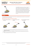
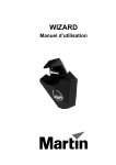
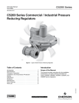
MBV
Modular Ball Valve Interlock
User Manual - Original Language Version
The Castell MBV modular ball valve interlock is an integral valve
interlock designed to enable the locking off, in either the open,
closed or both open and closed conditions. The MBV is suitable
for any quarter-turn valves including Ball, Plug and Butterfly
Valves up to 2 1/2” bore size. Fitting the MBV enforces a logical,
predetermined and safe sequence of operation where the control
of flow paths is critical. The MBV is manufactured in stainless
steel with either brass or stainless steel lock portions, which
makes it ideal for use in harsh or corrosive environments where it
is subject to heavy use.
MBV-FSS-L/O-L/C
Operation
The Castell MBV modular ball valve interlocks are used to prevent unauthorised opening (or closing) of a line ensuring that the
valve is always locked in the crucial position.
MBV modular ball valve interlock, locked closed only condition
1
Valve is normally locked closed,
key is free
2
Insert and turn key to unlock
the valve
3
Valve is unlocked and opened,
key is trapped
1.
The service line is normally closed and the MBV modular ball valve interlock locks the valve in the closed
condition. The key is free.
2.
By inserting and turning the key in the MBV, you can release the valve from being locked closed to open the
line.
3.
The key stays trapped while the valve can be opened.
While every effort has been made to ensure the accuracy of the information provided, no liability can be taken for any errors or omission.
Castell Safety International Limited reserves the right to alter specifications and introduce improvements without prior notice.
www.castell.com
U-MBV-001-E Issue 1
1 of 6
MBV
Modular Ball Valve Interlock
User Manual - Original Language Version
Operation
The Castell MBV
�������������������������������������������������������������������������������������������������������������
modular ball valve interlocks with locked opened and locked closed condition�����������������������������
are used to prevent unauthorised closing of one of lines (e. g. operational line) ensuring that one line is always open (e. g. service line).
MBV modular ball valve interlock, locked opened and locked closed condition
1
Valve is locked opened,
key B is trapped, key A is free
2
Insert and turn key A to unlock
the valve. Turn the valve to
opened position. Turn and
release key B to lock the valve in
the new position.
Valve is closed, key A is trapped,
key B is free
A
A
A
B
3
B
B
1.
The service line is normally open and the MBV modular ball valve interlock locks the valve in the open
position. Key A is free, while key B is trapped.
2.
By inserting and turning key A in the MBV, you can release the valve from locked open condition and change it
to closed. By turning and releasing the key B the valve is locked in the closed condition.
3.
Key A stays trapped and key B is released while the valve locked closed.
While every effort has been made to ensure the accuracy of the information provided, no liability can be taken for any errors or omission.
Castell Safety International Limited reserves the right to alter specifications and introduce improvements without prior notice.
www.castell.com
U-MBV-001-E Issue 1
2 of 6
MBV
Modular Ball Valve Interlock
User Manual - Original Language Version
Usage
The MBV Modular ball valve interlock should be used to prevent unauthorised closing of one of lines ensuring that one line is
always open.
The MBV modular ball valve Interlock is not designed for large bore valves above 2 1/2 inches.
No hazardous substances were used in the manufacture of this product. The product can be disposed of in standard
waste.
Installation
Fitting the MBV enforces a logical, predetermined and safe sequence of operation where the control of flow paths is critical.
The MBV interlocks are available in either the locked open, locked closed or both locked opened and locked closed conditions.
IMPORTANT:
The MBV interlock should only be fitted by the Castell Engineering Team. Please supply the valves to Castell to enable the MBV
to be fitted.
The MBV Modular Ball Valve Interlock must be installed by a competent and qualified person who has read and
understood these instructions. Please retain this document in your technical file.
Maintenance
Periodic visual checks should be carried out by the site manager/safety officer.
Do not lubricate lock barrel with oil or grease, use CK Dry Powder Graphite if necessary.
In case of defects being detected please contact your nearest Castell Support Department for further actions.
Please see Contact section for contact details.
While every effort has been made to ensure the accuracy of the information provided, no liability can be taken for any errors or omission.
Castell Safety International Limited reserves the right to alter specifications and introduce improvements without prior notice.
www.castell.com
U-MBV-001-E Issue 1
3 of 6
MBV
Modular Ball Valve Interlock
User Manual - Original Language Version
Technical Data
Minimum: -40°C [-40°F] ice free for Q & FS type
Temperature rating
Maximum: 107°C [224,6°F] for Q type/140°C [284°F] for FS type or 288°C [550°F] upon
request
Type of mounting
The MBV modular ball valve interlocks must be fitted to the valves by Castell engineering
team
Weight
4,0 kg
Material
Stainless steel with either brass or stainless steel lock portions
MTTF Certification
Available on request
Application
The MBV is designed to operate as part of an integrated safety
system controlling the operation of quarter turn ball valves in safety
critical applications. The typical application of the MBV modular ball
valve interlock is preventing unauthorised closing of one of the lines
ensuring that one line is always open.
Interlock valves in both open and closed positions have an interchangeable key between the valves ensuring that the first valve
is open before the second is closed. While the operational line is
locked opened, the service line is locked closed. Prior to opening
the service line it needs to be ensured the operational line is locked
closed. By inserting key A (from control room) in the MBV, which
controls the operational line, you can unlock the valve and bring it
from opened to closed. By turning and releasing key B, you can
Service line
(normally open)
Operational line
(normally closed)
Key A
MB
V
Locked open
symbol (A)
V
MB
Key B
Locked closed
symbol (B)
MB
V
V
MB
Locked closed
symbol (B)
Key C
Locked open
symbol (C)
lock the valve in the closed condition.
Key B can be taken to the next valve, which controls the service
line. This valve can now be unlocked by inserting and turning key
B in the MBV. The valve position can then be changed from closed
MBV KIT
to open and locked in the opened position by releasing key C. This
MBV KIT
key can then be taken to the control room.
EC-Declaration
We, the manufacturers, declare that the components, detailed herein and placed on the market, comply with all the essential
health and safety requirements applying to them.
Empowered signatory:
Mr T.C. Whelan
Managing Director
While every effort has been made to ensure the accuracy of the information provided, no liability can be taken for any errors or omission.
Castell Safety International Limited reserves the right to alter specifications and introduce improvements without prior notice.
www.castell.com
U-MBV-001-E Issue 1
4 of 6
MBV
Modular Ball Valve Interlock
User Manual - Original Language Version
Drawing
Dimensions:
Note: For safe mounting, use security screws
in mm
MBV, opened position
MBV, closed position
While every effort has been made to ensure the accuracy of the information provided, no liability can be taken for any errors or omission.
Castell Safety International Limited reserves the right to alter specifications and introduce improvements without prior notice.
www.castell.com
U-MBV-001-E Issue 1
5 of 6
MBV
Modular Ball Valve Interlock
User Manual - Original Language Version
Order Information
Product Type
1
Part Number
MBV
-
Example
MBV
-
2
3
4*
FS
S
-
L/O - L/C
-
L/O Symbol
A
5
L/C Symbol
B
1
Lock portion type
FS (1) / Q (1)
2
Material
3
Valve locked state
S = Stainless steel (standard)
L/O = locked open
L/C = locked closed
L/O-L/C = locked open and closed
4*
Optional: additional features available
EEXDSW = complete with ATEX LIMIT SWITCH
SWITCH = complete with ROLER MICRO SWITCH
5
Lock portion symbols
L/O Symbol = locked open symbol (please advise)
L/C Symbol = locked closed symbol (please advise)
FS (1) up to 3 characters / Q (1) up to 6 characters
(1)
FS - Lock type
Q - Lock type
Up to 3 characters Up to 6 characters
Special construction available upon enquiry
Accessories
Product
Part number
Flip Cap
FLIP-S
Contact Information
Castell Safety International
The Castell Building
217 Kingsbury Road
London, NW9 9PQ
England
Castell Safety International
German Office
Oskar-Jäger-Straße 137
50825 Köln
Germany
Castell Interlocks Inc.
Suite 800
150 N Michigan Avenue
Chicago IL 60601
USA
Castell Safety International
Building 1, No. 123
Lane 1165 Jindu Rd
Shanghai, 201108
China
Castell Safety International
No.14, 7th Street, R.E. Nagar
Porur, Chennai - 600116
Tamil Nadu
India
t: +44 (0)20 8200 1200
f: +44 (0)20 8205 0055
[email protected]
t: +49 (0)221 169 47 94
f: +49 (0)221 169 47 95
[email protected]
t: +1.312.360.1516
f: +1.312.268.5174
[email protected]
t: +86 21 5206 8686
f: +86 21 e5206 8191
[email protected]
t: +91 (0)98406 31258
f: +44 (0)20 8205 0055
[email protected]
While every effort has been made to ensure the accuracy of the information provided, no liability can be taken for any errors or omission.
Castell Safety International Limited reserves the right to alter specifications and introduce improvements without prior notice.
www.castell.com
U-MBV-001-E Issue 1
6 of 6