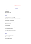
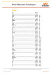
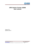
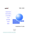
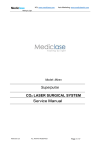
1
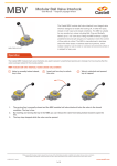
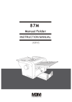
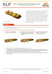
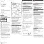
MBV Modular Ball Valve Interlock User Manual - Original Language Version The Castell MBV modular ball valve interlock is an integral valve interlock designed to enable locking off, in either the open, closed or both open and closed conditions. The MBV is suitable for any quarter-turn valves including Ball, Plug and Butterfly Valves up to 2 1/2” bore size. Fitting the MBV enforces a logical, predetermined and safe sequence of operation where the control of flow paths is critical. The MBV is manufactured in stainless steel with stainless steel lock portions, which makes it ideal for use in harsh or corrosive environments where it is subject to heavy use. MBV-FSS-L/O-L/C Operation The Castell MBV modular ball valve interlocks are used to prevent unauthorised opening (or closing) of a line ensuring that the valve is always locked in the crucial position. MBV modular ball valve interlock, locked closed only condition 1 Valve is normally locked closed, key is free 2 Insert and turn key to unlock the valve 3 Valve is unlocked and opened, key is trapped 1. The service line is normally closed and the MBV modular ball valve interlock locks the valve in the closed condition. The key is free. 2. By inserting and turning the key in the MBV, you can release the valve from being locked closed to open the line. 3. The key stays trapped while the valve can be opened. While every effort has been made to ensure the accuracy of the information provided, no liability can be taken for any errors or omission. Castell Safety International Limited reserves the right to alter specifications and introduce improvements without prior notice. www.castell.com U-MBV-001-E Issue 2 1 of 8 MBV Modular Ball Valve Interlock User Manual - Original Language Version Operation The Castell MBV modular ball valve interlocks with locked opened and locked closed condition are used to prevent unauthorised closing of one of lines (e. g. operational line) ensuring that one line is always open (e. g. service line). MBV modular ball valve interlock, locked opened and locked closed condition 1 Valve is locked open, key B is trapped, key A is free 2 Insert and turn key A to unlock the valve. Turn the valve to closed position. Turn and release key B to lock the valve in the new position. Valve is closed, key A is trapped, key B is free A A A B 3 B B 1. The service line is normally open and the MBV modular ball valve interlock locks the valve in the open position. Key A is free, while key B is trapped. 2. By inserting and turning key A in the MBV, the valve can be released from locked open condition and changed to closed. By turning and releasing the key B the valve is locked in the closed condition. 3. Key A stays trapped and key B is released while the valve locked closed. While every effort has been made to ensure the accuracy of the information provided, no liability can be taken for any errors or omission. Castell Safety International Limited reserves the right to alter specifications and introduce improvements without prior notice. www.castell.com U-MBV-001-E Issue 2 2 of 8 MBV Modular Ball Valve Interlock User Manual - Original Language Version Usage The MBV Modular ball valve interlock should be used to prevent unauthorised closing or opening of of lines . The MBV modular ball valve Interlock is not designed for large bore valves above 2 1/2 inches. No hazardous substances were used in the manufacture of this product. The product can be disposed of in standard waste. Installation Fitting the MBV enforces a logical, predetermined and safe sequence of operation where the control of flow paths is critical. The MBV interlocks are available in either the locked open, locked closed or both locked opened and locked closed conditions. IMPORTANT: The MBV interlock should only be fitted by the Castell Engineering Team. Please supply the valves to Castell to enable the MBV to be fitted. The MBV Modular Ball Valve Interlock must be installed by a competent and qualified person who has read and understood these instructions. Please retain this document in your technical file. Maintenance Periodic visual checks should be carried out by the site manager/safety officer. Do not lubricate lock barrel with oil or grease, use CK Dry Powder Graphite if necessary. In case of defects being detected please contact your nearest Castell Support Department for further actions. Please see Contact section for contact details. While every effort has been made to ensure the accuracy of the information provided, no liability can be taken for any errors or omission. Castell Safety International Limited reserves the right to alter specifications and introduce improvements without prior notice. www.castell.com U-MBV-001-E Issue 2 3 of 8 MBV Modular Ball Valve Interlock User Manual - Original Language Version Technical Data Minimum: -40°C [-40°F] ice free for Q & FS type Temperature rating Maximum: 107°C [224,6°F] for Q type/140°C [284°F] for FS type or 288°C [550°F] upon request Type of mounting The MBV modular ball valve interlocks must be fitted to the valves by Castell engineering team Weight 4,0 kg Material Stainless steel body with stainless steel lock portions MTTF Certification Available on request Application The MBV is designed to operate as part of an integrated safety system controlling the operation of quarter turn ball valves in safety critical applications. The typical application of the MBV modular ball valve interlock is preventing unauthorised closing of one of the lines ensuring that one line is always open. Interlock valves in both open and closed positions have an interchangeable key between the valves ensuring that the first valve is open before the second is closed. While the operational line is locked opened, the service line is locked closed. Prior to opening the service line it needs to be ensured the operational line is locked closed. By inserting key A (from control room) in the MBV, which controls the operational line, you can unlock the valve and bring it from opened to closed. By turning and releasing key B, you can Service line (normally open) Operational line (normally closed) Key A MB V Locked open symbol (A) V MB Key B Locked closed symbol (B) MB V V MB Locked closed symbol (B) Key C Locked open symbol (C) lock the valve in the closed condition. Key B can be taken to the next valve, which controls the service line. This valve can now be unlocked by inserting and turning key B in the MBV. The valve position can then be changed from closed MBV KIT to open and locked in the opened position by releasing key C. This MBV KIT key can then be taken to the control room. EC-Declaration We, the manufacturers, declare that the components, detailed herein and placed on the market, comply with all the essential health and safety requirements applying to them. Empowered signatory: Mr T.C. Whelan Managing Director While every effort has been made to ensure the accuracy of the information provided, no liability can be taken for any errors or omission. Castell Safety International Limited reserves the right to alter specifications and introduce improvements without prior notice. www.castell.com U-MBV-001-E Issue 2 4 of 8 MBV Modular Ball Valve Interlock User Manual - Original Language Version Drawing Dimensions: Note: For safe mounting, use security screws in mm MBV, opened position MBV, closed position While every effort has been made to ensure the accuracy of the information provided, no liability can be taken for any errors or omission. Castell Safety International Limited reserves the right to alter specifications and introduce improvements without prior notice. www.castell.com U-MBV-001-E Issue 2 5 of 8 MBV Modular Ball Valve Interlock User Manual - Original Language Version Order Information Product Type 1 Part Number MBV - Example MBV - 2 3 4* FS S - L/O - L/C - L/O Symbol A 5 L/C Symbol B 1 Lock portion type FS (1) / Q (1) 2 Material 3 Valve locked state S = Stainless steel (standard) L/O = locked open L/C = locked closed L/O-L/C = locked open and closed 4* Optional: additional features available SWITCH = complete with LIMIT SWITCH EEXDSW = complete with ATEX LIMIT SWITCH 5 Lock portion symbols L/O Symbol = locked open symbol (please advise) L/C Symbol = locked closed symbol (please advise) FS (1) up to 3 characters / Q (1) up to 6 characters (1) FS - Lock type Q - Lock type Up to 3 characters Up to 6 characters Special construction available upon enquiry Accessories Product Part number Flip Cap FLIP-S Contact Information Castell Safety International The Castell Building 217 Kingsbury Road London, NW9 9PQ UK Castell Safety International Oskar-Jäger-Straße 137 50825 Köln Germany Castell Interlocks 150 N Michigan Avenue Suite 800 Chicago IL 60601 USA Castell Safety International Building 1, No. 123 Lane 1165 Jindu Rd Shanghai, 201108 China Castell Safety International No.14, 7th Street, R.E. Nagar Porur, Chennai - 600116 Tamil Nadu India t: +44 (0)20 8200 1200 f: +44 (0)20 8205 0055 [email protected] t: +49 (0)221 169 47 94 f: +49 (0)221 169 47 95 [email protected] t: +1 (312) 360 1516 f: +1 (312) 268 5174 [email protected] t: +86 (0)21 6151 9028 f: +86 (0)21 6151 9030 [email protected] t: +91 (0)98406 31258 f: +44 (0)20 8205 0055 [email protected] While every effort has been made to ensure the accuracy of the information provided, no liability can be taken for any errors or omission. Castell Safety International Limited reserves the right to alter specifications and introduce improvements without prior notice. www.castell.com U-MBV-001-E Issue 2 6 of 8 MBV Modular Ball Valve Interlock User Manual - Original Language Version Appendix - Pricing Application Form Questionaire In order to ensure accurate and consistent pricing, Castell prices all valves on a price on application basis. Please complete the questions below and return via email to [email protected]. If you require assistance please call our technical sales team at +44 (0)20 8200 1200. Customer organisation name Delivery address Customer organisation contact person Customer organisation contact number and email address Valve details (1) Type of host valve/s (please circle one) Ball Valve (9) Pressure handling capacity (alternatively, please provide a data sheet of valve in selection) Butterfly (2) Valve model, manufacturers and part number (10) Operating temperature (11) Weight of the valve (3) Is it 2 or 3 way valve? (please circle one) 2-way 3-way (12) Is the interlocked valve a sequence or one-off? (please circle one) Sequence One-off (4) Degree of rotation (please circle one) 90 Degrees 180 Degrees (13) Operating cycle of the valve (please circle one) (5) Size of valve in DN or inches Daily Monthly Yearly Other (14) Does the valve handle gases or fluids? (6) Operating torque (15) Is the valve exposed to hazardous operating environment? If so, please specify (7) Class of valve (8) Gland size Note: All completed pricing application forms must be accompanied by a top work drawing of the entity in question. An example of the type of top work drawing required is included on page 8 of this document. While every effort has been made to ensure the accuracy of the information provided, no liability can be taken for any errors or omission. Castell Safety International Limited reserves the right to alter specifications and introduce improvements without prior notice. www.castell.com U-MBV-001-E Issue 2 7 of 8 U-MBV-001-E Issue 2 8 of 8 K J 'ØG' 'X' 'A','B','C','D','E','F','G' 'X', & 'Y' PROVIDE FOLLOWING DIMENSIONS INFORMATION REQUIRED FOR 2 WAY OR 3 WAY VALVE Valve manufacture name Valve Size Valve Type Valve Class Valve No of ways i.e. 2 or 3 What is valve shaft orientation Is it 90° to flow ? or Is it 45° to flow See below RHS diagram example 1 & 2 K2 'E' J FLOW DIM 'L'=LENGTH OF HANDLE 9 K2 J L K1 F G X Y H A B C D E 6 1 2 3 4 5 INFOMATIONS TO BE ADVISED BY CUSTOMER 1 2 3 4 5 6 13 3 WAY VALVE-ADVICE DIRECTION OF FLOW WHEN VALVE IS CLOSED 9 2 WAY VALVE 8 7 FLOW N/A 2 8 DATE 17/08/2012 ECN ISSUE 9 npatel npatel 12 A WIDTH OF FLANGE 'ØG' 'ØH' 'J' 0 FLOW `0.22 `0~ 30' 12 VIEW ON TOP VALVE 13 FLOW TEL; 020-8200-1200 FAX; 020-8205-0055 1st Angle Drawn Date Scale 14 1:1 17/04/2008 npatel Issue 15 PDS02953 2 ML No Third Party, either wholly or in part without the consent, in writing, of Castell Safety International Ltd, London. C B K J I H G F E D Castell Safety International Ltd 217 Kingsbury Road London NW9 9PQ http://www.castell.com of this drawing is reserved by Castell Safety International Ltd.Deletion of Disclosure 1972ItCopyright is issued on condition that it is not copied, reproduced or disclosed toClause a Authorized by; TYPICAL VALVE DIMENSION REQUIREMENT FOR MBV KIT SURFACE UNLESS OTHERWISE STATED TEXTURE;TO BE Ra 1.6um, REF; BS 1134 11 REF; STANDARD BS 8888:2002 DO NOT SCALE IF IN DOUBT-ASK! ANGULAR GENERAL VALVE SHAFT @ 45° TO FLOW EXAMPLE 2 SEE ITEM 6 Denotes Safety Critical Dimension VIEW ON TOP OF VALVE 90 VALVE SHAFT @ 90° TO FLOW EXAMPLE 1 SEE ITEM 6 PLEASE SPECIFY IF VALVE SHAFT IS AT 45° TO FLOW OR VALVE SHAFT IS AT 90° TO FLOW SEE EXAMPLE BELOW DIMENSION FROM CENTRELINE TO FLANGE ON LHS DIMENSION FROM CENTRELINE TO FLANGE ON RHS P.C.D. OF 4 OFF TAPPED HOLES IN VALVE TOP FACE DIAMETER OF VALVE FLANGE OR BODY 'E' 'F' 'K1' 'K2' DEPTH OF TAPPED HOLE 'F' IN TOP FACE OF VALVE 'USABLE HEIGHT OF VALVE SHAFT TAPPED HOLES SIZE 'D' DIMENSION FROM CENTERLINE TO TOP VALVE TOP FACE WHERE TAPPED HOLES(F) MAY BE PROVIDED 'C' DIMENSION FROM CENTERLINE TO TOP OF VALVE SHAFT 15 DIMENSION FROM CENTERLINE TO TOP OF LOCKNUT OF VALVE SHAFT 14 'A' 13 'B' DIMENSION DIAMETER OF VALVE SHAFT ACROSS THE FLAT DIMENSION OF VALVE SHAFT 11 'X' 'Y' KEY UNLESS OTHERWISE SPEC. MATERIAL; SEE DRAWING TOLERANCE TO BE: FINISH; SEE DRAWING METRIC 10 CHECKED APPROVED 3 WAY VALVE VIEW ON TOP OF VALVE VALVE SHOWN CLOSED FLOW 3 WAY VALVE FLOW FLOW 10 3 WAY VALVE VIEW ON TOP OF VALVE VALVE SHOWN OPEN 3 WAY VALVE VALVE SHOWN IN OPEN POSITION VALVE SHAFT SHOWN @ 90° TO FLOW 11 SPECIFY TYPE OF PORT OF 3 WAY VALVE FITTED WITH T PORT OR 'L' PORT? 12 3 WAY VALVE-ADVICE DIRECTION OF FLOW WHEN VALVE IS OPEN 7 2 WAY VALVE 10 SPECIFY HANDLE ROTATION TO CLOSE VALVE IS IT 90° C/W OR IS IT 180° C/W PROVIDE ADDITIONAL DIM. ØH.J.K1 & K2 IF THERE ARE NO TAPPED HOLES 'F' ON VALVE TOP FACE IN BOX ON RHS CL CL 'C' 6 L=lengthof handle 'A' TAPPED HOLE 'F' P.C.D. VIEW ON TOP OF VALVE K1 CL 8 7 6 1 2 3 4 5 CL 2 WAY VALVE FLOW J 'ØH' 5 450 I H G F E D C B VALVE SHAFT VALVE TOP FACE 4 'B' 3 VALVE FLANGE 2 'D' 'Y' A 1 MBV Modular Ball Valve Interlock User Manual - Original Language Version Pricing Application Form Questionaire As to be provided with the Pricing Application Form Top Work Drawing Example While every effort has been made to ensure the accuracy of the information provided, no liability can be taken for any errors or omission. www.castell.com