1
CD-KP
USER’S MANUAL
Rev. 01/2008
remote Key Pad
3000M / 3200 Series
CD Automation S.r.l.
Via Picasso 34/36 - 20025 – Legnano (MI) – ITALY
Tel +39 0331 577479 – Fax +39 0331 579479
E-Mail: [email protected] - WEB: www.cdautomation.com
CD Automation srl
CD-KP 3000M / 3200 Series
User’s Manual
Important warning for safety
This unit is integral part of panel instruments used for equipments of industrial systems.
When there is a possibility that the abnormality of this instrument may cause a major accident or
damage to other instruments, externally install an adequate emergency stop circuit or a protection
circuit to prevent accidents.
Don't use these unit in aerospace applications and / or nuclear.
Important warnings (Avvertenze importanti, attention)
During the operations with units under tension, local regulations regarding electrical installation should
be rigidly observed:
•
Respect the internal safety rules.
•
Don't bend components to maintain insulation distances.
•
Protect the units from high temperature humidity and vibrations.
•
Don't touch components to prevent electrostatic discharges on them.
•
Verify that the order code is in line with real needs.
•
Turn off the power before attaching/detaching the unit. Otherwise electric shock, malfunction or
failure may result.
This listing does not represent a complete enumeration of all necessary safety cautions.
Protection (Protezione, Protection)
The protection of the CD-KP is conforming to the specific international with IP30 protection rating.
Warranty condition (Garanzia, Conditions de garantie)
CD Automation gives a 12 months warranty to its products.
The warranty is limited to repairing and parts substitution in our factory and does exclude products not
properly used and fuses.
Warranty does not include products with serial numbers deleted. The faulty product should be shipped
to CD Automation at customer’s cost and our Service will evaluate if product is under warranty terms.
Substituted parts remain of CD Automation property.
CD Automation reserves the right to modify the own products and this manual without any advise..
2
CD Automation srl
CD-KP 3000M / 3200 Series
User’s Manual
Overview
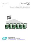
The CD-KP is designed to be connected with all CD Automation's Thyristor units via RS485
communication. On front unit is possible to read the principal operational parameters of the unit like:
power, voltage, current, set-point, alarms, etc.
One of these variables can be selected and re-transmitted via an isolated output (4÷20mA or 0÷10V)
On front unit is also available a plug-in connector RS485 for connect a PC with the Thyristor units
without open the cabinet and without stop the production process.
Technical Specifications
General features:
Material:
PPO self-extinguishing
Mounting:
on panel
Weight
0,3Kg
Voltage range:
From 100 to 130Vac or From 210 to 265Vac
Consumption Max:
3VA
Display Type
LED 7seg.
Height characters
13mm, 10mm
Digit
3
Local/Remote Function
Yes
Communication features:
Interface
RS485
Protocol
Modbus
Max address
10
Re-transmission Output features:
0÷10Vdc:
Isolated, Max 10mA
0÷20mA / 4÷20mA:
Isolated, Max 500Ω
3
CD Automation srl
CD-KP 3000M / 3200 Series
User’s Manual
Installation
Before to install, make sure that the unit have not damages.
If the product has a fault, please contact the dealer from which you purchased the product.
Verify that the product is the same thing as ordered.
Environmental installation conditions
Work temperature
0-45°C
Storage temperature
-25°C a 70°C
Installation
Don’t install at direct sun light, where there are
conductive dust, corrosive gas, vibration or water
and also in salty environmental.
Altitude
Up to 1000 meter over sea level. For higher
altitude reduce the nominal current of 2% for each
100m over 1000m.
Humidity
From 5 to 95% without condense and ice
Dimensions and Fixing holes
96mm
92mm
92mm
48mm
45mm
4
CD Automation srl
CD-KP 3000M / 3200 Series
User’s Manual
Wiring instructions
The unit could be susceptible to interferences lost by near equipments or by the power supply, for this
reason in accord to the fundamental practices rules is opportune take some precautions:
•
•
•
•
•
The electronic circuit of the unit must be supplied from a dedicated voltage and not with inductive
or capacitive loads. We recommend the use of a screened transformer.
The coil contactor, the relays and other inductive loads must be equipped with opportune RC filter.
Use shielded bipolar cables for all the input and output signals.
The signal cables must not be near and parallel to the power cables.
Local regulations regarding electrical installation should be rigidly observed.
Cable dimensions
Max cable: 1.5 mm² (14 AWG)
Connection Diagram
L1
L1
L2/N
L2/N
*1
*2
Retransmission Output
3
*
RS485
PG
L/R
F
Note:
•
*¹ A suitable device must ensure that the unit can be electrically isolated from the supply, this
allows the qualified people to work in safety.
•
*² If the Auxiliary Voltage (written on the identification label) is different from Supply Voltage, use
an external transformer as designated
•
*³ See par.“Analog output configuration”
5
CD Automation srl
CD-KP 3000M / 3200 Series
User’s Manual
Part Names and Functions
1
2
4
3
PG
6
F
L/R
8
5
7
1
The Display1 shows the measured values or the name of the parameters.
The Display1 blinks when an alarm is on.
2
The Display2 shows set-point value or the parameters’ values.
The Display2 blinks when you change the values
3
The Display3 shows the address of the connected unit.
The Display3 blinks when the address is wrong or not connected.
4
The PG Connector is used to configure the thyristor unit with the configuration software and
with the programming cable. When the programming cable is on the PG Connector, all the
Displays blinks and the functions are disabled.
5
Key F (Function) is used for scroll the parameters and for saving the modified values.
6
Key L/R (Local / remote) is used for set-point change through the Increase and Decrease
Keys. It is used also for saving the parameters in the configuration menu.
7
Key UP is used for increase the set-point value or the parameter's value.
8
Key DOWN is used for decrease the set-point value or the parameter's value.
6
CD Automation srl
CD-KP 3000M / 3200 Series
User’s Manual
OPERATOR Menu
This menu is active when you turn ON and contains the state of the parameters on the connected unit.
Press the F key for scroll through the parameters and the keys UP or DOWN for change the values of the
R/W parameters.
Parameter: 0
Function:
Display1 Value:
Display2 Value:
Note:
Parameter: Function:
Display1 Value:
Display2 Value:
Note:
Parameter: )
Function:
Display1 Value:
Display2 Value:
Note:
Parameter: C'
Function:
Display1 Value:
Display2 Value:
Note:
Parameter: N
Function:
Display1 Value:
Note:
Parameter: ==+
Function:
Display3 Value:
Note:
Load Voltage (only for unit 3200)
V
R
This parameter read-only shows on the display 1 the Load Voltage.
For a correct value reading is necessary make the Full scale calibration
(see SETUP menu).
On the display 2 is visualized in percentage the actual value of the set-point.
With the L/R key is possible activate the remote control (display 2 flashing) and the
keys UP and DOWN change the set-point value.
Load Current
A
R
This parameter read-only shows on the display 1 the Load Current.
For a correct value reading is necessary make the Full scale calibration
(see SETUP menu).
On the display 2 is visualized in percentage the actual value of the set-point.
With the L/R key is possible activate the remote control (display 2 flashing) and the
keys UP and DOWN change the set-point value.
Load Power (only for unit 3200)
Kw
R
This parameter read-only shows on the display 1 the Load Power.
For a correct value reading is necessary make the Full scale calibration
(see SETUP menu).
On the display 2 is visualized in percentage the actual value of the set-point.
With the L/R key is possible activate the remote control (display 2 flashing) and the
keys UP and DOWN change the set-point value.
Unit Status
R
This parameter read-only give information about the Status of the thyristor unit
connected.
C' = No Alarm
3' = Calibration active
= Current Limit active
3'
= Heat-sink over temperature
/?
= Heater Break Alarm
$
-N+ = SCR short circuit
The display2 shows the address of the associate unit.
If the address on the display2 is the same of the address on the display3, it is
possible to reset the alarms by pressing the keys UP and DOWN together.
State of Conduction
R/W
This parameter shows the State of Conduction of the connected unit.
N"" = OFF Condition (Load IS NOT Powered)
NC = ON Condition (Load IS Powered)
The keys UP and DOWN change the conduction's value. If pressed at the same time,
they activate the calibration procedure.
Address of the connected unit
R/W
This parameter shows the parameters of an other unit, the actual address is
visualized on the display3
Address range 1 ÷ 10 (…, )
The keys UP and DOWN change the address value, the display3 flashing if the
address is wrong or not connected.
7
CD Automation srl
CD-KP 3000M / 3200 Series
User’s Manual
SETUP Menu
To see this menu, it is necessary visualize one of the parameters 0, , ) on the operator menu, and
press at the same time the F and UP keys for 2 seconds.
Then press the F key for scroll through the parameters and UP or DOWN keys for change the values of
the R/W parameters.
To exit of the SETUP menu, press the keys F and UP again or turn OFF and then turn ON the unit.
Parameter: 0
Function:
Calibration:
Note:
Parameter: Function:
Calibration:
Note:
Parameter: =@
Function:
Value:
Note:
Parameter: )
Function:
Calibration:
Note:
Parameter: )=@
Function:
Value:
Note:
Voltage Full Scale (only for unit 3200)
V
R/W
This parameter is used to set the Load voltage full scale.
•
Give maximum output value at the Thyristor unit, the display1 will visualize the
actual voltage value.
•
With the UP or DOWN keys set the new value (display2 flashing).
•
With the L/R key save the new value.
•
The display2 will become fixed and the procedure is completed.
Press F key to stop the procedure without saving.
Current Full Scale
A
R/W
This parameter is used to set the Load current full scale.
•
Give maximum output value at the Thyristor unit, the display1 will visualize the
actual current value.
•
With the UP or DOWN keys set the new value (display2 flashing).
•
With the L/R key save the new value.
•
The display2 will become fixed and the procedure is completed
Press F key to stop the procedure without saving.
Decimal point for Current value
R/W
This parameter is used to set the decimal point for Current value (on display 1).
0 = no decimal point
1 = decimal point on the first digit
2 = decimal point on the second digit
Press L/R key for save the new value, or Press F key to stop the procedure without
saving.
Power Full Scale (only for unit 3200)
Kw
R/W
This parameter is used to set the Load power full scale.
•
Give maximum output value at the Thyristor unit, the display1 will visualize the
actual power value.
•
With the UP or DOWN keys set the new value (display2 flashing).
•
With the L/R key save the new value.
•
The display2 will become fixed and the procedure is completed.
Press F key to stop the procedure without saving.
Decimal point for Power value
R/W
This parameter is used to set the decimal point for power value (on display 1).
0 = no decimal point
1 = decimal point on the first digit
2 = decimal point on the second digit
Press L/R key for save the new value, or Press F key to stop the procedure without
saving.
8
CD Automation srl
CD-KP 3000M / 3200 Series
User’s Manual
Parameter: -,/
Function:
Min/Max:
Note:
Soft Start Time
cycles
This parameter is used to set the Soft Start cycles of the connected unit.
0 ÷ 255 cycles
Changes are set immediately, without confirmation.
R/W
Parameter: "
Function:
Value:
Feed-Back Type (only for unit 3200)
This parameter is used to set the Feed-Back type of the connected unit.
= Voltage Feed-Back
0
= Current Feed-Back
= Power Feed-Back
)
=
Square Voltage Feed-Back
0
Changes are set immediately, without confirmation.
R/W
Note:
Parameter: ==+
Function:
Display3 Value:
Note:
Address of the connected unit
R/W
This parameter shows the parameters of an other unit, the actual address is
visualized on the display3
Address range 1 ÷ 10 (…, )
The keys UP and DOWN change the address value, the display3 flashing if the
address is wrong or not connected.
9
CD Automation srl
CD-KP 3000M / 3200 Series
User’s Manual
CONFIGURATION Menu
To see this menu, it is necessary visualize the ==+ parameter on the operator menu, and press at the
same time the F and L/R keys for 2 seconds.
Then press the F key for scroll through the parameters and UP or DOWN keys for change the values of
the R/W parameters.
To exit of the CONFIGURATION menu, press the keys F and L/R again or turn OFF and then turn ON the
unit.
Parameter: 1=
Function:
Value:
Note:
Baud Rate
R/W
This parameter is used to set the Baud Rate.
. = 2400 Baud
. = 4800 Baud
. = 9600 Baud
. = 19200 Baud
Press L/R key for save the new value, or Press F key to stop the procedure without
saving.
Parameter: )C0
Function:
Value:
Note:
START-UP Address
R/W
This parameter is used to set the start-up address when the unit is turn ON.
Address range 1 ÷ 10 (…, )
Press L/R key for save the new value, or Press F key to stop the procedure without
saving.
Parameter: )0
Function:
START-UP Parameter
R/W
This parameter is used to set the start-up parameter on the OPERATOR menu, when
the unit is turn ON.
Press L/R key for save the new value, or Press F key to stop the procedure without
saving.
Note:
Parameter: 1/
Function:
Value:
Note:
Parameter: *!)/
Function:
Value:
Note:
Parameter: 0C+)
Function:
Value:
Note:
Output Type
R/W
This parameter is used to set the re-transmission output type.
= 0 ÷ 10Vdc
= 0 ÷ 20mA
= 4 ÷ 20mA
To pass from Vdc to mA or from mA to Vdc is necessary a Hardware modification.
(See par. "Analog output configuration").
Re-transmission Type
R/W
This parameter is used to change the variable on the re-transmission output.
"" = no re-transmission
= Voltage re-transmission (only for unit 3200)
0+
= Current re-transmission
+
= Power re-transmission (only for unit 3200)
)+
= set-point re-transmission
++
Press L/R key for save the new value, or Press F key to stop the procedure without
saving.
Re-transmission Address
R/W
This parameter is used to set the unit's address for the re-transmission output.
Address range 0 ÷ 10 (…, )
With 0 value the re-transmission output change with the parameter ==+.
10
CD Automation srl
CD-KP 3000M / 3200 Series
User’s Manual
Analog output configuration
The re-transmission output is already configured in line with customer requirements that are defined in
the Order Code.
However, if you wish to change the re-transmission output type (ex. from 0÷10V to 4÷20mA) proceed
as follows:
Warning: Before connecting or disconnecting the unit check that power are isolated from
voltage sources.
J6
A-B
B-C
Type
0÷10Vdc
0÷20mA / 4÷20mA
J6
A
B
C
Order Code
CODE
C
D
-
K
P
-
_
_
_
_
SERIES
CD1000
CD3000M
CD3200
1
2
3
AUXILIARY VOLTAGE
From 100 to 130Vac
From 210 to 265Vac
1
2
RE-TRANSMISSION
None
0÷10Vdc
0÷20mA
4÷20mA
0
1
2
3
USER’S MANUAL
None
Italian
English
0
1
2
ENG CD-KP 3000M-3200.doc - 01.doc
2