1
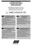
DREXELBROOK
Leader in
Level Measurement
For Assistance Call 1-800-527-6297
Outside North America Call + 215-674-1234
Installation and
Operating Instructions
Series 505-5100
Continuous Ultrasonic Transmitter
using 405-5100 Electronics
Software Version VAL4.85
+ 215-674-1234 Outside North America
1-800-553-9092 US and Canada
www.drexelbrook.com
[email protected]
Need More Instruction Books ?
Go to www.drexelbrook.com
Look under this specific product
Download Instruction Manual
AMETEK Drexelbrook makes no warranty of any kind with regard to the material contained in
this manual, including, but not limited to, implied warranties or fitness for a particular purpose.
Drexelbrook shall not be liable for errors contained herein or for incidental or consequential
damages in connection with the performance or use of material.
Copyright 2002 AMETEK Drexelbrook
EDO#12-02-243
505-5100-LM
Series 505-5100
Continuous Ultrasonic Transmitter
using 405-5100 Electronics
Software Version VAL4.85
DREXELBROOK
An ISO 9001 Certified Company
205 Keith Valley Road Horsham, PA 19044
US Sales
1-800-553-9092
24 Hour Service
1-800-527-6297
International
+ 215-674-1234
Fax
+ 215-674-2731
E-mail
[email protected]
Web
www.drexelbrook.com
EDO#12-02-243
505-5100-LM
Table of Contents
Section 1 - Introduction ................................................................................................ 1
1.1 Product Description ................................................................................................ 1
1.2 Technology ............................................................................................................. 1
1.3 Models Available .................................................................................................... 1
1.4 Key Terms ............................................................................................................... 3
1.5 Types of Output ....................................................................................................... 3
Section 2 - Installation .................................................................................................. 4
2.1 Unpacking ............................................................................................................... 4
2.2 Mounting the Transmitter ........................................................................................ 4
2.3 Wiring the Transmitter ............................................................................................. 8
Section 3 - Operation .................................................................................................. 10
3.1 Indicators and Controls ......................................................................................... 10
3.2 Time Delay and Repetition Rate ........................................................................... 13
3.3 Step Gain Switch .................................................................................................. 14
3.4 High Discrimination Units ..................................................................................... 14
Section 4 - Calibration ................................................................................................ 15
4.1 Introduction ........................................................................................................... 15
4.2 Calibration ............................................................................................................ 15
4.3 Setpoint Calibration .............................................................................................. 18
4.4 Relay Package (Optional) ..................................................................................... 19
Section 5 - Troubleshooting ....................................................................................... 22
5.1 Troubleshooting Procedures ................................................................................. 22
5.2 Factory Assistance................................................................................................ 24
5.3 Field Service ........................................................................................................ 24
5.4 Customer Training ................................................................................................ 24
5.5 Equipment Return ................................................................................................. 25
Section 6 - Specifications ........................................................................................... 26
6.1 Transmitter Specifications..................................................................................... 26
6.2 Transducer Specifications .................................................................................... 27
505-5100 Series Ultrasonic TransmitterTM
SECTION 1
INTRODUCTION
1.1 Product Description
The Drexelbrook Series 505-5100 Liquid Level Transmitter
is an integral assembly which accurately measures continuous
level up to a range of 80 feet, using ultrasonic technology.
The level measurement output is a 4-20 mA Vdcsignal.
The ultrasonic transducer does not contain moving components. It is not affected by electrical or physical parameters and has a wide range of temperature operation. The
sensing element is made of CPVC for compatibility with a
wide range of process materials.
1.2 Technology
Ultrasonic transmitters work on the principle of sending a
pulsed, high-frequency sound wave from a peizo electric
transducer to the contents of the vessel. The device measures the length of time it takes for the reflected sound
wave to return to the transducer. A successful measurement depends on reflection from the process material in a
straight line back to the transducer.
The two basic modes of operation are the “delta level” and
“delta distance.” In the delta level mode, the current output
(4-20 mA dc) increases as the liquid level rises. In the delta
distance mode, the current output increases as the level falls
(distance to the transducer increases). The desired span
range may be set from a minimum of 3 inches up to 80 feet.
To ignore obstructions in the vessel, AutoprofilingTM tank
mapping has been developed, which allows a “sonic snapshot” of an empty vessel. The transducer transmits a sound
burst and the echo is recorded as a signature of the tank.
Any obstructions in the vessel will send an echo and create
a profile. Later on, this signature or profile is locked into
the ultrasonic unit’s memory so it will not respond to echoes
created by these obstructions.
1.3 Models Available
505-51X0-X02-
Continuous Ultrasonic
Transmitter with 4-20 mA
Configuration options:
0 - Integral Electronics
7 - Remote Electronics
Electronic Unit options:
1 - High Discrimination Electronic Unit
2 - Adjustable Gain Electronic Unit
Diagram on following page identifies components.
1
505-5100 Series Ultrasonic TransmitterTM
—Legend
1 Operating Mode Switch
(Time Delay/Rep Rate Control)
see section 3.1
2 Calibration Switches
see sections 3.1 and 4.2
3 Optional Setpoint Switches
see section 4.3
7 Transducer Terminal Strip
see section 2.3
8 24 Vdc Alarm Outputs
see sections 3.1
9 Signal Loop Terminals
see section 2.3
4 Switch 8
see sections 3.1 and 4.2
10 Sink/Source Mode Selector
Jumper Block
see section 2.3
5 Near Zone and Lost Echo LEDs
see sections 2.2 and 3.1
11 Power Terminals
see section 2.3
6 Calibration Pushbutton
and System Reset
see section 3.1
12 Step Gain Switch (not available with
High Discrimination units) see section 3.3
13 Connector to 15 Vdc for optional Relay
Package see section 4.4
2
505-5100 Series Ultrasonic TransmitterTM
1.4 Key Terms
Zero:
The point at which the output is to equal 4 mA
(0% level) measured from the transducer face
down (â).
Span:
The point at which 20 mA (100%) occurs measured from the zero point.
Range: Maximum distance from the transducer face.
1.5 Types of Output
Near
Zone:
The distance just below the transducer face
where the transmitter cannot make a level measurement (30 inches).
Lost
Echo:
A condition that occurs when the acoustic energy
is not being returned to the transducer. Loss of
echo may occur when large amounts of foam are
present.
Level
Mode:
Output increases as level increases. Level mode
output is the most common type of output
measurement.
Distance
Mode: Output decreases as level increases.
Source
Mode:
Transmitter provides 24 Vdc to drive the loop
(standard).
Sink
Mode:
Jumper has been moved to allow the transmitter
to receive 24 Vdc from an external supply.
3
505-5100 Series Ultrasonic TransmitterTM
SECTION 2
INSTALLATION
2.1 Unpacking
Carefully remove the contents of the shipping carton and
check each item against the packing list before destroying any
packing material. If there is any shortage or damage, report
it to the factory immediately.
2.2 Mounting
Transmitter
The 505-5100 Series ultrasonic transmitter is available with
the electronic unit and transducer as either a single integral
assembly or connected by 2 coaxial cables in the remote configuration. Extended sensing element lengths and special
mountings can be provided to fit specific mounting applications. Refer to Figures 2-2 and 2-3 for standard mounting
dimensions.
• The 505-5100 Series transmitter is designed for field
mounting, but it should be mounted in a location as free as
possible from vibration, corrosive atmospheres, and any
possibility of mechanical damage.
• For convenience when adjusting, place the electronic unit in
a reasonably accessible location. Ambient temperature
should be between -40oF and 160oF (-40oC to 70oC).
• The transducer axis must be mounted perpendicular to the
liquid surface.
• Ensure that the transducer face is not recessed into a
mounting nozzle, as stray reflections can cause faulty
operation.
NOTE
NOTICE
If the transducer must be mounted in a nozzle, use a
505-5110 High Discrimination unit.
• When mounting the transducer, consideration must be
given to the 30-inch Near Zone. If the level rises to within
30 inches of the sensing element face, a 4 or 20 mA signal
(20=level mode, 4=distance mode) will be generated; the
Near Zone LED will light; and the Near Zone Alarm Output
will drop from 24 Vdc to 0 Vdc.
• When mounting the transducer, consideration must be
given to the beam angle of the acoustic signal. The
typical conical beam angle of the acoustic signal is 12
degrees (6 degrees from center). Mount the transducer
so that the beam does not hit the tank wall, ladder
rungs, or other obstructions.
4
505-5100 Series Ultrasonic TransmitterTM
2.2 Mounting
Transmitter
(continued)
Application Example
Since the maximum distance that the 505-5100 ultrasonic
transmitter can sense is 80 feet and the acoustic beam
spreads out at a rate of 1.25 inches per foot, the transducer
should be mounted 100 inches from the tank wall.
If it isn’t possible to mount the transducer the required
distance from the tank wall and the acoustic beam does
strike the side wall of the tank, then some acoustic energy
will be lost. If the sidewall is relatively smooth, some signal
loss can be tolerated; but any structure or 90 degree obstructions on the sidewall may be detected. See Figure 2-1.
CAUTION
If the Series 505-5100 is located in a
hazardous environment, do not open
enclosure cover or make/break any
electrical connections without first
disconnecting electrical power at the
source. Ensure that wiring, electrical
fittings and conduit connections conform to electrical codes for specific
location and hazard level.
CORRECT
INCORRECT
CORRECT
DREXELBROOK
DREXELBROOK
DREXELBROOK
5
5
5
INCORRECT
DREXELBROOK
5
FILL
LINE
DREXELBROOK
DREXELBROOK
5
5
DREXELBROOK
TANK
STRUCTURE
ECHO STRONGER
THAN LEVEL
5
TOO
MUCH
LOST
ENERGY
LOST
ENERGY
6o
STRONG
WEAK
TOO CLOSE
TO WALL
OK
BEAM ANGLE
Figure 2-1
Mounting Recommendations
5
6o
505-5100 Series Ultrasonic TransmitterTM
Figure 2-2
505-5100 Series Mounting Dimensions
Integral Mounting
6
505-5100 Series Ultrasonic TransmitterTM
Figure 2-3
505-5100 Series Mounting Dimensions
Remote Mounting
7
505-5100 Series Ultrasonic TransmitterTM
2.3 Wiring Transmitter
Refer to Figures 2-4 through 2-6 for the wiring diagrams of
the 505-5100 transmitters. Connect input power and
output leads to terminal block (TB1) as shown. The 5055100 is shipped with the Output Select jumper block set to
source (the unit will supply all power to the signal loop.) If
an external power supply is used, jumper should be moved
to sink position. Section 3 - Operation describes the other
indicators and controls.
For integral transmitters, the level measuring cable and
temperature compensation wires are prewired. Figure 2-6
shows the customer wiring of the level and temperature
cables for remote-mounted units.
Figure 2-4
Output Select Jumper Block and Input Power Terminal Block (TB1)
120/240 Vac Unit
8
505-5100 Series Ultrasonic TransmitterTM
Figure 2-5
Output Select Jumper Block and Input Power Terminal Block (TB1)
24 Vdc Unit
Figure 2-6
Sensing Element Wiring Connections, Remote Transmitter
9
505-5100 Series Ultrasonic TransmitterTM
SECTION 3
OPERATION
Refer to Figure 3-1 for the location of indicators and
controls.
3.1 Indicators & Controls
—SW8 Level/Distance Mode Selection
Lost Echo Fault Output Selection
The selection of either level or distance mode is accomplished by changing switch position 4 on SW8. Level and
distance modes are explained in Section 1.4.
• When SW8-4 is switched down (OPEN), the transmitter operates in level mode.
• When SW8-4 is switched up (ON), the transmitter
operates in distance mode.
Switch position 2 of SW8 is used to set the lost echo fault
output.
• When SW8-2 is in switched down (OPEN), the transmitter will produce 4 mA output during a lost echo
condition.
• When SW8-2 is switched up (ON), the transmitter
will produce 20 mA output during a lost echo
condition.
Application requires
Overfill Prevention
(no spills)
Application requires
Low Level Prevention
(pump will not run dry)
Material cannot go
over high point
Material cannot go
below low point
Lost Echo
typically set 20 mA
Lost Echo
typically set 4 mA
—Time Delay/Rep Rate Control
The time delay/repetition rate control is located above
SW8. The time delay can be set to 0,15, or 45 seconds and
the repetition rate (time between ultrasonic pulse transmissions) can be set to 140, 280, or 420 milliseconds.
• A 0-second time delay and 140 millisecond repetition
rate (position 0) is the factory-set default.
• A 280 millisecond repetition rate is used for domed-top
tanks.
• Consult factory to use a 420 millisecond repetition rate.
Refer to Section 3.2 for more details.
10
505-5100 Series Ultrasonic TransmitterTM
3.1 Indicators & Controls —Zero and Span Calibration Switches
(continued)
The zero and span are each set using three, ten-position
rotary switches. Zero and span settings are made in inches
with 1-inch resolution. Zero and span switches are used to
calibrate the unit, discussed in Section 4.2.
—LED Indicators
Two LED indicators are located on the transmitter to alert the
user to a near zone or lost echo condition or improper calibration.
—Calibration Pushbutton
The calibration pushbutton is used in conjunction with SW8
for maximum calibration accuracy. This button can also be
used as a system reset.
—Alarm Relays
Outputs (24 volts @ 35 mA) for near zone, lost echo and 2
alarm setpoints are provided to activate external relays or
alarms. These are separate relay packages purchased as an
option.
—Step Gain Switch
Changes the gain of the ultrasonic transmitter to lessen any
effect due to noise or obstruction. (Not available on High
Discrimination chassis.)
11
505-5100 Series Ultrasonic TransmitterTM
Figure 3-1
Indicators and Controls
12
505-5100 Series Ultrasonic TransmitterTM
3.2 Time Delay and
Repetition Rate
Certain applications may require a change of repetition rate
and time delay.
• Increasing time delay to either 15 or 45 seconds will
smooth out a jumpy output signal caused by wave action
or turbulence in the tank.
• Changing the repetition rate is required any time that
the tank roof is curved. A longer repetition rate ensures
that the transmitter is not affected by reflected sound
waves from the curved roof.
• A lengthened repetition rate also helps reduce loss of
echo due to foam.
If your application is similar to one described above, change
the time delay or repetition rate using a small screwdriver
and switch SW4. Table 3-1 details the switch settings. Each
setting controls both time delay and repetition rate.
Table 3-1
Time Delay and Repetition Rate
Switch (SW4) Settings
Switch
Position
Time
Delay
0
1
2
3
4
5
6-9
A-F
0 seconds
15 seconds
45 seconds
0 seconds
15 seconds
45 seconds
not used
not used
Repetition
Rate
280 msec
280 msec
280 msec
420 msec
420 msec
420 msec
not used
not used
A step gain switch is available on standard 505-5100 units.
The step gain switch can be used to decrease the acoustic
signal and avoid noise interference.
For example, the standard chassis is capable of shooting to a
distance of 80 feet. The extra power produced to shoot the 80foot signal might be too much and could possibly cause nuisance reflections from irregular sidewalls, tank obstructions,
or agitator blades. By reducing the gain of the chassis using
the step gain switch, the effect of nuisance reflections can be
eliminated.
13
505-5100 Series Ultrasonic TransmitterTM
3.3 Step Gain Switch
The factory setting is position 6.
This setting should be adequate for most applications.
If false high readings occur, decrease the gain.
Step Gain Switch
6
5
4
3
2
1
3.4 High Discrimination Units
100% gain
80 % gain
67% gain
50% gain
40% gain
30% gain
20% gain
High discrimination chassis (405-5110) contains an
additional circuit that automatically reduces the effect
of nuisance echos created when mounting the transducer
in a nozzle. This circuit allows mounting the transducer
inside a pipe up to 14 inches above the tank opening.
Also, the high discrimination circuit lessens any effect
from agitator blades and/or small obstructions and
reduces interference caused by electrical noise.
The high discrimination electronics unit should not be
used in applications where foam is present.
14
505-5100 Series Ultrasonic TransmitterTM
SECTION 4
CALIBRATION
4.1 Introduction
The 505-5100 Series transmitters are set at the factory to
operate, in most applications, with minimal calibration. However, it is still necessary to set the Zero and Span switches for
your actual vessel. This procedure is outlined in Section 4.2.
Once this procedure is accomplished the level reading should
be within approximately 1% accuracy of range.
Use this procedure to set the Zero and Span for the vessel.
Choose Level or Distance mode:
4.2 Calibration
—Level Mode
With the power off, verify that all four switches on SW8 are
DOWN (open). Refer to Figure 4-1.
Set the Zero calibration switches to equal the distance in
inches from the transducer face down to the minimum level
(usually tank bottom–0% or 4 mA). Refer to the calibration
example in Figure 4-2. For this example, the switches are set
to 1-8-6 starting with the top switch.
Set the Span calibration switches to equal the distance in
inches from the minimum level to the maximum level—
100% point or 20 mA (e.g. 1-5-6 starting with top switch).
Span setting must be at least 30 inches less than zero
setting
—Distance Mode
With the power off, verify SW8 is configured properly.
Switches 1-3 are DOWN (open) and switch 4 is UP (on).
See Figure 3-1.
Set the Zero calibration switches to equal the distance in
inches from the sensing element face to the maximum level
(0% or 4 mA). Refer to the calibration example in Figure 4-2.
For this example, the switches are set to 0-3-0 starting with
the top switch. Zero switches must not be set lower than
0-3-0.
Set the Span calibration switches to equal the distance in
inches from the maximum level to the minimum level—
100% or 20 mA (e.g. 1-5-6 starting with the top switch).
NOTICE
NOTE
The maximum level point must be at least 30 inches
from the sensing element (near zone).
Apply power; the 4-20 mA should now represent the amount of
material in the vessel to within approximately 1%.
15
505-5100 Series Ultrasonic TransmitterTM
4.2 Calibration
(continued)
Figure 4-1
Calibration and Alarm Switches
NOTICE
NOTE
If, after calibration, the unit is not reading within 3% of
actual level, call Factory Service at 1-800-527-6297.
16
505-5100 Series Ultrasonic TransmitterTM
Level Mode
Distance Mode
Figure 4-2
Calibration Example
17
505-5100 Series Ultrasonic TransmitterTM
4.3 Setpoint Calibration
(only for those
units equipped
with optional 24
Vdc outputs)
a. Refer to Figure 4-1 for location of alarm switches
(ALM1 and ALM2).
b. Alarm points are set directly in inches from the zero
point.
Normally, 24 Vdc is present on the male pins J4-J7,
measured from the pins to common. When a setpoint
alarm is exceeded, the voltage drops to 0 Vdc.
In the calibration example of Figure 4-2, the low alarm
point would be set 6 inches from the zero point or
minimum level. Starting with the top switch of ALM1,
the settings would be 0-0-6. The high alarm point is 6
inches from the maximum level, which is 156 inches in
this example. Starting with the top switch of ALM2,
the settings would be 1-5-0 (span — 6 inches).
c. Alarm settings ALM1 and ALM2 can be set to alarm
at any point in the calibrated range.
d. Connections are made to the transmitter using female
connectors to J4, J5, J6, J7 and common connection, as
shown in Figure 4-3.
Figure 4-3
Alarm Relay Connections (J6 and J7)
18
505-5100 Series Ultrasonic TransmitterTM
4.4 Relay Package
(Optional)
As an option, a 401-600 external relay package is available.
This package can provide remote-mounted relay outputs for
Alarm 1, Alarm 2, Lost Echo and Near Zone. This package
can also be equipped with remote LEDs to indicate Loss of
Echo or Near Zone.
A short cable (Figure 4-4) is available to connect the 401-600
to the ultrasonic chassis. Cable 380-5000-053 contains 36
inches of ribbon cable with 5 colored crimp connectors (labelled 2 through 6 on Figure 4-4) and 1 non-crimped connector (labelled 1 on Figure 4-4). The non-crimped connector is
only required if using a relay package that contains remote
LEDs for indicating Lost Echo or Near Zone.
Figure 4-4
Cable to Optional Relay Package
19
505-5100 Series Ultrasonic TransmitterTM
Figure 4-5
Optional Relay Package, Wiring
20
505-5100 Series Ultrasonic TransmitterTM
Figure 4-6
Optional Relay Package
System Configuration and Mounting Dimensions
21
505-5100 Series Ultrasonic TransmitterTM
SECTION 5
TROUBLESHOOTING
The 505-5100 Transmitter is designed to give years of
unattended service. No periodic or scheduled maintenance
is required.
5.1 Troubleshooting
Procedures
If a problem should occur with the operation of the transmitter, use the following procedure for troubleshooting.
a. Ensure wiring connections are correct.
b. If the liquid surface has severe turbulence in the area
where the ultrasonic beam hits, consider setting SW4
to add 15 or 45 seconds damping to 4-20mA loop.
c. Any continuous ultrasonic transmitter signal/echo can
be adversely affected by significant foam on the liquid
level surface. If this condition exists, please consult the
factory for further application review and advice.
d. Ensure that the transducer face is not recessed into a
mounting nozzle, unless High Discrimination
electronics are used. Spurious reflections from the
nozzle openings into the vessel can cause faulty
operation.
e. If attempts to locate the difficulty fail, notify the local
factory representative, or call the factory toll-free at
1-800-527-6297. To aid in troubleshooting, please
complete the information on Table 5-1 before calling
the factory service department.
22
505-5100 Series Ultrasonic TransmitterTM
Table 5-1
ULTRASONIC PHONE TROUBLESHOOTING
Transmitter Model Number __________________Serial Number____________________
Process Material_________________Temperature_______________Pressure_____________
What is the Loop Current? ____________
Is it stable?________________
Test the ability of the electronic unit to produce 4 and 20 mA. Place switch 3 of SW8 to
the ON position (up). Now by alternating switch 2, ON (up) position should =4 mA. OFF
(down) position should =20 mA.
Are either of the 2 red LEDs illuminated? ________ (if yes, which one?)_______________
Check for correct voltage on TB1 (see Figure 2-4). ___________
Loop supply voltage is measured at TB2 (with no load) should be 24-30 Vdc in source
mode.
What is the position of the hex switch SW4 (factory setting is zero)? (See Figure 3-1.)
What is the position of the step gain switch (factory setting is 6)? (See Figure 2-5.)
What are the switch positions of SW8? (See Figure 3-1).
(All should be DOWN (off) with the exception of position 4—it can be either UP (on) or
DOWN (off).
SW8
List the positions of the Span and Zero rotary calibration switches (Figure 3-1.)
SW1, SW2, SW3, SW5, SW6, AND SW7?
SW1____
SW5____
In level mode Zero must always be larger than Span.
SW2____
SW6____
SW3____
SW7____
Transducer Temperature Check:
• Expect to find 0.65 Vdc between brown terminal [BRN] and housing.
• Should be able to measure approximatly 290 µA on digital meter placed in
series with orange lead and its terminal [ORG].
With sensing element disconnected, expect reading of 12K ohm between center wire
terminal [CW] and shield [SHD], using an analog meter..
23
505-5100 Series Ultrasonic TransmitterTM
5.2
Factory Assistance
AMETEK Drexelbrook can answer any questions about your
level measurement system. Call Customer Service at
1-800-553-9092 (US and Canada) , or
+ 215-674-1234 (International).
If you require assistance and attempts to locate the problem
have failed:
• Contact your local Drexelbrook representative,
• Call the Service department toll-free at 1-800-527-6297
(US and Canada) or + 215-674-1234 (International),
• FAX the Service department at + 215-443-5117, or
• E-Mail to [email protected]
Please provide the following information:
Instrument Model Number ___________________________
Sensing Element Model Number and Length ___________
Original Purchase Order Number _____________________
Material being measured _____________________________
Temperature __________________________________
Pressure ______________________________________
Agitation ______________________________________
Brief description of the problem _______________________
____________________________________________________
____________________________________________________
Checkout procedures that have failed __________________
____________________________________________________
____________________________________________________
5.3
Field Service
Trained field servicemen are available on a time-plus-expense
basis to assist in start-ups, diagnosing difficult application
problems, or in-plant training of personnel. Contact the service department for further details.
5.4
Customer Training
Periodically, AMETEK Drexelbrook instrument training seminars for customers are held at the factory. These sessions are
guided by Drexelbrook engineers and specialists, and provide
detailed information on all aspects of level measurement, including theory and practice of instrument operation. For more information about these valuable workshops, write to
AMETEK Drexelbrook, attention:
Communications/ Training Group, or call direct + 215-674-1234.
24
505-5100 Series Ultrasonic TransmitterTM
5.5
Equipment Return
In order to provide the best service, any equipment being
returned for repair or credit must be pre-approved by the
factory.
In many applications, sensing elements are exposed to hazardous materials.
• OSHA mandates that our employees be informed and
protected from hazardous chemicals.
• Material Safety Data Sheets (MSDS) listing the
hazardous materials to which the sensing element has
been exposed MUST accompany any repair.
• It is your responsibility to fully disclose all chemicals and
decontaminate the sensing element.
To obtain a return authorization (RA#), contact the Service
department at 1-800-527-6297 (US and Canada) or
+ 215-674-1234 (International).
Please provide the following information:
Model Number of Return Equipment ____________________
Serial Number _________________________________________
Original Purchase Order Number _______________________
Process Materials that equipment has been exposed
to _____________________________________________________
MSDS sheets for any hazardous materials
Billing Address ________________________________________
______________________________________________________
Shipping Address ______________________________________
______________________________________________________
Purchase Order Number for Repairs _____________________
Please include a purchase order even if the repair is under
warranty. If repair is covered under warranty, you will not be
charged.
Ship equipment freight prepaid to:
AMETEK-DREXELBROOK.
205 KEITH VALLEY ROAD
HORSHAM, PA 19044-1499
COD shipments will not be accepted.
25
505-5100 Series Ultrasonic TransmitterTM
SECTION 6
SPECIFICATIONS
6.1 Transmitter
Specifications
Near/Dead Zone:
30 inches (62 cm)
Minimum Span:
6 inches (15.2 cm) or 10% of
calibrated range (whichever is
greater)
Maximum Span:
80 feet (24.4 m)
2-Wire Signal Loop:
4-20 mA DC (isolated)
source or sink
•Load Voltage:
Source Mode, 24 Vdc output
Sink Mode, 8-60 Vdc input
•Loop Resistance: Source Mode, 0-1000 ohms
(@ 24 Vdc)
Repeatability:
0.10 inch (3mm)
Resolution:
0.30 inch (8mm)
Linearity:
0.2% of full scale for spans less than 3
feet.
Ambient
Temperature:
-40o to 160oF (-40o to 70oC)
Temperature
Compensation:
Automatic
Calibration:
To nearest 1 inch (2.5 cm)
Zero and Span range switches,
ranges are set directly in inches.
Power
Requirement:
120 Vac, 50/60 Hz;
240 Vac, 50/60 Hz;
or 24 Vdc at 250 mA (without
relays)
Power
Consumption:
6 watts @ 120 Vac
Response
Time:
2 seconds (approx.)
26
505-5100 Series Ultrasonic TransmitterTM
6.1 Transmitter
Specifications
Damping:
0,15, or 45 second response time
(field-selectable)
Lost Echo:
LED indication, loop current 4 mA
Additional output: 24 Vdc 35 mA max.
Near Zone:
LED indication, loop current 20 mA
Additional output: 24 Vdc 35 mA max.
Optional
Alarm
Outputs:
2 outputs: 24 Vdc 35 mA maximum
Alarm points are set in inches.
Pulse Repeat
Rate:
280 or 420 mS (field-selectable)
Mounting:
Integral or Remote
4" NPT fitting (flange mounts available)
(continued)
6.2 Transducer
Specifications
Sensing
Element
Material:
CPVC
Beam
Angle:
Conical, 12o typical, 3dB down outside the
cone
Process
Temperature:
-40oF to 160oF(CPVC) (-40oC to 70oC)
Process
Pressure:
-10 to 50 PSIG
27
DREXELBROOK
An ISO 9001 Certified Company
205 Keith Valley Road Horsham, PA 19044
US Sales
1-800-553-9092
24 Hour Service
1-800-527-6297
International
+ 215-674-1234
Fax
+ 215-674-2731
E-mail
[email protected]
Web
www.drexelbrook.com