1
Technical
specification
Xtender serial protocol
Author : Marc Emery
Date
: 08.09.11
Version : V1.3.1
R:\5 Tech\5F Specifications techniques\
Technical specification
Xtender serial protocol
Contents
1. INTRODUCTION ............................................................................................................................................ 2
1.1 CONVENTIONS USED IN THIS DOCUMENT ................................................................................................................. 2
1.2 LIST OF ACRONYMS ............................................................................................................................................. 2
2. PHYSICAL LAYER ........................................................................................................................................... 3
2.1 CONNECTOR PINNING ......................................................................................................................................... 3
2.2 CABLE TO USE .................................................................................................................................................... 3
3. DATA LINK LAYER ......................................................................................................................................... 4
3.1 USART CONFIGURATION ..................................................................................................................................... 4
3.2 BYTE ENDIANNESS .............................................................................................................................................. 4
3.3 FRAME ............................................................................................................................................................. 4
3.4 ADDRESSING THE DEVICES .................................................................................................................................... 5
3.5 RESPONSE DELAY ................................................................................................................................................ 5
4. APPLICATION LAYER ..................................................................................................................................... 6
4.1 SERVICES .......................................................................................................................................................... 6
4.2 OBJECT MODEL .................................................................................................................................................. 6
4.2.1 READ_PROPERTY service ........................................................................................................................ 7
4.2.2 WRITE_PROPERTY service ...................................................................................................................... 8
4.2.3 Format .................................................................................................................................................... 8
4.3 ERROR CODES .................................................................................................................................................... 9
4.4 SYSTEM STATE OBJECTS...................................................................................................................................... 10
4.4.1 Properties ............................................................................................................................................. 10
4.4.2 Available system states on the Xtender Inverter .................................................................................. 10
4.4.3 Available system states on the BSP ...................................................................................................... 12
4.5 PARAMETER OBJECTS ........................................................................................................................................ 13
4.5.1 Properties ............................................................................................................................................. 13
4.5.2 Values of level properties ..................................................................................................................... 13
4.5.3 Available parameters on the Xtender Inverter ..................................................................................... 13
4.5.4 Cyclic write of parameters on the Xtender Inverter ............................................................................. 14
4.5.5 Hours encoding .................................................................................................................................... 14
4.5.6 Days of the week encoding .................................................................................................................. 14
4.5.7 Month of the year encoding ................................................................................................................. 14
4.5.8 Date encoding ...................................................................................................................................... 15
4.5.9 Signal encoding .................................................................................................................................... 15
5. EXAMPLES OF FRAMES ............................................................................................................................... 16
5.1 COMMAND LINE TOOL ....................................................................................................................................... 16
5.2 READ THE VALUE OF A SYSTEM STATE.................................................................................................................... 16
5.3 WRITE THE QSP_VALUE OF A PARAMETER.............................................................................................................. 17
6. ANNEXES .................................................................................................................................................... 18
6.1 XTENDER PARAMETERS ...................................................................................................................................... 18
6.2 BSP PARAMETERS ............................................................................................................................................ 24
6.3 RCC PARAMETERS ............................................................................................................................................ 25
V1.3.1
1 / 25
Technical specification
Xtender serial protocol
1. Introduction
This technical specification describes the protocol used to communicate with the Studer
Innotec Xcom-232i communication module. It is also valid for the discontinuted RCC-02/03 special execution ES N° 32 (RCC-02/-03-32).
1.1 Conventions used in this document
•
Numbers that start with “0x” are in hexadecimal, like in the C integer litterals.
•
constant values are usually represented in UPPER CASE
•
field names are in lower_case_with_underscore
1.2 List of acronyms
V1.3.1
RCC
The Studer Innotec remote control used to configure the Xtender
system
Xcom-232i
The Studer Innotec RS-232 communication module that has the
function of a DCE, Data Communications Equipment
DTE
Data Terminal Equipment, the PC or controller system that wants to
communicate with the Xcom-232i
SCOM
Naming prefix used for the Studer Innotec serial protocol
2 / 25
Technical specification
Xtender serial protocol
2. Physical layer
The physical layer is RS-232. The Xcom-232i is equiped with a DE-9 (also known as DB9) Female connector which provides this interface.
The serial port is galvanically separated with an isolation of 500 V DC relative to the
negative battery potential.
2.1 Connector Pinning
On the female connector of the RCC, only the wires “receive data”, “transmitted data”
and ground are connected. The other wires are not connected, and the DTE must ignore
signals such as CTS, DTR or DCD.
pin number
usage
1
not connected
2
RxD
3
TxD
4
not connected
5
GND
6
not connected
7
not connected
8
not connected
9
not connected
2.2 Cable to use
The cable to be used with a PC is a Female-Male, straight.
V1.3.1
3 / 25
Technical specification
Xtender serial protocol
3. Data link layer
The data link layer, as defined in the OSI model, is used to send and receive frame on
the RS-232.
3.1 USART configuration
The RS-232 is defined with :
•
A fixed baudrate of 38400 bps
•
1 start bit
•
8 bit of data, LSB first
•
1 parity bit
•
even parity
•
1 stop bit
3.2 Byte Endianness
All values are in little endian, i.e. LSB bytes are send on the Physical layer first.
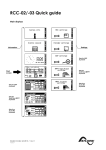
3.3 Frame
The Xcom-232i and the DTE exchange frames consist of a header of 14 bytes followed by
a variable number of data bytes and 2 bytes of checksum.
V1.3.1
start_byte
frame_flags
src_addr
dst_addr
data_length
header_checksum
frame_data
data_checksum
1 byte
1 byte
4 bytes
4 bytes
2 bytes =
N
2 bytes
N bytes
2 bytes
•
The start byte is always 0xAA
•
a frame_flags field, reserved, must be 0x00 in this version of the protocol
•
src_addr is the source address, 32 bit little endian
•
dest_addr is the destination address, 32 bit little endian
•
the length of the frame’s data, in byte
•
the checksum of the header, from frame_flags to data_length (included)
•
the data bytes
•
the checksum of all the data bytes of frame_data
•
The maximum number of frame_data is 242 (so that 14+242+2 = 256)
4 / 25
Technical specification
Xtender serial protocol
The checksum is computed with the following algorithm:
A = 0xFF
B=0
For I FROM 0 TO number_of_bytes -1 DO
A := (A + DATA[I]) mod 0x100;
B := (B + A) mod 0x100;
END
checksum[0] := A
checksum[1] := B
A and B are byte values and the addition is made modulo 256.
After an invalid parity bit, header or data checksum, the data link layer is reseted and
waits for an other frame.
3.4 Addressing the devices
address
devices
remarks
101 to 109
XTH and XTM inverters
ordered by the index
displayed on the RCC
301 to 331
MPPT
ordered by the index
displayed on the RCC
401
Xcom MS
501 to 503
Xcom-232i
601
BSP
1
alias for the gateway that the
DTE uses to communicate (the
Xcom-232i to which you speak
with RS-232)
3.5 Response delay
The response delay of the Xcom-232i can be up to 2 seconds. This is a good value for a
timeout in the DTE implementation.
V1.3.1
5 / 25
Technical specification
Xtender serial protocol
4. Application layer
The OSI layers 3 to 6 are not used. The application layer defines a number of
« services ». A DTE sends a request frame and waits for a response frame from the
Xcom-232i. If an error in the header checksum or data checksum is detected, there is no
response from the application layer and the Xcom-232i waits for another request as if
nothing has been received.
The Xcom-232i copies the src_addr of the request in the response dst_addr.
4.1 Services
The first two bytes of frame_data define the type of service and different flags for this
service.
service_flags
service_id
service_data
1 byte
1 byte
N bytes
service_flags:
BIT7-BIT2
:
reserved, must be all zero in this version of the protocol
BIT1
:
is_response flag, 0 if it is a request from the DTE to the Xcom-232i, 1
if it is response from the Xcom-232i
BIT0
:
error flag, 0 in case of success, 1 if an error occurred. In case of a
request, error is always 0.
service_id:
One of the following services, described later in this document:
READ_PROPERTY = 0x01
service_data:
The data specific to the service. In case of a problem the errors are reported in a servicespecific way, but the response has to include the error code described in the next section.
4.2 Object model
The different data accessible on each device are organized in object classes. Every object
class has a number of properties. The service READ_PROPERTY is used to read the
object’s properties.
V1.3.1
6 / 25
Technical specification
Xtender serial protocol
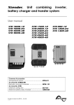
4.2.1 READ_PROPERTY service
This service is used to read an object’s property.
The DTE sends a request frame with the following frame_data:
flags
0x00
service_id
object_type
object_id
property_id
0x01
2 bytes
4 bytes
2 bytes
flags
:
is_response =0, error=0
service_id
:
0x01 for READ_PROPERTY
object_type
:
the object type identifier, defined later in this document
object_id
:
the object identifier, specific to each object type, i.e. two objects with
different type can have the same id
property_id
:
identify the property in the object
The RCC responds with a frame with the following frame_data:
service_flags
service_id
object_type
object_id
property_id
property_data
0x02 or 0x03
0x01
2 bytes
4 bytes
2 bytes
N bytes
flags
: flags_response = 1, error= 0 or 1
service_id
: 0x01 for READ_PROPERTY
object_type
: same as the request
object_id
: same as the request
property_id
: same as the request
property_data : If error=0 the value of the property, in the type of the property. If
error=1, two bytes identifying the error code.
V1.3.1
7 / 25
Technical specification
Xtender serial protocol
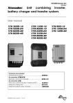
4.2.2 WRITE_PROPERTY service
This service is used to write an object’s property.
The DTE sends a request frame with the following frame_data:
flags
service_id
object_type
object_id
property_id
property_data
0x02
2 bytes
4 bytes
2 bytes
n byte
0x00
flags
:
is_response = 0, error = 0
service_id
:
0x02 for WRITE_PROPERTY
object_type
:
the object type identifier, defined later in this document
object_id
:
the object identifier, specific to each object type, i.e. two objects with
different types can have the same id
property_id
:
identify the property in the object
property_data : the data in the right data type.
The RCC responds with a frame with the following frame_data:
service_flags
service_id
object_type
object_id
property_id
error_id
0x02 or 0x03
0x02
2 bytes
4 bytes
2 bytes
0 or 2 bytes
flags
: flags_response = 1, error= 0 or 1
service_id
: 0x01 for READ_PROPERTY
object_type
: same as the request
object_id
: same as the request
property_id
: same as the request
property_data : If the flag error = 0, 0 byte of data if not, to byte of type bytes
identifying the error code.
4.2.3 Format
The property data are encoded in different formats described below. Some properties
have a format that can be different from one object to an other in the same object_type.
For example an the value_qsp of parameter can be an ENUM or a FLOAT depending on
the parameter id (identified by the object_id). In this case it is described here as type
DYNAMIC. The DTE must then know the exact type of the property for each object to
decode it.
INVALID_FORMAT = 0
BOOL = 1
V1.3.1
: binary data, 1 byte, 0 = false, 1 = true, other values are invalid
8 / 25
Technical specification
Xtender serial protocol
FORMAT = 2
: a property what define the format of an other property, 16 bit
integer
ENUM = 3
: a value that is part of a enumeration of possible values,
represented with a 16 bit integer
ERROR = 4
: 16 bit error code
INT32 = 5
: 32 bit signed value
FLOAT = 6
: float in 32 bit IEEE 754 format, little endian
STRING = 7
: ISO_8859-15 string of 8 bit characters
DYNAMIC = 8
: a property with a different format for each object id
BYTE_STREAM = 9 : a stream a byte of abitrary length
example of dynamic value:
an object class has the property “type” of format FORMAT and the property “value” of
format DYNAMIC.
for the object x, if “type” = 6 (FLOAT), “value” is a 4 byte IEEE 754 little endian float.
4.3 Error codes
The following error codes can be returned:
name
error_id
meaning
INVALID_FRAME
0x0001
malformed frame
DEVICE_NOT_FOUND
0x0002
wrong dst_addr field
RESPONSE_TIMEOUT
0x0003
no response of the server
SERVICE_NOT_SUPPORTED
0x0011
wrong service_id field
INVALID_SERVICE_ARGUMENT
0x0012
wrong service_data
SCOM_ERROR_GATEWAY_BUSY
0x0013
gateway (for example XCOM-232i) busy
TYPE_NOT_SUPPORTED
0x0021
the object_type requested doesn't exist
OBJECT_ID_NOT_FOUND
0x0022
no object with this object_id was found
PROPERTY_NOT_SUPPORTED
0x0023
the property identified by property_id doesn't
exist
INVALID_DATA_LENGTH
0x0024
the field property_data has an invalid number of
bytes
PROPERTY_IS_READ_ONLY
0x0025
a writing to this property is not allowed
INVALID_DATA
0x0026
this value is impossible for this property
DATA_TOO_SMALL
0x0027
the value is below the minimum limit
DATA_TOO_BIG
0x0028
the value is above the maximum limit
V1.3.1
9 / 25
Technical specification
Xtender serial protocol
WRITE_PROPERTY_FAILED
0x0029
writing is possible, but failed
READ_PROPERTY_FAILED
0x002A
readind is possible, but failed
ACCESS_DENIED
0x002B
insufficient user access
INVALID_SHELL_ARG
0x0081
the command line tool used received the wrong
arguments
4.4 System state objects
These objects are the information about the current state of the system. They cannot be
modified and their values change during the operation of the system.
object_type = 0x01
object_id : see the table in next section
4.4.1 Properties
Name
property_id
format
remark
Value
0x01
DYNAMIC
variable length, see the format in following
table
4.4.2 Available system states on the Xtender Inverter
The values defined in the following table are accessible on the Xtender XTH and XTM
inverters. The states available are the same as the values that can be chosen to be
displayed on the RCC.
The system states are related with inverter parameters that you can be configured with
the RCC. The description of the functionalities for each parameter can be found in the
RCC manual with the index by id number at the end.
V1.3.1
10 / 25
Technical specification
Xtender serial protocol
id Description
3000 Battery voltage
3001 Battery temperature
Ubat
Tbat
unit on
the
RCC
Vdc
°C
3005 Battery charge
current
3006 Battery voltage ripple
3010 Battery cycle phase
Ibat (m)
Adc
Ubat ond
Phase
Vrip
3011 Input voltage AC-In
3012 AC input current ACIn
3013 Input power AC-In
3014 Input frequency
3018 Power sharing active
3019 Boost active
3020 State of transfer
relay
3021 Output voltage ACOut
3022 Output current ACOut
3023 Output power ACOut
3024 Output frequency
3028 Operating state
U in
I in
Vac
Aac
V
0: invalid value
1:Bulk
2: Absorpt.
3: Equalise
4: Floating
5: R.float.
6: Per.abs.
7: Mixing
8: Forming
V
A
P in
F in
P sharing
Boost
Transfert
kVA
Hz
kVA
Hz
U out
Vac
0: Opened
1: Closed
V
I out
Aac
A
FLOAT
P out
kVA
kVA
FLOAT
F out
Mode
Hz
Hz
0: invalid value
1: Inverter
2: Charger
3: Boost
4: Injection
FLOAT
ENUM
3030 State of output relay
Rel out
ENUM
3031 State of auxiliary
relay I
3032 State of auxiliary
relay II
3049 State of the system
Aux 1
3051 Search mode state
SB state
3076 Discharge of battery
of the previous day
3078 Discharge of battery
of the current day
3080 Energy from AC-In of
the previous day
3081 Energy from AC-In of
the current day
3082 Consumers energy of
the previous day
3083 Consumers energy of
the current day
E out YD
E2O
0: Opened
1: Closed
0: Opened
1: Closed
0: Opened
1: Closed
0: Off
1: On
0: Off
1: On
kWh
E out Day
E1O
kWh
FLOAT
Eac in YD
E2
kWh
FLOAT
Eac in
Day
Eac out
YD
Eac out
Dy
E1
kWh
FLOAT
E2
kWh
FLOAT
E1
kWh
FLOAT
V1.3.1
short
name
Aux 2
Sys state
unit
FORMAT related parameter or
description
V
°C
no sensor :
return ~32767
°C
A
FLOAT
FLOAT
FLOAT
ENUM
FLOAT
FLOAT
BOOL
BOOL
ENUM
11 / 25
value given by the external
battery temperature sensor
BTS-01
FLOAT
see parameter {1137}
FLOAT
FLOAT
see parameter {1107}
see parameter {1126}
FLOAT
give the current working
mode of the inverter. See
{1107} for Boost, {1522} for
Injection (grid-feeding),
charger and inverter mode are
oblivious.
ENUM
see parameter {1201}
ENUM
see parameter {1201}
ENUM
ENUM
FLOAT
see parameter {1187}
Technical specification
Xtender serial protocol
4.4.3 Available system states on the BSP
As on the inverter, all values that can be displayed on the RCC can be read.
id Description
V1.3.1
7000 Battery voltage
Ubat
unit on
the
RCC
V
7001 Battery current
Ibat
A
A
FLOAT
7002 State of Charge
SOC
%
%
FLOAT
7003 Power
C_cons
W
%
FLOAT
7004 Remaining autonomy
Trem
minutes
minutes
FLOAT
7006 Relative capacity
Crel
%
%
FLOAT
7007 Ah charged today
0d<
Ah
Ah
FLOAT
7008 Ah discharged today
0d>
Ah
Ah
FLOAT
7009 Ah charged yesterday
-1d<
Ah
Ah
FLOAT
7010 Ah discharged yesterday -1d>
Ah
Ah
FLOAT
7011 Total kAh charged
tot<
kAh
kAh
FLOAT
7012 Total kAh discharged
tot>
kAh
kAh
FLOAT
7013 Total time
Ttot
days
days
FLOAT
cus>
Ah
Ah
cus<
Ah
Ah
7019 Custom counter duration Tcus
h
h
FLOAT
7029 Battery temperature
°C
°C
FLOAT
Custom
7017 counter
charge
Custom
7018 counter
discharge
short
name
unit
FORMAT related parameter or
description
V
FLOAT
Ah
FLOAT
Ah
FLOAT
Tbat
12 / 25
Technical specification
Xtender serial protocol
4.5 Parameter objects
All parameters accessible from the remote control can also be modified with the protocol.
The behaviour is the same as if a physical person changes the value with the remote
control buttons. Currently, only changes at the level qsp are possible.
Values of type FLOAT can take any value between min and max but are rounded to the
edition step on the remote control.
object_type = 0x02
4.5.1 Properties
Name
property_id
format
Remark
value_qsp
0x05
DYNAMIC
the value that can be entered on the remote
control in level qsp or installer.
min_qsp
0x06
DYNAMIC
Minimum that can be entered on the remote
control in level qsp or installer.
max_qsp
0x07
DYNAMIC
Maximum that can be entered on the remote
control in level qsp or installer.
level_qsp
0x08
ENUM
accessibility level of this parameter modifiable
in level qsp or installer.
4.5.2 Values of level properties
The property level_qsp of type ENUM can take the following values:
Name
value
VIEW_ONLY
0x00
BASIC
0x10
EXPERT
0x20
INSTALLER
0x30
QSP
0x40
4.5.3 Available parameters on the Xtender Inverter
The change of parameters when the inverters are in operation should be done carefully.
The modification of parameters can restart the corresponding algorithm inside the
inverter, and thus the change of a value in a cyclic way could sometimes lead to
unexpected behaviour.
object_id : a number starting at 1000. See the complete parameter references at the end
of the RCC User manual.
V1.3.1
13 / 25
Technical specification
Xtender serial protocol
4.5.4 Cyclic write of parameters on the Xtender Inverter
The Xtender inverter store the parameter values in a non volatile flash memory. Because
of the endurance of this memory, the number of write on a single parameter property is
only garanted for 1000 write operations.
To allow the cyclic write of parameters without count limit, the parameter {1550}
“Parameters saved in flash memory” as been introduced in the Xtender software.
This parameter has the value “yes” by default. A write of “no” to this parameter value
stop the write in the non-volatile flash memory. This operation is written in the flash
memory only the first time, so consecutive writes of the value “no” to {1550} can be
repeated without limit.
After parameter {1550} has been set to “no”, all other parameters can be written
without count limit. Because the values of all other parameters are not stored in flash,
the read operation will give the values before {1550} as be changed to “no”. Also, after a
reset the old values will be taken.
To use the inverter with cyclic write operations you must:
-
ensure that all inverters have a firmware version >= 1.4.6
-
set the parameter {1550} to “no” on all targeted inverter
-
avoid to write cyclically on other devices like BSP, RCC, ...
-
ensure that no “reset default/factory settings”, “apply configuration
(masterfile)” or modification with the remote control change {1550} to “yes”
file
It is a good pratice to cyclically write “no” to {1550}.
A write of “yes” to the parameter {1550} reactivate the write in flash. It will be written in
the flash every time and should not be used more that 1000 time.
4.5.5 Hours encoding
the hours encoding is in minute since 00:00 in INT32. For example 13:41 is 13*60+41 =
821.
4.5.6 Days of the week encoding
The days of the week selection (parameters {1205}, for example) is coded as a bit field
in a INT32. A day selected as it bit set to 1.
bit
BIT31-7
BIT6
BIT5
BIT4
BIT3
BIT2
BIT1
BIT0
day of the week
undefined
SU
SA
FR
TH
WE
TU
MO
4.5.7 Month of the year encoding
The month of the year selection (parameters {1479}, for example) is coded as a bit field
in a INT32. A month selected as it bit set to 1. January is BIT0 and December BIT11. The
BIT31 to 12 are undefined.
V1.3.1
14 / 25
Technical specification
Xtender serial protocol
4.5.8 Date encoding
The Date (parameters {5002}, for example) is coded as a INT32. The value is the
number of second since 1.1.1970 00:00:00.
4.5.9 Signal encoding
The Signal (parameters {1468}, for example) is coded as a INT32. To send a signal, you
must write the value 1 to the parameter value.
V1.3.1
15 / 25
Technical specification
Xtender serial protocol
5. Examples of frames
The byte stream is represented in hexadecimal. As specified above, the encoding is little
endian.
5.1 Command line tool
To help the implementation of the protocol we supply the command line tool scom.exe.
Please contact Studer Innotec for the last version of the executable.
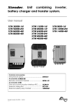
5.2 Read the value of a system state
generated by the command:
>scom.exe --port=COM3 --verbose=3 read_property src_addr=1
object_type=1 object_id=3000 property_id=1 format=FLOAT
dst_addr=101
Request
start_byte
frame_flags
AA
00
dst_addr = 101
src_addr
=1
data_length
= 10
(first inverter)
01000000
65000000
flags :
service_id =
is_response = false
error = false
READ_PROPERTY
00
0A00
object_type =
header_checksum
frame_data
data_checksum
6F71
10 bytes
C590
object_id =
SYSTEM_STATE
property_id
=
3000
value
01
0100
B80B0000
0100
Total number of bytes: 14+10+2 = 26 bytes
Response
start_byte
frame_flags
AA
00
dst_addr = 1
src_addr
=101
65000000
data_length
= 14
01000000
0E00
flags :
service_id =
is_response = true
error = false
READ_PROPERTY
SYSTEM_STATE
02
01
0100
V1.3.1
object_type =
16 / 25
header_checksum
frame_data
data_checksum
7309
14 bytes
6357
object_id =
property_id =
value=
3000
value
23.453125
B80B0000
0100
00A0BB41
Technical specification
Xtender serial protocol
Total number of bytes: 14+14+2 = 30 bytes
5.3 Write the qsp_value of a parameter
Set the battery charge current at 12.0 A.
generated by the command:
>scom.exe --port=COM3 --verbose=3 write_property src_addr=1 dst_addr=101
object_type=2 object_id=1138 property_id=5 format=FLOAT value=12.0
Request
start_byte
frame_flags
src_addr=1
dst_addr=101
data_length
= 14
header_checksum
frame_data
data_checksum
0xAA
00
01000000
65000000
0E00
7379
14 bytes
FF9B
flags :
service_id =
object_type =
object_id =
property_id =
is_response
=false
error
=false
WRITE_PROPERTY
PARAMETER
1138
value_qsp
00
02
0200
72040000
0500
property_data
= 12.0
00004041
Total number of bytes: 14+14+2 = 30 bytes
Response
start_byte
frame_flags
src_addr=1
dst_addr=101
data_length
= 10
header_checksum
frame_data
data_checksum
0xAA
00
65000000
01000000
0A00
6F01
10 bytes
0x80F6
Total
flags :
service_id =
object_type =
object_id =
property_id =
is_response
=true
error
=false
WRITE_PROPERTY
PARAMETER
1138
value_qsp
02
02
0200
72040000
0500
number of bytes: 14+10+2 = 26 bytes
V1.3.1
17 / 25
Technical specification
Xtender serial protocol
6. Annexes
6.1 Xtender parameters
Level
Basic
Basic
Basic
Basic
Basic
Basic
Basic
Basic
Basic
Inst.
Expert
Expert
Basic
Expert
Expert
Expert
Expert
Expert
Expert
Expert
Expert
Expert
Expert
Expert
Expert
Expert
Expert
Expert
Expert
Expert
Expert
Expert
Expert
Expert
Expert
Expert
Expert
Expert
Expert
Expert
Expert
Expert
Expert
Expert
Expert
Expert
Expert
Expert
Expert
Expert
Expert
Expert
Expert
Expert
V1.3.1
User
ref.
1100
1551
1107
1138
1126
1124
1552
1187
1395
1287
1137
1125
1138
1139
1568
1108
1531
1191
1532
1109
1190
1110
1194
1195
1307
1298
1121
1122
1140
1467
1141
1142
1143
1144
1145
1146
1149
1147
1148
1451
1155
1156
1157
1158
1159
1160
1161
1452
1163
1162
1291
1290
1164
1165
Parameter
BASIC SETTINGS
Basic parameters set with buttons (inside XTS)
Maximum current of AC source (Input limit)
Battery charge current
Smart-Boost allowed
Inverter allowed
Type of detection of AC-input loss (UPS)
Standby level
Restore default settings
Restore factory settings
BATTERY MANAGEMENT AND CYCLE
Charger allowed
Battery charge current
Battery temperature compensation
Undervoltage
Battery undervoltage level without load
Battery undervoltage dynamic compensation
Battery undervoltage dynamic compensation
Kind of dynamic compensation
Battery undervoltage level at full load
Battery undervoltage duration before turn off
Restart voltage after batteries undervoltage
Battery adaptive low voltage (B.L.O)
Max voltage for adaptive low voltage
Reset voltage for adaptive correction
Increment step of the adaptive low voltage
Battery overvoltage level
Restart voltage level after an battery overvoltage
Battery floating level
Force phase of floating
New cycle menu
Force a new cycle
Battery voltage level 1 to start a new cycle
Time period under battery voltage level 1 to start a new cycle
Battery voltage level 2 to start a new cycle
Time period under battery voltage level 2 to start a new cycle
New cycle priority on absorption and equalization phases
Battery cycling restricted
Minimal delay between cycles
Phase of absorption
Absorption phase allowed
Battery absorption voltage
Absorption duration
End of absorption triggered with current
Current limit to quit the absorption phase
Maximal frequency of absorption control
Minimal delay since last absorption
Phase of equalization
Equalization allowed
Force equalization
Equalization before absorption phase
Equalization current
Equalization voltage
Equalization duration
18 / 25
Scom format
ONLY LEVEL
BOOL
FLOAT
FLOAT
BOOL
BOOL
ENUM
FLOAT
INT32
INT32
ONLY LEVEL
BOOL
FLOAT
FLOAT
ONLY LEVEL
FLOAT
ONLY LEVEL
BOOL
BOOL
FLOAT
FLOAT
FLOAT
BOOL
FLOAT
FLOAT
FLOAT
FLOAT
FLOAT
FLOAT
INT32
ONLY LEVEL
INT32
FLOAT
FLOAT
FLOAT
FLOAT
BOOL
BOOL
FLOAT
ONLY LEVEL
BOOL
FLOAT
FLOAT
BOOL
FLOAT
BOOL
FLOAT
ONLY LEVEL
BOOL
INT32
BOOL
FLOAT
FLOAT
FLOAT
Technical specification
Xtender serial protocol
Expert
Expert
Expert
Expert
Expert
Expert
Expert
Expert
Expert
Expert
Expert
Expert
Expert
Expert
Expert
Basic
Expert
Expert
Expert
Expert
Expert
Expert
Expert
Expert
Expert
Basic
Expert
Expert
Expert
Expert
QSP
Expert
Expert
Expert
Basic
Basic
Expert
Expert
Expert
Expert
Expert
Expert
Expert
Expert
Expert
Expert
Basic
Expert
Expert
Expert
Expert
Inst.
QSP
Expert
Expert
Expert
Expert
Expert
Expert
Expert
Expert
V1.3.1
1166
1284
1285
1168
1169
1453
1170
1171
1172
1454
1173
1174
1175
1176
1186
1124
1286
1548
1560
1112
1536
1549
1546
1534
1420
1187
1189
1188
1599
1438
1572
1197
1128
1580
1126
1107
1471
1566
1567
1527
1554
1309
1433
1553
1295
1436
1552
1510
1199
1198
1200
1432
1500
1505
1506
1507
1575
1201
1202
1497
1203
Number of cycles before an equalization
Equalization at fixed interval
Weeks between equalizations
End of equalization triggered with current
Current limit to quit the equalization phase
Phase of reduced floating
Reduced floating allowed
Floating duration before reduced floating
Reduced floating voltage
Phase of periodic absorption
Periodic absorption allowed
Periodic absorption voltage
Reduced floating duration before periodic absorption
Periodic absorption duration
INVERTER
Inverter allowed
AC Output voltage
AC voltage increase according to battery voltage
Max AC voltage increase with battery voltage
Inverter frequency
Inverter frequency increase when battery full
Inverter frequency increase according to battery voltage
Max frequency increase
Speed of voltage or frequency change in function of battery
Standby and turn on
Standby level
Time delay between standby pulses
Standby number of pulses
Softstart duration
Solsafe presence Energy source at AC-Out side
Modulator ru_soll
AC-IN AND TRANSFER
Transfer relay allowed
Delay before closing transfer relay
Smart-Boost allowed
Maximum current of AC source (Input limit)
Max input current modification
Use an alternate max input current
Second maximum current of AC source (Input limit)
Decrease max input limit current with AC-In voltage
Decrease max input limit activated by remote entry
AC input low limit voltage to allow charger function
Adaptation range of the input current according to the input voltage
Speed of input limit increase
Charge current decrease coef. at voltage limit to turn back in inverter mode
Overrun AC source current limit without opening the transfer relay (Input limit)
Type of detection of AC-input loss (UPS)
Tolerance on detection of AC-input loss (tolerant UPS mode)
Input voltage giving an opening of the transfer relay with delay
Time delay before opening of transfer relay
Input voltage giving an immediate opening of the transfer relay (UPS)
Absolute max limit for input voltage
Standby of the charger allowed
Delta frequency allowed above the standard input frequency
Delta frequency allowed under the standard input frequency
Duration with frequency error before opening the transfer
AC-IN current active filtering
AUXILIARY CONTACT 1
Operating mode (AUX 1)
Combination of the events for the auxiliary contact (AUX 1)
Temporal restrictions (AUX 1)
19 / 25
FLOAT
BOOL
FLOAT
BOOL
FLOAT
ONLY LEVEL
BOOL
FLOAT
FLOAT
ONLY LEVEL
BOOL
FLOAT
FLOAT
FLOAT
ONLY LEVEL
BOOL
FLOAT
BOOL
FLOAT
FLOAT
BOOL
BOOL
FLOAT
FLOAT
ONLY LEVEL
FLOAT
FLOAT
FLOAT
FLOAT
BOOL
BOOL
ONLY LEVEL
BOOL
FLOAT
BOOL
FLOAT
ONLY LEVEL
BOOL
FLOAT
BOOL
BOOL
FLOAT
FLOAT
FLOAT
FLOAT
BOOL
ENUM
FLOAT
FLOAT
FLOAT
FLOAT
FLOAT
BOOL
FLOAT
FLOAT
FLOAT
BOOL
ONLY LEVEL
ENUM
BOOL
ONLY LEVEL
Technical specification
Xtender serial protocol
Expert
Expert
Expert
Expert
Expert
Expert
Expert
Expert
Expert
Expert
Expert
Expert
Inst.
Inst.
Inst.
Inst.
Inst.
Inst.
Inst.
Inst.
Expert
Expert
Expert
Expert
Expert
Expert
Expert
Expert
Expert
Expert
Expert
Expert
Expert
Expert
Expert
Expert
Expert
Expert
Expert
Expert
Expert
Expert
Expert
Expert
Expert
Expert
Expert
Expert
Expert
Expert
Expert
Expert
Expert
Expert
Expert
Expert
Expert
Expert
Expert
Expert
Expert
V1.3.1
1204
1205
1206
1207
1208
1209
1210
1211
1212
1213
1214
1215
1216
1217
1218
1219
1220
1221
1222
1223
1269
1270
1271
1272
1273
1274
1275
1276
1277
1278
1279
1280
1281
1455
1225
1518
1543
1226
1227
1228
1229
1520
1231
1232
1233
1234
1235
1236
1237
1238
1239
1240
1242
1243
1244
1529
1245
1288
1246
1247
1248
Program 1 (AUX 1)
Day of the week (AUX 1)
Start hour (AUX 1)
End hour (AUX 1)
Program 2 (AUX 1)
Day of the week (AUX 1)
Start hour (AUX 1)
End hour (AUX 1)
Program 3 (AUX 1)
Day of the week (AUX 1)
Start hour (AUX 1)
End hour (AUX 1)
Program 4 (AUX 1)
Day of the week (AUX 1)
Start hour (AUX 1)
End hour (AUX 1)
Program 5 (AUX 1)
Day of the week (AUX 1)
Start hour (AUX 1)
End hour (AUX 1)
Contact active with a fixed time schedule (AUX 1)
Program 1 (AUX 1)
Day of the week (AUX 1)
Start hour (AUX 1)
End hour (AUX 1)
Program 2 (AUX 1)
Day of the week (AUX 1)
Start hour (AUX 1)
End hour (AUX 1)
Program 3 (AUX 1)
Day of the week (AUX 1)
Start hour (AUX 1)
End hour (AUX 1)
Contact active on event (AUX 1)
Xtender is OFF (AUX 1)
Xtender ON (AUX 1)
Remote entry (AUX 1)
Battery undervoltage (AUX 1)
Battery overvoltage (AUX 1)
Inverter or Smart- Boost overload (AUX 1)
Overtemperature (AUX 1)
No overtemperature (AUX 1)
Active charger (AUX 1)
Active inverter (AUX 1)
Active Smart-Boost (AUX 1)
AC input presence but with fault (AUX 1)
AC input presence (AUX 1)
Transfer relay ON (AUX 1)
AC out presence (AUX 1)
Bulk charge phase (AUX 1)
Absorption phase (AUX 1)
Equalization phase (AUX 1)
Floating (AUX 1)
Reduced floating (AUX 1)
Periodic absorption (AUX 1)
Autonomy test running (AUX 1)
Contact active according to battery voltage (AUX 1)
Use dynamic compensation of battery level (AUX 1)
Battery voltage 1 activate (AUX 1)
Battery voltage 1 (AUX 1)
Delay 1 (AUX 1)
20 / 25
ONLY LEVEL
ENUM
INT32
INT32
ONLY LEVEL
ENUM
INT32
INT32
ONLY LEVEL
ENUM
INT32
INT32
ONLY LEVEL
ENUM
INT32
INT32
ONLY LEVEL
ENUM
INT32
INT32
ONLY LEVEL
ONLY LEVEL
ENUM
INT32
INT32
ONLY LEVEL
ENUM
INT32
INT32
ONLY LEVEL
ENUM
INT32
INT32
ONLY LEVEL
BOOL
BOOL
BOOL
BOOL
BOOL
BOOL
BOOL
BOOL
BOOL
BOOL
BOOL
BOOL
BOOL
BOOL
BOOL
BOOL
BOOL
BOOL
BOOL
BOOL
BOOL
BOOL
ONLY LEVEL
BOOL
BOOL
FLOAT
FLOAT
Technical specification
Xtender serial protocol
Expert
Expert
Expert
Expert
Expert
Expert
Expert
Expert
Expert
Expert
Expert
Expert
Expert
Expert
Expert
Expert
Expert
Expert
Expert
Expert
Expert
Inst.
Inst.
Inst.
Inst.
Expert
Expert
Expert
Expert
Expert
Expert
Expert
Expert
Expert
Expert
Expert
Expert
Expert
Expert
Expert
Expert
Expert
Expert
Expert
Expert
Expert
Expert
Expert
Expert
Expert
Expert
Expert
Expert
Expert
Expert
Expert
Expert
Inst.
Inst.
Inst.
Inst.
V1.3.1
1249
1250
1251
1252
1253
1254
1255
1256
1516
1257
1258
1259
1260
1261
1262
1263
1264
1265
1266
1267
1268
1503
1446
1447
1448
1501
1439
1440
1581
1582
1583
1584
1585
1586
1587
1441
1588
1589
1512
1514
1569
1310
1311
1498
1312
1313
1314
1315
1316
1317
1318
1319
1320
1321
1322
1323
1324
1325
1326
1327
1328
Battery voltage 2 activate (AUX 1)
Battery voltage 2 (AUX 1)
Delay 2 (AUX 1)
Battery voltage 3 activate (AUX 1)
Battery voltage 3 (AUX 1)
Delay 3 (AUX 1)
Battery voltage to deactivate (AUX 1)
Delay to deactivate (AUX 1)
Deactivate if battery in floating phase (AUX 1)
Contact active with inverter power or Smart-Boost (AUX 1)
Inverter power level 1 activate (AUX 1)
Power level 1 (AUX 1)
Time delay 1 (AUX 1)
Inverter power level 2 activate (AUX 1)
Power level 2 (AUX 1)
Time delay 2 (AUX 1)
Inverter power level 3 activate (AUX 1)
Power level 3 (AUX 1)
Time delay 3 (AUX 1)
Inverter power level to deactivate (AUX 1)
Time delay to deactivate (AUX 1)
Contact active according to battery temperature (AUX 1) With BSP or BTS
Contact activated with the temperature of battery (AUX 1)
Contact activated over (AUX 1)
Contact deactivated below (AUX 1)
Contact active according to SOC (AUX 1) Only with BSP
Contact activated with the SOC 1 of battery (AUX 1)
Contact activated below SOC 1 (AUX 1)
Delay 1 (AUX 1)
Contact activated with the SOC 2 of battery (AUX 1)
Contact activated below SOC 2 (AUX 1)
Delay 2 (AUX 1)
Contact activated with the SOC 3 of battery (AUX 1)
Contact activated below SOC 3 (AUX 1)
Delay 3 (AUX 1)
Contact deactivated over SOC (AUX 1)
Delay to deactivate (AUX 1)
Deactivate if battery in floating phase (AUX 1)
Security, maximum time of contact (AUX 1)
Maximum time of operation of contact (AUX 1)
Reset all settings (AUX 1)
AUXILIARY CONTACT 2
Operating mode (AUX 2)
Combination of the events for the auxiliary contact (AUX 2)
Temporal restrictions (AUX 2)
Program 1 (AUX 2)
Day of the week (AUX 2)
Start hour (AUX 2)
End hour (AUX 2)
Program 2 (AUX 2)
Day of the week (AUX 2)
Start hour (AUX 2)
End hour (AUX 2)
Program 3 (AUX 2)
Day of the week (AUX 2)
Start hour (AUX 2)
End hour (AUX 2)
Program 4 (AUX 2)
Day of the week (AUX 2)
Start hour (AUX 2)
End hour (AUX 2)
21 / 25
BOOL
FLOAT
FLOAT
BOOL
FLOAT
FLOAT
FLOAT
FLOAT
BOOL
ONLY LEVEL
BOOL
FLOAT
FLOAT
BOOL
FLOAT
FLOAT
BOOL
FLOAT
FLOAT
FLOAT
FLOAT
ONLY LEVEL
BOOL
FLOAT
FLOAT
ONLY LEVEL
BOOL
FLOAT
FLOAT
BOOL
FLOAT
FLOAT
BOOL
FLOAT
FLOAT
FLOAT
FLOAT
BOOL
BOOL
FLOAT
INT32
ONLY LEVEL
ENUM
BOOL
ONLY LEVEL
ONLY LEVEL
ENUM
INT32
INT32
ONLY LEVEL
ENUM
INT32
INT32
ONLY LEVEL
ENUM
INT32
INT32
ONLY LEVEL
ENUM
INT32
INT32
Technical specification
Xtender serial protocol
Inst.
Inst.
Inst.
Inst.
Expert
Expert
Expert
Expert
Expert
Expert
Expert
Expert
Expert
Expert
Expert
Expert
Expert
Expert
Expert
Expert
Expert
Expert
Expert
Expert
Expert
Expert
Expert
Expert
Expert
Expert
Expert
Expert
Expert
Expert
Expert
Expert
Expert
Expert
Expert
Expert
Expert
Expert
Expert
Expert
Expert
Expert
Expert
Expert
Expert
Expert
Expert
Expert
Expert
Expert
Expert
Expert
Expert
Expert
Expert
Expert
Expert
V1.3.1
1329
1330
1331
1332
1378
1379
1380
1381
1382
1383
1384
1385
1386
1387
1388
1389
1390
1456
1333
1519
1544
1334
1335
1336
1337
1521
1339
1340
1341
1342
1343
1344
1345
1346
1347
1348
1350
1351
1352
1530
1353
1354
1355
1356
1357
1358
1359
1360
1361
1362
1363
1364
1365
1517
1366
1367
1368
1369
1370
1371
1372
Program 5 (AUX 2)
Day of the week (AUX 2)
Start hour (AUX 2)
End hour (AUX 2)
Contact active with a fixed time schedule (AUX 2)
Program 1 (AUX 2)
Day of the week (AUX 2)
Start hour (AUX 2)
End hour (AUX 2)
Program 2 (AUX 2)
Day of the week (AUX 2)
Start hour (AUX 2)
End hour (AUX 2)
Program 3 (AUX 2)
Day of the week (AUX 2)
Start hour (AUX 2)
End hour (AUX 2)
Contact active on event (AUX 2)
Xtender is OFF (AUX 2)
Xtender ON (AUX 2)
Remote entry (AUX 2)
Battery undervoltage (AUX 2)
Battery overvoltage (AUX 2)
Inverter or Smart-Boost overload (AUX 2)
Overtemperature (AUX 2)
No overtemperature (AUX 2)
Active charger (AUX 2)
Active inverter (AUX 2)
Active Smart-Boost (AUX 2)
AC input presence but with fault (AUX 2)
AC input presence (AUX 2)
Transfer contact ON (AUX 2)
AC out presence (AUX 2)
Bulk charge phase (AUX 2)
Absorption phase (AUX 2)
Equalization phase (AUX 2)
Floating (AUX 2)
Reduced floating (AUX 2)
Periodic absorption (AUX 2)
Autonomy test running (AUX 2)
Contact active according to battery voltage (AUX 2)
Use dynamic compensation of battery level (AUX 2)
Battery voltage 1 activate (AUX 2)
Battery voltage 1 (AUX 2)
Delay 1 (AUX 2)
Battery voltage 2 activate (AUX 2)
Battery voltage 2 (AUX 2)
Delay 2 (AUX 2)
Battery voltage 3 activate (AUX 2)
Battery voltage 3 (AUX 2)
Delay 3 (AUX 2)
Battery voltage to deactivate (AUX 2)
Delay to deactivate (AUX 2)
Deactivate if battery in floating phase (AUX 2)
Contact active with inverter power or Smart-Boost (AUX 2)
Inverter power level 1 activate (AUX 2)
Power level 1 (AUX 2)
Time delay 1 (AUX 2)
Inverter power level 2 activate (AUX 2)
Power level 2 (AUX 2)
Time delay 2 (AUX 2)
22 / 25
ONLY LEVEL
ENUM
INT32
INT32
ONLY LEVEL
ONLY LEVEL
ENUM
INT32
INT32
ONLY LEVEL
ENUM
INT32
INT32
ONLY LEVEL
ENUM
INT32
INT32
ONLY LEVEL
BOOL
BOOL
BOOL
BOOL
BOOL
BOOL
BOOL
BOOL
BOOL
BOOL
BOOL
BOOL
BOOL
BOOL
BOOL
BOOL
BOOL
BOOL
BOOL
BOOL
BOOL
BOOL
ONLY LEVEL
BOOL
BOOL
FLOAT
FLOAT
BOOL
FLOAT
FLOAT
BOOL
FLOAT
FLOAT
FLOAT
FLOAT
BOOL
ONLY LEVEL
BOOL
FLOAT
FLOAT
BOOL
FLOAT
FLOAT
Technical specification
Xtender serial protocol
Expert
Expert
Expert
Expert
Expert
Inst.
Inst.
Inst.
Inst.
Inst.
Expert
Expert
Expert
Expert
Expert
Expert
Expert
Expert
Expert
Expert
Expert
Expert
Expert
Expert
Expert
Expert
Expert
Expert
Expert
Expert
Expert
Expert
Expert
Expert
Expert
Expert
Expert
Expert
Expert
Expert
Expert
Expert
Expert
Expert
Inst.
Inst.
Expert
Expert
Expert
Expert
Expert
Expert
Expert
Expert
Expert
Expert
Expert
Expert
Expert
Expert
Expert
V1.3.1
1373
1374
1375
1376
1377
1504
1457
1458
1459
1460
1502
1442
1443
1590
1591
1592
1593
1594
1595
1596
1444
1597
1598
1513
1515
1570
1489
1491
1493
1492
1494
1574
1101
1537
1545
1538
1539
1540
1541
1542
1566
1567
1554
1576
1578
1579
1296
1297
1565
1129
1130
1304
1404
1305
1405
1131
1132
1533
1134
1111
1484
Inverter power level 3 activate (AUX 2)
Power level 3 (AUX 2)
Time delay 3 (AUX 2)
Inverter power level to deactivate (AUX 2)
Time delay to deactivate (AUX 2)
Contact active according to battery temperature (AUX 2) With BSP or BTS
Contact activated with the temperature of battery (AUX 2)
Contact activated over (AUX 2)
Contact deactivated below (AUX 2)
Contact activated only if the battery is charged (AUX 2)
Contact active according to SOC (AUX 2) Only with BSP
Contact activated with the SOC 1 of battery (AUX 2)
Contact activated below SOC 1 (AUX 2)
Delay 1 (AUX 2)
Contact activated with the SOC 2 of battery (AUX 2)
Contact activated below SOC 2 (AUX 2)
Delay 2 (AUX 2)
Contact activated with the SOC 3 of battery (AUX 2)
Contact activated below SOC 3 (AUX 2)
Delay 3 (AUX 2)
Contact deactivated over SOC (AUX 2)
Delay to deactivate (AUX 2)
Deactivate if battery in floating phase (AUX 2)
Security, maximum time of contact (AUX 2)
Maximum time of operation of contact (AUX 2)
Reset all settings (AUX 2)
AUXILIARY CONTACTS 1 AND 2 EXTENDED FUNCTIONS
Generator control active
Number of starting attempts
Starter pulse duration (with AUX2)
Time before a starter pulse
Main contact hold/interrupt time
SYSTEM
Remote entry (Remote ON/OFF)
Remote entry active
Prohibits transfert relay
Prohibits inverter
Prohibits charger
Prohibits Smart-Boost
Prohibits grid feeding
Use an alternate max input current
Second maximum current of AC source (Input limit)
Decrease max input limit activated by remote entry
ON/OFF command
Activated by AUX1 state
Prohibits battery priority
Batteries priority as energy source
Battery priority voltage
Buzzer alarm duration
Auto restarts
After battery undervoltage
Number of batteries undervoltage allowed before definitive stop
Time period for batteries undervoltages counting
Number of batteries critical undervoltage allowed before definitive stop
Time period for critical batteries undervoltages counting
After battery overvoltage
After inverter or Smart-Boost overload
Delay to restart after an overload
After overtemperature
Autostart to the battery connection
System earthing (Earth - Neutral)
23 / 25
BOOL
FLOAT
FLOAT
FLOAT
FLOAT
ONLY LEVEL
BOOL
FLOAT
FLOAT
BOOL
ONLY LEVEL
BOOL
FLOAT
FLOAT
BOOL
FLOAT
FLOAT
BOOL
FLOAT
FLOAT
FLOAT
FLOAT
BOOL
BOOL
FLOAT
INT32
ONLY LEVEL
BOOL
FLOAT
FLOAT
FLOAT
FLOAT
ONLY LEVEL
ONLY LEVEL
BOOL
BOOL
BOOL
BOOL
BOOL
BOOL
BOOL
FLOAT
BOOL
BOOL
BOOL
BOOL
BOOL
FLOAT
FLOAT
ONLY LEVEL
BOOL
FLOAT
FLOAT
FLOAT
FLOAT
BOOL
BOOL
FLOAT
BOOL
BOOL
ONLY LEVEL
Technical specification
Xtender serial protocol
Expert
Expert
Expert
Expert
Expert
Expert
Expert
Expert
Expert
Expert
Expert
Expert
Expert
Expert
Expert
Inst.
Inst.
Inst.
Expert
Expert
Expert
Expert
Expert
Expert
Expert
Expert
Inst.
Inst.
Expert
Expert
Expert
Expert
Expert
Expert
1485
1486
1473
1474
1495
1475
1476
1477
1478
1496
1479
1480
1481
1482
1483
1550
1415
1399
1468
1282
1283
1461
1462
1555
1547
1571
1437
1577
1522
1127
1523
1524
1525
1526
Prohibited ground relay
Continuous neutral
Autotest of the battery autonomy
Functionality test (weekly)
Start manually a functionality test (weekly)
Day in the week of the test
Hour of the beginning of the test
Duration of the test
Autonomy test (monthly)
Start manually an autonomy test (monthly)
Months of the test
Day in the month of the test
Day in the week of the test
Hour of the beginning of the test
Duration of the test
Parameters saved in flash memory
Global ON of the system
Global OFF of the system
Reset of all the inverters
MULTI XTENDER SYSTEM
Integral mode
Multi inverters allowed
Multi inverters independents
Battery cycle synchronized by master
Allow slaves standby in multi-Xtender system
Splitphase: L2 with 180 degrees phaseshift
Minigrid compatible
Minigrid with shared battery energy
GRID-FEEDING
Grid feeding allowed
Max grid feeding current
Battery voltage target for forced grid feeding
Forced grid feeding start time
Forced grid feeding stop time
BOOL
BOOL
ONLY LEVEL
BOOL
INT32
ENUM
INT32
FLOAT
BOOL
INT32
ENUM
FLOAT
ENUM
INT32
FLOAT
BOOL
INT32
INT32
INT32
ONLY LEVEL
BOOL
BOOL
BOOL
BOOL
BOOL
BOOL
BOOL
BOOL
ONLY LEVEL
BOOL
FLOAT
FLOAT
INT32
INT32
6.2 BSP parameters
Level
Basic
Basic
Basic
Basic
Basic
Expert
Basic
Inst.
Expert
Expert
Expert
Expert
Expert
Expert
Expert
Expert
Expert
Expert
Expert
V1.3.1
User
ref.
6000
6001
6002
6017
6018
6003
6004
6005
6016
6031
6019
6020
6021
6022
6023
6042
6024
6025
6026
Parameter
BASIC SETTINGS
Nominal capacity
Nominal discharge duration (C-rating)
Nominal shunt current
Nominal shunt voltage
Reset of battery history
Restore default settings
Restore factory settings
ADVANCED SETTINGS
Reset of user counters
Self-discharge rate
Nominal temperature
Temperature coefficient
Charge efficiency factor
Peukert's exponent
Activate the end of charge synchronization
End of charge voltage level
End of charge current level
Minimum duration before end of charge
24 / 25
Scom format
ONLY LEVEL
FLOAT
FLOAT
FLOAT
FLOAT
INT32
INT32
INT32
ONLY LEVEL
INT32
FLOAT
FLOAT
FLOAT
FLOAT
FLOAT
BOOL
FLOAT
FLOAT
FLOAT
Technical specification
Xtender serial protocol
6.3 RCC parameters
Level
Basic
Expert
Basic
Basic
Basic
Basic
Basic
Basic
Basic
Basic
V.O.
Expert
Expert
Expert
Expert
Basic
Basic
Basic
Basic
Expert
Expert
Expert
Expert
Expert
Expert
Expert
Expert
Expert
Inst.
Expert
Expert
Expert
Expert
Expert
Inst.
Expert
Inst.
Expert
Inst.
Inst.
Inst.
Expert
Expert
Expert
Expert
Basic
Basic
Inst.
Expert
Expert
Basic
Expert
Expert
Inst.
Inst.
V1.3.1
User
ref.
5000
5036
5038
5039
5040
5001
5002
5003
5004
5005
5012
5019
5057
5058
5059
5013
5041
5068
5070
5032
5069
5030
5049
5015
5016
5050
5017
5018
5033
5034
5045
5051
5052
5053
5054
5055
5047
5061
5042
5043
5044
5007
5008
5009
5026
5021
5006
5073
5010
5011
5027
5031
5056
5071
5072
Parameter
Language
Other languages
Choice of the second language
Choice of the third language
Choice of the fourth language
Time
Date
Day
Month
Year
User level
Force remote control to user BASIC level
Datalogger
Datalogger enabled
Save today's datas
Save and restore files
Save all files (system backup)
Restore all files (system recovery)
Apply configuration files (masterfile)
Separator of the .csv files
Advanced backup functions
Save messages
Save and restore RCC files
Save RCC parameters
Load RCC parameters
Save and restore Xtender files
Save Xtender parameters
Load Xtender parameters
Create Xtender configuration file (masterfile)
Load Xtender configuration file (masterfile)
Load Xtender parameters preset
Save and restore BSP files
Save BSP parameters
Load BSP parameters
Create BSP configuration file (masterfile)
Load BSP configuration file (masterfile)
Format the SD card
Start update
Modification of access levels of many parameters
Change all parameters access level to:
Restore default access level of all parameters
Backlight
Backlight always off
Backlight switch off after
Red backlight flashing on Xtender off and faulty
Extended and special functions
Display contrast
Choice of standard display
Come back to standard display after
Visibility of the transitory messages
Acoustic alarm active
Remote control acoustic alarm duration
Switching ON and OFF of system on level "VIEW ONLY"
Reset of all the remotes control
Activation of old CAN protocol (v 1.1.x)
25 / 25
Scom format
ENUM
ONLY LEVEL
ENUM
ENUM
ENUM
INT32
INT32
FLOAT
ENUM
FLOAT
Not supported
INT32
ONLY LEVEL
BOOL
INT32
ONLY LEVEL
INT32
INT32
INT32
ENUM
ONLY LEVEL
INT32
ONLY LEVEL
INT32
INT32
ONLY LEVEL
INT32
INT32
INT32
INT32
Not supported
ONLY LEVEL
INT32
INT32
INT32
INT32
INT32
INT32
ONLY LEVEL
ENUM
INT32
ONLY LEVEL
BOOL
FLOAT
BOOL
ONLY LEVEL
FLOAT
ENUM
FLOAT
FLOAT
BOOL
FLOAT
BOOL
INT32
BOOL