1
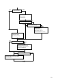
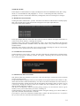
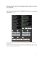
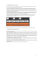
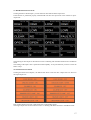
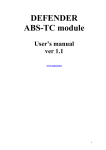
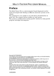
DEFENDER
alarm module
User’s manual
ver 1.1
www.nanocom.it
1
INDEX
1.1 INTRODUCTION ...................................................................................................3
1.2 GENERAL INFORMATION..................................................................................3
2 STANDALONE MODE.............................................................................................4
2.1 MENU DEF. ALLARM ..........................................................................................4
2.2 READ EVENTS FUNCTION .................................................................................4
2.3 CLEAR EVENTS FUNCTION...............................................................................5
2.4 READ SETTING FUNCTION................................................................................5
2.5 WRITE SETTING FUNCTION ..............................................................................9
2.6 INPUTS FUNCTION ............................................................................................11
2.7 OUTPUTS FUNCTIONS ......................................................................................12
2.8 PLIP LEARN FUNCTION....................................................................................12
2.9 RF TEST FUNCTION...........................................................................................12
2.10 CLEAR FACT. MODE FUNCTION ..................................................................12
2.11 SET DEFAULT FUNCTION ..............................................................................13
2.12 SET IMMOBIL. FUNCTION .............................................................................13
3 REMOTE MODE .....................................................................................................14
3.1 READ EVENTS FUNCTION ...............................................................................14
3.2 CLEAR EVENTS FUNCTION.............................................................................14
3.3 OPEN EVENT FILE FUNCTION ........................................................................14
3.4 READ SETTING FUNCTION..............................................................................15
3.5 WRITE SETTING FUNCTION ............................................................................16
3.6 OPEN SETTING FILE FUNCTION.....................................................................16
3.7 READ INPUTS FUNCTION ................................................................................17
3.8 OUTPUTS FUNCTIONS ......................................................................................17
3.9 PLIP LEARN FUNCTION....................................................................................18
3.10 RF TEST FUNCTION.........................................................................................18
3.11 CLEAR FACTORY MODE FUNCTION...........................................................18
3.12 SET DEFAULT FUNCTION ..............................................................................18
3.13 SET IMMOBIL. FUNCTION .............................................................................18
2
1.1 INTRODUCTION
In this manual only the diagnostic functions related to Defender Alarm are described and it’s taken for
garanted that the user knows the NANOCOM basic functions concerning how to explore the menus
and how to manage the NANOCOM-generated files. It’s thus recommended to carefully read the
document “NANOCOM user manual.pdf” where these subjects are dealt with.
1.2 GENERAL INFORMATION
Like the diagnostic functions related to engine TD5’s management, NANOCOM allows to perform
diagnostic functions related to DEFENDER alarm in STANDALONE mode, that is completely
independent from the PC usage by visualizing the interactive functions on the display on the
NANOCOM interface, or in REMOTE mode by employing the application NANOCOM.exe for PC.
As for the STANDALONE mode, once NANOCOM is running it is necessary to press key 3 or key 4
(<< >>) until the display shows the writing “DEF. ALARM” in order to have access to the alarm
diagnostic functions.
At this point, key 1 “ent” allows to have access to the submenu containing the various functions and
described in section 2.1.
In REMOTE mode, instead, you have to press button DEF. ALARM in the exploration area which
allows to expand the buttons that start the diagnostic functions described in chapter 3.
NOTE: Unlike the TD5 ECU and ABS’s diagnostic functions, for all the alarm diagnostic functions it’s
not necessary to have the car key inserted or the ignition turned on, as the alarm ECU is always on.
3
2 STANDALONE MODE
In this chapter it’s described how to use the diagnostic functions in STANDALONE mode, that is
without using the PC. The user is thus recommended to read paragraphs 4.1.1-4.1.2-4.1.3 describing
this mode and all paragraphs of section 4.3 explaining how to manage th files; section 4.5 dealing with
file saving; and the 4.7 concerning error messages.
2.1 MENU DEF. ALLARM
The following tree diagram shows the structure of this submenu:
DEF.ALLARM
READ EVENT
CLEAR EVENT
READ SETTING
WRITE SETTING
INPUTS
OUTPUTS
LOCK DOORS
UNLOCK DOORS
SOUNDER
ALLARM LED
IMMOBIL LAMP
HAZARD LOGHT
CURTESY LIGHT
PLIP LEARN
RF TEST
CLEAR FACT. MODE
SET DEFAULT
SET IMMOBIL.
In this menu the keys perform the following functions:
Key 1: ent
Key 2: esc
Key 3: “←←”
Key 4: “→→”
ENTER (gets the function started, or gets into the submenu in case you
choose the item “OUTPUT”)
ESCAPE (gets back to the level of the preceding menu).
scrolling the menu backward
scrolling the menu forward
2.2 READ EVENTS FUNCTION
The alarm ECU contains a register which memorizes the last 5 events triggered by the ECU itself.
Once key 1 “ent” has been pressed at the menu item READ EVENT, the writing “Read events?”
appears on the display: pressing key 1 “yes” the function gets started, whereas pressing key 4 “not” you
get back to the menu without performing the function.
If the communication is correct, the LED will flash, and if the function is completely performed, the
display will show the list of the events.
The events are listed with the numeric codes described later in this section.
At this point the keys have the following functions:
Key 1:
Key 2: esc
Key 3: “bak”
Key 4: “→→”
no function
ESCAPE (gets to the level of the previous menu).
gets to the first code
goes on to the following code
4
To get to the main menu press “esc” or scroll through all the listed events by using key 4: in both cases,
before getting to the main menu the writing “Save this file?” appears on the display. Pressing key 1
“yes” you store a file containing the 5 events triggered by the ECU; whereas pressing key 4 “not” you
get back straight to the menu.
The file generated is stored in NANOCOM’s memory with extention .fa2, it will thus be possibile to
visualize these events later in text format transferring this file on the PC.
The events are featured as follows:
EVENTn = x
where ‘n’ is the number of the event, and ‘x’ is the event’s numeric code
1 = ignition turned on
2 = driver door open
3 = any door open or tail gate( except the drivers dor )
4 = sill button
5 = tail gate opened
6 = Bonnet opened
7 = volumetric sensor opened
2.3 CLEAR EVENTS FUNCTION
Once the key 1 “ent” has been pressed at the menu item CLEAR EVENT, the writing “Clear events?”
will appear on the display: pressing key 1 “yes” the function gets started, whereas pressing key 4 “not”
you get back to the menu without performing the function.
If the communication is on, the LED will flash, and if the function is correctly performed, the display
will show the writing “event register has been cleared".
At the end of the function, you don’t need to press any key, NANOCOM gets automatically to the
menu.
2.4 READ SETTING FUNCTION
Once key 1 “ent” has been pressed at the menu item READ SETTING, the writing “Read Setting?”
will appear on the display; pressing key 1 “yes” the function starts, whereas pressing key 4 “not” you
go back to the menu without performing the function. If the communication is on, the LED will flash,
and if the function is correctly performed the display will show all the alarm settings.
Once the alarm settings have been read, the display will show them one after the other in the first line.
The keys will acquire the following functions:
Key 1:
Key 2: esc
Key 3: “←←”
Key 4: “→→”
no function
ESCAPE (gets to the level of the preceding menu).
goes to the previous code
goes to the following code
To go back to the main menu, press “esc”. Before getting to the main menu the writing “Save this
file?” appears on the display: pressing key 1 “yes” you store a file containing the read settings, whereas
pressing key 4 “not” you get back straight to the menu.
The file generated is stored in NANOCOM’s memory with extention .se2, it will thus be possibile to
visualize these settings later by transferring this file on the PC, or employ it for a WRITE SETTING
procedure.
5
The parameters allowing to perform the settings are the following:
Working settings:
Time error: allowed – none
Both the alarm and the plip have a timer allowing synchronization. A possibile difference in their
timing could prevent the codes aknowledgement. If this parameter is set on ‘allowed’, the alarm will
accepts timing errors.
Comms: normal – smart
This parameter sets the activity control of communications in standby mode.
Interior light: normal – smart
This parameter sets the interior light’s way of operation
Welcome light: disabled – enabled
This parameter allows to activate the function which turns on the interior light when the alarm is
disactivated
Arm disarm falsh: no hazard – hazard
This parameter allows to activate or disactivate the hazard light flashing when the alarm is activated or
disactivated
Arm disarm. Confirm: no hazard - hazard
This parameter allows to activate or disactivate the hazard light flashing to confirm the activation or
disactivation state, in case it is activated or disactivated many times repeatedly.
Arm on lock : disabled – enabled
This parameter allows to disable the automatic alarm activation when the car doors are locked by plip
or key.
Resync on arm : enabled – disabled
This parameter allows the synchronization between the alarm and the plip any time the alarm is
activated.
Resync on lock : enabled – disabled
This parameter allows the synchronization between the alarm and the plip any time the car is locked.
Mislock noted- ignored
This parameters indicates whether the alarm warns of a mislock, or not.
Mislock noise: disabled – enabled
This parameter indicates whether the alarm warns of a mislock through the car sounder, or not.
Plip immobilize: disabled – enabled
This parameter allows to enable or disable the immobilizer through the remote plip.
Plip relock: disabled – enabled
This parameter allows to activate or disactivate the automatic relock through the central door locking,
when the key has not been inserted for a while from the moment the alarm has been disactivate through
the remote plip.
Relock : disabled – enbled
This parameter allows to activate or disactivate the automatic lock function through the central door
locking.
Passive immobilise: disabled – enabled
This parameter allows to enable or disable the automatic immobilisation which is active a few minutes
after the key is removed and one of the doors stays open
Key disarm: disabled – enabled
This parameter allows to enable or disable the alarm’s automatic disactivation through the door
opening, also when the alarm has been previously activated through the remote plip.
Key mobilize: disabled – enabled
This parameter allows to enable or disable the immobiliser’s automatic disactivation through the door
opening, also when the alarm has been previously activated through the remote plip..
CDL when arm: none – active
This parameter allows to keep active the central door locking, also when the alarm is armed.
Flash on allarm: No flash – Hazzard
This parameter allows to enable or disable the hazard light flashing when the alarm is triggered.
Alarm sound: single – pulsed
This parameter determines of the sound is continous or pulsed.
6
Time sync: not used – used
This parameter decides whether the alarm uses or not the synchronization timers for the remote plip
aknowledgement.
Low battery: enabled – disabled
This parameter enables or disables the remote plip’s low battery, through the alarm LED.
Battery error: use count – immediate
This parameter determines whether the error warning due to the low battery is notified immediately or
afetr a certain number of errors. The error number is determined by the parameter “Plip presses for low
battery”
CAT overheat: disabled – enabled
This alarm was conceived to have two inputs able to monitor catalytic converters’ temperatures and
to warn through a proper lamp of a possible overheating.
This parameter allows to enable or disable this function. The warning threshold point is marked by the
“CAT oveheat threshold” parameter.
MEMS failure indicator: Disabled - Enabled
When the car engine is started, the engine ECU asks the alarm to send the security code. Whenever this
code doesn’t correspond to the one stored, the ECU immobilises the engine and sends a warning to the
alarm which indicates the stete of immobilisation. The parameter allows the alarm to warn the
immobilisation state through a proper lamp.
Vehicle type: DISCOVERY I – DEFENDER
This parameter determines the kind of vehicle on which the alarm is installed with the consequent
different way of operating.
Immobilizer type: GEMS – TD5MEMS – DDS – SPIDER – EDC
This alarm has the possibility to manage 5 different types of immobiliser:
GEMS indicates that the alarm is matched with an engine ECU of the GEMS type
MEMS-TD5 indicates that the alarm is matched with an engine ECU of the TD5-MEMS type
DDS indicates that the alarm is matched with an immobiliser of the DDS type ( operating on the fuel
pump )
EDC indicates that the alarm is matched with an engine ECU of the EDC type
SPIDER indicates that the alarm is matched with an immobiliser of the SPIDER type, usually installed
on vehicles which doesn’t have an engine ECU with immobiliser.
Numerical and coding settings:
Plip for easy resync:
This parameter indicates the number of times that the remote plip has to be pressed in order to allow
the easy resynchronisation.
Plip for resync:
This parameter indicates how many times you need to press the remote plip to resync it completely
with the alarm.
Bad plip code:
This parameter indicates how many times a bad rmote plip code is accepted before the alarm starts
triggering
Plip presses for low battery:
This parameter decides how many reception errors of the remote plip code are allowed before the LED
warns of the low battery.
Year of built:
The year when the alarm was built
Week of built:
The week when the alarm was built
Alarm serial number:
Serial number to identify the alarm
Number of plip learnt:
Number of remote plips stored up to that moment ( the alarm can store up to 4 different remote plips)
Volumetric sensor gain:
This parameter indicates the input gain of the volumetric sensor .
CAT overheat threshold:
This parameter indicates the threshold point below which the catalytic overheating is warned of
7
Plip code 1-1, 1-2, 1-3, 1-4 : Plip code n 1
Plip code 2-1, 2-2, 2-3, 2-4 : Plip code n 2
Plip code 3-1, 3-2, 3-3, 3-4 : Plip code n 3
Plip code 4-1, 4-2, 4-3, 4-4 : Plip code n 4
EKA code :
Manual unlock code.
GEMS code :
Security code for the GEMS type immobiliser
TD5MEMS code :
Security code for the TD5-MEMS type immobiliser
EGR-DDS code :
Security code for the DDS type immobiliser
EDC code :
Security code for the EDC type immobiliser
8
2.5 WRITE SETTING FUNCTION
This function allows to write the desired settings within the alarm memory, but you must pay particular
attention because some of these settings might cause car block, if written uncorrectly or differently
from their original values. This block is of course reversible, but it is always a good habit to read the
settings and save them in a file, in order to always keep the original settings.
At this point, it is necessary to distinguish between the working settings, which do not bear any risk if
modified but they only cause an alteration in the alarm way of working, and the numerical and coding
settings, which are used to perform the various aknowledgements and unblocks and which need thus to
be more carefully handled.
If code TD5-MEMS were modified, for example, the ECU wouldn’t start the engine because the
security code wouldn’t correspond to the one stored; or in case the EKA code is modified, everything
will run properly, but if you need to unblock the car by the key code and the related procedure, the
code doesn’t correspond to the one on the label.
The easiest way to modify settings is to perform the ‘write setting’ function without employing a file
previously stored. So, the function automatically reads the alarm settings first, allowing to modify them
and thus re-write them in a later moment. In this case, as the data to be written are directly taken from
the ECU and are manually modified, the operation can be considered safe, on condition that the user
doesn’t make mistakes with the coding data.
If you want to employ a stored file, instead, to modify the alarm settings, the ‘write setting’ function
offers two ways to operate in order to make the settings writing procedure easier and safe. The first
way writes completely all the settings stored in the file within the alarm ECU; the second one, called
‘merge’, only writes the working settings masking the coding ones. To do so, once the file has been
opened and the writing procedure is started ,NANOCOM first reads the original settings and then
merge theses data with the ones stored in the file, thus preserving the original coding data. To make
two practical examples, if you want to copy the working settings from a vehicle whose immobilizer has
been disactivated and transer them to another car, in order to disactivate the immobilizer of this second
car too, you need to perform a “read setting” function on the first car and perform a “write setting
merge” function on the second one, emplyoing the file previously generated. On the other hand, if you
need to replace the alarm ECU on a car, you need to perform a complete “write setting” in order to load
on the new ECU all the settings that have been previously stored in a file.
NANOCOM allows also in the standalone mode to modify all the alarm parameters. The procedure
allowing the settings modification is within the ‘write setting’ function. Before starting the data tranfer
the writing “edit setting?” will appear on the display. To modify the parameters you need to press key 1
yes. At this point the settings are shown one after the other and the keys perform the following
functions:
Tasto 1: esc
Tasto 2: next
Tasto 3: (-)
Tasto 4: (+)
ESCAPE (end the settings modification).
goes to the following parameter
modifies the numerical parameters decreasing them, or inverts the working
parameters
modifies the numerical parameters increasing them, or inverts the working
parameters
The modification procedure is on until you press key 1 “esc”, and a parameter can be modified more
than once, as the parameters list starts again when you press key “next” at the last parameter, so you
can edit all the settings from the beginning.
At the end of the procedure, the writing “Save this file?” appears, giving you the chance to store in a
file these newly edited parameters.
After this short explanation, you can see in details how the ‘write setting’ function operates. To explain
clearly this procedure, it’s necessary to use a flow chart which allows an easier and more intuitive
view of the different cases.
Alike the other functions, you need to press key 1 “ent” at the menu item WRITE SETTING. At this
point the chart shows what happens:
9
NO
YES
“Get from file?”
Open one of the files
that are listed
on the display
Merge current setting?
YES
NO
Save current setting?
NO
YES
Read setting…
(Nanocom reads
the settings in use
and stores them in a file)
Read setting…
(Nanocom reads
the settings in use)
NO
Edit setting?
YES
Manual modification of
parameters, wich option to
store modified data
YES
NO
Write setting now?
NANOCOM starti the procedure
of settings data
END
10
2.6 INPUTS FUNCTION
Once the key 1 “ent” has been pressed at the menu item INPUTS, the writing “Read inputs?” will
appear on the display: pressing key 1 “yes” the alarm input reading function gets started, where as
pressing key 4 “not” you get back to the menu without performing the function.
This function scans continously all the inputs with the frequency of about one second. If the
communication is on, the LED will flash continously for as long as the scan is performed.
At this point the keys perform the following functions:
Key 1:
Key 2: stop
Key 3: “←←”
Key 4: “→→”
no function
stop the scanning.
show previous parameter
show following parameter
The different parameters are shown one by one on the first line of the display.
The parameters of which the scanning is performed are the following:
Passenger sill:
Input related to the passenger’s side sill (it can be H = 12Volt or L = 0Volt)
Driver sill
Input related to driver’s side sill. (it can be H = 12Volt or L = 0Volt)
Ignition stage 2
Input related to the second ignition stage (it can be H = 12Volt or L = 0Volt)
Passenger door
Input related to the switch indicating that the passenger’s door is open (it can be H = 12Volt or L =
0Volt)
Driver door
Input related to the the switch indicating that the driver’s door is open (it can be H = 12Volt or L =
0Volt)
Door key
Input related to the switch indicating the presence of the key in the door (it can be H = 12Volt or L =
0Volt)
Bonnet
Input related to the switch indicating that the bonnet is open (it can be H = 12Volt or L = 0Volt)
MIL Light
Indicates the MIL light state
Spider circuit 1, Spider circuit 2, Spider circuit 3
Indicates the state of the spider-kind immobiliser’s three circuits ( it can be O = OPEN or C =
CLOSED )
TD5 code learnt
Indicates whether at least one valid aknowledgement between the alarm and the engine ECU TD5 has
been performed
Factory mode
Indicates if the alarm is in factory mode. This datum can be SET in case the alarm is in factory mode,
or CLEAR in case it is in working mode ( the factory mode is a particular state of the alarm when it is
just sold )
Mil status
Indicates the state of the MIL input ( this input is used by the engine ECU to inform that the
aknowledgement has not been properly performed ).
Plip1,2,3,4
These four parameters indicate the valid receptions number of the corresponding remote plip. This
count restarts when it gets to value 255
ADCSense1,2
Analog inputs of the volumetric sensor. It can acquire a value from 0 to 255 in proportion to the
voltage applied to the corresponding input.
Catalyst1,2
Analog inputs of the catalytic converters overheating; it can acquire a value from 0 to 255 in proportion
to voltage applied to the corresponding input.
11
ADCLight
Value of the output driving the courtesy light. It can acquire a value from 0 to 255 in proportion to the
corresponding output voltage.
ADCCrank
Value of the output driving the Crank output. It can acquire a value from 0 to 255 in proportion to the
corresponding output voltage.
2.7 OUTPUTS FUNCTIONS
These functions are in a submenu of the menu DEF. ALARM, so when the display shows the item
OUTPUTS, pressing key 1 “ent” you get to the submenu containing the following items. Each of these
items allows to activate the test of the corresponding output.
LOCK DOORS
UNLOCK DOORS
SOUNDER
ALARM LED
IMMOBIL LAMP
HAZARD LiGHT
COURTESY LIGHT
Locks the doors
Opens the doors
Activate the sounder
Activate the alarm LED flashing
Activate the immobilisation lamp
Activate the hazard light
Activate the courtesy light
So, you’ll perform the function by pressing key 1 “ent”.
Now the keys will acquire the following functions:
Key 1: esc
Key 2:
Key 3: “on”
Key 4: “off”
leaves the function
no function
activates the test
stops the test
Once within the function, you’ll activate the test by pressing key 3 “on”. You keep on performing it
until you press key 4 “off” or you leave the function through key 1 “esc”.
2.8 PLIP LEARN FUNCTION
This function allows the alarm to learn from one to four new remote plip codes.
Thus pressing key 1 “ent” you’ll enter the function and the writing “Plip learn active, push a key to
finish” will appear on the display.
At this point you need to repeatedly press both the remote plip buttons that you want the ECU to
aknowledge, until a pulse at the hazard lights and at the sounder warns that the learning process is over.
Now press any key to end this funcion.
2.9 RF TEST FUNCTION
This function allows the alarm to verify if the the receiving system is working properly.
In this mode any remote plip is aknowledge as valid and works normally, that is, activates and
disactivates the alarm.
Thus pressing key 1 “ent” it gets into the function and the writing “RF test active, push a key to finish”
will appear on the display.
At this point you can perform the test and at the end of it you can press any key to end the function and
get back the alarm to normal state.
2.10 CLEAR FACT. MODE FUNCTION
This function allows to clear the factory mode and thus set the alarm in normal mode.
Once key 1 “ent” has been pressed at the menu item CLEAR FACT. MODE the writing “Clr factory
mode?”, will appear on the display; pressing key 1 “yes” you’ll start the function, whereas pressing key
4 “not” you’ll get back to the menu without performing the function.
If the communication is on, the LED will flash, and if the function is ended properly, the writing
“factory mode cleared” will appear on the display.
12
2.11 SET DEFAULT FUNCTION
This function allows to set the factory mode.
Once key 1 “ent” has been pressed at the menu item SET DEFAULT the writing “Set to default?” will
appear on the display; pressing key 1 “yes” you start the function, whereas pressing key 4 “not” you get
back to the menu without performing the function.
If the communication is on, the LED will flash, and if the function is ended properly, the writing “the
ecu is set to default” will appear on the display.
NOTE: this function modifies the alarm working settings, it is thus recommended to store the original
parameters via the READ SETTING function.
2.12 SET IMMOBIL. FUNCTION
This function allows to activate the immobiliser.
Once key 1 “ent” has been pressed at the menu item SET IMMOBIL the writing “Set immobilized?”
will appear on the display; pressing key 1 “yes” you start the function, whereas pressing key 4 “not”
you get back to the menu without performing the function.
If the communication is on, the LED will flash, and if the function is ended properly, the writing “the
ecu is set to immobilized” will appear on the display.
NOTE: After immobilising the alarm with this function, to get back to normal state you need to use the
plip or the code EKA procedure.
13
3 REMOTE MODE
In this chapter it is described how to employ the diagnostic functions in REMOTE mode, that is using
the PC; it is recommended to read paragraphs 5.1.1-5.1.2-5.1.3 describing this mode, and all the
paragraphs of section 4.3 about files and memory management, and 4.6 concerning error messages.
3.1 READ EVENTS FUNCTION
Clicking the button “Read events” you start the read events function. If the function is ended properly
after a few seconds the list of the stored events will appear in the input-output data area.
The picture shows some examples:
In the input-output data area, at the end at the events list, also two buttons will appear which allow to
create a file in the PC memory, containing the read files.
The button “Save event code in a NANOCOM file (*.fa2) ” saves a file with extention .fa2 (the same
generated by NANOCOM in standalone mode). This kind of file is only visible from the application
NANOCOM.exe.
The button “Save events in a text file (*.txt)” saves a text file containing the event list. Once stored,
this text file can be opened with any text editor and thus printed.
3.2 CLEAR EVENTS FUNCTION
Clicking the button “Clear events” you start the clear events function. If the function is ended properly
after a few seconds the following window will appear, indicating that the function has been
successfully performed:
3.3 OPEN EVENT FILE FUNCTION
This function offers the possibility to open a file *.fa2, thus allowing to visualise the events contained
in a file previously saved.
Using NANOCOM in standalone mode you can read the events register and store the contents in a file,
which will be found in NANOCOM memory even after it has been switched off. In a later moment, it
will thus be possible to transfer this file to the PC through the “file manager” utility to create a copy of
it and open it through this function which will visualise the code contained in the file, or open it
directly without importing it to the PC.
This allows to do diagnostics without necessarily having a laptop, or to store the ECU state in a given
moment, even if you are distant from your house, workshop, etc.
Clicking the button “Open event file” a dialogue window will appear offering you to choose whether to
open a file contained in NANOCOM or on the PC.
If you choose to open a file contained in NANOCOM, a window will show the files in it. To open the
file you want, select one of the files and click the button “OK”.
14
If you want to open a file contained in the PC, a file browser will appear offering you to choose among
the files in the PC.
The events are visualised in the same way as in the Read events function, and here too it’s possible to
save a text-format file.
3.4 READ SETTING FUNCTION
Clicking the button “Read setting” you start the Read ECU settings function.
If the function is ended properly after a few seconds the values of these settings will appear in the
input-output area.
The picture shows an examlple:
The ECU settings are described in paragraph 2.4, which explains the READ SETTING function in
standalone mode.
The button shown below the different settings “Save setting in a NANOCOM file (*.se2)” saves a file
with extention .se2 (the same generated by NANOCOM in standalone mode). This kind of file is only
visible from the application NANOCOM.exe.
15
3.5 WRITE SETTING FUNCTION
If you want to have access to this function, you have to perform an alarm settings read first or open a
file .se2 through the OPEN SETTING FILE function.
Once you have performed one of the two operations, if you click the button WRITE SETTING you
have access to the function. The settings previously read or loaded are shown in the same way as the
read setting function, but with the difference that below all the edit boxes containing the parameters
two buttons will appear allowing to perform the parameters’ complete writing or the writing in “merge”
mode of only the working parameters.
To better understand the difference between the two ways of settings writing and understand why there
are two different ways to procede , it is recommemded to read carefully section 2.5 describing this
function in standalone mode, lingering over on the two writing methods.
Once the settings have appeared on the screen, it is possible to modify them employing mouse and
keyboard, then you can transfer them to the ECU whenever you want in one of the two modes
employing the buttons here below:
At the end of the operation a window will appear to indicate that the function has been completed.
3.6 OPEN SETTING FILE FUNCTION
This function offers the possibility to open a file *.se2, thus allowing to visualise the settings contained
in a file previously stored.
Using NANOCOM in standalone mode its possible to read the settings and store them in a file which
willbe found in the NANOCOM memory even after it has been switched off. In a later moment you can
thus transfer this file to the PC through the“file manager” utility to create a copy of it and open it
through this function, which will show the codes contained in the file, or open it directly without
importing it to the PC. This allows to do diagnostics without necessarily having a laptop or to store an
ECU settings even if you are distant from your house, workshop etc.
Clicking the button “Open setting file” a dialogue window will appear allowing to choose whether to
open a filecontained in NANOCOM or in the PC.
If you choose to open a file contained in NANOCOM, a window will show the files in it. To open the
file you want, select one of the files and click the button “OK”.
If you want to open a file contained in the PC, a file browser will appear offering you to choose among
the files in the PC.
The settings are visualised in the same way as the Read setting function.
16
3.7 READ INPUTS FUNCTION
Clicking the button “Read inputs” you start function that reads the alarm inputs state.
If the function is performed properly NANOCOM will show the input state in the interactive inputoutput area.
The meaning of these inputs is described in section 2.6 dealing with the INPUTS function in standalone
mode.
The reading of the inputs state is performed uninterruptedly. To stop the function you have to click the
button “Stop”.
3.8 OUTPUTS FUNCTIONS
Clicking the button“Test Outputs”, the buttons that allow to start the ECU outputs tests are shown in
the input-output area.
Each of these buttons activates or deactivates the corresponding output.
The single outputs tests are described in section 2.7 dealing with these functions in standalone mode.
17
3.9 PLIP LEARN FUNCTION
This functions allows the alarm to learn from one to four new remote plip codes.
Once the button “Plip learn” has been clicked, two buttons “START FUNCTION” and “STOP
FUNCTION” appear. Then click the button START FUNCTION and click repeatedly both the buttons
of the temote plils that you want the ECU to aknowledge, until a pulse at the hazard lights and at the
sounder warn of the end of the learning procedure.
Now press the key STOP FUNCTION to stop the learning session.
3.10 RF TEST FUNCTION
This function allows the alarm to test if the receiving system is working properly.
In this mode any remote plip is aknowledge as valid and works in a standard way, that is it enables or
disables the alarm.
After you click the button “RF test” two buttons “START FUNCTION” and “STOP FUNCTION”
appear. Then click the button START FUNCTION and verify that the remote plip is actually working
by activating and disactivating the alarm.
When you want to end the test, click the button STOP FUNCTION to get back to the alarm standard
functions.
3.11 CLEAR FACTORY MODE FUNCTION
This function allows to clear the factory mode and thus sets the alarm in standard mode.
Once the button “Clear factory mode” has been clicked, if the function is being performed properly,
after a few seconds the message “The factory mode is been cleared” will indicate that the function has
been correctly performed.
3.12 SET DEFAULT FUNCTION
This function allows to set the factory mode.
Once the button “Set default” has been clicked, if the function is being performed properly, after a few
seconds the message "The allarm is in the default factory mode” will indicate that the function has been
correctly performed.
NOTE: this function modifies the alarm working settings, it is thus recommended to save the original
parameters through the READ SETTING function.
3.13 SET IMMOBIL. FUNCTION
This function allows to activate the immobiliser.
Once the button “Set to immobilized” has been clicked, if the function is being performed properly,
after a few seconds the message "The allarm is set to immobilized” will indicate that the function has
been correctly performed.
NOTE: After immobilising the alarm with this function you have to use the plip or the procedure with
the EKA code to get back to normal state.
18