1
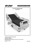
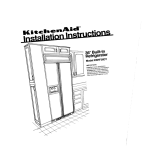
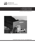
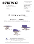
Posey Bed 8040, 8050, 8060 ® Assembly Instructions U.S. Patent No.7,047,991 & 7,383,849 Rx ONLY Table of Contents Introduction . . . . . . . . . . . . . . . . . . . . . . . . . . . . . . . . . . . . . . . . . . . . . . . . . . . . . . . . . . . . . . . . . . . . . . . . . . . . . . . . . . . . . . . 3 Specifications for the Posey Bed . . . . . . . . . . . . . . . . . . . . . . . . . . . . . . . . . . . . . . . . . . . . . . . . . . . . . . . . . . . . . . . . . . . . . . . 4 Dimensions. . . . . . . . . . . . . . . . . . . . . . . . . . . . . . . . . . . . . . . . . . . . . . . . . . . . . . . . . . . . . . . . . . . . . . . . . . . . . . . . . . . . . . . 4 General Information . . . . . . . . . . . . . . . . . . . . . . . . . . . . . . . . . . . . . . . . . . . . . . . . . . . . . . . . . . . . . . . . . . . . . . . . . . . . . . . . 5 Installation . . . . . . . . . . . . . . . . . . . . . . . . . . . . . . . . . . . . . . . . . . . . . . . . . . . . . . . . . . . . . . . . . . . . . . . . . . . . . . . . . . . . . . . . 5 Unpacking the Parts . . . . . . . . . . . . . . . . . . . . . . . . . . . . . . . . . . . . . . . . . . . . . . . . . . . . . . . . . . . . . . . . . . . . . . . . . . . . . . 6-7 Caster/Feet Installation . . . . . . . . . . . . . . . . . . . . . . . . . . . . . . . . . . . . . . . . . . . . . . . . . . . . . . . . . . . . . . . . . . . . . . . . . . . . 8-9 8050 and 8060 Models (Caster Installation). . . . . . . . . . . . . . . . . . . . . . . . . . . . . . . . . . . . . . . . . . . . . . . . . . . . . . . . . . . . 8 8040 Model (Feet Installation) . . . . . . . . . . . . . . . . . . . . . . . . . . . . . . . . . . . . . . . . . . . . . . . . . . . . . . . . . . . . . . . . . . . . . . 9 A-Frame Assembly (8040, 8050 and 8060 Models). . . . . . . . . . . . . . . . . . . . . . . . . . . . . . . . . . . . . . . . . . . . . . . . . . . . . . . . 10 Top Piece Installation. . . . . . . . . . . . . . . . . . . . . . . . . . . . . . . . . . . . . . . . . . . . . . . . . . . . . . . . . . . . . . . . . . . . . . . . . . . . . 11-12 8060 Models . . . . . . . . . . . . . . . . . . . . . . . . . . . . . . . . . . . . . . . . . . . . . . . . . . . . . . . . . . . . . . . . . . . . . . . . . . . . . . . . . 11 8040 and 8050 Models. . . . . . . . . . . . . . . . . . . . . . . . . . . . . . . . . . . . . . . . . . . . . . . . . . . . . . . . . . . . . . . . . . . . . . . . . . 12 Canopy Installation (8040, 8050, 8060 Models). . . . . . . . . . . . . . . . . . . . . . . . . . . . . . . . . . . . . . . . . . . . . . . . . . . . . . . . . . . 13 Choosing the Right Bed for Use with the Posey Bed 8040, 8050 or 8060. . . . . . . . . . . . . . . . . . . . . . . . . . . . . . . . . . . 14-15 Incompatible Beds. . . . . . . . . . . . . . . . . . . . . . . . . . . . . . . . . . . . . . . . . . . . . . . . . . . . . . . . . . . . . . . . . . . . . . . . . . . . . . . . . 15 Mattress Installation . . . . . . . . . . . . . . . . . . . . . . . . . . . . . . . . . . . . . . . . . . . . . . . . . . . . . . . . . . . . . . . . . . . . . . . . . . . . . . . 15 Attaching the Posey Bed to Hospital Beds . . . . . . . . . . . . . . . . . . . . . . . . . . . . . . . . . . . . . . . . . . . . . . . . . . . . . . . . . . . 17-22 with Non-Removable Headboards/Footboards (8040 Models) . . . . . . . . . . . . . . . . . . . . . . . . . . . . . . . . . . . . . . . . . . . . . . . . . 17 with Removable Headboards/Footboards (8050 and 8060 Models) . . . . . . . . . . . . . . . . . . . . . . . . . . . . . . . . . . . . . . . . . . . . . 18 Installing the IV Post Mount Bracket (Part Q). . . . . . . . . . . . . . . . . . . . . . . . . . . . . . . . . . . . . . . . . . . . . . . . . . . . . . . . 19-22 from the Top. . . . . . . . . . . . . . . . . . . . . . . . . . . . . . . . . . . . . . . . . . . . . . . . . . . . . . . . . . . . . . . . . . . . . . . . . . . . . . . . . . 19 from Below the IV Post. . . . . . . . . . . . . . . . . . . . . . . . . . . . . . . . . . . . . . . . . . . . . . . . . . . . . . . . . . . . . . . . . . . . . . . . . . . 20 Bed-To-Bracket Cross Reference . . . . . . . . . . . . . . . . . . . . . . . . . . . . . . . . . . . . . . . . . . . . . . . . . . . . . . . . . . . . . . . . . . . 21 IV Mounting Bracket Instructions For Stryker Beds. . . . . . . . . . . . . . . . . . . . . . . . . . . . . . . . . . . . . . . . . . . . . . . . . . . . . . . 22 Assembly Check. . . . . . . . . . . . . . . . . . . . . . . . . . . . . . . . . . . . . . . . . . . . . . . . . . . . . . . . . . . . . . . . . . . . . . . . . . . . . . . . . . . 23 Replacement Part Availability. . . . . . . . . . . . . . . . . . . . . . . . . . . . . . . . . . . . . . . . . . . . . . . . . . . . . . . . . . . . . . . . . . . . . . . . 24 Posey Limited Warranty. . . . . . . . . . . . . . . . . . . . . . . . . . . . . . . . . . . . . . . . . . . . . . . . . . . . . . . . . . . . . . . . . . . . . . . . . . . . . 25 Technical Service from Posey. . . . . . . . . . . . . . . . . . . . . . . . . . . . . . . . . . . . . . . . . . . . . . . . . . . . . . . . . . . . . . . . . . . . . . . . 26 Notes . . . . . . . . . . . . . . . . . . . . . . . . . . . . . . . . . . . . . . . . . . . . . . . . . . . . . . . . . . . . . . . . . . . . . . . . . . . . . . . . . . . . . . . . . . . 27 2 www.posey.com 1.800.447.6739 Posey Bed 8040, 8050, 8060 INTRODUCTION Introduction SAFETY INSTRUCTIONS SAFETY PRECAUTIONS The Posey Bed Assembly Instructions include important instructions and information related to the assembly of the bed. It is important to read the Assembly Instructions carefully prior to assembly of the bed for the first time. In order to ensure safe assembly, the operator must always comply with the instructions and warnings contained in the Assembly Instructions. NOTE: The protective devices installed on both the Posey Bed and the accessories may neither be removed nor modified. To help reduce the risk of serious injury or death from ENTRAPMENT, suffocation or unassisted bed exit, read and follow these instructions. SAVE THIS MANUAL FOR FUTURE REFERENCE. Read the Posey User Manual prior to use. Visit www.posey.com to download a PDF copy. Rx ONLY. Warnings, cautions, and notes are provided throughout this manual to indicate levels of potential hazards or helpful information as defined below. Indicates a safety hazard or unsafe practice, which, if not avoided, could result in serious injury or death. Indicates a potential hazard in which failure to follow instructions may result in minor or moderate injury to the patient or caregiver or damage to the Posey Bed. NOTE Indicates a reminder or other helpful information to make bed assembly easier and more efficient. NEED HELP? Posey Bed 8040, 8050, 8060 Please call Posey Customer Support at 1.800.447.6739 between 6:00 a.m. and 5:00 p.m. Pacific time if additional help is required. You can also contact an authorized Posey Bed dealer. www.posey.com 1.800.447.6739 3 INTRODUCTION Specifications for the Posey Bed OPERATING CONDITIONS The Posey Bed is designed for use in normal indoor environments. STORAGE CONDITIONS The Posey Bed may be stored in ambient warehouse temperatures at normal humidity levels. Avoid excess moisture or high humidity that may damage product materials. Dimensions Top Piece Preassembled (C1) (8060) Top Piece w/Springs (B1) (8040 and 8050) Metal Retainer (E) Slider Bar (D) Metal Retainer (E) 77”or 196 cm (8040) w/installed feet A-Frame Legs (G) Base Assembly (A) 79”or 200 cm (8050, 8060) w/installed casters Slider Bar (D) Bottom Center Piece (B2) with caster (8050/8060) with feet (8040) 76” - 96” 193 cm - 243 cm 36” 91 cm 4 www.posey.com 1.800.447.6739 Posey Bed 8040, 8050, 8060 INTRODUCTION General Information This section provides detailed installation and setup instructions for the Posey Bed 8040, 8050 and 8060. The installation steps must be followed correctly to ensure proper operation and service. Read these Assembly Instructions carefully before attempting to assemble the bed. Follow all instructions carefully. Select a place where sufficient clearance can be provided around the bed. Ample working space is necessary around and above the bed. The bed is heavy and large; therefore, it is strongly recommended that a second person assist with the assembly of the Posey Bed 8040, 8050 and 8060 to provide stability and to help prevent injury. The bed assembly portion requires two people. 8040 Long Term Care A-Frame Canopy Enclosure 8050 All Care A-Frame Canopy Enclosure 8060 All Care A-Frame Canopy Enclosure Hospital bed and mattress not included Installation PROCEDURE Posey Bed 8040, 8050, 8060 Gather assembly tools not included in the boxes. Check Quantity £ £ 1 Box cutter 2 9/16" combination wrenches or sockets www.posey.com 1.800.447.6739 Tool 5 INSTALLATION Unpacking the Parts Confirm that all parts have been included with the bed. If any items are missing or damaged, please contact Posey Technical Service at 1.800.447.6739. See page 24 for a complete list of order numbers for replacement or missing parts. A Parts Checklist used for 8040, 8050, 8060 Check Part Qty. Description £ A 2 Base assemblies (2 ea.) £ D 2 Slider bar £ E 2 Metal retainers £ F 2 A-frame padding (mint green or forest green) £ G 4 A-frame legs £ H 6 Foam tubing £ I 8 Black connecting pins £ J 4 Nuts £ K 4 Flat washers £ L 4 Silver star washers £ M 4 Allen head screws £ R 1 Canopy (vinyl: 8050; nylon: 8040, 8060) 1 Allen wrench (3/16”) £ D E F H G G I 6 www.posey.com 1.800.447.6739 Posey Bed 8040, 8050, 8060 INSTALLATION Unpacking the Parts (Continued) Parts Checklist used on 8040, 8050, 8060 (Cont.) K L J M Parts Checklist used on 8050 and 8060 Check Part Qty. Description £ B2 1 Bottom center piece with caster £ P 4 Casters £ Q 4 IV post mounting brackets B2 R P Parts Checklist used for 8040 and 8050 Check Part Qty. Description Q £ B1 1 Top center piece w/ two springs £ C 2 Top pieces w/ two corner pads Parts Checklist used for 8040 Check Part Qty. Description B1 C £ O 2 Universal bed strap £ N 4 Feet £ B2 1 Bottom center piece with preassembled foot Corner Pads Parts Checklist used on 8060 Check Part Qty. Description £ C1 1 C1 Posey Bed 8040, 8050, 8060 N O Top piece, preassembled B2 www.posey.com 1.800.447.6739 7 INSTALLATION Caster Installation (8050 and 8060 Models) MATERIALS: A • Part A (2) • Part B2 • Part J • Part K • Part L • Part M • Part P • 9/16” wrench 90 Degrees 1. Unfold each base assembly (Part A) until corners are at 90 degrees (Fig. 1). 2. Place a flat washer (Part K) over the caster post (Part P). 3. Insert the caster (Part P) into the pre-drilled hole next to the corner receptacle in the base assembly (Part A). 4. Place a star washer (Part L) and nut (Part J) on the caster bolt (Fig. 2). Use the 9/16” wrench (not provided) to tighten. 5. Repeat steps 2 through 4 on the remaining three corners. 6. Remove the Allen head screw (Part M) from the arm of each base assembly (Part A) and keep for use at a later step. 7. With slots facing inside (Fig. 3), slide the bottom center piece (Part B2) over both base assembly arms. 8. Reattach the Allen head screw in the slots of the bottom center piece (Part B2) (Fig. 4) The Allen head screws on the bottom center piece of the Posey Bed must be secure, but loose enough so the A-frame slides freely when raising or lowering the head or foot of the hospital bed. A failure to heed this warning may interfere with proper operation of the hospital bed (see red arrows Fig. 4). Fig. 1 Nut (Part J) Star Washer (Part L) A Caster (Part P) Flat Washer (Part K) Fig. 2 B2 A Base Assembly Allen Head Screw Bottom Center Piece Fig. 3 A B2 Completed Frame Assembly Fig. 4 8 www.posey.com 1.800.447.6739 Posey Bed 8040, 8050, 8060 INSTALLATION Feet Installation (8040 Model) MATERIALS: • Part A (2) • Part B2 • Part J • Part K • Part L • Part M • Part N • 9/16” Wrench A 90 Degrees 1. Unfold each base assembly (Part A) until corners are at 90 degrees (Fig. 5). 2. Place a flat washer (Part K) over the foot post (Part N) (Fig. 5). 3. Insert the feet (Part N) into the pre-drilled hole next to the corner receptacle in the base assembly (Part A). 4. Place a star washer (Part L) and nut (Part J) on the feet bolt (Fig. 6). Use the 9/16” wrench (not provided) to tighten. Feet should now be properly installed (Fig. 7). 5. Repeat steps 2 through 4 on the remaining three corners. 6. Remove the Allen head screw (Part M) from the arm of each base assembly (Part A) and keep for use at a later step. 7. With slots facing inside, slide the bottom center piece (Part B2) over both base assembly arms. 8. Reattach the Allen head screw in the slots of the bottom center piece (Part B2) (See Fig. 8). Feet (Part N) Flat Washer (Part K) Fig. 5 Nut (Part J) Star washer (Part L) Fig. 6 The Allen head screws on the bottom center piece of the Posey Bed must be secure, but loose enough so the A-frame slides freely when raising or lowering the head or foot of the hospital bed. A failure to heed this warning may interfere with proper operation of the hospital bed (see red arrows Fig. 8). Fig. 7 A B2 Completed Frame Assembly Fig. 8 Posey Bed 8040, 8050, 8060 www.posey.com 1.800.447.6739 9 INSTALLATION A-Frame Assembly (8040, 8050 and 8060 Models) MATERIALS: • Part • Part • Part • Part I D E G I I E 1. Insert the two A-Frame Legs (Part G) into the metal retainer (Part E) (Fig. 9). 2. Use the black connecting pins (Part I) to secure the two A-frame legs (Part G) with the metal retainer (Part E) (Fig. 10). 3. Insert the slider bar (Part D) into the assembled A-frame legs. 4. Repeat steps 1 through 3 for the other side. 5. Remove the Allen head screw from the vertical corner of the base assembly arm and keep for use at a later step (Fig. 11). 6. Repeat step 5 on the remaining three corners. 7. Slide the assembled A-frame legs (Part G) into each retainer with the flat face of the metal retainer (Part E) facing inside the bed. NOTE: For one-person set-up, use your foot to lift the slider bar (Part D) before placing the assembled A-frame legs into the retainers of the base assembly (Fig. 11). 8. Secure the A-frame legs to the base assembly using black connecting pins (Part I) (Figs. 12 and 13). 9. Repeat steps 7 and 8 for the other assembled A-frame legs on the opposite side. 10.Re-install the four Allen head screws from steps 5 and 6 on all four A-frames legs and tighten. G G D Fig. 9 Allen Head Screw Fig. 10 Fig. 11 D I Fig. 12 10 www.posey.com 1.800.447.6739 I A Fig. 13 Posey Bed 8040, 8050, 8060 INSTALLATION Top Piece Installation (8060 Model) MATERIALS: • Part C1 Corner Pads NOTE: Leave pre-installed corner pads in place. 1. Place the top piece (Part C1) section into the metal retainers on the head of the A-frame legs (Fig. 14). NOTE: For one-person set-up, insert the top piece one end at a time. 2. Push the silver metal detent pin into the top hole (Fig. 15). Top Hole NOTE: Make sure the silver metal detent pin protrudes out through the hole on the metal retainer. 3. Repeat step 2 for the other side of the assembled A-frame legs. NOTE: The top center piece must be able to slide freely so that the frame can move as the bed articulates. Bottom Hole Fig. 14 The bed may not always fit through some doorways. In this situation, lower the top piece to the lowest position, pushing the silver metal detent pin into the bottom hole (Fig. 14), and then return it back to the top hole after transport. Corner Pads Top Hole Bottom Hole Fig. 15 Posey Bed 8040, 8050, 8060 www.posey.com 1.800.447.6739 11 INSTALLATION Top Piece Installation (8040 and 8050 Models) MATERIALS: • Part C Corner Pads NOTE: Leave pre-installed corner pads in place. 1. Remove the two Allen head screws from the top piece (Part C) and keep for use at a later step. 2. Place each top piece section into the metal retainers on the head of the A-frame legs (Fig. 16). NOTE: For one-person set-up, insert the top piece one end at a time. 3. Push the silver metal detent pin into the top hole (Fig. 17). NOTE: Make sure the silver metal detent pin protrudes out through the hole on the metal retainer. 4. Repeat steps 1 through 3 for the other side of the assembled A-frame Legs. 5. Slide the top center piece (Part B1) with the provided springs over each top piece and then re-install. DO NOT tighten the Allen head screws from step 1. Slots should be oriented on the same side as the top piece holes. NOTE: The top center piece must be able to slide freely so that the frame can move as the bed articulates (Figs. 18 and 19). Top Hole Bottom Hole Fig. 16 Corner Pads Top Hole The bed may not always fit through some doorways. In this situation, lower the top piece to the lowest position, pushing the silver metal detent pin into the bottom hole (Fig. 16), and then return it back to the top hole after transport. The Allen head screws on the top center piece of the Posey Bed must be secure, but loose enough so the A-frame slides freely when raising or lowering the head or foot of the hospital bed. A failure to heed this warning may interfere with proper operation of the hospital bed (see red arrows Fig. 18). Bottom Hole Fig. 17 Top Piece Fully Assembled Fig. 18 B1 C Fig. 19 12 www.posey.com 1.800.447.6739 Posey Bed 8040, 8050, 8060 INSTALLATION Canopy Installation (8040, 8050, 8060 Models) MATERIALS: • Part H • Part F • Part R • Assembled H F bed frame H 1. Attach the foam padding (Part H) and the A-frame padding (Part F) to the bed frame (Figs. 20 and 21). 2. Make sure the seams of the top foam pads are oriented so the Allen head screws have space to move (Fig. 22). 3. Unfold the canopy (Part R) on the bed. ALWAYS orient the canopy so the Instruction Storage Pocket is positioned on the open side of the frame (Fig. 23). 4. Unzip the top rail zipper of the canopy (look for the large Posey logo) (Fig. 23). 5. Wrap the top of the canopy over the padded frame. 6. Fasten the support straps on each side of the top rail of the canopy before zipping (Fig. 24). 7. Insert the zipper pins properly into the zipper box and zip closed using the zipper pull-tab (Figs. 25 and 26). When zipping the canopy, make sure the zipper pins are completely seated. Failure to do this will prevent the zipper from closing securely, which may lead to unassisted bed exit and potential patient injury. To avoid damage to zippers and fabric, be sure to pull the fabric closed as each panel is fully zipped. 8. Unzip the zippers on the side pieces. 9. Wrap the canopy side piece around the padded frame legs and close the zippers (Fig. 27). 10. Repeat on all four sides. H H Fig. 20 Fig. 21 Instructions Storage Fig. 22 Fig. 23 Fig. 24 Fig. 25 Fig. 26 Fig. 27 Posey Bed 8040, 8050, 8060 www.posey.com 1.800.447.6739 13 BED ASSEMBLY Choosing the Right Bed for Use with the Posey Bed 8040, 8050 or 8060 The Posey Bed is an A-frame canopy that attaches to a compatible hospital bed. Because the canopy does not include a bed, it is very important to select the correct hospital bed for proper and safe use. Using the wrong bed may result in serious injury or death to the patient. There are a number of hospital beds in use today, from many manufacturers, that are fully compatible with the Posey Bed canopy. Hospital beds come with either removable headboards and footboards, or non-removable headboards and footboards. Compatible hospital beds must meet the following requirements: • Length of the bed frame must be ≤ 96" and does not retract < 76". • Width of bed frame must be ≤ 36". • Height of the bed platform (deck of the bed) from the floor must be able to adjust between 16 and 25 inches for the 8050 and 8060 models, and between 13 and 22 inches for the 8040 model. Depending on the features of the bed, operational limits must be also be observed when a Posey Bed canopy is in use as described in the user manual. For example, the head-of-bed angle can only be raised ≤ 70". Deck of Bed 16" - 25" Fig. 28. Deck of Bed Dimensions 8050/8060 It is important to keep the bed platform in the lowest position to keep the canopy tight and avoid material in the patient area when the patient is alone. Deck of Bed BEDS WITH REMOVABLE HEADBOARDS AND FOOTBOARDS ALWAYS use the IV post mount brackets (Part Q) on a hospital bed with removable headboard and footboard. Mounting the IV post mount bracket to the IV post socket will firmly attach the A-frame to the bed. 13" - 22" Fig. 28A. Deck of Bed Dimensions 8040 BEDS WITH NON-REMOVABLE HEADBOARDS AND FOOTBOARDS ALWAYS use the Posey Bed universal straps (Cat. 8018) for a hospital bed with a nonremovable headboard and footboard to firmly attach the frame to the bed. NEVER activate any of the features listed below while using the Posey Bed canopy: • NEVER lower the deck of the bed below sixteen inches (16") (8050 and 8060 models), or below thirteen inches (13") (8040 model) from the floor to prevent suspending the mattress above the bed deck. The bottom of the canopy must be fully supported by the bed deck to prevent canopy damage. • NEVER raise the hospital bed above twenty-five inches (25") (8050 and 8060 models), or above twenty-two inches (22") (8040 model) from the floor to the deck of the bed. • NEVER tilt the hospital bed surface head-to-foot or foot-to-head (Trendelenburg feature). • NEVER allow the hospital bed to transform into a “chair-shaped" position, where the foot of the bed can be lowered to an angle greater than five degrees (5°). Using these features will damage the canopy system and bed motors and will increase the risk of serious injury or death from ENTRAPMENT, suffocation from excess material in the patient compartment, or from an unassisted bed exit, which could result in a fall. 14 www.posey.com 1.800.447.6739 Deck of bed 16" or 17" 8050/8060 Deck of bed 13" or 14" 8040 Posey Bed 8040, 8050, 8060 BED ASSEMBLY Incompatible Beds The following bed types should NEVER be used with the Posey Bed. A failure to follow this warning may result in serious injury or death from ENTRAPMENT or suffocation, or from a fall or unassisted bed exit: • Residential-type beds. The canopy system of the Posey Bed is not designed to securely attach to residential-type beds. • Any hospital bed that cannot be lowered between sixteen (16") and seventeen inches (17") for the 8050 and 8060 model or thirteen (13") and fourteen inches (14") for the 8040 model, to keep the canopy taut and avoid a “blousing” effect and excess material in the patient compartment, which will increase the risk of entrapment or suffocation. • Any hospital bed that allows the head to be raised to an angle greater than seventy degrees (>70°). Raising the head to a greater angle will damage the canopy and increase the risk of serious injury or death from a fall of unassisted bed exit. • Any hospital bed that does not securely attach to the Posey Bed with either (1) the four IV post mount brackets or (2) the Posey Bed universal straps; as this may result in serious patient injury. NEVER allow patient weight to exceed the maximum load of 300 lbs. Mattress Installation MATERIALS: • Compatible hospital bed mattress (see mattress size below) • Assembled bed frame with canopy Choosing The Right Mattress For Use With The Posey Bed The Posey Bed 8060 mattress compartment is designed to fit either: • A standard mattress: 6" x 35" x 80" (15 cm x 89 cm x 203 cm). • An inflatable air-type mattress: 10" x 35" x 80" (25 cm x 89 cm x 203 cm). The Posey Bed 8040 and 8050 mattress compartments are designed to fit a standard mattress: 6" x 35" x 80" (15 cm x 89 cm x 203 cm). NEVER use a mattress of a different size than the compartment is designed to fit. Using a smaller mattress will result in gaps between the canopy and mattress. Using a larger mattress will stress the fabric and may damage the zipper. 1. Completely unzip the mattress compartment. NOTE (8060 only): In order to fit the ten-inch (10") (25 cm) air-type mattress, the Posey Bed 8060 mattress compartment must be fully expanded. a.Locate the expansion zipper behind the instructions storage pouch on the side panel (Fig. 29). b.Unzip the mattress compartment using the red zippers around the entire bed. Fig. 29. 8060 Mattress Compartment Location • Make sure the expansion zipper (8060 only) is closed when using a six-inch (6") (15 cm) mattress. • NEVER open or close the mattress compartment while the head or knee of the bed is in the up position, as this may damage the fabric and/or zippers. Posey Bed 8040, 8050, 8060 www.posey.com 1.800.447.6739 15 BED ASSEMBLY Mattress Installation (Continued) 2. Insert the mattress into the mattress compartment (Fig. 30). 3. Completely zip the mattress compartment. The mattress must be fully zippered into the mattress compartment at all times when a patient is in the Posey Bed. NEVER put a mattress inside the patient area. 4. Attach the canopy to the bed frame by securing both bed straps located in the middle of the long sides of the bed. The canopy bed straps must ALWAYS be connected to a movable part of the bed frame to avoid damaging the mattress compartment. 5. Insert the strap through the bed frame (Fig. 31). 6. Bring the strap up through both D-rings and then back in between the first and second D-ring (Figs. 32 and 33). 7. Pull strap straight down to tighten (Fig. 34). 8. Repeat on the other side of the bed frame. Fig. 30 Fig. 31. Bed Strap Through Frame Fig. 32. Strap Through D-Ring Fig. 33. Strap Through 2nd D-Ring Fig. 34. Bed Strap Attached 16 www.posey.com 1.800.447.6739 Posey Bed 8040, 8050, 8060 BED ASSEMBLY Attaching the Posey Bed to Hospital Beds with Non-Removable Headboards/Footboards (Included with 8040 Models) MATERIALS: • Assembled • Part D • Part O bed frame with canopy A Failure to follow these instructions may result in serious injury or death from a fall or unassisted bed exit. • ALWAYS use the Posey Bed universal straps (Cat. 8018) to firmly attach the Posey Bed frame to hospital beds with non-removable headboards and footboards. • NEVER use the universal straps on beds with removable headboards and footboards. Doing so will cause the A-frame to detach from the hospital bed when the bed is raised. • ALWAYS properly secure the Posey Bed universal straps. • ALWAYS use Posey Bed headboard/footboard pads (Cat. 8002) to cover the headboards and footboards to help prevent injury from direct contact with the solid structure. 1. Position the A-frame around the hospital bed and adjust the length of the top piece and base piece of the frame to fit around the frame of the bed. 2. Wrap the large horizontal strap A horizontally around the headboard or footboard. 3. Snap the quick-release buckle closed (Fig. 35). 4. Adjust the strap so that it fits snugly around the head or footboard (Fig. 36). NOTE: The large buckle from strap A should be facing in toward the bed. 5. Adjust the position of strap A so the three slider bar support straps are between the two vertical frame bars (Fig. 37). 6. Raise the slider bar (Part D) from the frame even with the three slider bar support straps B (Fig. 38). 7. Using the tab provided, separate the hook-and-loop from each strap and place the slider bar in the center of each strap (Fig. 39). Tighten each strap. 8. Wrap each of the small Vertical Straps C vertically around the head or footboards. 9. Snap the quick-release buckles closed (Fig. 40). 10. Adjust the straps so they are snug (Fig. 41). 11. Repeat at the other end of the bed. Fig. 35 Fig. 36 D Fig. 37 B D Fig. 38 Fig. 39 C D Fig. 40 Posey Bed 8040, 8050, 8060 www.posey.com 1.800.447.6739 Fig. 41 17 Attaching the Posey Bed to Hospital Beds with Removable Headboards/Footboards (Included with 8050 and 8060 Models) MATERIALS: • Assembled • Part D • Part M • Part Q Bed Frame with Canopy Failure to follow these instructions may result in serious injury or death from a fall or unassisted bed exit. • ALWAYS use the Posey Bed IV post mount brackets (Part Q) to firmly attach the Posey Bed frame to hospital beds with removable head and footboards. • ALWAYS properly secure the Posey Bed IV post mount brackets. Failure to attach the canopy to the bed frame properly will cause the A-frame to detach from the hospital bed. 1. Position the A-frame around the hospital bed and adjust the length of the top piece and base piece of the frame to fit around the frame of the bed. 2. Adjust the bed with the hospital bed control so the bed is approximately mid-level. 3. Turn the bed electronics OFF. 4. Remove the headboard and the footboard from the hospital bed. 5. Prepare to attach the IV post mount bracket (Part Q) to the frame of the bed. There are two ways to install the IV post mount brackets depending on the bed type and the position of the IV post: • On top of the IV post (page 19) • Below the IV post (page 20) 18 www.posey.com 1.800.447.6739 Posey Bed 8040, 8050, 8060 Installing the IV Post Mount Bracket (Part Q) from the Top 1. Position the slider bar (Part D) above the IV post opening (Figs. 42 and 43) NOTE: The location of the slider bar my be either in front of or behind the IV post depending on the location and design of the head and/or footboard. Figure 42 shows the slider bar and IV post mount bracket installed in front of the IV post. Figure 43 shows the slider bar and IV post mount bracket installed behind the IV post. 2. Attach the IV post mount bracket (Part Q) to the slider bar (Fig. 44). 3. Align the IV post mount bracket with the IV post opening (Fig. 45) and align the wedge of the bracket (Fig. 46). 4. Repeat Steps two and three on the other side of the IV post. 5. Insert the two IV post mount brackets inside the IV post (Fig. 47). 6. Tighten the top Allen head screw using the 3/16" Allen wrench (provided) (Fig. 48). The IV post mount bracket must be tightened so it does not move during bed articulation. 7. Repeat on the other side. 8. Tighten the side Allen head screw (Part M) (Fig. 49). 9. Repeat this step on the other side. 10. Repeat steps one through ten on the other end of the bed. Q D Fig. 42 Fig. 43 D Q Fig. 44 Q Fig. 45 Fig. 46 Fig. 47 Fig. 48 Posey Bed 8040, 8050, 8060 www.posey.com 1.800.447.6739 Fig. 49 19 Installing the IV Post Mount Bracket (Part Q) from Below the IV Post 1. Position the slider bar (Part D) below the IV post opening. 2. Attach the IV post mount bracket to the slider bar by aligning the IV post mount bracket with the post opening (Fig. 50). 3. Align the wedge of the bracket (Fig. 51). 4. Repeat steps 2 and 3 on the other side of the IV post. 5. Insert the two IV post mount brackets inside the IV post (Fig. 52). 6. Tighten the top Allen head screw using the 3/16" Allen wrench (provided) (Fig. 53). The IV post mount bracket must be tightened so it does not move during bed articulation. 7. Repeat on the other side. 8. Tighten the side Allen head screw (Part M). 9. Repeat this step on the other side. D Q Fig. 50 Q Fig. 51 Fig. 52 Fig. 53 20 www.posey.com 1.800.447.6739 Posey Bed 8040, 8050, 8060 BED ASSEMBLY Bed-To-Bracket Cross Reference For Hospital Bed Selection, please see pages 14-15 Bracket Type: IV post mount bracket – please see pages 21-22 for detailed instructions. D Q Hill-Rom® Century, 840 and 842 Hill-Rom® Centra 850 and 852 Hill-Rom® Advanta Bed 2000 Remove the footboard, raise the knee gatch, and attach the IV post inside the footboard, not outside. Replace the headboard and footboard to engage electronics. Q D Posey Bed 8040, 8050, 8060 www.posey.com 1.800.447.6739 21 BED ASSEMBLY IV Mounting Bracket Instructions For Stryker Beds The following instructions are for the attachment of the standard IV Post Mount Brackets for the Posey Bed (8050, 8060) to Stryker Secure II Beds. These instructions are for the foot of the bed only. To install the IV Post Bracket at the head of the bed, follow the standard method of installation. Fig. 54 Stryker® Secure II 1. Remove footboard from mounting posts (Fig. 54). 2. Place the IV Post Mount Bracket onto the slider bar with the “U” shape facing up and the post inward towards the bed (Fig. 55). 3. Insert the IV Post Mount Bracket into the bottom of the footboard mounting posts on the bed (Fig. 56, 57). 4. Tighten the IV Post Mount Bracket bolt in order to secure the bracket into the mounting post on the bed (Fig. 58). 5. Center the Slider Bar in the IV Post Mount Bracket and tighten the retaining bolt (Fig. 59). 6. Replace the footboard onto its mounting posts on the bed (Fig. 60). Be sure to inspect that the footboard and the legs of the canopy frame do not touch or come into contact while raising or lowering the bed (Figs. 61, 62). 22 Fig. 55 D Q Fig. 56 Fig. 57 Fig. 58 Fig. 59 Fig. 60 Fig. 61 Fig. 62 www.posey.com 1.800.447.6739 Posey Bed 8040, 8050, 8060 Assembly Check 1. The bed assembly is completed (Fig. 63). Check: • Bed frame feels secure with no loose or moving parts. • No foam is visible. • All zipper pins are completely seated in the pin box and all zipper teeth are engaged. • No rips or holes appear in the canopy or netting. • Zippers open easily and close securely with no holes or gaps along the entire length of the zipper. Posey Bed Instructions Storage • No hardware is left over. • Store all Posey Bed instructional material in the instruction storage pocket located on the side of the bed (Fig. 63). Fig. 63 The Posey Bed is now ready for delivery or storage. NOTE: The Posey Bed is designed for use in normal indoor environments. The Posey Bed may be stored in ambient warehouse temperatures at normal humidity levels. Avoid excess moisture or high humidity that may damage product materials. Posey Bed 8040, 8050, 8060 www.posey.com 1.800.447.6739 23 Replacement Part Availability Part No. Cat. No. Used On: (Pages 6-7) Description Qty. A Base assembly - right 1 piece RP8060BAR 8040, 8050, 8060 A Base assembly - left 1 piece RP8060BAL 8040, 8050, 8060 B1 + C Top & center pieces and two springs (complete without corner padding) 1 unit RP8040TCP 8040, 8050 B2 Center piece with caster 1 unit RP8060CPC 8050, 8060 B2 Center piece with hole 1 unit RP8040CPH 8040 C Corner pad (green) 1 pair RP8040CPG 8040, 8060 C Corner pad (light green) 1 pair RP8050CPLG 8050 C1 Top piece, preassembled 1 unit 8011 D Slider bar 1 piece RP8060SB 8040, 8050, 8060 E Metal retainer 1 piece RP8060MR 8040, 8050, 8060 F A-frame padding (green) 1 pair RP8060CP 8040, 8060 F A-frame padding (light green) 1 pair RP8050CP 8050 G A-frame leg 1 piece RP8060FL 8040, 8050, 8060 H Foam tubing 1 piece RP8060FT 8040, 8050, 8060 8060 I, J, K, L, M Hardware kit 1 kit RP8000HK 8040, 8050, 8060 J, K, L, M Hardware kit 1 kit RP8060HK 8040, 8050, 8060 N Feet 1 piece RP8040FT O Posey Bed universal strap 1 pair P Caster 1 piece RP8060CTR 8050, 8060 Q IV post mounting bracket 1 piece RP8060IV 8050, 8060 R Complete canopy - 8060, green nylon 1 piece 8060T 8060 8018 8040 8040 Please call Technical Services for more information at 1.800.44.POSEY (1.800.447.6739). 24 www.posey.com 1.800.447.6739 Posey Bed 8040, 8050, 8060 Posey Limited Warranty What Does This Warranty Cover? Posey warrants to the original purchaser that the Posey Bed 8040, 8050 and 8060 are free of defects in materials and workmanship. If the product is found to be defective in workmanship or materials, we will repair or replace it at our option at no charge, other than certain transportation and cleaning charges. How Long Does the Warranty Last? This warranty is two (2) years from the date of purchase for the canopy frame and one (1) year from the date of purchase for the canopy. Useful life of the Posey Bed canopy is estimated at three (3) years, but may be extended by proper care, maintenance, laundering, avoiding sharp objects, aggressive and destructive patients, and avoiding direct exposure to sunlight. As of March 1, 2014, Posey will no longer repair any canopy that is more than 5 years old, as determined by the year and month of manufacture. What is Not Covered by this Warranty? • Damage to the metal frame, nylon canopy, or other components caused by: 1.use in unsuitable environmental conditions or failure to assemble or maintain the product in accord with user and service instructions; 2. abuse (including but not limited to patient damage), misuse, alteration, exposure to extreme heat, or by natural or external forces (such as flood or fire). • Damage caused by alteration, modification, or repair, unless performed by Posey. • Consequential or incidental damage, including but not limited to loss of income or profits, is not covered. The laws of some countries may not allow exclusion of such damages, so this limitation may not apply to you. Cleaning and Shipping Charges: • Shipping costs for products sent to Posey must be pre-paid by you. • Posey will pay return shipping costs for repaired or replaced products via Ground Service, unless otherwise agreed. How to Get Service: Contact the Posey Technical Service hotline (1.800.447.6739) to report the problem and get a Return Merchandise Authorization (RMA). Carefully pack and ship the returned product to us, with your RMA, to Posey Company, 5635 Peck Road, Arcadia, CA 91006-0020: • In clean condition. (Canopies that are returned soiled or with an odor will be returned immediately and will not be inspected or repaired.) • With proof of purchase, and • Freight prepaid by you. Posey will inspect the product and contact you within ten (10) business days of the receipt of the item to explain the results of our inspection and what is or is not covered. How Does State Law Apply? This warranty is governed by the laws of the State of California, USA. It gives you specific legal rights. You may have other rights, which vary from state to state. This warranty does not affect any further rights that you have under the laws in your state for sale of consumer goods. Posey Bed 8040, 8050, 8060 www.posey.com 1.800.447.6739 25 Technical Service from Posey We are happy to assist you between the hours of 6 a.m. and 5 p.m. Pacific time, USA. Please call us at 1.800.44.POSEY (1.800.447.6739) or 1.626.443.3143. You can fax us at 1.800.767.3933. Shipping: Ship items to Posey Company: 5635 Peck Road, Arcadia, CA 91006-0020 USA. Canopy Repairs: To prevent damage in shipping, clean the canopy and close all zippers. In-Warranty Repairs: 1. Forward the product in clean condition with prepaid freight to the above address. 2. Clearly mark the shipping container with the RMA number. 3. Include dated proof of purchase. Out-of-Warranty Repairs: 1. Forward the product in clean condition, prepaid freight to the above address. 2. We will quote repairs on an item-by-item basis. All quotes include parts and labor. 3. If additional repairs are needed after the initial estimate, we will contact you within ten (10) business days of the receipt of the item to obtain approval of any extra charge. Repair Turn-Around: Normally, we will ship the product back to you within three weeks from the date of receipt at our warehouse. If you return multiple units, add one week per unit. We will return all units in one shipment, unless otherwise agreed. *Canopies that are returned soiled or with an odor will be returned immediately and will not be inspected or repaired. 26 www.posey.com 1.800.447.6739 Posey Bed 8040, 8050, 8060 Notes Posey Bed 8040, 8050, 8060 www.posey.com 1.800.447.6739 27 Posey Bed 8040, 8050, 8060 ® Assembly Instructions Posey Company • 5635 Peck Road, Arcadia, CA 91006-0020 USA Phone: 1.800.447.6739 • Fax: 1.800.767.3933 • www.posey.com © 2015 Posey Company. All rights reserved. M5080 REV D 020515