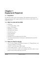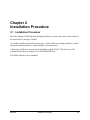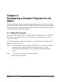
1
Order this document by
DSP56002EVMUM/D
Rev. 1.0, 3/1999
DSP56002
Evaluation Module
Quick Start Guide
Motorola, Incorporated
Semiconductor Products Sector
6501 William Cannon Drive West
Austin TX 78735-8598
© Copyright Motorola, Inc., 1999. All rights reserved.
MOTOROLA reserves the right to make changes without further notice to any products included and covered
hereby. MOTOROLA makes no warranty, representation or guarantee regarding the suitability of its products for
any particular purpose, nor does MOTOROLA assume any liability arising out of the application or use of any
product or circuit, and specifically disclaims any and all liability, including without limitation incidental,
consequential, reliance, exemplary, or any other similar such damages, by way of illustration but not limitation, such
as, loss of profits and loss of business opportunity. "Typical" parameters which may be provided in MOTOROLA
data sheets and/or specifications can and do vary in different applications and actual performance may vary over
time. All operating parameters, including "Typicals" must be validated for each customer application by customer’s
technical experts. MOTOROLA does not convey any license under its patent rights nor the rights of others.
MOTOROLA products are not designed, intended, or authorized for use as components in systems intended for
surgical implant into the body, or other applications intended to support life, or for any other application in which the
failure of the MOTOROLA product could create a situation where personal injury or death may occur. Should Buyer
purchase or use MOTOROLA products for any such unintended or unauthorized application, buyer shall indemnify
and hold MOTOROLA and its officers, employees, subsidiaries, affiliates, and distributors harmless against all
claims, costs, damages, and expenses, and reasonable attorney fees arising out of, directly or indirectly, any claim
of personal injury or death associated with such unintended or unauthorized use, even if such claim alleges that
MOTOROLA was negligent regarding the design or manufacture of the part.
Motorola and
are registered trademarks of Motorola, Inc. Motorola, Inc. is an Equal Opportunity/Affirmative
Action Employer. All other tradenames, trademarks, and registered trademarks are the property of their respective
owners.
Required Equipment
1
Installation Procedure
2
Running the Demo
3
Developing a Sample Program for the 56002
4
Using Addressing Modes
5
Filtering Audio
6
1
Required Equipment
2
Installation Procedure
3
Running the Demo
4
Developing a Sample Program for the 56002
5
Using Addressing Modes
6
Filtering Audio
Table of Contents
Chapter 1
Equipment Required
1.1
1.2
1.3
Equipment . . . . . . . . . . . . . . . . . . . . . . . . . . . . . . . . . . . . . . . . . . . . . . . . . . . . . . 1-1
What You Get with the EVM . . . . . . . . . . . . . . . . . . . . . . . . . . . . . . . . . . . . . . . 1-1
What You Need to Supply . . . . . . . . . . . . . . . . . . . . . . . . . . . . . . . . . . . . . . . . . . 1-1
Chapter 2
Installation Procedure
2.1
Installation Procedure . . . . . . . . . . . . . . . . . . . . . . . . . . . . . . . . . . . . . . . . . . . . . 2-1
Chapter 3
Running the Demo
3.1
3.2
3.3
3.4
Running the Demo . . . . . . . . . . . . . . . . . . . . . . . . . . . . . . . . . . . . . . . . . . . . . . . .
Connecting the Board for the Demo . . . . . . . . . . . . . . . . . . . . . . . . . . . . . . . . . .
Starting the Demo . . . . . . . . . . . . . . . . . . . . . . . . . . . . . . . . . . . . . . . . . . . . . . . .
Stopping the Demo. . . . . . . . . . . . . . . . . . . . . . . . . . . . . . . . . . . . . . . . . . . . . . . .
3-1
3-2
3-2
3-3
Chapter 4
Developing a Sample Program for the 56002
4.1
4.2
4.3
4.4
4.5
Writing the Program. . . . . . . . . . . . . . . . . . . . . . . . . . . . . . . . . . . . . . . . . . . . . . .
Assembling the Program . . . . . . . . . . . . . . . . . . . . . . . . . . . . . . . . . . . . . . . . . . .
Introduction to the GUI . . . . . . . . . . . . . . . . . . . . . . . . . . . . . . . . . . . . . . . . . . . .
Verifying and Debugging Programs . . . . . . . . . . . . . . . . . . . . . . . . . . . . . . . . . .
Exiting The GUI. . . . . . . . . . . . . . . . . . . . . . . . . . . . . . . . . . . . . . . . . . . . . . . . . .
4-1
4-3
4-3
4-4
4-5
Chapter 5
Using Addressing Modes
5.1
5.2
5.3
Writing the Program. . . . . . . . . . . . . . . . . . . . . . . . . . . . . . . . . . . . . . . . . . . . . . . 5-1
External Memory Configuration . . . . . . . . . . . . . . . . . . . . . . . . . . . . . . . . . . . . . 5-3
Debugging the Program . . . . . . . . . . . . . . . . . . . . . . . . . . . . . . . . . . . . . . . . . . . . 5-4
Motorola
Table of Contents
v
Chapter 6
Filtering Audio
6.1
6.2
6.3
6.4
6.4.1
vi
Application Requirements . . . . . . . . . . . . . . . . . . . . . . . . . . . . . . . . . . . . . . . . . .
Configuring the CODEC . . . . . . . . . . . . . . . . . . . . . . . . . . . . . . . . . . . . . . . . . . .
Verifying the Input and Output of Data. . . . . . . . . . . . . . . . . . . . . . . . . . . . . . . .
Implementing the Filter in the DSP . . . . . . . . . . . . . . . . . . . . . . . . . . . . . . . . . . .
Conclusion . . . . . . . . . . . . . . . . . . . . . . . . . . . . . . . . . . . . . . . . . . . . . . . . . . .
DSP56002EVM Quick Start Guide
6-1
6-1
6-1
6-4
6-8
Motorola
List of Figures
3-1
Main Features of the EVM . . . . . . . . . . . . . . . . . . . . . . . . . . . . . . . . . . . . 3-1
3-2
Alternative Configuration of J8 . . . . . . . . . . . . . . . . . . . . . . . . . . . . . . . . 3-2
3-3
Details of Pins Required to Run the Demo . . . . . . . . . . . . . . . . . . . . . . . . 3-3
4-1
The GUI . . . . . . . . . . . . . . . . . . . . . . . . . . . . . . . . . . . . . . . . . . . . . . . . . . 4-3
5-1
Unified Memory Map . . . . . . . . . . . . . . . . . . . . . . . . . . . . . . . . . . . . . . . . 5-3
5-2
Partitioned Memory Map . . . . . . . . . . . . . . . . . . . . . . . . . . . . . . . . . . . . . 5-3
6-1
Example of a Digital Filter . . . . . . . . . . . . . . . . . . . . . . . . . . . . . . . . . . . . 6-3
Motorola
List of Figures
vii
viii
DSP56002EVM Quick Start Guide
Motorola
List of Examples
4 -1
Sample Program . . . . . . . . . . . . . . . . . . . . . . . . . . . . . . . . . . . . . . . . . . . . 4-2
5 -1
Using Addressing Modes . . . . . . . . . . . . . . . . . . . . . . . . . . . . . . . . . . . . . 5-2
6 -1
Filtering Audio Program . . . . . . . . . . . . . . . . . . . . . . . . . . . . . . . . . . . . . . 6-2
6 -2
QSFILTER.ASM Code. . . . . . . . . . . . . . . . . . . . . . . . . . . . . . . . . . . . . . . 6-5
Motorola
List of Examples
ix
x
DSP56002EVM Quick Start Guide
Motorola
Chapter 1
Equipment Required
1.1 Equipment
The following section will give a brief summary of the equipment required to use the
EVM, some of which will be supplied with the EVM, and some of which will have to be
supplied by the user.
1.2 What You Get with the EVM
•
EVM board
•
3.5” disk titled ‘Debug - EVM’
•
Debug - EVM Manual
•
DSP56002 User’s Manual
•
DSP56000 Family Manual
•
DSP56002 Data Sheet
•
CS4215 Data Sheet
•
EVM Schematics
•
DSP56002 Evaluation Module Quick Start Guide
•
The main board documentation is in the form of a READ.ME file on the EVM
Software disk.
1.3 What You Need to Supply
•
A PC (386 class or higher) with 2 Mbytes of memory, a 3.5” floppy disk drive, and
a serial port capable of 19,200 baud
•
An RS-232 cable (DB-9 male to DB-9 female)
•
A power supply, between 7 V and 9 V @ 700 mA (a.c. or d.c.)
•
In order to use the demo, an audio source, headphones, and cables (with 1/8” stereo
plugs) to connect into the audio part of the board.
Motorola
Equipment Required
1-1
What You Need to Supply
1-2
DSP56002EVM Quick Start Guide
Motorola
Chapter 2
Installation Procedure
2.1 Installation Procedure
Insert the Debug - EVM disk into the floppy disk drive, ensure that you are have selected
the correct drive, and type “install”
You will be asked to specify the source drive, which will be your floppy disk drive, and to
specify the destination drive, which should be your hard drive.
A directory will then be created on the hard drive called “EVM”. This directory will
contain all the files you require to use the DSP56002EVM.
The EVM software is now installed.
Motorola
Installation Procedure
2-1
Installation Procedure
2-2
DSP56002EVM Quick Start Guide
Motorola
Chapter 3
Running the Demo
3.1 Running the Demo
The EVM software includes a demonstration program. This demonstration is designed to
show the advantage of 24-bit DSPs over 16-bit DSPs. The following section gives step by
step instructions on how to run this demo. See Figure 3-1 to see an example of an EVM.
J2
Space for EEPROM
MUSIC
SOURCE
HEADPHONES
LINE LEVEL
OUTPUT
IN
HDPHNE
32K x 8
FSRAM
J4
CS4215
32K x 8
FSRAM
OUT
32K x 8
FSRAM
J12
J17
J13
Power Supply
Inputs
7-9v a.c. or d.c.
J7
2.1mm
DSP56002
J11
Screw
Terminals
J10
J8
OnCE
HOST
To Be Connected to the
Serial Port of the PC
Figure 3-1. Main Features of the EVM
Motorola
Running the Demo
3-1
Connecting the Board for the Demo
3.2
Connecting the Board for the Demo
When you receive the board some jumpers should already have been fitted on J8, J10, and
J12. Please ensure that these jumpers have been fitted as shown in the diagram above.
Use the RS-232 cable to connect the PC’s serial port to the DB-9 connector labelled
‘OnCE’ on the EVM. This will enable the board to be controlled from the PC.
To run the demo you need a music source (with a phones output) which must be connected
to the stereo input port labelled ‘IN’ and a pair of headphones connected to the port
labelled ‘HDPHNE’.
Connect the power supply to the board using either the 2.1mm jack plug, or the screw
terminals.
When you switch on the power supply, the green LED on the board should light.
3.3 Starting the Demo
To start the demo, first start the music source and put on the headphones. Then simply
type ‘demo’ from the EVM directory. Full details of how to work the demo, and what it
demonstrates will be displayed on screen.
After the instruction page, the demo will start, and the graphical user interface (GUI) will
appear on the screen. Details on the GUI will follow in Section 4.3.
Note:
If a message appears to say that the GUI cannot communicate with the board,
try changing the position of the jumpers on J8, as shown in Figure 3-2.
J8
J8
Figure 3-2. Alternative Configuration of J8
A number of commands will then be executed. You will notice that the red LED is lit
during the execution of these commands. This indicates that the DSP is in DEBUG mode.
The demo can then be controlled using the methods described in the instruction page. For
example:
•
3-2
To hear the input signal with the added 60 Hz tone, briefly connect J17 pin 1 to
ground.
DSP56002EVM Quick Start Guide
Motorola
Stopping the Demo
•
To hear the result of the filter with the 24-bit coefficients, briefly connect J17 pin 3
to ground.
•
To hear the result of the filter with the same coefficients, but rounded to 16-bits,
briefly connect J17 pin 2 to ground.
It is suggested that you touch the relevant pin on J17 to pin 16 (bottom right hand corner)
of J7. See Figure 3-3.
J7
J17
(IRQA)
2 (IRQB)
3 (NMI)
1
16 (GND)
Figure 3-3. Details of Pins Required to Run the Demo
The reason that the contrast between the two filters is so vast is due to the fact that with
16-bit coefficients, it is impossible to place the notch of the filter exactly on 60 Hz. It is
slightly offset and will therefore miss the noise. With the 24-bit coefficients, it is possible
to place the filter on exactly 60 Hz.
3.4 Stopping the Demo
To stop the execution of the demo, type “force r” in the COMMAND window in the
bottom left corner of the screen. To exit the GUI, type “quit”.
•
An RS-232 cable (DB-9 male to DB-9 female)
•
A power supply, between 7 V and 9 V @ 700 mA (ac or dc)
•
In order to use the demo, an audio source, headphones, and cables (with 1/8” stereo
plugs) to connect into the audio part of the board.
Motorola
Running the Demo
3-3
Stopping the Demo
3-4
DSP56002EVM Quick Start Guide
Motorola
Chapter 4
Developing a Sample Program for the
56002
The following section contains a worked example detailing how to develop a very simple
program for the DSP. It will demonstrate the form of assembly programs, give instructions
on how to assemble programs, and show how the GUI can be used to verify the operation
of, and, if necessary, to debug the program.
4.1 Writing the Program
The program can be edited using one of a large number of standard editors, e.g MS-DOS
edit, Turbo C editor, EMACS, etc. It is also possible to use a word processor if it has a
‘save as text’ option.
The following program, as shown in Example 4 -1, will perform the very simple task of
adding two numbers together.
Note:
It is important to remember that the 56000 family of processors use fractional
arithmetic. Please read DSP56000 Family Manual, Section 3.3 “Data
Representation and Rounding,” if you are unfamiliar with the DSP56000
family.
Note:
A semi-colon (;) comments to the end of the line.
Labels must be left justified
Motorola
Developing a Sample Program for the 56002
4-1
Writing the Program
Example 4 -1. Sample Program
;**************************************************************************
;A SIMPLE PROGRAM
;**************************************************************************
;THIS SIMPLE PROGRAM WILL ADD TWO NUMBERS
;**************************************************************************
;Y MEMORY
;**************************************************************************
org y:$0
;instructs the assembler that we
;are referring to Y memory starting
;at location 0
input1
dc $1234
;y:input1 is defined as a $1234
;$ indicates a hexadecimal value
result
ds 1
;reserve a single word of space in
;y memory. label it ‘result’
;**************************************************************************
;X MEMORY
;**************************************************************************
org x:$0
;instruct the assembler that we are
;now referring to X data memory,
;starting at location 0
input2
dc $2345
;x:input2 is defined as $2345
;**************************************************************************
;PROGRAM
;**************************************************************************
org p:0
jmp begin
org p:$40
begin
move y:input1,y0
move x:input2,a
add y0,a
move a,y:result
jmp *
;put following program in program
;memory starting at location 0
;p:0 is the reset vector i.e where
;the DSP looks for instructions
;after a reset
;start the main program at p:$40
;above the main interrupt vectors
;load input1 into register y0
;move input2 into accumulator a
;add input1 to input 2
;store the result at location
;y:result
;this is equivalent to
;label
jmp
label
;and is therefore a never-ending,
;empty loop
;**************************************************************************
;END OF THE SIMPLE PROGRAM
;**************************************************************************
Note:
4-2
For more information on interrupt vectors refer to DSP56000 Family Manual,
Section 7.3, “Exception Processing State (Interrupt Processing).”
DSP56002EVM Quick Start Guide
Motorola
Introduction to the GUI
Once you have typed in this file, save it as add2num.asm and quit the editor.
4.2 Assembling the Program
To assemble the program you have written, type “asm56000 -a -b -l add2num.asm”.
Provided there are no errors, this will create 2 additional files:
add2num.cld
add2num.lst
The .cld file is the assembled version of the program, and this is what will be downloaded
onto the device. The .lst file is the list file which gives full details of where program and
data will be placed in the DSP memory.
If errors are reported, recheck the source (.asm) file.
4.3 Introduction to the GUI
This section will give a brief introduction to the GUI, detailing only that which is required
to work through the example. Full details of the GUI can be found in the Debug - EVM
manual.
To start up the GUI, type “evm56K”. The display you will see should be similar to
Figure 4-1.
DATA
HEX
REGISTERS
HEX
UNASSEMBLE
COMMAND
EVM>
MENU
Figure 4-1. The GUI
Motorola
Developing a Sample Program for the 56002
4-3
Verifying and Debugging Programs
The DATA window, shown in the top left corner displays the data. To display the contents
of X data memory, starting at location x:0, click in the COMMAND window and type:
“display x:0”.
The radix in which the data is shown can be changed by clicking the box which is shown
as containing the word HEX in the diagram above. Data can also be displayed in a
graphical form. To do this type “display x:0 -graph”. To change back to text type “display
x:0 -text”.
The UNASSEMBLE window shows an unassembled version of the contents of program
memory. The next instruction to be executed will be highlighted.
As already shown the COMMAND window is where OnCE commands (i.e the controlling
commands) are entered.
The REGISTERS window shows the contents of the registers of the ALU (Arithmetic
Logic Unit) and the AGU (Address Generation Unit).
4.4 Verifying and Debugging Programs
To load the add2num program developed earlier, click in the command window and type
“load add2num”.
Note:
The previous contents of the memory which are not overwritten will remain
unchanged
The instruction at P:0 will be highlighted as this will be the first instruction to be executed.
However, before we start to execute the program we should check that the values we
expect to be in data memory are there. To do this type:
display y:input1
and then
display x:input2
To step through the program, type “step” at the command prompt.
Note:
SHORTCUTS: Instead of typing in the entire command, type the start of the
command, and by pressing the space bar, the GUI will complete the remainder.
To repeat the last command, simply press return.
As you step through the code, you will see the instructions having an effect on the
registers shown in the REGISTERS window.
Once you have stepped through the program, ensure that the program has executed
correctly, by checking that y:result contains the value $3579.
4-4
DSP56002EVM Quick Start Guide
Motorola
Exiting The GUI
Stepping through the program like this is good for short programs, but is impractical for
large complex programs. The way to debug large programs is to set breakpoints. These are
user defined points at which execution of the code will stop allowing the user to step
through the section of interest.
To set a breakpoint in the add2num to check the result in accumulator a before it is moved
into Y memory, the command is “break p:$43”. You will see the breakpoint indicated in
the unassemble window.
To point the DSP back to the start point of the program, type “change pc 0”. This changes
the program counter such that it is pointing to the reset vector. To start the program
running, the command is go.
The DSP will stop when it reaches the breakpoint, you will then be able to step through
the remainder of the code.
4.5 Exiting The GUI
To exit from the GUI, type quit at the command prompt.
Motorola
Developing a Sample Program for the 56002
4-5
Exiting The GUI
4-6
DSP56002EVM Quick Start Guide
Motorola
Chapter 5
Using Addressing Modes
The following section will give details of another worked example. This one is slightly
more complicated than the previous one and will demonstrate the use of the addressing
modes, and how to configure the external memory.
5.1 Writing the Program
This file will take two lists of data, one in internal X memory, one in external Y memory,
and calculate the sum of the products of the two lists. Calculating the sum of products is
the basis for many DSP functions, therefore the DSP has a special instruction (the mac
instruction) which multiples two values and adds the result to the contents of an
accumulator. See Example 5 -1.
Note:
Motorola
You do not need to type this program, it is provided as QS_EX2.ASM
Using Addressing Modes
5-1
Writing the Program
Example 5 -1. Using Addressing Modes
;**************************************************************************
;WORKED EXAMPLE 2
;**************************************************************************
PBASE
EQU
$200
;instruct the assembler to replace
;every occurrence of PBASE with $200
XBASE
EQU
$0
;used to define the position of the
;data in X memory
YBASE
EQU
$200
;used to define the position of the
;data in Y memory
BCR
list1
list2
begin
EQU
$FFFE
;address, in X memory, of the
;bus control register
org
dc
dc
dc
x:XBASE
;internal x memory
$475638,$738301,$92673A,$898978,$091271,$F25067
$987153,$3A8761,$987237,$34B852,$734623,$233763
$F76756,$423423,$324732,$F40029
org
dc
dc
dc
y:$YBASE
;external y memory
$F98734,$800000,$FEDCBA,$487327,$957572,$369856
$247978,$8a3407,$734546,$344787,$938482,$304F82
$123456,$657784,$567123,$675634
org
jmp
p:0
begin
org
clr
move
move
movep
p:PBASE
a
#list1,r0
#list2,r4
#0,x:BCR
move
x:(r0)+,x0
;reset vector
;external program memory
;clear accumulator a
;pointer to the start of list1
;pointer to the start of list2
;want zero wait state accesses to
;the external memory
;movep (move to peripheral) allows
;you to move immediate data into a
;memory location
y:(r4)+,y0
;load value in X memory pointed to
;by the contents of r0 into x0 and
;post-increment r0
;load value in Y memory pointed to
;by r4 into y0 and post-increment
;r4
do
mac
#15,endloop
x0,y0,a
x:(r4)+,x0
y:(r0)+,y0
;parallelism allows arithmetic
;instruction, TWO data loads
;and two register post-increments
;to be done in one instruction
;cycle.
endloop
jmp
*
;*************************************************************************
5-2
DSP56002EVM Quick Start Guide
Motorola
External Memory Configuration
Note:
The jmp * instruction is NOT inside the loop.
Note:
There is a bug in this program.
5.2 External Memory Configuration
There is an option to configure the external memory of the board in two different ways.
Full details of the corresponding memory maps are in the READ.ME file.
The external memory map is controlled by the position of the jumper on J12. See
Figure 5-1 and Figure 5-2.
J12
$7FF
INTERNAL
$1FF
EXTERNAL
$FF
0
P
X
Y
Figure 5-1. Unified Memory Map
J12
$3FFF
INTERNAL
$1FF
EXTERNAL
$FF
0
P
X
Y
Figure 5-2. Partitioned Memory Map
Note:
For more details on memory maps see Section 3.2 in the DSP56002 User’s
Manual.
With the memory configured as shown in Figure 5, external memory is regarded as one
large block. There is no separation between X, Y, or P. In this configuration X:$1000,
Y:$1000, and P:$1000 are treated as the same memory cell.
Motorola
Using Addressing Modes
5-3
Debugging the Program
In the second configuration, the memory is divided into two areas. Half of the external
memory is mapped to Y, and the remainder is unified between P and X memory.
In this example we want to make use of external Y memory, and external P memory,
therefore we require the partitioned memory map. Place the jumper on J12 accordingly.
5.3 Debugging the Program
Assemble and run the program as before. i.e:
asm56000 -a -b -l QS_EX2.asm
evm56k
then
put a breakpoint in the code at the jmp * instruction
and type “go” at the COMMAND prompt.
If the program was working correctly the result in accumulator a would be :
$
FE 9F2051 6DFCC2
However there is a bug in the program, which you may have already spotted. Debug the
program!
Note:
5-4
If you can’t find the bug, see the solution at the bottom of the this page.
DSP56002EVM Quick Start Guide
Motorola
Motorola
Using Addressing Modes
5-5
SOLUTION: Registers r0 and r4 are used incorrectly inside the do loop.
r0 should be used to point to the list which is in X memory, r4 should
be used to point to the list in Y memory.
Debugging the Program
Debugging the Program
5-6
DSP56002EVM Quick Start Guide
Motorola
Chapter 6
Filtering Audio
The following section contains a more complex worked example. This will show how to
develop an application using the on-board codec, and the codec configuration file supplied
with the EVM software.
6.1 Application Requirements
The end product of this worked example will be an assembly program which will take an
audio signal, through the codec, subject it to a simple low pass filter, and output the result
back through the codec. Each step of the development will be documented.
6.2 Configuring the CODEC
The CS4215 is a sophisticated device and is therefore relatively complex to configure. An
attempt has been made to isolate the user of the EVM from this complexity by including
the files ‘ada_init.asm’ and ‘txrx_isr.asm’ with the software.
The file ‘ada_init’ can be used to initialize the codec. It has been set up such that the
parameters can be changed by the user easily by changing one of a few control words. The
code will currently be in the format necessary for the demo with the 60 Hz filter. It will
remain the same for this demonstration.
Note:
When including this file in your program, you MUST ensure that there is no
conflict in memory. e.g. The ada_init.asm program uses locations x:0..9, the
users program should therefore not use these locations.
6.3 Verifying the Input and Output of Data
The best and easiest way to verify that the codec is being configured correctly and that the
data is being received and transmitted by the DSP correctly, is to simply pass the data
straight through without any processing at all. The following program (which you will
find as QS6_3.asm) will do this. See Example 6 -1.
Motorola
Filtering Audio
6-1
Verifying the Input and Output of Data
Example 6 -1. Filtering Audio Program
;**************************************************************************
;VERIFYING THE OPERATION OF THE CODEC AND THE SSI
;THIS PROGRAM WILL CONFIGURE THE CODEC, ACCORDING TO THE PARAMETERS IN THE
;ADA_INIT.ASM FILE, AND RECEIVE AND THEN TRANSMIT AUDIO DATA WITHOUT
;AFFECTING IT.
;**************************************************************************
START
EQU $40
ORG P:0
jmp START
ORG
jsr
jsr
jsr
jsr
p:$000c
ssi_rx_isr
ssi_rx_isr
ssi_tx_isr
ssi_tx_isr
ORG
P:START
movep #$261009,x:PLL
movep #0,x:BCR
ori
#3,mr
movec
move
move
move
#0,sp
#0,omr
#$40,r6
#-1,m6
include
;SSI receive data
;SSI receive data with exception
;SSI transmit data
;SSI transmit data with exception
;These interrupt service routines
;contained in the file
;tx_rx_isr.asm.
;See 56002 manual for information
;on interrupts
;these labels are defined in the
;ada_init.asm program
;set bit0 and bit1 in the mode
;register i.e. mask interrupts
;clear hardware stack pointer
;mode 0;enabl int. PRAM;rst=0000
; initialize stack pointer
; linear addressing
; these are used by the isrs
‘ada_init.asm’
;initialize the codec
TONE_OUTPUT
TONE_INPUT
EQU
EQU
HEADPHONE_EN+LINEOUT_EN+(4*LEFT_ATTN)+(4*RIGHT_ATTN)
MIC_IN_SELECT+(15*MONITOR_ATTN)
jset
jclr
#2,x:SSISR,*
#2,x:SSISR,*
move
move
x:RX_BUFF_BASE,a ;move left sample into acc. a
x:RX_BUFF_BASE+1),b
;move right sample into acc. b
jsr
process_stereo
loop_1
6-2
;wait for frame sync. to pass
;wait for frame sync
;jump to the subroutine which will
;process the samples
DSP56002EVM Quick Start Guide
Motorola
Verifying the Input and Output of Data
move
move
move
move
move
a,x:TX_BUFF_BASE ;move a into position from which
;it can be transmitted
b,x:TX_BUFF_BASE+1
;move b into the position from
;which it can be transmitted
#TONE_OUTPUT,y0 ;set up control words
y0,x:TX_BUFF_BASE+2
#TONE_INPUT,y0
y0,x:TX_BUFF_BASE+3
jmp
loop_1
move
process_stereo
nop
nop
nop
rts
The implementation of digital filters can be found in most DSP textbooks. See Figure 6-1.
The filter described below will be implemented in the QSFILTER.ASM.
Filter order:
M=2
No. of sections
N=2
Transpose Direct Form I cascade of 2nd order sections:
H(z) =
∏
y(n)
x(n)
b10
b11
b12
b20
z-1
z-1
a11
z-1
b21
-1
a21
z
a12
b22
a22
Figure 6-1. Example of a Digital Filter
Motorola
Filtering Audio
6-3
Implementing the Filter in the DSP
For a low pass filter with a cut-off of 1 kHz, the coefficients by the filter design package
are:
b10 = 0.00371753
b11 = 0.00741518
a11 = 0.83384359
b12 = 0.00370753
a12 = -0.34867418
b20 = 0.00485158
b21 = 0.00970316
a21 = 0.86615109
b22 = 0.00485158
a22 = -0.38555753
6.4 Implementing the Filter in the DSP
The code which implements the filter is QSFILTER.ASM. The actual implementation is
such that the audio is passed straight through for about the first ten seconds, then is filtered
for ten seconds, then straight through, then filtered, and cycles like this until execution of
the program is halted. See Example 6 -2.
6-4
DSP56002EVM Quick Start Guide
Motorola
Implementing the Filter in the DSP
Example 6 -2. QSFILTER.ASM Code
;**************************************************************************
;QSFILTER : LOW PASS FILTERING DEMO FOR DSP56002EVM.
;WILL PASS AUDIO STRAIGHT THROUGH FOR APPROXIMATELY TEN SECONDS, THEN FILTER
;FOR TEN SECONDS, THEN STRAIGHT THROUGH, ETC..ETC..ETC
;**************************************************************************
START
EQU $40
coefd
ORG
dc
dc
dc
dc
dc
dc
X:$10
0.00370753
0.5
0.00741518
0.83384359
0.00370753
-0.34867418
;b10
;scaling factor
;b11
;a11
;b12
;a12
dc
dc
dc
dc
dc
dc
0.00485158
0.5
0.00970316
0.86615109
0.00485158
-0.38555753
;b20
;scaling factor
;b21
;a21
;b22
;a22
rtdelay
ORG y:$10
bsc 4,$0
ltdelay
bsc 4,$0
tempstore
ds
;define 4 locations for rtdelay,
;initialize as 0
;define 4 locations for ltdelay,
;initialize as 0
;define a single location for the
;temporary storage.
1
ORG P:0
jmp START
ORG
jsr
jsr
jsr
jsr
p:$000c
ssi_rx_isr
ssi_rx_isr
ssi_tx_isr
ssi_tx_isr
ORG
P:START
;SSI receive data
;SSI receive data with exception
;SSI transmit data
;SSI transmit data with exception
;These interrupt service routines
;contained in the file
;tx_rx_isr.asm.
;See 56002 manual for information
;on interrupts
movep #$261009,x:PLL
movep #0,x:BCR
ori
#3,mr
movec #0,sp
Motorola
;these labels are defined in the
;ada_init.asm program
;set bit0 and bit1 in the mode
;register i.e. mask interrupts
;clear hardware stack pointer
Filtering Audio
6-5
Implementing the Filter in the DSP
move
move
move
#0,omr
#$40,r6
#-1,m6
include
;mode 0;enabl int. PRAM;rst=0000
; initialize stack pointer
; linear addressing
; these are used by the isrs
‘ada_init.asm’
;initialize the codec
TONE_OUTPUT
TONE_INPUT
EQU
EQU
HEADPHONE_EN+LINEOUT_EN+(4*LEFT_ATTN)+(4*RIGHT_ATTN)
MIC_IN_SELECT+(15*MONITOR_ATTN)
do
do
jset
jclr
#$60,wait
;do for approximately 10 seconds
#$FFF,wait_inner
#2,x:SSISR,*
;wait for frame sync. to pass
#2,x:SSISR,*
;wait for frame sync
move
move
x:RX_BUFF_BASE,a ;move left sample into acc. a
x:RX_BUFF_BASE+1),b
;move right sample into acc. b
move
a,x:TX_BUFF_BASE ;move a into position from which
;it can be transmitted
b,x:TX_BUFF_BASE+1
;move b into the position from
;which it can be transmitted
#TONE_OUTPUT,y0 ;set up control words
y0,x:TX_BUFF_BASE+2
#TONE_INPUT,y0
y0,x:TX_BUFF_BASE+3
loop_1
move
move
move
move
move
wait
nop
wait_inner
do
do
jset
jclr
#$60,wait2
;do for approximately 10 seconds
#$FFF,wait2_inner
#2,x:SSISR,*
;wait for frame sync. to pass
#2,x:SSISR,*
;wait for frame sync
move
move
x:RX_BUFF_BASE,a ;move left sample into acc. a
x:RX_BUFF_BASE+1),b
;move right sample into acc. b
jsr
process_stereo
move
a,x:TX_BUFF_BASE ;move a into position from which
;it can be transmitted
b,x:TX_BUFF_BASE+1
;move b into the position from
;which it can be transmitted
#TONE_OUTPUT,y0 ;set up control words
y0,x:TX_BUFF_BASE+2
move
move
move
6-6
;jump to the subroutine which will
;process the samples
DSP56002EVM Quick Start Guide
Motorola
Implementing the Filter in the DSP
move
move
#TONE_INPUT,y0
y0,x:TX_BUFF_BASE+3
wait2
nop
wait2_inner
jmp
loop_1
move
#ltdelay,r0
jsr
move
move
move
filter
a,y:tempstorage
b,a
#rtdelay,r0
jsr
move
move
rts
filter
a,b
y:tempstorage,a
;set up pointer to left delay
;storage
;filter the left sample
;filtered value in a, store it
;move the right sample into acc. a
;set up pointer to right delay
;storage
;filter the right sample
;move filtered right sample into b
;move filtered left sample into a
move
move
ori
#LINEAR,m0
m0,m4
#$08,mr
;set up addressing mode
;set up the addressing mode
;enable the scaling mode
do
asr
#2,stage
a #<coefs,r4
move
a,x0
asr
a
process_stereo
filter
macr
mpy
mac
macr
mpy
macr
tfr
;set up pointer to the coefficients
;shift the sample right
y:(r0)+,a
;x0=ip a=delayed z-2
x:(r4)+,x1
;a= (z-2)/2
x1= bi0
x1,x0,a x:(r4)+,x1 y:(r0)-,y0
;a=(z-2)/2+(bi0*ip)=op
;x1 = 0.5 y0=delay z-1
y0,x1,a a,y1
x:(r4)+,x1
;a=(z-1)/2 x1= =a11
x0,x1,a x:(r4)+,x1
;a=(z-1)/2+(bi1*ip) x1= ai1
y1,x1,a x:(r4)+,x1
;a=(z-1)/2+(bi1*ip)+(ai1*op)
;x1 = bi2
x1,x0,a x:(r4)+,x1 a,y:(r0)+
;a=(bi1*ip) x1=ai2 save previous a
y1,x1,a
;a=(bi1*ip)+(ai2*op)
y1,a
x:(r4)+,x0 a,y:(r0)+
stage
and
rts
Motorola
#$F3,mr
Filtering Audio
6-7
Implementing the Filter in the DSP
include ‘txrx_isr.asm’
end
6.4.1 Conclusion
You have now come to the end of the quick start document, and hopefully it has given you
a good basic understanding of the EVM. For further information please refer to the
manuals provided.
6-8
DSP56002EVM Quick Start Guide
Motorola
1
Required Equipment
2
Installation Procedure
3
Running the Demo
4
Developing a Sample Program for the 56002
5
Using Addressing Modes
6
Filtering Audio
Required Equipment
1
Installation Procedure
2
Running the Demo
3
Developing a Sample Program for the 56002
4
Using Addressing Modes
5
Filtering Audio
6